chapter 31) faraday’s law 31.1) faraday’s law of induction this chapter deals with electric...
TRANSCRIPT
CHAPTER 31) FARADAY’S Law
31.1) FARADAY’S LAW OF INDUCTION
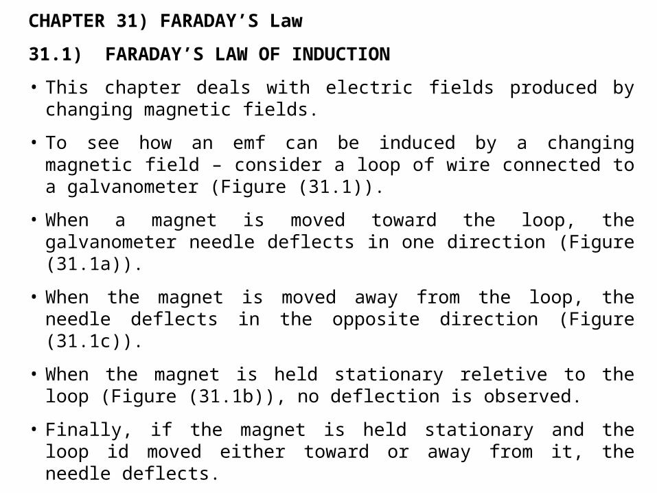
• This chapter deals with electric fields produced by changing magnetic fields.
• To see how an emf can be induced by a changing magnetic field – consider a loop of wire connected to a galvanometer (Figure (31.1)).
• When a magnet is moved toward the loop, the galvanometer needle deflects in one direction (Figure (31.1a)).
• When the magnet is moved away from the loop, the needle deflects in the opposite direction (Figure (31.1c)).
• When the magnet is held stationary reletive to the loop (Figure (31.1b)), no deflection is observed.
• Finally, if the magnet is held stationary and the loop id moved either toward or away from it, the needle deflects.
• Conclusions : i) the loop ‘know’ that the magnet is moving reletive to it because it experiences a change in magnetic field, ii) a relationship exists between current and changing megnetic field, iii) a current is set up eventhough no batteries are present in the circuit, iv) such a current is induced current and it is produced by an induced emf.
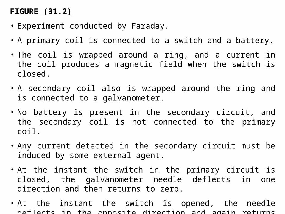
FIGURE (31.2)
• Experiment conducted by Faraday.
• A primary coil is connected to a switch and a battery.
• The coil is wrapped around a ring, and a current in the coil produces a magnetic field when the switch is closed.
• A secondary coil also is wrapped around the ring and is connected to a galvanometer.
• No battery is present in the secondary circuit, and the secondary coil is not connected to the primary coil.
• Any current detected in the secondary circuit must be induced by some external agent.
• At the instant the switch in the primary circuit is closed, the galvanometer needle deflects in one direction and then returns to zero.
• At the instant the switch is opened, the needle deflects in the opposite direction and again returns to zero.
• Finally, the galvanometer reads zero when there is either a steady current of no current in the primary circuit.
To understand what happens
The switch is closed
the current in the primary circuit produces a magnetic field
in the region of the circuit
The magnetic field produced by the current in the primary circuit changes from zero to some value over some finited time
It is this changing field that induces a current in the secondary circuit

• From these observations, Faraday concluded that : An electric current can be induced in a circuit (the secondary circuit in our setup) by a changing magnetic field.
• The induced current exists for only a short time while the magnetic field through the secondary coil is changing.
• Once the magnetic field reaches a steady value, the current in the secondary coil disappears.
• In effect, the secondary circuit behaves as though a source of emf were connected to it for a short time.
• It is customary to say that : An induced emf is produced in the secondary circuit by the changing magnetic field.
• The experiment in Figure (31.1) and (31.2) have one thing in common : In each case, an emf is induced in the circuit when the magnetic flux through the circuit changes with time.
• In general, the emf induced in a circuit is directly proportional to the time rate of change of the magnetic flux through the circuit.
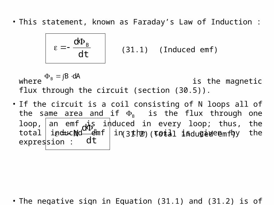
• This statement, known as Faraday’s Law of Induction :
where is the magnetic flux through the circuit (section (30.5)).
• If the circuit is a coil consisting of N loops all of the same area and if B is the flux through one loop, an emf is induced in every loop; thus, the total induced emf in the coil is given by the expression :
• The negative sign in Equation (31.1) and (31.2) is of important physical significance (Section (31.3)).
dt
d B (31.1) (Induced emf)
AdBB
dt
dN B
(31.2) (Total induced emf)
A
B
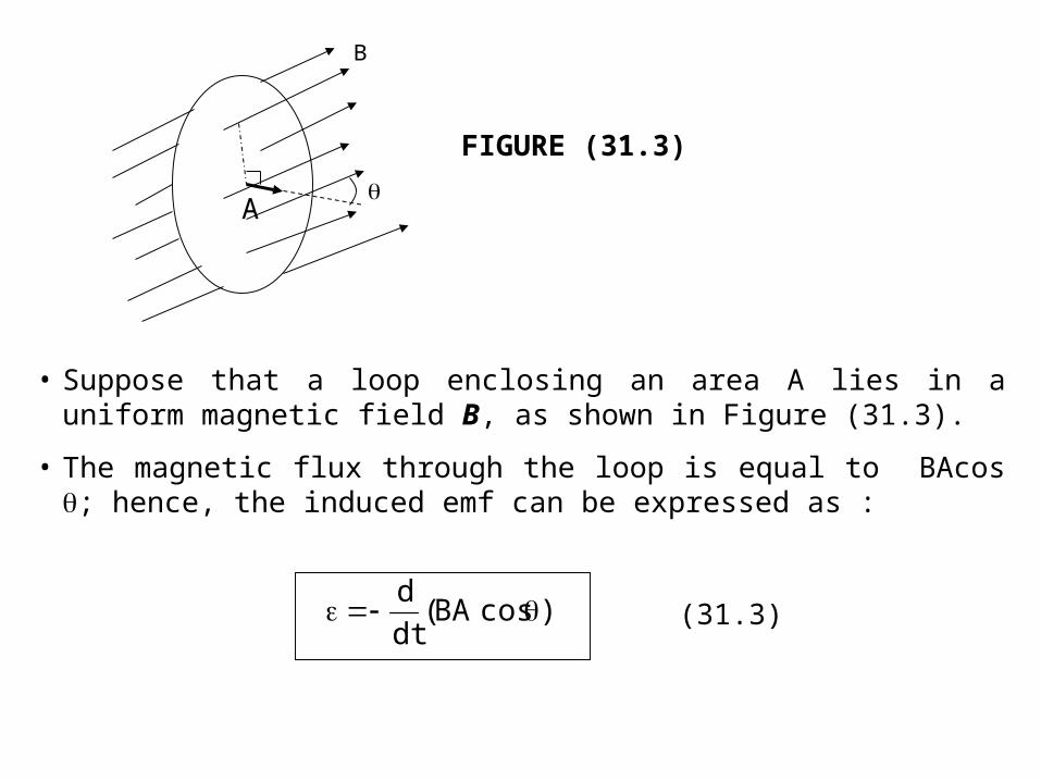
FIGURE (31.3)
• Suppose that a loop enclosing an area A lies in a uniform magnetic field B, as shown in Figure (31.3).
• The magnetic flux through the loop is equal to BAcos ; hence, the induced emf can be expressed as :
)cosBA(dt
d (31.3)

Example (31.1) : One way to Induce an emf in a coil
A coil consists of 200 turns of wire having a total resistance of 2.0 . Each turn is a square of side 18 cm, and a uniform magnetic field directed perpendicular to the plane of the coil is turned on. If the field changes linearly form 0 to 0.50 T in 0.80s, what is the magnitude of the induced emf in the coil while the field is changing.
Solution
• The area of one turn of the coil is (0.18m)2 = 0.0324 m2.
• The magnetic flux through the coil at t=0 is zero because B=0 at that time.
• At t=0.80s, the magnetic flux through one turn is : B = BA = (0.50T)(0.0324m2) = 0.0162T.m2
• Therefore, the magnitude of the induced emf is, from Eq. (31.2) :
V1.4s/m.T1.4s80.0
)m.T0m.T0162.0(200
t
N 222
B
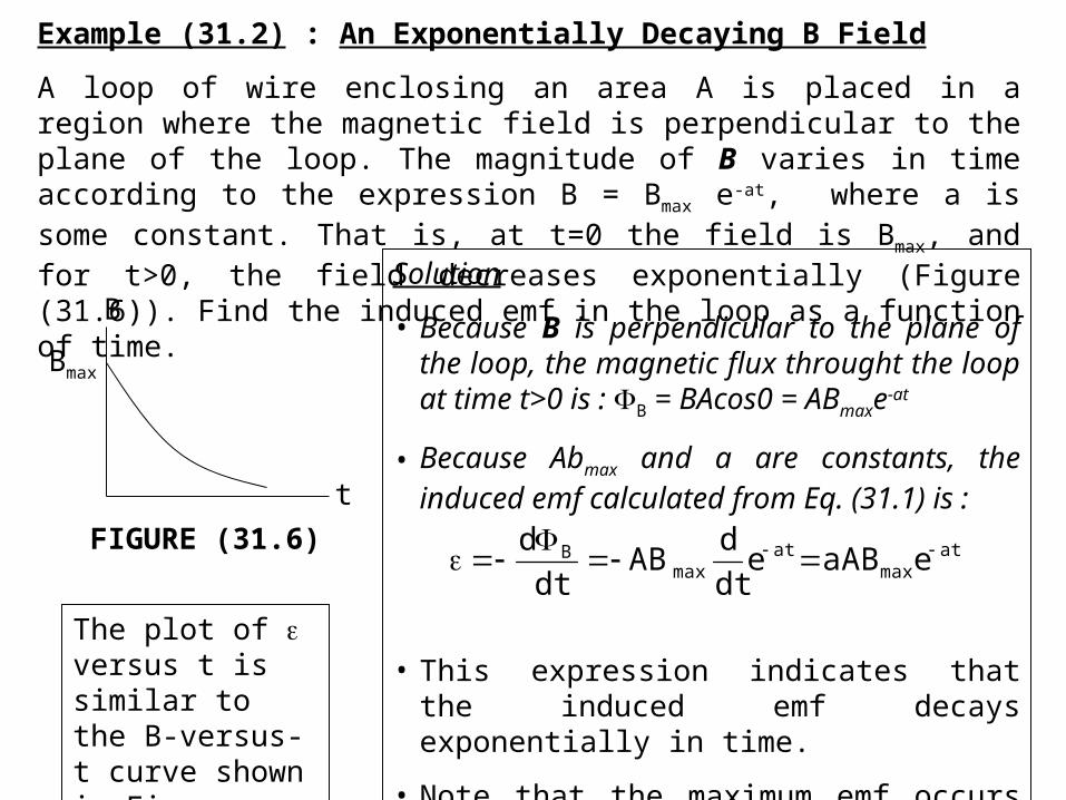
Example (31.2) : An Exponentially Decaying B Field
A loop of wire enclosing an area A is placed in a region where the magnetic field is perpendicular to the plane of the loop. The magnitude of B varies in time according to the expression B = Bmax e-at, where a is some constant. That is, at t=0 the field is Bmax, and for t>0, the field decreases exponentially (Figure (31.6)). Find the induced emf in the loop as a function of time.
B
Bmax
t
FIGURE (31.6)
Solution
• Because B is perpendicular to the plane of the loop, the magnetic flux throught the loop at time t>0 is : B = BAcos0 = ABmaxe-at
• Because Abmax and a are constants, the induced emf calculated from Eq. (31.1) is :
• This expression indicates that the induced emf decays exponentially in time.
• Note that the maximum emf occurs at t=0, where max = aABmax.
atmax
atmax
B eaABedt
dAB
dt
d
The plot of versus t is similar to the B-versus-t curve shown in Fig. (31.6)
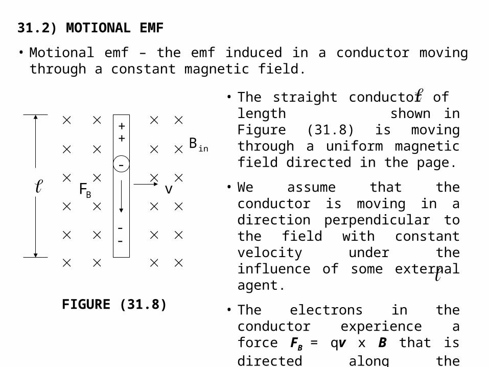
31.2) MOTIONAL EMF
• Motional emf – the emf induced in a conductor moving through a constant magnetic field.
-
--
++
BF
v
inB
FIGURE (31.8)
• The straight conductor of length shown in Figure (31.8) is moving through a uniform magnetic field directed in the page.
• We assume that the conductor is moving in a direction perpendicular to the field with constant velocity under the influence of some external agent.
• The electrons in the conductor experience a force FB = qv x B that is directed along the length , perpendicular to both v and B (Equation (29.1)).
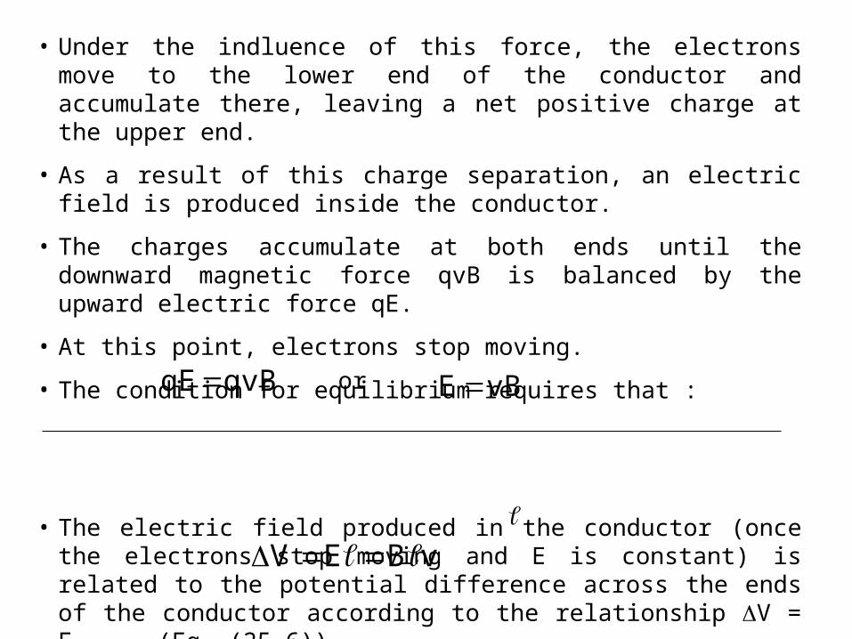
• Under the indluence of this force, the electrons move to the lower end of the conductor and accumulate there, leaving a net positive charge at the upper end.
• As a result of this charge separation, an electric field is produced inside the conductor.
• The charges accumulate at both ends until the downward magnetic force qvB is balanced by the upward electric force qE.
• At this point, electrons stop moving.
• The condition for equilibrium requires that :
• The electric field produced in the conductor (once the electrons stop moving and E is constant) is related to the potential difference across the ends of the conductor according to the relationship V = E (Eq. (25.6)).
• Thus, (31.4)
Where the upper end is at a higher electric potential than the lower end.
qvBqE or vBE
vBEV
• Thus, a potential difference is maintained between the ends of the conductor as long as the conductor continues to move through the uniform magnetic field.
• If the direction of the motion is reversed, the polarity of the potential difference also is reversed.
When the moving conductor is part of a closed conducting path :
• This situation – to illustrate how a changing magnetic flux xauses an induced current in a closed circuit.
• Consider a circuit consisting of a conducting bar of length sliding along two fixed parallel conductiong rails (Figure (31.9a)).
• We assume that the bar has zero resistance and that the stationary part of the circuit has a resistance R.
• A uniform and constant magnetic field B is applied perpendicular to the plane of the circuit.
• As the bar is pulled to the right with a velocity v, under the influence of an applied force Fapp, free charges in the bar experience a magnetic force directed along the length of the bar.
• This force sets up an induced current because the charges are free to move in the closed conducting path.
• In this case, the rate of charge of magnetic flux through the loop and the corresponding induced motional emf across the moving bar are proportional to the change in area of the loop.
• If the bar is pulled to the right with a constant velocity, the work done bye the applied force appears as internal energy in the resistor R (Section (27.6)).
• Because the area enclosed by the circuit at any instant is , where x is the width of the circuit at any instant, the magnetic flux through that area is :
• Using Faraday’s Law, and noting that x changes with time at a rate dx/dt = v, we find that the induced motional emf is :
x
xBB
dt
dxB)xB(
dt
d
dt
d B
vB (31.5)
• Because the resistance of the circuit is R, the magnitude of the induced current is :
• Figure (31.9b) – the equivalent circuit diagram for this example.
• Let us examine the system using energy considerations.
• Because no battery is in the circuit, we might wonder about the origin of the induced current and the electrical energy in the system.
• Unserstand the source of this current and energy – by noting that the applied force does work on the conducting bar, thereby moving charges through a magnetic field.
• Their movement through the field causes the charges to move along the bar with some average drift velocity, and hence a current is established.
R
vB
RI
(31.6)
• Because energy must be conserved, the work done by the applied force on the bar during some time interval must equal the electrical energy supplied by the induced emf during the same interval.
• If the bar moves with constant speed, the work done on it must equal the energy delivered to the resistor during this time interval.
• As it moves through the uniform magnetic field B, the bar experiences a magnetic force FB of magnitude I B (Section (29.2)).
• The direction of this force is opposite the motion of the bar, to the left in Figure (31.9a).
• Because the bar moves with constant velocity, the applied force must be equal in magnitude and opposite in direction to the magnetic force, or to the right in Figure (31.9a).
• If FB acted in the direction of motion, it would cause the bar to accelerate.
• Such a situation would violate the principle of conservation of energy.

• Using Equation (31.6) and the fact that Fapp=I B, we find that the power delivered by the applied force is :
• Example (31.4) : Motional emf Induced in a Rotating Bar
A conducting bar of length rotates with a constant angular speed about a pivot at one end. A uniform magnetic field B is directed perpendicular to the plane of rotation, as shown in Figure (31.10). Find the motional emf induced between the ends of the bar.
RR
vBv)BI(vF
2222
app
(31.7)
inB
dr
r
v
O
FIGURE (31.10)
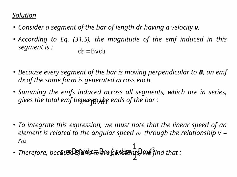
Solution
• Consider a segment of the bar of length dr having a velocity v.
• According to Eq. (31.5), the magnitude of the emf induced in this segment is :
• Because every segment of the bar is moving perpendicular to B, an emf d of the same form is generated across each.
• Summing the emfs induced across all segments, which are in series, gives the total emf between the ends of the bar :
• To integrate this expression, we must note that the linear speed of an element is related to the angular speed through the relationship v = r.
• Therefore, because B and are constants, we find that :
Bvdrd
Bvdr
20 B
2
1rdrBvdrB
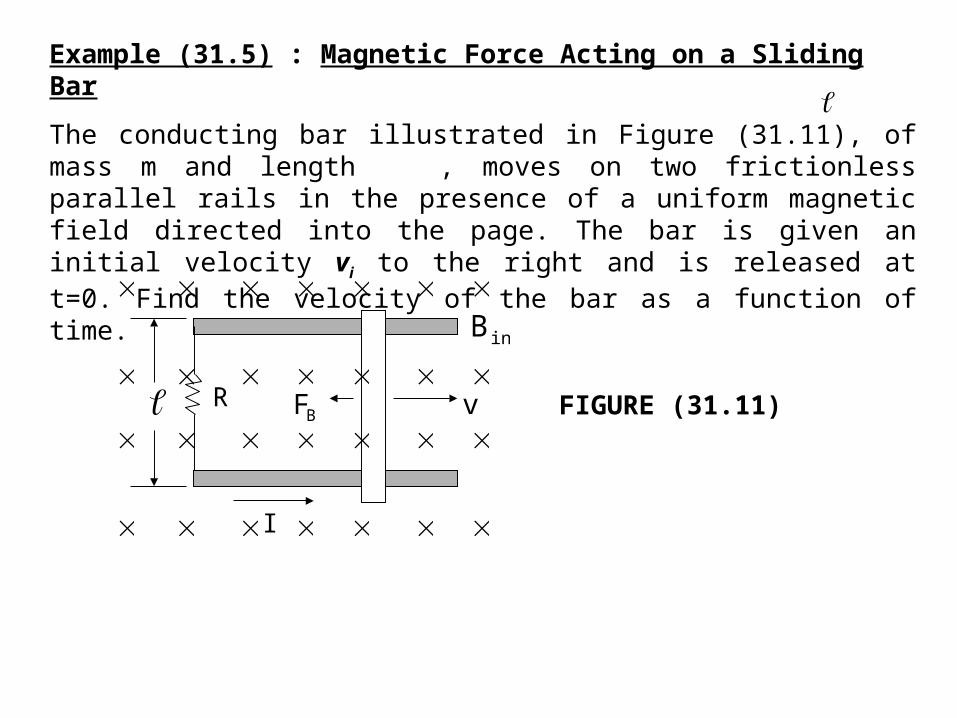
Example (31.5) : Magnetic Force Acting on a Sliding Bar
The conducting bar illustrated in Figure (31.11), of mass m and length , moves on two frictionless parallel rails in the presence of a uniform magnetic field directed into the page. The bar is given an initial velocity vi to the right and is released at t=0. Find the velocity of the bar as a function of time.
inB
R
I
BF
v
FIGURE (31.11)

Solution
• The induced current is counterclockwise, and the magnetic force is FB = -I B, where the negative sign denotes that the force is to the left and retards the motion.
• This is the only horizontal force acting on the bar, and hence Newton’s second law applied to motion in the horizontal direction gives :
• From Eq. (31.6), we know that I=B v/R, and so we can write this expression as :
BIdt
dvmmaFx
vR
B
dt
dvm
22
dtmR
B
v
dv 22
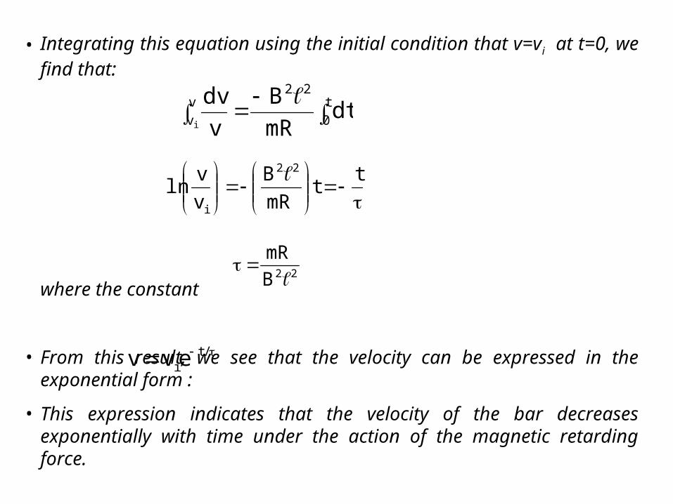
• Integrating this equation using the initial condition that v=vi at t=0, we find that:
where the constant
• From this result, we see that the velocity can be expressed in the exponential form :
• This expression indicates that the velocity of the bar decreases exponentially with time under the action of the magnetic retarding force.
t0
22vv dt
mR
B
v
dvi
tt
mR
B
v
vln
22
i
22B
mR
/tievv
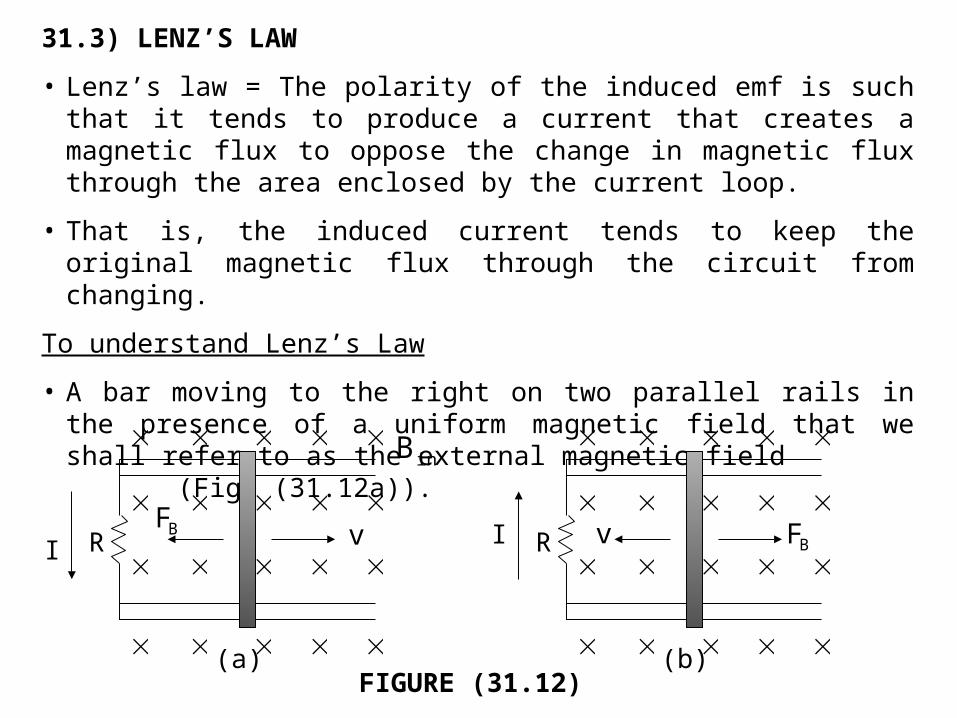
31.3) LENZ’S LAW
• Lenz’s law = The polarity of the induced emf is such that it tends to produce a current that creates a magnetic flux to oppose the change in magnetic flux through the area enclosed by the current loop.
• That is, the induced current tends to keep the original magnetic flux through the circuit from changing.
To understand Lenz’s Law
• A bar moving to the right on two parallel rails in the presence of a uniform magnetic field that we shall refer to as the external magnetic field (Fig. (31.12a)).
(a) (b)
inB
I RBF
v
I R v
BF
FIGURE (31.12)
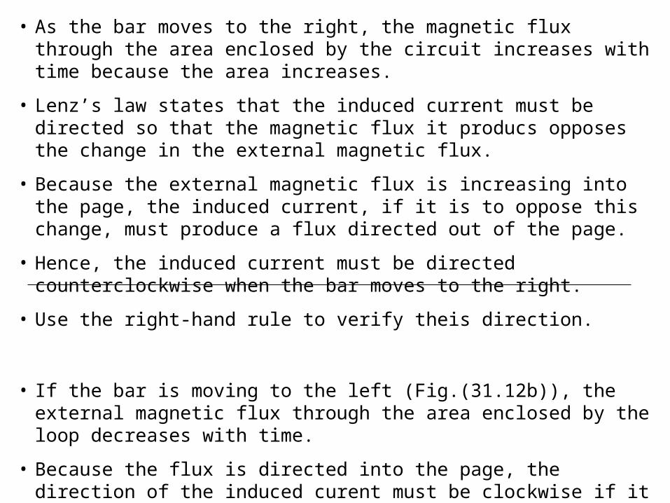
• As the bar moves to the right, the magnetic flux through the area enclosed by the circuit increases with time because the area increases.
• Lenz’s law states that the induced current must be directed so that the magnetic flux it producs opposes the change in the external magnetic flux.
• Because the external magnetic flux is increasing into the page, the induced current, if it is to oppose this change, must produce a flux directed out of the page.
• Hence, the induced current must be directed counterclockwise when the bar moves to the right.
• Use the right-hand rule to verify theis direction.
• If the bar is moving to the left (Fig.(31.12b)), the external magnetic flux through the area enclosed by the loop decreases with time.
• Because the flux is directed into the page, the direction of the induced curent must be clockwise if it is to produce a flux that also is directed into the page.
• In either case, the induced current tends to maintain the original flux through the area enclosed by the current loop.
From the viewpoint of energy considerations
• Suppose that the bar is given a slight push to the right.
• In the preceding analysis, this motion sets up a counterclockwise current in the loop.
• If we assume that the current is clockwise, such that the direction of the magnetic force exerted on the bar is to the right – this force would accelerate the rod and increase its velocity.
• This would cause the area enclosed by the loop to increase more rapidly; this would result in an increase in the induced current, which would cause an increase in the force, which would produce an increase in the current, and so on.
• In effect, the system would acquire energy with no additional input of energy.
• This clearly inconsistent with all experience and with the law of conservation of energy.
• Thus, we are forced to conclude that the current must be counterclockwise.
Situation where a bar magnet moves towards a stationary metal loop
• Figure (31.13a) – as the magnet moves to the right toward the loop, the external magnetic flux through the loop increases with time.
• Figure (31.13b) - To counteract this increase in flux to the right, the induced current produces a flux to the left, as illustrated in
Fig. (31.13b); hence, the induced current is in the direction shown.
• Note that the magnetic field lines associated with the induced current oppose the motion of the magnet.
• Knowing that like magnetic poles repel each other, we conclude that the left face of the current loop is in essence a north pole and that the right face is a south pole.
• Figure (31.13c) – If the magnet moves to the left, its flux through the area enclosed by the loop, which is directed to the right, decreases in time.
• Figure (31.13d) – Show the direction of the induced current in the loop, because this current direction produces a magnetic flux in the same direction as the external flux.
• In this case, the left face of the loop is a south pole and the right face is a north pole.
EXAMPLE (31.6) : Application of Lenz’s Law
A metal ring is placed near a solenoid, as shown in Fig. (31.15a). Find the direction of the induced current in the ring (a) at the instant the switch in the circuit containing the solenoid is thrown closed, (b) after the switch has been closed for several seconds, and (c) at the instant the switch is thrown open.

Solution for (a)
• At the instant the switch is thrown closed, the situation changes from one in which no magnetic flux passes through the ring to one in which flux passes through in the direction shown in Figure (31.15b).
• To counteract this change in the flux, the current induced in the ring must set up magnetic field directed from left to right in Figure (31.15b).
• This requires a current directed as shown.
Solution for (b)
• After the switch has been closed for several seconds, no change in the magnetic flux through the loop occurs; hence, the induced current in the ring is zero.
Solution for (c)
• Opening the switch changes the situation from one in which magnetic flux passes through the ring to one in which there is no mangetic flux.
• The direction of the induced current is as shown in Figure (31.15c) because current in this direction produces a magnetic field that is directed right to left and so counteracts the decrease in the field produced bye the solenoid.
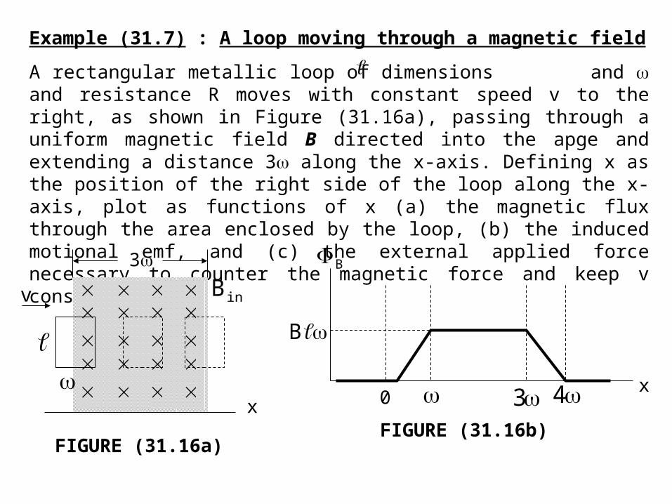
Example (31.7) : A loop moving through a magnetic field
A rectangular metallic loop of dimensions and and resistance R moves with constant speed v to the right, as shown in Figure (31.16a), passing through a uniform magnetic field B directed into the apge and extending a distance 3 along the x-axis. Defining x as the position of the right side of the loop along the x-axis, plot as functions of x (a) the magnetic flux through the area enclosed by the loop, (b) the induced motional emf, and (c) the external applied force necessary to counter the magnetic force and keep v constant.
3
v
x
inB
FIGURE (31.16a)
B
B
0 3x4
FIGURE (31.16b)
x
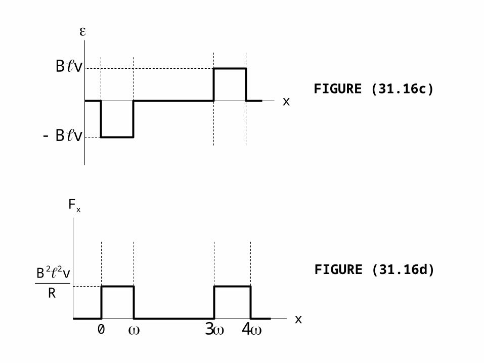
vB
vB
FIGURE (31.16c)
x 3 40
Fx
R
vB 22 FIGURE (31.16d)
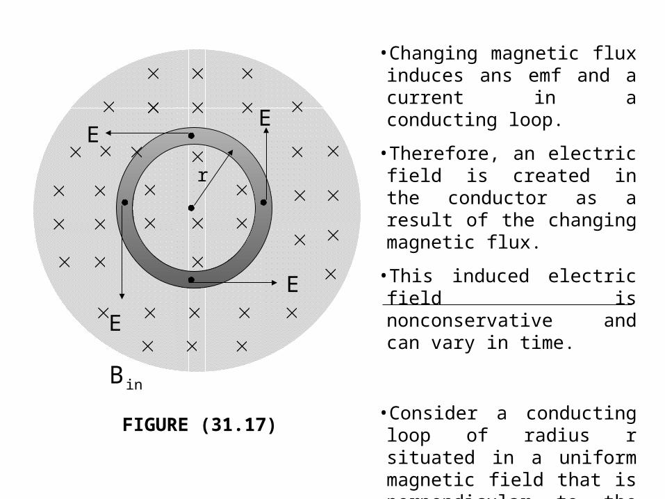
FIGURE (31.17)
r
E
E
E
E
inB
•Changing magnetic flux induces ans emf and a current in a conducting loop.
•Therefore, an electric field is created in the conductor as a result of the changing magnetic flux.
•This induced electric field is nonconservative and can vary in time.
•Consider a conducting loop of radius r situated in a uniform magnetic field that is perpendicular to the plane of the loop (Figure (31.17)).
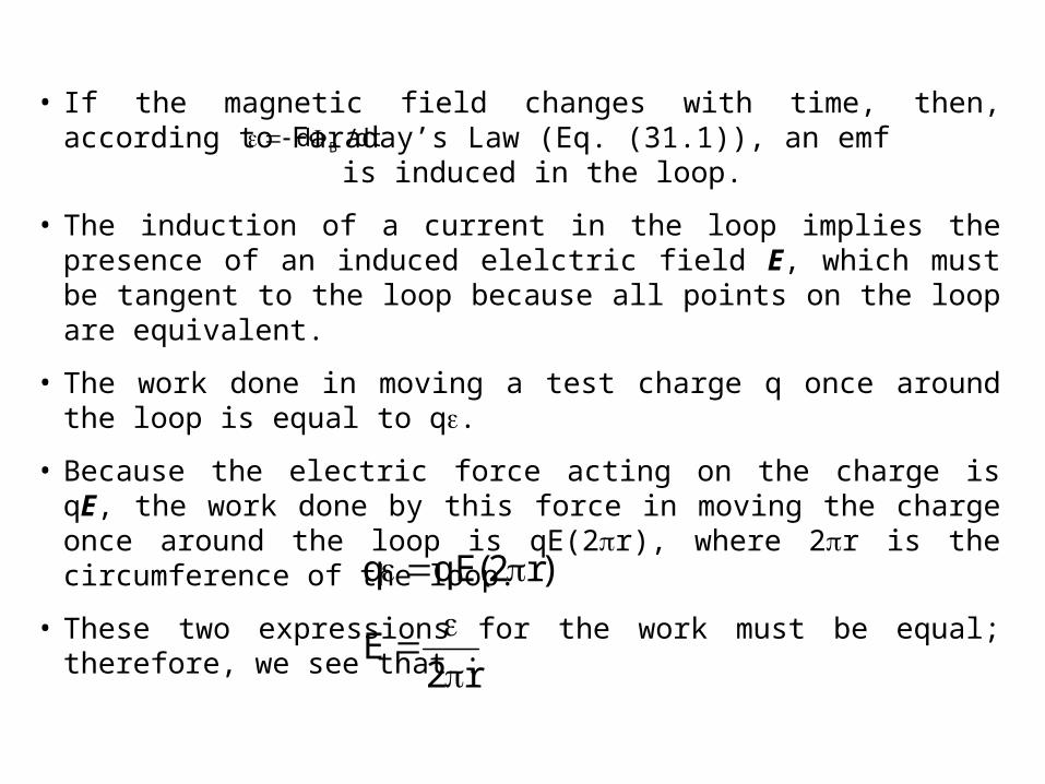
• If the magnetic field changes with time, then, according to Faraday’s Law (Eq. (31.1)), an emf is induced in the loop.
• The induction of a current in the loop implies the presence of an induced elelctric field E, which must be tangent to the loop because all points on the loop are equivalent.
• The work done in moving a test charge q once around the loop is equal to q.
• Because the electric force acting on the charge is qE, the work done by this force in moving the charge once around the loop is qE(2r), where 2r is the circumference of the loop.
• These two expressions for the work must be equal; therefore, we see that :
dt/d B
r2E
)r2(qEq

• Using this result, along with Eq. (31.1) and the fact that B = BA = r2B for a circular loop, we find that the induced electric field can be expressed as :
• If the time variation of the magnetic field is specified, we can easily calculate the induced electric field from Eq. (31.8).
• The negative sign indicates that the induced electric field opposes the change in the magnetic field.
• The emf for any closed path can be expressed as the line integral of E·ds over that path :
• In more general cases, E may not be constant, and the path may not be a circle.
dt
dB
2
r
dt
d
r2
1E B
(31.8)
sdE
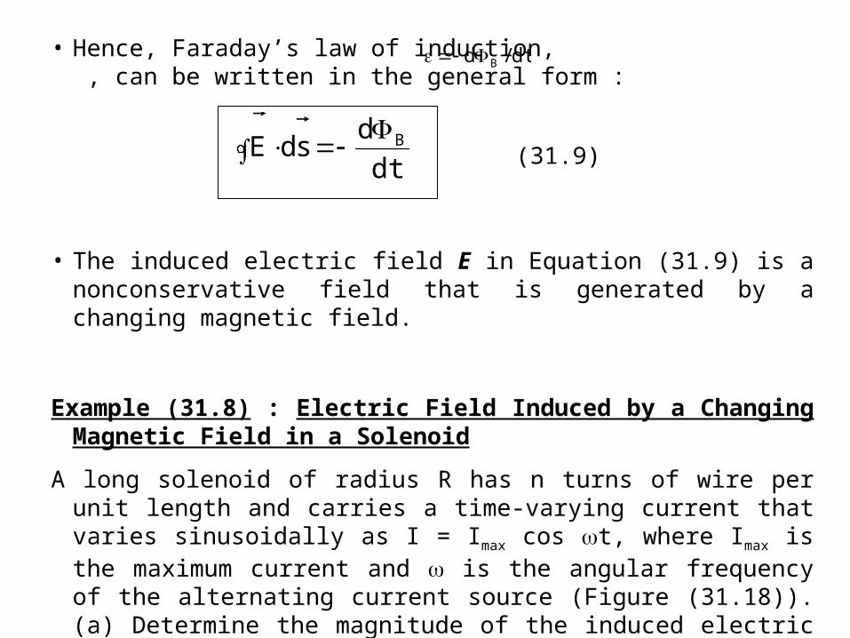
• Hence, Faraday’s law of induction, , can be written in the general form :
• The induced electric field E in Equation (31.9) is a nonconservative field that is generated by a changing magnetic field.
Example (31.8) : Electric Field Induced by a Changing Magnetic Field in a Solenoid
A long solenoid of radius R has n turns of wire per unit length and carries a time-varying current that varies sinusoidally as I = Imax cos t, where Imax is the maximum current and is the angular frequency of the alternating current source (Figure (31.18)). (a) Determine the magnitude of the induced electric field outside the solenoid, a distance r > R from its long central axis. (b) What is the magnitude of the induced elelctric field inside the solenoid, a distance r from its axis?
dt/d B
dt
dsdE B
(31.9)
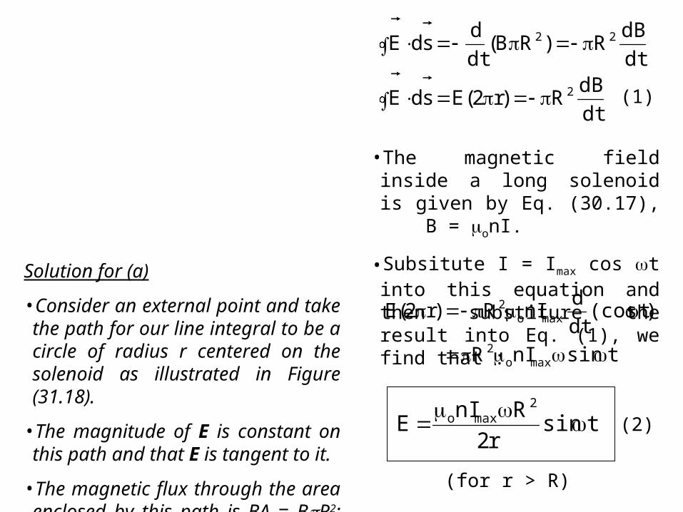
Solution for (a)
•Consider an external point and take the path for our line integral to be a circle of radius r centered on the solenoid as illustrated in Figure (31.18).
•The magnitude of E is constant on this path and that E is tangent to it.
•The magnetic flux through the area enclosed by this path is BA = BR2; hence, Eq. (31.9) gives :
•The magnetic field inside a long solenoid is given by Eq. (30.17), B = onI.
•Subsitute I = Imax cos t into this equation and then substiture the result into Eq. (1), we find that :
dt
dBR)r2(EsdE
dt
dBR)RB(
dt
dsdE
2
22
(1)
tsinnIR
)t(cosdt
dnIR)r2(E
maxo2
maxo2
tsinr2
RnIE
2maxo
(2)
(for r > R)
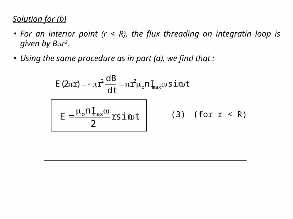
Solution for (b)
• For an interior point (r < R), the flux threading an integratin loop is given by Br2.
• Using the same procedure as in part (a), we find that :
tsinnIrdt
dBr)r2(E maxo
22
tsinr2
nIE maxo
(3) (for r < R)