chapter 31 faraday’s law electricity generator, or from b to e. 1.battery chemical emf 2.motional...
TRANSCRIPT

Chapter 31
Faraday’s Law
Electricity generator, or from B to E.1. Battery Chemical emf2. Motional emf3. Faraday’s Law of Induction4. Lentz Law about the emf direction

A dry-cell battery
Chemical reactions in the battery cells transport charge carriers (electrons) from one terminal to the other to create the needed electric potential (emf) to drive the current through the outside load, a light bulb here.

Motional emf, the conceptq F v B
q F v B
B EF qvB F qE
When equilibrium
WithWe can group charges by moving them in a magnetic field motional emf.
A motional emf is the emf induced in a conductor moving through a magnetic field
The electrons in the conductor experience a force, that is directed along ℓ
Charges are accumulated at the ends of the conductor to create an electric field inside the conductor to stop further charge transportation.
q F v B

Motional emf, the calculation Start from the equilibrium condition
One has
Or the emf, potential difference:
As long as the bar is kept being moved with a velocity v, the motional emf is maintained to be
vBℓ.
B EF qvB F qE
E vB
emf V E vBl l

Motional emf, put in use to power a resistor
PLAYACTIVE FIGURE
Bar moved by
appF
I
Two issues need attention:1. The moving bar carrying current I, inside the magnetic field,
experiences a force from the field is FB=IℓB2. The magnetic flux in the enclosed area (bar, rails and resistor) is
ΦB=xℓB, and it is changing with time as
Equivalent circuit diagram
Condition:A bar moving on two rails. The bar and the rails have negligible resistance. A resistor of R is connected to the end of the two rails. Result:The emf = vBℓ, so the current I = vBℓ /R
bd d dx
x B B vBdt dt dt
emfl l l

Example, what is the terminal velocity?A bar of mass m sides on two vertical rails. A resistor is connected to the end of the rails. When the bar is released at t = t0, (a) calculate the velocity of the bar at time t, (b) what is the terminal velocity? Assuming that the rails and the magnetic field is long/large enough. I
m
emf vBl
G ˆmgF x
Once the bar starts to move, accelerated by the gravitational force, there is:
And there is current as well:I vB Rl /
And there is magnetic force on the bar, pointing opposite to the gravitational force:
2
B
v BI ˆ ˆB
RF x x
ll

Example, what is the terminal velocity?
Im
G ˆmgF x
Construct the equation of velocity v:
Solve this equation
This is the answer to (a). For (b), the terminal velocity is when
2
2
G B
v Bmg m
v B dvmg m
dt
ˆR
R
F F axl
l
2
dv dt mR,
v g Bl
1 0 0t
v g e , v t
g t

Faraday’s Law of induction
In the sliding bar “experiment”, we proved that: bd
dtemf
We also know that the magnetic flux is defined as
cos
or B Bd BA θB A
In the sliding bar experiment, we changed A by moving the bar. More practically people change B or the angle θ to achieve a changing flux.
Changing B Changing θ

Faraday’s Law of induction
In any case, the induced emf follows the Faraday’s Law of induction
bd
dtemf
Yes, I sleeked in the “-”
in front of the bd
dt
Because Mr. Lenz told me so in order to answer the question of in which direction should the induced current flow.

Faraday’s Law – Statements
Faraday’s law of induction states that “the emf induced in a circuit is directly proportional to the time rate of change of the magnetic flux through the circuit”
Mathematically,
Bdε
dt
Lenz’s Law

Lenz’s Law, the direction of the induced emf
Lenz’s law: the induced current in a loop is in the direction that creates a magnetic field that opposes the change in magnetic flux through the area enclosed by the loop. The induced current tends to keep the original magnetic flux through the circuit from changing

Example: EMF produced by a changing magnetic field
A loop of wire is connected to a sensitive ammeter
Determine the current in the loop and the magnet is being Moved into the loop Moved out of the loop Held still inside the loop
PLAYACTIVE FIGURE

Example: a transformer A primary coil is connected to a
switch and a battery The wire is wrapped around an
iron ring A secondary coil is also
wrapped around the iron ring There is no battery present in
the secondary coil The secondary coil is not
directly connected to the primary coil
Close the switch and observe the current readings given by the ammeter
PLAYACTIVE FIGURE

Example, Lenz’s Law

Applications of Faraday’s Law – GFI A GFI (ground fault
indicator) protects users of electrical appliances against electric shock
When the currents in the wires are in opposite directions, the flux is zero
When the return current in wire 2 changes, the flux is no longer zero
The resulting induced emf can be used to trigger a circuit breaker

Applications of Faraday’s Law – Pickup Coil The pickup coil of an
electric guitar uses Faraday’s law
The coil is placed near the vibrating string and causes a portion of the string to become magnetized
When the string vibrates at some frequency, the magnetized segment produces a changing flux through the coil
The induced emf is fed to an amplifier

Rotating Loop
Assume a loop with N turns, all of the same area rotating in a magnetic field
The flux through the loop at any time t is
B = BA cos
= BA cos t
So
sin
Bdemf N NBAω ωt
dtThe emf is a sin wave: AC.
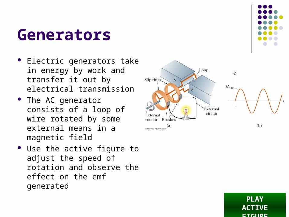
Generators
Electric generators take in energy by work and transfer it out by electrical transmission
The AC generator consists of a loop of wire rotated by some external means in a magnetic field
Use the active figure to adjust the speed of rotation and observe the effect on the emf generated
PLAYACTIVE FIGURE

DC Generators
The DC (direct current) generator has essentially the same components as the AC generator
The main difference is that the contacts to the rotating loop are made using a split ring called a commutator
Use the active figure to vary the speed of rotation and observe the effect on the emf generated
PLAYACTIVE FIGURE

Motors
Motors are devices into which energy is transferred by electrical transmission while energy is transferred out by work
A motor is a generator operating in reverse A current is supplied to the coil by a battery
and the torque acting on the current-carrying coil causes it to rotate

Motors, cont.
Useful mechanical work can be done by attaching the rotating coil to some external device
However, as the coil rotates in a magnetic field, an emf is induced This induced emf always acts to reduce the
current in the coil The back emf increases in magnitude as the
rotational speed of the coil increases

Motors, final
The current in the rotating coil is limited by the back emf The term back emf is commonly used to indicate
an emf that tends to reduce the supplied current The induced emf explains why the power
requirements for starting a motor and for running it are greater for heavy loads than for light ones

Eddy Currents
Circulating currents called eddy currents are induced in bulk pieces of metal moving through a magnetic field
The eddy currents are in opposite directions as the plate enters or leaves the field
Eddy currents are often undesirable because they represent a transformation of mechanical energy into internal energy

Eddy Currents, Example
The magnetic field is directed into the page
The induced eddy current is counterclockwise as the plate enters the field
It is opposite when the plate leaves the field
The induced eddy currents produce a magnetic retarding force and the swinging plate eventually comes to rest
PLAYACTIVE FIGURE

Eddy Currents, Final
To reduce energy loses by the eddy currents, the conducting parts can Be built up in thin layers
separated by a nonconducting material
Have slots cut in the conducting plate
Both prevent large current loops and increase the efficiency of the device
PLAYACTIVE FIGURE

Induced emf and Electric Fields
An electric field is created in the conductor as a result of the changing magnetic flux
Even in the absence of a conducting loop, a changing magnetic field will generate an electric field in empty space
This induced electric field is nonconservative Unlike the electric field produced by stationary
charges

Induced emf and Electric Fields, cont.
The emf for any closed path can be expressed as the line integral of over the path
Faraday’s law can be written in a general form:
Bdd
dt
E s
dE s

Induced emf and Electric Fields, final
The induced electric field is a nonconservative field that is generated by a changing magnetic field
The field cannot be an electrostatic field because if the field were electrostatic, and hence conservative, the line integral of would be zero and it isn’t
dE s