chapter 33 hdmi transmitter (hdmi) - freebsdgonzo/arm/imx6-hdmi.pdf · the video pixel sampler...
TRANSCRIPT
Chapter 33HDMI Transmitter (HDMI)
33.1 Overview
33.1.1 HDMI Operational Model OverviewThe High Definition Multimedia Interface (HDMI) is a wired digital interconnect thatreplaces the analog TV out or VGA out.
HDMI is capable of transferring uncompressed video, audio, and data using a singlecable. The video pixel rates are typically from 25 MHz up to 266 MHz (and 3D videomodes), but HDMI can support higher rates up to 266 MHz. It can support S/PDIF(IEC60958 L-PCM and IEC61937 compressed non-linear PCM: AC-3, MPEG-1/-2Audio, DTS®, MPEG-2/-4 AAC, ATRAC, WMA, MAT) and Parallel HBR (high bitrate) audio interface, enabling the support of Dolby® True-HD and DTS-HD MasterAudio. HDMI has the capability of automatically setting the display format configuration(intelligent link).
HDMI include a content protection system called HDCP (High-bandwidth Data ContentProtection). The HDMI connections can be used to connect DVD recorders, set-topboxes, and game consoles to flat panel televisions and an AV amplifier that can act asrepeater/router.
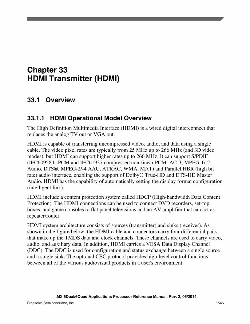
HDMI system architecture consists of sources (transmitter) and sinks (receiver). Asshown in the figure below, the HDMI cable and connectors carry four differential pairsthat make up the TMDS data and clock channels. These channels are used to carry video,audio, and auxiliary data. In addition, HDMI carries a VESA Data Display Channel(DDC). The DDC is used for configuration and status exchange between a single sourceand a single sink. The optional CEC protocol provides high-level control functionsbetween all of the various audiovisual products in a user's environment.
i.MX 6Dual/6Quad Applications Processor Reference Manual, Rev. 2, 06/2014
Freescale Semiconductor, Inc. 1545

CEC
HEAC
detect
HDMI Source HDMI Sink
TMDS Channel 0
TMDS Channel 1
TMDS Channel 2
TMDS Clock Channel
HDMIReceiver
Video
Audio
Control/Status
Video
Audio
Control/Status
HDMITransmitter
Display Data Channel (DDC)
CEC Line
Utility Line
HPD LineHigh/Low
HEAC
CEC
ROMEDID
Figure 33-1. HDMI Block Diagram
Audio, video, and auxiliary data is transmitted across the three TMDS data channels. ATMDS clock running at 1x (24-bit true color mode), the video pixel rate is transmitted onthe TMDS clock channel and used by the receiver as a frequency reference for datarecovery on the three TMDS data channels. Video data can have a pixel size of 24bits .Video at the default 24-bit color depth is carried at a TMDS clock rate equal to the pixelclock rate. Higher color depths are carried using a correspondingly higher TMDS clockrate. Video formats with TMDS rates below 25MHz (such as, 13.5MHz for 480i/NTSC)can be transmitted using a pixel-repetition scheme. The video pixels can be encoded ineither RGB, YCBCR 4:4:4, or YCBCR 4:2:2 formats.
HDMI uses a packet structure to transmit audio and auxiliary data across the TMDSchannels. To attain the highest reliability required of audio and control data, this data isprotected with a BCH error correction code and is encoded using a special error reductioncode to produce the transmitted 10-bit word.
Basic audio functionality consists of a single IEC 60958 L-PCM audio stream (two audiochannels) at sample rates of 32 KHz, 44.1 KHz, or 48 KHz, which can accommodate anynormal stereo stream. Optionally, HDMI can carry audio at sample rates up to 192KHz
Overview
i.MX 6Dual/6Quad Applications Processor Reference Manual, Rev. 2, 06/2014
1546 Freescale Semiconductor, Inc.
and with three to eight audio channels. HDMI can also carry an IEC 61937 compressed(such as, surround sound) audio stream at bit rates up to 24.576 Mbps. For bit rates above6.144 Mbps, compressed audio streams conforming to IEC 61937 are carried using HBRAudio Stream Packets. Each packet carries four IEC 60958 frames, which corresponds to(4x2x16 =) 128 contiguous bits of an IEC 61937 stream.
The source uses the DDC to read the sink's Enhanced Extended Display IdentificationData (E-EDID) to obtain the sink's configuration and/or capabilities.
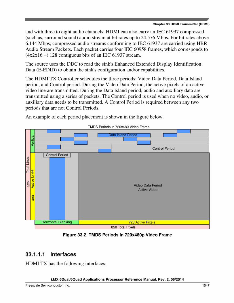
The HDMI TX Controller schedules the three periods: Video Data Period, Data Islandperiod, and Control period. During the Video Data Period, the active pixels of an activevideo line are transmitted. During the Data Island period, audio and auxiliary data aretransmitted using a series of packets. The Control period is used when no video, audio, orauxiliary data needs to be transmitted. A Control Period is required between any twoperiods that are not Control Periods.
An example of each period placement is shown in the figure below.
TMDS Periods in 720x480 Video Frame
Video Data PeriodActive Video
DataIslandPeriod
Control Period
Horizontal Blanking 720 Active Pixels858 Total Pixels
Data Island Period
Control Period
Horizontal Blanking
525
Tot
al L
ines
480
Act
ive
Line
sVe
rtic
al
Figure 33-2. TMDS Periods in 720x480p Video Frame
33.1.1.1 Interfaces
HDMI TX has the following interfaces:
Chapter 33 HDMI Transmitter (HDMI)
i.MX 6Dual/6Quad Applications Processor Reference Manual, Rev. 2, 06/2014
Freescale Semiconductor, Inc. 1547

• HDCP interface• External ROM interface for key storage• External RAM interface for revocation• Random number generator interface• Video input interface• RGB 4:4:4• YCbCr4:2:2• YCbCr4:4:4• Digital audio input interface• AHB audio DMA• System interface• AMBA AHB• Scan test interface• HDMI TX PHY interface• CEC interface
33.1.1.2 Features
HDMI TX includes the following features:
• Supported video formats:• All CEA-861-E video formats up to 1080p at 60Hz and 720p/1080i at 120Hz• Supported colorimetry:• 24bit RGB 4:4:4• 24bit YCbCr 4:4:4• 16bit YCbCr 4:2:2• xvYCC601• xvYCC709• Integrated color space converter:• RGB(4:4:4) to/from YCbCr(4:4:4 or 4:2:2)• Optional HDMI 1.4a supported video formats:• HDMI 1.4a 3D video modes with up to 266MHz (TMDS clock)• Optional HDMI 1.4a supported colorimetry:• sYCC601• Adobe RGB• Adobe YCC601• Optional HDMI 1.4a supported Infoframes:• Audio InfoFrame packet extension to support LFE playback level information• AVI infoFrame packet extension to support YCC Quantization range (Limited
Range, Full• Range)
Overview
i.MX 6Dual/6Quad Applications Processor Reference Manual, Rev. 2, 06/2014
1548 Freescale Semiconductor, Inc.
• AVI infoFrame packet extension to support Content type (Graphics, Photo, Cinema,Game)
• Supported Audio formats:• Up to four I2S interface for eight-channel Linear-PCM audio• S/PDIF interface for linear and non-linear PCM formats:
• AC-3• MPEG-1/-2 Audio• DTS• MPEG- 2/-4 AAC• ATRAC• WMA• MAT
• Parallel audio interface for High-Bit Rate (HBR) Audio:• Dolby® True-HD• DTS®-HD Master Audio• Generic Parallel Audio interface
• AHB DMA Audio interface• Up to 192 KHz IEC60958 audio sampling rate• Pixel clock from 13.5MHz up to 266 MHz• Option to remove pixel repetition clock (prepclk) from HDMI TX interface for an
easy integration with third-party HDMI TX PHYs• Flexible synchronous enable per clock domain to set functional power down modes• Register access:• AMBA AHB• I2C DDC, EDID block read mode• Advanced PHY testability• Integrated CEC hardware engine
33.2 External SignalsSee HDMI PHY for external signal information.
33.3 ClocksThe table found here describes the clock sources for HDMI.
Chapter 33 HDMI Transmitter (HDMI)
i.MX 6Dual/6Quad Applications Processor Reference Manual, Rev. 2, 06/2014
Freescale Semiconductor, Inc. 1549

Please see Clock Controller Module (CCM) for clock setting, configuration and gatinginformation.
Table 33-1. HDMI Clocks
Clock name Clock Root Description
iahbclk ahb_clk_root Bus clock
icecclk ckil_sync_clk_root CEC low-frequency clock (32kHZ)
ihclk ahb_clk_root Module clock
isfrclk video_27m_clk_root Internal SFR clock (video clock 27MHz)
33.4 Functional DescriptionThis section describes the functional architecture of the HDMI TX controller.
33.4.1 HDMI TX Functional OverviewThe HDMI TX provides a variety of standard audio, video, and system interfaces.
It includes an high-bandwidth data content protection (HDCP) encryption engine forHDMI receiver authentication, revocation, and data encryption.
Figure below illustrates the top level diagram of the HDMI TX solution.
Functional Description
i.MX 6Dual/6Quad Applications Processor Reference Manual, Rev. 2, 06/2014
1550 Freescale Semiconductor, Inc.

HDMI TX controller
VideoInterface
AudioInterface
ControlInterface
Video Sampler ColorSpace
Converter
VideoPacketizer
AudioPacketizer
FrameComposer
HDCPEncryptor
RegisterBank
Main ControlLogic
I2C Master
I2C/DDCMaster
CECController
DMA
Audio Sampler
AMBA AHB
Configuration&
Control
References
PLL
PLL
PLL
PLL
HDMI TX PHY
HDMI_TX_CLK_PHDMI_TX_CLK_N
HDMI_TX_DATA0_PHDMI_TX_DATA0_N
HDMI_TX_DDC_SCLHDMI_TX_DDC_SDA
HDMI_TX_DDC_CEC
HDMI_TX_DATA1_PHDMI_TX_DATA1_N
HDMI_TX_DATA2_PHDMI_TX_DATA2_N
Figure 33-3. HDMI TX Top Level Block Diagram
The HDCP encryption engine is responsible for HDMI receiver authentication,revocation, and data encryption.
The input video stream can be either RGB 4:4:4, YcbCr 4:2:2, or YcbCr 4:44 in singledata rate (SDR) bus formats as described in Table 33-2. The video mode's timing formatmust follow the CEA-861-E specification. An embedded color space conversion allowsthe pixel color format to be converted on the HDMI source side to match the best withthe HDMI sink capabilities. 24
The input audio stream can be provided through audio AHB DMA interface;
Finally, HDMI_TX can output video in full HD with up to 48-bit color mode and insertshigh fidelity audio up to eight-channels over low resolution video formats by performingautomatic pixel repetition over the input video stream.
33.4.2 Video Pixel SamplerThe Video pixel sampler block is responsible for the video data synchronization,according to the video data input mapping defined by the Color Depth (Deep Color) andformat configuration.
Chapter 33 HDMI Transmitter (HDMI)
i.MX 6Dual/6Quad Applications Processor Reference Manual, Rev. 2, 06/2014
Freescale Semiconductor, Inc. 1551

Optionally, for YCbCr 4:2:2 format, data mapping can be performed to conform to ITU.601 and ITU.656 standards but without the support of embedded synchronizers.
The video pixel sampler registers base address is 0x0200.
33.4.2.1 HDMI Transmitter Controller Databook FunctionalDescription
Table 33-2. Input Data Mapping
Video InputFormat
ivdata[47:0] mapping
ColorSpace
ColorDepth
47-46
45-44
43-42
41-40
39-38
37-35
35-34
33-32
31-30
29-28
27-26
25-24
23-22
21-20
19-18
17-16
15-14
13-12
11-10
9-8
7-6
5-4
3-2
1-0
RGB4:4:4
8-bit R[7:0] G[7:0] B[7:0]
YCbCr4:4:4
8-bit Cb[7:0] Y[7:0] Cr[7:0]
YCbCr4:2:2
8-bit Cb[7:0] Y[7:0]
Cr[7:0] Y[7:0]
For each video timing format, there is a specific timing parameters defined in theCEA-861-E specification.
The following timing diagram is an example for the video mode format 1 (640x480p @59.94/60 Hz): Data Enable = idataen, HSYNC = ihsync, VSYNC = ivsync.
Functional Description
i.MX 6Dual/6Quad Applications Processor Reference Manual, Rev. 2, 06/2014
1552 Freescale Semiconductor, Inc.

800 Total Horizontal Clocks per line
DataEnable
160 640 Clocks for Active Video
16 48 clocks
HSYNC
Progressive Frame: 45 Vertical Blanking Lines 480 Active Vertical Lines
DataEnable
HSYNC
VSYNC
16800 clocks 144
515 515 517 24 525 1 2 3 4 5 6 7 35 36 515 516 525
Figure 33-4. Timing Parameters for 640x480p @ 59.94/60 Hz
For a complete list of timing parameters and diagrams, refer to the CEA-861-Especification. The SDR video sample input format is illustrated in the figure below.
Chapter 33 HDMI Transmitter (HDMI)
i.MX 6Dual/6Quad Applications Processor Reference Manual, Rev. 2, 06/2014
Freescale Semiconductor, Inc. 1553

idataen
ipclk
idata Data N Data N + 1
Figure 33-5. Video Sample Timing Interface for RGB and YCbCr SDR Format
33.4.3 Supported Video ModeThe table below shows examples of the supported video modes.
Table 33-3. Video Modes
2D 3D Structure
VideoMode
Mode H x VActiveResolution (pixel)
Refres hRate(Hz)
2DPixelRate(Mp/s)
FramePacking PixelRate(Mp/s)
FieldAlt.PixelRate(Mp/s)
LineAlt.PixelRate(Mp/s)
Side-by-Side(full)PixelRate(Mp/s)
L+depthPixelRate(Mp/s)
L+depth+graphics+graphics-depthPixelRate(Mp/s)
Side-by-Side(Half)PixelRate(Mp/s)
Top-and-BottomPixelRate(Mp/s)
ALLCEA
Interlaced
Only
Progr.Only
ALLCEA
Progr.Only
Progr.Only
ALLCEA
ALLCEA
Primary HDMI Video Format Timings (CEA-861-E)
Table continues on the next page...
Functional Description
i.MX 6Dual/6Quad Applications Processor Reference Manual, Rev. 2, 06/2014
1554 Freescale Semiconductor, Inc.

Table 33-3. Video Modes (continued)
1 640x480p(EDTV)
640 x 480 59.94 25.18 50.35 50.35 50.35 50.35 100.70 25.18 25.18
1 60.00 25.2 50.40 50.40 50.40 50.40 100.80 25.2 25.2
19 1280x720p(HDTV)
1280 x720
50.00 74.25 148.50 148.50 148.50 148.50 297.00 74.25 74.25
4 59.94 74.18 148.35 148.35 148.35 148.35 296.70 74.18 74.18
4 60.00 74.25 148.50 148.50 148.50 148.50 297.00 74.25 74.25
20 1920x1080i(HDTV)
1920 x1080
50.00 74.25 148.50 148.50 148.50 74.25 74.25
5 59.94 74.18 148.35 148.35 148.35 74.18 74.18
5 60.00 74.25 148.50 148.50 148.50 74.25 74.25
2.3 720x480p(EDTV)
720 x 480 59.94 27.00 54.00 54.00 54.00 54.00 108.00 27.00 27.00
2.3 60.00 27.03 54.05 54.05 54.05 54.05 108.11 27.03 27.03
6.7 720(1440)x480i (SDTV)
1440 x480
59.94 27.00 54.00 54.00 54.00 27.00 27.00
6.7 60.00 27.03 54.05 54.05 54.05 27.03 27.03
17.18 720x576p(EDTV)
720 x 576 50.00 27.00 54.00 54.00 27.00 27.00
21.22 720(1440)x576i (SDTV)
1440 x576
50.00 27.00 54.00 54.00 54.00 27.00 27.00
Secondary HDMI video format timings (CEA-861-E)
8.9 720(1440)x240p
1440 x240
59.94 27.00 54.00 54.00 54.00 54.00 108.00 27.00 27.00
8.9 60.00 27.03 54.05 54.05 54.05 54.05 108.11 27.03 27.03
10.11 1440(2880)x480i
2880 x480
59.94 54.00 108.00 108.00 108.00 54.00 54.00
10.11 60.00 54.05 108.11 108.11 108.11 54.05 54.05
12.13 1440(2880)x240p
2880 x240
59.94 54.00 108.00 108.00 108.00 108.00 216.00 54.00 54.00
12.13 60.00 54.05 108.11 108.11 108.11 108.11 216.22 54.05 54.05
32 1920x1080p(HDTV)
1920 x1080
23.98 74.18 148.35 148.35 148.35 148.35 296.70 74.18 74.18
32 24.00 74.25 148.50 148.50 148.50 148.50 297.00 74.25 74.25
33 25.00 74.25 148.50 148.50 148.50 148.50 297.00 74.25 74.25
34 29.97 74.18 148.35 148.35 148.35 148.35 296.70 74.18 74.18
34 30.00 74.25 148.50 148.50 148.50 148.50 297.00 74.25 74.25
31 50.00 148.5 297.00 297.00 297.00 297.00 148.5 148.5
16 59.94 148.35
296.70 296.70 296.70 296.70 148.35 148.35
16 60.00 148.5 297.00 297.00 297.00 297.00 148.5 148.5
64 100.00
297.00
297.00 297.00
Table continues on the next page...
Chapter 33 HDMI Transmitter (HDMI)
i.MX 6Dual/6Quad Applications Processor Reference Manual, Rev. 2, 06/2014
Freescale Semiconductor, Inc. 1555
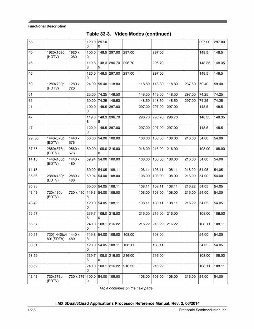
Table 33-3. Video Modes (continued)
63 120.00
297.00
297.00 297.00
40 1920x1080i(HDTV)
1920 x1080
100.00
148.5 297.00 297.00 297.00 148.5 148.5
46 119.88
148.35
296.70 296.70 296.70 148.35 148.35
46 120.00
148.5 297.00 297.00 297.00 148.5 148.5
60 1280x720p(HDTV)
1280 x720
24.00 59.40 118.80 118.80 118.80 118.80 237.60 59.40 59.40
61 25.00 74.25 148.50 148.50 148.50 148.50 297.00 74.25 74.25
62 30.00 74.25 148.50 148.50 148.50 148.50 297.00 74.25 74.25
41 100.00
148.5 297.00 297.00 297.00 297.00 148.5 148.5
47 119.88
148.35
296.70 296.70 296.70 296.70 148.35 148.35
47 120.00
148.5 297.00 297.00 297.00 297.00 148.5 148.5
29, 30 1440x576p(EDTV)
1440 x576
50.00 54.00 108.00 108.00 108.00 108.00 216.00 54.00 54.00
37.38 2880x576p(EDTV)
2880 x576
50.00 108.00
216.00 216.00 216.00 216.00 108.00 108.00
14.15 1440x480p(EDTV)
1440 x480
59.94 54.00 108.00 108.00 108.00 108.00 216.00 54.00 54.00
14.15 60.00 54.05 108.11 108.11 108.11 108.11 216.22 54.05 54.05
35.36 2880x480p(EDTV)
2880 x480
59.94 54.00 108.00 108.00 108.00 108.00 216.00 54.00 54.00
35.36 60.00 54.05 108.11 108.11 108.11 108.11 216.22 54.05 54.05
48.49 720x480p(EDTV)
720 x 480 119.88
54.00 108.00 108.00 108.00 108.00 216.00 54.00 54.00
48.49 120.00
54.05 108.11 108.11 108.11 108.11 216.22 54.05 54.05
56.57 239.76
108.00
216.00 216.00 216.00 216.00 108.00 108.00
56.57 240.00
108.11
216.22 216.22 216.22 216.22 108.11 108.11
50.51 720(1440)x480i (SDTV)
1440 x480
119.88
54.00 108.00 108.00 108.00 54.00 54.00
50.51 120.00
54.05 108.11 108.11 108.11 54.05 54.05
58.59 239.76
108.00
216.00 216.00 216.00 108.00 108.00
58.59 240.00
108.11
216.22 216.22 216.22 108.11 108.11
42.43 720x576p(EDTV)
720 x 576 100.00
54.00 108.00 108.00 108.00 108.00 216.00 54.00 54.00
Table continues on the next page...
Functional Description
i.MX 6Dual/6Quad Applications Processor Reference Manual, Rev. 2, 06/2014
1556 Freescale Semiconductor, Inc.
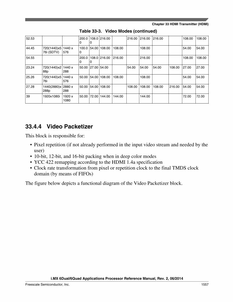
Table 33-3. Video Modes (continued)
52.53 200.00
108.00
216.00 216.00 216.00 216.00 108.00 108.00
44.45 720(1440)x576i (SDTV)
1440 x576
100.00
54.00 108.00 108.00 108.00 54.00 54.00
54.55 200.00
108.00
216.00 216.00 216.00 108.00 108.00
23.24 720(1440)x288p
1440 x288
50.00 27.00 54.00 54.00 54.00 54.00 108.00 27.00 27.00
25.26 720(1440)x576i
1440 x576
50.00 54.00 108.00 108.00 108.00 54.00 54.00
27.28 1440(2880)x288p
2880 x288
50.00 54.00 108.00 108.00 108.00 108.00 216.00 54.00 54.00
39 1920x1080i 1920 x1080
50.00 72.00 144.00 144.00 144.00 72.00 72.00
33.4.4 Video PacketizerThis block is responsible for:
• Pixel repetition (if not already performed in the input video stream and needed by theuser)
• 10-bit, 12-bit, and 16-bit packing when in deep color modes• YCC 422 remapping according to the HDMI 1.4a specification• Clock rate transformation from pixel or repetition clock to the final TMDS clock
domain (by means of FIFOs)
The figure below depicts a functional diagram of the Video Packetizer block.
Chapter 33 HDMI Transmitter (HDMI)
i.MX 6Dual/6Quad Applications Processor Reference Manual, Rev. 2, 06/2014
Freescale Semiconductor, Inc. 1557

Input_data
PixelRepeater
bypass_selector
default_phasefix_pp_to_lastcx_goto_p0pp_enpp_stuffing
output_selector
output_data
ycc422_sizeycc422_en
16, 20, 24YCC 422remap
10, 12, 16Packing PhaseFSM
PixelPacking
8-bit bypass
bypass en
Figure 33-6. Video Packetizer Functional Diagram
33.4.5 Color Space ConversionThis block is responsible for carrying out the following video color space conversionfunctions:
• RGB to/from YCbCr• 4:2:2 to/from 4:4:4 up (pixel repetition or linear interpolation)/down-converter• Limited to/from full quantization range conversion
Functional Description
i.MX 6Dual/6Quad Applications Processor Reference Manual, Rev. 2, 06/2014
1558 Freescale Semiconductor, Inc.
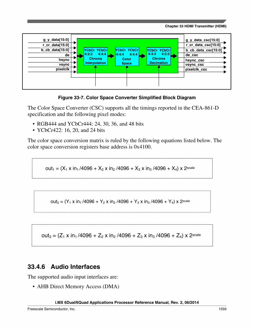
g_y_data[15:0]r_cr_data[15:0]
b_cb_data[15:0]de
hsyncvsync
pixelclk
g_y_data_csc[15:0]r_cr_data_csc[15:0]b_cb_data_csc[15:0]de_cschsync_cscvsync_cscpixelclk_csc
YCbCr YCbCr YCbCr YCbCr YCbCr YCbCr4:2:2 4:4:4 4:4:4 4:4:4 4:4:4 4:2:2
ChromaInterpolation
ColorSpace
ChromaDecimation
Figure 33-7. Color Space Converter Simplified Block Diagram
The Color Space Converter (CSC) supports all the timings reported in the CEA-861-Dspecification and the following pixel modes:
• RGB444 and YCbCr444: 24, 30, 36, and 48 bits• YCbCr422: 16, 20, and 24 bits
The color space conversion matrix is ruled by the following equations listed below. Thecolor space conversion registers base address is 0x4100.
out1 = (X1 x in1 /4096 + X2 x in2 /4096 + X3 x in3 /4096 + X4) x 2scale
out2 = (Y1 x in1 /4096 + Y2 x in2 /4096 + Y3 x in3 /4096 + Y4) x 2scale
out3 = (Z1 x in1 /4096 + Z2 x in2 /4096 + Z3 x in3 /4096 + Z4) x 2scale
33.4.6 Audio InterfacesThe supported audio input interfaces are:
• AHB Direct Memory Access (DMA)
Chapter 33 HDMI Transmitter (HDMI)
i.MX 6Dual/6Quad Applications Processor Reference Manual, Rev. 2, 06/2014
Freescale Semiconductor, Inc. 1559

No lipsync support is available inside the HDMI TX. If necessary, this feature can beperformed at the system audio processor side. From the HDMI TX, no audio/video delayor skew is added.
The audio sampler registers base address is 0x3100.
33.4.6.1 CTS Calculation
Because there is no audio clock carried through the HDMI link, only the pixel clock isused.
The CTS/N has to be set by software with value taken in the following table. Table belowshows the CTS and N value for the supported standard. All other TMDS clocks are notsupported; the TMDS clocks divided or multiplied by 1,001 coefficients are notsupported.
Table 33-4. N and CTS for 8-Bit Color Depth
TMDS Clock (MHz)
25.2 27 54 74.25 148.5 297
Fs(kHZ)
N CTS N CTS N CTS N CTS N CTS N CTS
32 4096 25200 4096 27000 4096 54000 4096 74250 4096 148500 3072 222750
44.1 6272 28000 6272 30000 6272 60000 6272 82500 6272 165000 4704 247500
48 6144 25200 6144 27000 6144 54000 6144 74250 6144 148500 5120 247500
88.2 12544 28000 12544 30000 12544 60000 12544 82500 12544 165000 9408 247500
96 12288 25200 12288 27000 12288 54000 12288 74250 12288 148500 10240 247500
176.4 25088 28000 25088 30000 25088 60000 25088 82500 25088 165000 18816 247500
192 24576 25200 24576 27000 24576 54000 24576 74250 24576 148500 20480 247500
768 Used for HBR audio only. N and CTS configured for Fs=192kHZ (1/4th ACR value per spec)
To support the deep color mode and/or 3D video modes, the TMDS clock is multipliedby 4, 2, 1.5, or 1.25, depending on the mode. In this case, the CTS value must also followthe same ratio.
33.4.6.2 Audio DMA Interface
This audio direct memory access (DMA) interface is intended for advanced systemsrunning 32-bit CPU SoC solutions.
Functional Description
i.MX 6Dual/6Quad Applications Processor Reference Manual, Rev. 2, 06/2014
1560 Freescale Semiconductor, Inc.
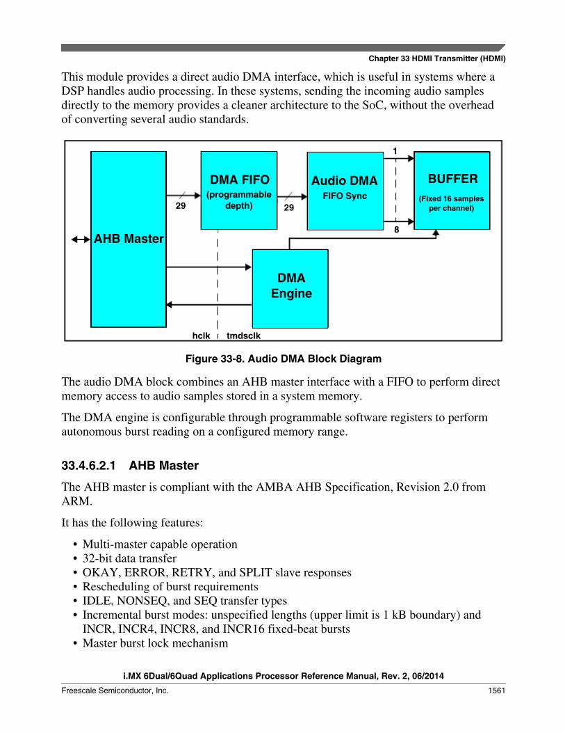
This module provides a direct audio DMA interface, which is useful in systems where aDSP handles audio processing. In these systems, sending the incoming audio samplesdirectly to the memory provides a cleaner architecture to the SoC, without the overheadof converting several audio standards.
AHB Master
DMA FIFO(programmable
depth)
Audio DMAFIFO Sync
DMAEngine
29 29
1
8
hclk tmdsclk
BUFFER(Fixed 16 samples
per channel)
Figure 33-8. Audio DMA Block Diagram
The audio DMA block combines an AHB master interface with a FIFO to perform directmemory access to audio samples stored in a system memory.
The DMA engine is configurable through programmable software registers to performautonomous burst reading on a configured memory range.
33.4.6.2.1 AHB Master
The AHB master is compliant with the AMBA AHB Specification, Revision 2.0 fromARM.
It has the following features:
• Multi-master capable operation• 32-bit data transfer• OKAY, ERROR, RETRY, and SPLIT slave responses• Rescheduling of burst requirements• IDLE, NONSEQ, and SEQ transfer types• Incremental burst modes: unspecified lengths (upper limit is 1 kB boundary) and
INCR, INCR4, INCR8, and INCR16 fixed-beat bursts• Master burst lock mechanism
Chapter 33 HDMI Transmitter (HDMI)
i.MX 6Dual/6Quad Applications Processor Reference Manual, Rev. 2, 06/2014
Freescale Semiconductor, Inc. 1561

• Bus access granting• The following features are not supported:• Write transaction• Protection control• BUSY transfer type• Wrapping burst
Data Organization in System Memory
The AHB master block fetches the samples from system memory. The Audio Samplesare organized according to the channel allocation.
For example, channel 0, 1, 3, 5 are enabled (0 and 1 are always enabled). The AudioSamples must be organized in the system memory like the following:
Table 33-5. Audio Sample Arrangement in System Memory
Position Sample Channel
0 n-1 0
1 n-1 1
2 n-1 3
3 n-1 5
4 n-1 0
5 n-1 1
6 n-1 3
7 n-1 5
... ... ...
Table 33-6. Data Arrangement in System Memory for L-PCM (24 bits)
Bit Description
28 B - IEC B bit
27 P - Parity bit
26 C - Channel Status bit
25 U - User Data bit
24 V - Validity Bit
[23:0] Audio Sample Data
Table 33-7. Data Arrangement in System Memory for L-PCM (16 bits) and NL-PCM (16 bits)
Bit Description
28 B - IEC B bit
27 P - Parity bit
26 C - Channel Status bit
Table continues on the next page...
Functional Description
i.MX 6Dual/6Quad Applications Processor Reference Manual, Rev. 2, 06/2014
1562 Freescale Semiconductor, Inc.

Table 33-7. Data Arrangement in System Memory for L-PCM (16 bits) and NL-PCM (16 bits)(continued)
25 U - User Data bit
24 V - Validity Bit
[23:8] Audio Sample Data
[7:0] 0x00
33.4.6.2.2 DMA Engine
The DMA engine is responsible for requesting burst transfers to the AHB master, takinginto account the FIFO threshold and register settings.
33.4.6.2.2.1 Functional Behavior
The engine:
• Arbitrates read requests to start the burst in the initial address with the size sufficientto fill the FIFO (the size of the FIFO is a parameter in the audio DMA core).
• After this first request, the DMA engine performs subsequent burst requests(incrementing accordingly ohaddr[31:0] and determining correct ohburst[2:0])towards final_addr[31:0] configured at the register bank and taking into account theAUDIO_FIFO_DEPTH parameter and fifo_threshold[7:0] configuration.
• In the burst mode (INCR4, INCR8, INCR16), the operation stops at the end of theburst.
• Stops operation upon ERROR slave response, signaling ointerror interrupt andstaterror signal
• Continues burst transaction:• Upon RETRY/SPLIT slave response, signaling ointretrysplit interrupt and
statretrysplit signal• Upon losing ownership (no ihgrant) as consequence of arbiter action, signaling
ointlostownership interrupt and statlostownership signal• Decides through register configuration which burst method (unspecified length
incrementing or fixed beat incrementing) to use in the read transfers• Issues ointdone interrupt when it reaches final address reading or is stopped upon
user request• Automatically starts new burst requests until the final_addr[31:0] is reached• The DMA engine is either stopped by the user or an error/fail condition appears at
the slave response.• Takes into account that an incrementing burst can be of any length (if unspecified
INCR type), but upper limit is set because the address must not cross a 1kB boundary
Chapter 33 HDMI Transmitter (HDMI)
i.MX 6Dual/6Quad Applications Processor Reference Manual, Rev. 2, 06/2014
Freescale Semiconductor, Inc. 1563

• A maximum theoretical length of a burst is 1024. The burst size must be declared onthe mburstlength_addr[10:0].
• Has INCR with an unspecified burst as the default operation burst mode
33.4.6.2.2.2 DMA Operation
Normal operation of the DMA engine is as follows:
1. The enable_hlock, incr_type[1:0], burst_mode, fifo_threshold[7:0],initial_addr[31:0], and final_addr[31:0] are configured according to desired DMAoperation.
NOTEConfigured values have to follow these rules:
The number of memory positions (between initial_addr and final_addr) has to be amultiple of theactive audio channels.
The final_addr[31:0] signal is always bigger than the initial_addr[31:0].
2. To start the audio DMA operation, a '1' is written to data_buffer_ready.3. The DMA engine starts the operation. The first burst transfer is:
ohaddr[31:0] = initial_addr[31:0]; ohburst[2:0] = INCR; mburstlength[10:0] = ((initial_addr[31:0] + AUDIO_FIFO_DEPTH) <= final_addr[31:0]) ? ((AUDIO_FIFO_DEPTH < 1024) ? AUDIO_FIFO_DEPTH : 1024) : (final_addr[31:0] -initial_addr[31:0]);
4. While DMA is reading samples from the AHB master and writing samples to theAudio FIFO, a datafetch request from the internal frame composer block mighthappen at the Audio FIFO interface, diminishing the number of samples in the FIFO.
5. When the number of samples in the Audio FIFO is lower than the configuredfifo_threshold[7:0], the DMA engine requests a new burst request to the AHB masterinterface with:
ohaddr[15:0] = last address in step 5);
ohburst[2:0] = INCR;
mburstlength[10:0] = AUDIO_FIFO_DEPTH - fifo_threshold[7:0];
6. Steps 4) and 5) continue until the final_addr[31:0] is reached.
Functional Description
i.MX 6Dual/6Quad Applications Processor Reference Manual, Rev. 2, 06/2014
1564 Freescale Semiconductor, Inc.
NOTEIn the last burst request, the DMA engine calculates themburstlength[10:0] such that the last requested readposition is the final_addr[31:0].
7. After completion of the DMA operation, the DMA engine issues the ointdoneinterrupt signaling end of operation.
Variations of the DMA engine's behavior occur when fixed-beat, incremental bursts areused by INCR4/INCR8/INCR16 burst selects. When this forcing mode is used, you mustcorrectly configure the FIFO's threshold such that the last of the consecutive INCRx(with x = 4, 8, or 16) bursts correctly fill the FIFO at last burst received. Note there is are-alignment at the 1k boundary.
The following are exceptions to the described DMA behavior:
1. When a user requests end stop_dma_transaction, the DMA engine stops at the end ofthe current burst operation and signals its completion with an ointdone interrupt.
2. When the AHB slave sends an error response, the DMA engine stops the currentoperation and signals ointerror interrupt.
Rules for Configuration of Address Registers:
1. Configure the last 2 bits of initial_addr with 0.
For example, 32’h0000_0000.
2. Configure the last 2 bits of final_addr with non-zero values.
For example
32’hxxx_xxx3 or
32’hxxx_xxx7 or
32’hxxx_xxxB or
32’hxxx_xxxF
Where x= any value
3. The number of samples is calculated by using the following formula:
Number of samples = (final_addr - initial_addr + 1) / 4
Therefore, final_addr = (Number of samples x 4) + initial_addr -1
If a defined length burst is used, align initial_addr, final_addr and fifo_threshold with the value. If
the burst is not aligned, DMA uses AHB INCR transfers when required.
Chapter 33 HDMI Transmitter (HDMI)
i.MX 6Dual/6Quad Applications Processor Reference Manual, Rev. 2, 06/2014
Freescale Semiconductor, Inc. 1565

Then the number of samples = 100 (a multiple of 5)
4. The threshold must be
Greater than the selected FIFO DEPTH; Greater than the number of channels enabled in channel allocation.
Due to the limit of audio DMA design, some registers configuration are updated bySDMA (Smart Direct Memory Access). SDMA need to do these items below:
1. clear the audio DMA done request(actually it’s an interrupt); set offset 0x00120109-- bit2.
2. configure next audio DMA start address(offset 0x00123604~0x00123607) and nextstop address(offset 0x00123608~0x0012360b); Start address and stop address areprovided by S/W and it’s variable.
3. Set offset 0x00123601 – bit0 “1” to start DMA;
33.4.6.2.2.3 Transfer Data, Package, and Word
One transfer data can be composed of several transfer packages, and one transfer packagecan be composed of one or several transfer bursts. One transfer burst can be composed ofseveral transfer words.
The figure below shows the transfer data structure for a fixed-beat, incremental burst.
burst1 burst2 burstN
Package 1 Package M
. . .
word1 word2 wordL
burst1 burst2 burstN. . .. . .
. . .
L = 4(for INCR4), 8(INCR8), 16(INCR16)
Figure 33-9. Transfer Data Constitution for Fixed-Beat, Incremental Burst
The figure below depicts the transfer data structure for an unspecified burst length.
Functional Description
i.MX 6Dual/6Quad Applications Processor Reference Manual, Rev. 2, 06/2014
1566 Freescale Semiconductor, Inc.

burst1 . . . burst1
Package MPackage 1
word1 word2 . . . wordL
L = unspecified number for INCR
Figure 33-10. Transfer Data Constitution for Unspecified Burst Length
The figure below illustrates the DMA state machine.
DMA XFER
DMA ERRDMA REQ
DMA IDLE
DMA STOP
When on pkg xter finishedor lost ownership
On Error Condition
Next Cycle
Next Cycle
When stop_dma_transactionasserted or final address reached
Required TransferInformation(addr, pkg length, etc.)
data_buffer_ready
Figure 33-11. DMA FSM Diagram
1. When the operation request is written into the data_buffer_ready, the state switchesfrom IDLE to DMAREQ.
2. When enough transfer information is ready, the state changes to DMAXFER.
Chapter 33 HDMI Transmitter (HDMI)
i.MX 6Dual/6Quad Applications Processor Reference Manual, Rev. 2, 06/2014
Freescale Semiconductor, Inc. 1567

3. When one package is completed-indicated by "OnePackOver"-or a lost ownershipoccurs, the state jumps back to DMAREQ, so the new transaction information can becalculated.
4. When the DMA is ready again, it jumps to DMAXFER.
The previous steps continue until you request an end operation or until the wholeoperation is completed.
33.4.6.2.3 Audio FIFO
This block contains a FIFO with a configurable depth.
The statthrfiffoempty flag is a version of the FIFO empty, that is active whenever theamount of samples in the FIFO is smaller than four samples. The AHB_DMA_THRSLDand the statthrfifoempty indicators are different. The AHB_DMA_THRSLD defines theoccupation of the FIFO, while statthrfifoempty helps the HDMI TX's Frame Composer inthe audio packet composition (required when non-linear audio is being packed, in whichcase four pair of samples are needed to compose one packet).
33.4.6.2.4 FIFO Occupancy/FIFO Almost Empty Flags
The FIFO depth is configured by setting the AUDIO_FIFO_DEPTH parameter incoreConsultant. The FIFO occupancy is calculated from the pointer values.
Also, the most significant pointer bits are used to perform the following calculation:
occupancy = wrptr[n-1:0] - rdptr_previous[n-1:0], if wrptr > rdptr_previous
occupancy = AUDIO_FIFO_DEPTH + wrptr[n-1:0] - rdptr_previous[n-1:0], if wrptr < rdptr_previous
If occupancy is less than 4, then statthrfifoempty is active.
An example of full/empty flags and FIFO occupancy is shown in the figure below.
Functional Description
i.MX 6Dual/6Quad Applications Processor Reference Manual, Rev. 2, 06/2014
1568 Freescale Semiconductor, Inc.

Have data
inside
No data inside
Normalcondition
IF WriteWill FULL
IF Read Will EMPTY
IF Read will threshold EMPTY
Occupancy Below
threshold
FIFO_RP
FIFO_RP
FIFO_RP FIFO_RP
FIFO_RP
FIFO_WP
FIFO_WP
FIFO_WP
FIFO_WP
FIFO_WP
N
0
Figure 33-12. Audio FIFO Status Indication
33.4.7 Supported Audio FormatsThe HDMI TX has several audio interfaces and each of them has different audio formatsupport capabilities.
Table below represents the audio interface and format dependencies.
Table 33-8. Supported Audio Formats
Audio Input Interface Audio Format Supported
Audio DMA Up to eight channels L-PCM/NL-PCM and HBR audio, allowing all audio formats listedto support one single audio DMA interface.
33.4.8 Frame ComposerThis block is responsible for assembling video, audio, and data packets in a consistentframe that are streamed to the HDCP cipher and then finally to the HDMI TX PHY.
Chapter 33 HDMI Transmitter (HDMI)
i.MX 6Dual/6Quad Applications Processor Reference Manual, Rev. 2, 06/2014
Freescale Semiconductor, Inc. 1569
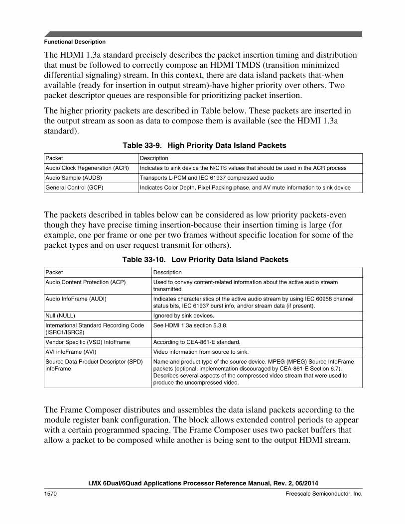
The HDMI 1.3a standard precisely describes the packet insertion timing and distributionthat must be followed to correctly compose an HDMI TMDS (transition minimizeddifferential signaling) stream. In this context, there are data island packets that-whenavailable (ready for insertion in output stream)-have higher priority over others. Twopacket descriptor queues are responsible for prioritizing packet insertion.
The higher priority packets are described in Table below. These packets are inserted inthe output stream as soon as data to compose them is available (see the HDMI 1.3astandard).
Table 33-9. High Priority Data Island Packets
Packet Description
Audio Clock Regeneration (ACR) Indicates to sink device the N/CTS values that should be used in the ACR process
Audio Sample (AUDS) Transports L-PCM and IEC 61937 compressed audio
General Control (GCP) Indicates Color Depth, Pixel Packing phase, and AV mute information to sink device
The packets described in tables below can be considered as low priority packets-eventhough they have precise timing insertion-because their insertion timing is large (forexample, one per frame or one per two frames without specific location for some of thepacket types and on user request transmit for others).
Table 33-10. Low Priority Data Island Packets
Packet Description
Audio Content Protection (ACP) Used to convey content-related information about the active audio streamtransmitted
Audio InfoFrame (AUDI) Indicates characteristics of the active audio stream by using IEC 60958 channelstatus bits, IEC 61937 burst info, and/or stream data (if present).
Null (NULL) Ignored by sink devices.
International Standard Recording Code(ISRC1/ISRC2)
See HDMI 1.3a section 5.3.8.
Vendor Specific (VSD) InfoFrame According to CEA-861-E standard.
AVI infoFrame (AVI) Video information from source to sink.
Source Data Product Descriptor (SPD)infoFrame
Name and product type of the source device. MPEG (MPEG) Source InfoFramepackets (optional, implementation discouraged by CEA-861-E Section 6.7).Describes several aspects of the compressed video stream that were used toproduce the uncompressed video.
The Frame Composer distributes and assembles the data island packets according to themodule register bank configuration. The block allows extended control periods to appearwith a certain programmed spacing. The Frame Composer uses two packet buffers thatallow a packet to be composed while another is being sent to the output HDMI stream.
Functional Description
i.MX 6Dual/6Quad Applications Processor Reference Manual, Rev. 2, 06/2014
1570 Freescale Semiconductor, Inc.

Packet requests are inserted into the packet queues by a data island flexible scheduler.The HDMI 1.3a specification requires that packet distribution and insertion timingcorrectly compose an output HDMI TMDS stream. In this context, there are data islandpackets that are sent on data availability, while others are sent once per frame or once pertwo frames. and finally others that are sent on user request. Classification of the packetsaccording to this insertion timing is described in the table below.
Table 33-11. Packet Classification
Packet Classification
Audio Clock Regeneration (ACR) Sent on data availability.
Audio Sample (AUDS) Sent on data availability (precede ACR if present).
Audio Content Protection (ACP) On user request or automatic insertion.
Audio InfoFrame (AUDI) Once per two frames.
Null (NULL) On user request or automatic insertion to fill Data Island period.
General Control (GCP) Once per frame.
International Standard Recording Code (ISRC1/ISRC2)
On user request.
Vendor Specific (VSD) InfoFrame On user request or automatic insertion.
AVI infoFrame (AVI) Once per frame.
Source Data Product Descriptor (SPD) infoFrame On user request or automatic insertion.
The Data Island Scheduler (DIS) handles packet distribution in the Frame Composer. TheDIS is a round- robin (RDRB) state machine that is able to schedule packet insertion onan input video frame or line basis. The DIS is fully configurable and can schedule anypacket type to be inserted at a given input video frame rate or input video line rate.
While determining packet distribution on an input video frame or line basis, the DISschedules the packets to be inserted in the output HDMI stream by inserting the packetdescriptor in the corresponding packet priority queue, according to packet priorityclassification.
After the packet descriptor has been inserted in the packet priority queues, the DataIsland Packer (DIP) is responsible for assembling and sequencing the packets for outputHDMI stream insertion.
Dedicated ECC generators and checksum byte-wide sum hardware generate the BCHECC parity codes and infoFrames checksums for all the data islands packets.
The content of GCP, ISRC1/2, VSD, AVI, SPD, and MPEG packets are configuredthrough the registers bank starting at address 0x1000.
Chapter 33 HDMI Transmitter (HDMI)
i.MX 6Dual/6Quad Applications Processor Reference Manual, Rev. 2, 06/2014
Freescale Semiconductor, Inc. 1571

33.4.9 HDCP Encryption EngineHDCP is designed to protect the transmission of audio-visual content between an HDCPTransmitter and an HDCP Receiver.
The system also allows for HDCP Repeaters that support downstream HDCP-protectedinterface ports. The HDCP system allows up to seven levels of HDCP Repeaters and asmany as 128 total HDCP devices, including HDCP Repeaters, to be attached to anHDCP-protected interface port.
NOTEThis feature must be configured and requires a separate license.Contact your Freescale representative for more information onHDCP.
The authentication protocol enables the HDCP Transmitter to verify that a given HDCPReceiver is licensed. With the legitimacy of the Receiver determined, encrypted HDCPcontent is transmitted between the two based on shared secrets established duringauthentication. In the event that legitimate devices are compromised to permitunauthorized use of the content, renewability allows an HDCP Transmitter to identifysuch compromised devices and prevent the transmission of the content.
The implemented HDCP functionality is compliant with HDCP revision 1.4. The HDCPtransmitter implements the three layers of the HDCP cipher, including LFSR and otherfunctions required to generate the encryption key bytes that are then XORed with thedata.
33.4.10 EDID/HDCP I2C E-DDC InterfaceThe E-DDC channel is a dedicated I2C master interface that allows the read of sink E-EDID based on system needs.
Data read from sink E-EDID can be then transferred to the I2C Master register bank,starting at address 0x7E00.
This block reads the E-EDID (and all its segments according to user configuration) and,after completion, it warns the CPU of data availability. This block also arbitrates the I2Cmaster interface to allow the HDMI TX's HDCP authentication protocol to be performedthrough this interface. Sink HDCP links (with addresses 0x74 and/or 0x76) should bepresent at these lines to enable HDCP-compliant behavior.
The interface is shared with the DDC channel of the HDMI controller throughmultiplexers and is I2C compliant.
Functional Description
i.MX 6Dual/6Quad Applications Processor Reference Manual, Rev. 2, 06/2014
1572 Freescale Semiconductor, Inc.

33.4.10.1 I2C Master Interface Normal Mode
This operation implements a single read or write operation using the Special FunctionRegister configuration.
The I2C data transfer protocol used is the 7-bit addressed, as defined in Section 9 of theI2C-bus Specification, version 2.1.
Transaction from slave to master
Transaction from master to slave
slaveaddr[6:0]S W A addr[7:0] datao[7:0] A/A PA/A
Legend:
A - Acknowledge (sdao low)
A - not Acknowledge (sdao high)
S - Start condition
P - Stop condition
W - Write indication
Figure 33-13. Data Write Transaction
Legend:
Transaction from master to slave
Transaction from slave to master
W A A/A A A Pdatai[7:0]slaveddr[6:0]addr[7:0]Slaveaddr[6:0] Sr R
A - Acknowledge (sdao low)
A - not Acknowledge (sdao high)
S - Start condition
Sr - Repeated start condition
P - Stop condition
W - Write indication
R - Read indication
S
Figure 33-14. Data Read Transaction
Chapter 33 HDMI Transmitter (HDMI)
i.MX 6Dual/6Quad Applications Processor Reference Manual, Rev. 2, 06/2014
Freescale Semiconductor, Inc. 1573
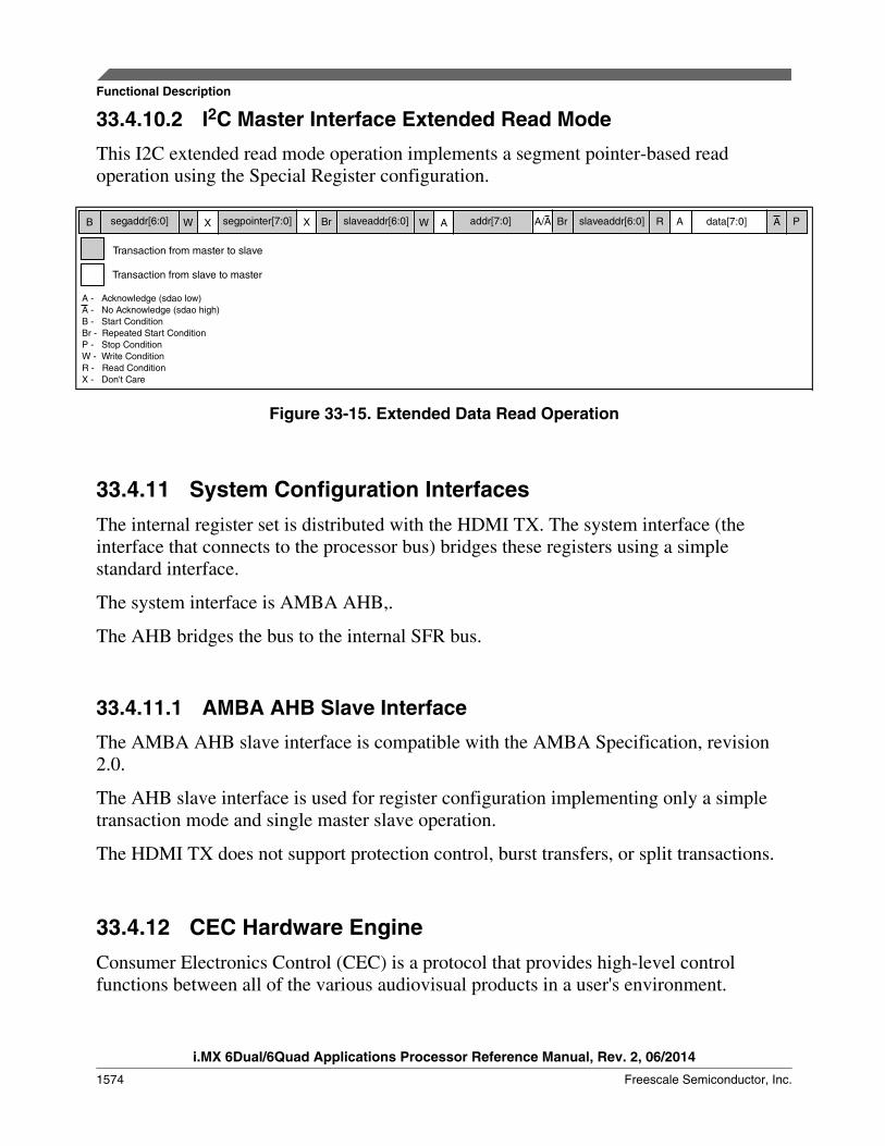
33.4.10.2 I2C Master Interface Extended Read Mode
This I2C extended read mode operation implements a segment pointer-based readoperation using the Special Register configuration.
A - Acknowledge (sdao low)A - No Acknowledge (sdao high)B - Start ConditionBr - Repeated Start ConditionP - Stop ConditionW - Write ConditionR - Read ConditionX - Don't Care
Transaction from master to slave
Transaction from slave to master
PAdata[7:0]ARBrA/Aaddr[7:0]AWBrXsegpointer[7:0]XWsegaddr[6:0]B slaveaddr[6:0] slaveaddr[6:0]
Figure 33-15. Extended Data Read Operation
33.4.11 System Configuration InterfacesThe internal register set is distributed with the HDMI TX. The system interface (theinterface that connects to the processor bus) bridges these registers using a simplestandard interface.
The system interface is AMBA AHB,.
The AHB bridges the bus to the internal SFR bus.
33.4.11.1 AMBA AHB Slave Interface
The AMBA AHB slave interface is compatible with the AMBA Specification, revision2.0.
The AHB slave interface is used for register configuration implementing only a simpletransaction mode and single master slave operation.
The HDMI TX does not support protection control, burst transfers, or split transactions.
33.4.12 CEC Hardware EngineConsumer Electronics Control (CEC) is a protocol that provides high-level controlfunctions between all of the various audiovisual products in a user's environment.
Functional Description
i.MX 6Dual/6Quad Applications Processor Reference Manual, Rev. 2, 06/2014
1574 Freescale Semiconductor, Inc.

It is an optional feature in the HDMI 1.3a Specification. It uses only one bidirectionalline for transmission and reception.
All transactions on the CEC line consist of an initiator and one or more followers. Theinitiator is responsible for sending the message structure and the data. The follower is therecipient of any data and is responsible for setting any acknowledgement bits.
ocecout
icecin CECEngine
RegisterBank
Configuration
Figure 33-16. CEC Engine Simplified Block Diagram
There are two operation modes for a CEC controller.
• Initiator Mode• In this mode, the CEC controller sends messages out and waits for a follower to
feedback. The CEC controller works in this mode when it starts to send a frame.After the transmission is done, it automatically returns to the follower mode (nosoftware control involved).
Chapter 33 HDMI Transmitter (HDMI)
i.MX 6Dual/6Quad Applications Processor Reference Manual, Rev. 2, 06/2014
Freescale Semiconductor, Inc. 1575
• Follower Mode• In this mode, the CEC controller receives messages and feeds back the initiator with
appropriate signals. The CEC controller always works in the follower modewhenever it is not transmitting any data.
For correct CEC controller interface operation, initial reset is required in order to setinternal registers to a known state. After this reset, the interface is in an IDLE state,waiting for a read or write request coming from the register configuration.
A specific CEC API is provided that implements all necessary low-level registerconfiguration to send and receive CEC messages. For more information, see the CECAPI documentation.
The CEC engine registers base address is 0x7D00. For more information about theseregisters, see HDMI Memory Map/Register Definition.
For more information about CEC, see Consumer Electronics Control (CEC) ApplicationNote.
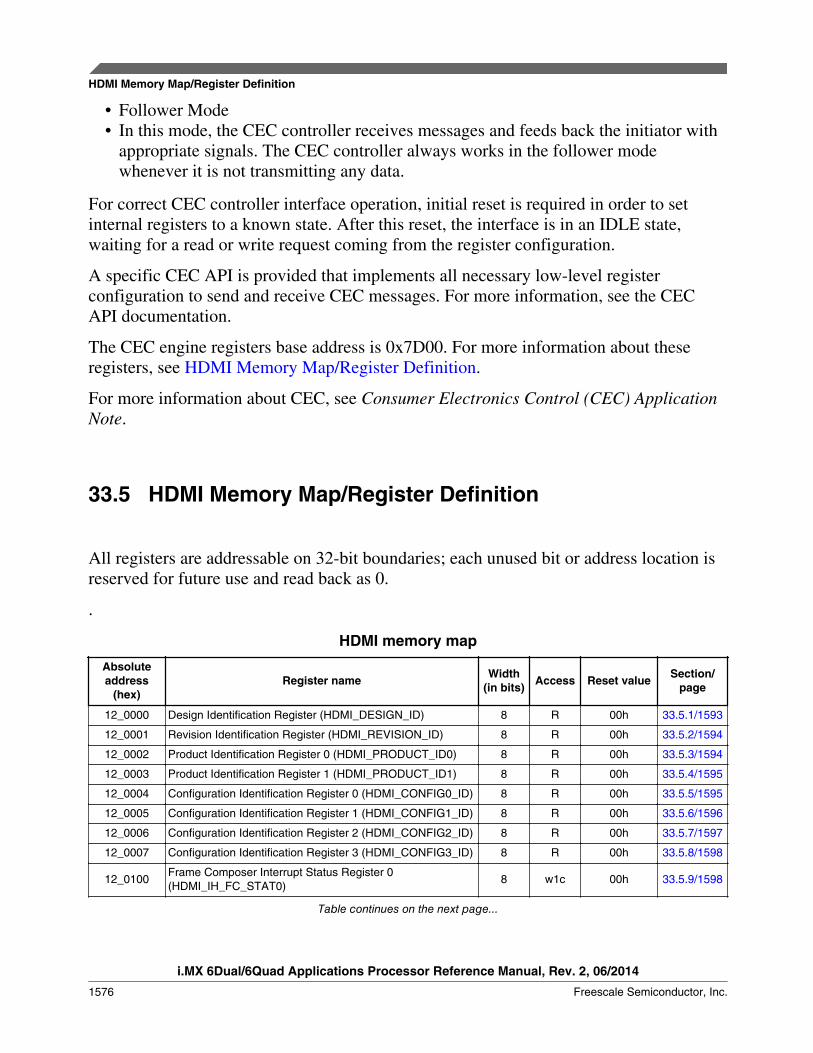
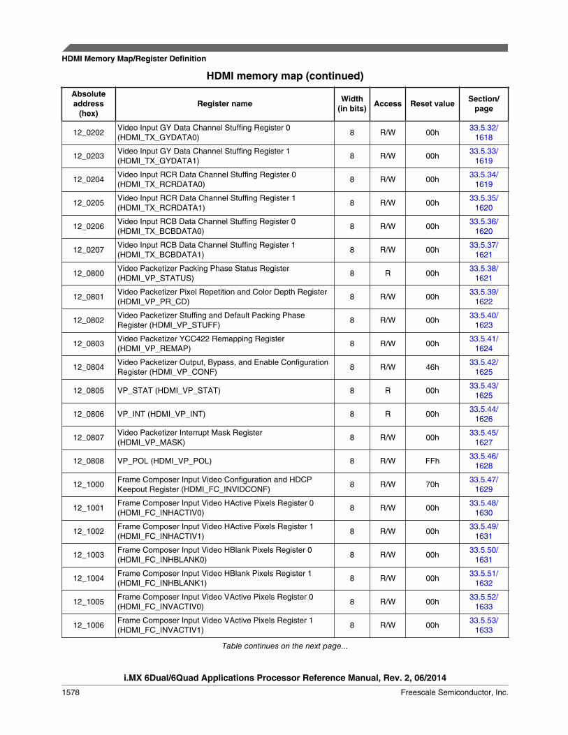
33.5 HDMI Memory Map/Register Definition
All registers are addressable on 32-bit boundaries; each unused bit or address location isreserved for future use and read back as 0.
.
HDMI memory map
Absoluteaddress
(hex)Register name Width
(in bits) Access Reset value Section/page
12_0000 Design Identification Register (HDMI_DESIGN_ID) 8 R 00h 33.5.1/1593
12_0001 Revision Identification Register (HDMI_REVISION_ID) 8 R 00h 33.5.2/1594
12_0002 Product Identification Register 0 (HDMI_PRODUCT_ID0) 8 R 00h 33.5.3/1594
12_0003 Product Identification Register 1 (HDMI_PRODUCT_ID1) 8 R 00h 33.5.4/1595
12_0004 Configuration Identification Register 0 (HDMI_CONFIG0_ID) 8 R 00h 33.5.5/1595
12_0005 Configuration Identification Register 1 (HDMI_CONFIG1_ID) 8 R 00h 33.5.6/1596
12_0006 Configuration Identification Register 2 (HDMI_CONFIG2_ID) 8 R 00h 33.5.7/1597
12_0007 Configuration Identification Register 3 (HDMI_CONFIG3_ID) 8 R 00h 33.5.8/1598
12_0100Frame Composer Interrupt Status Register 0(HDMI_IH_FC_STAT0)
8 w1c 00h 33.5.9/1598
Table continues on the next page...
HDMI Memory Map/Register Definition
i.MX 6Dual/6Quad Applications Processor Reference Manual, Rev. 2, 06/2014
1576 Freescale Semiconductor, Inc.
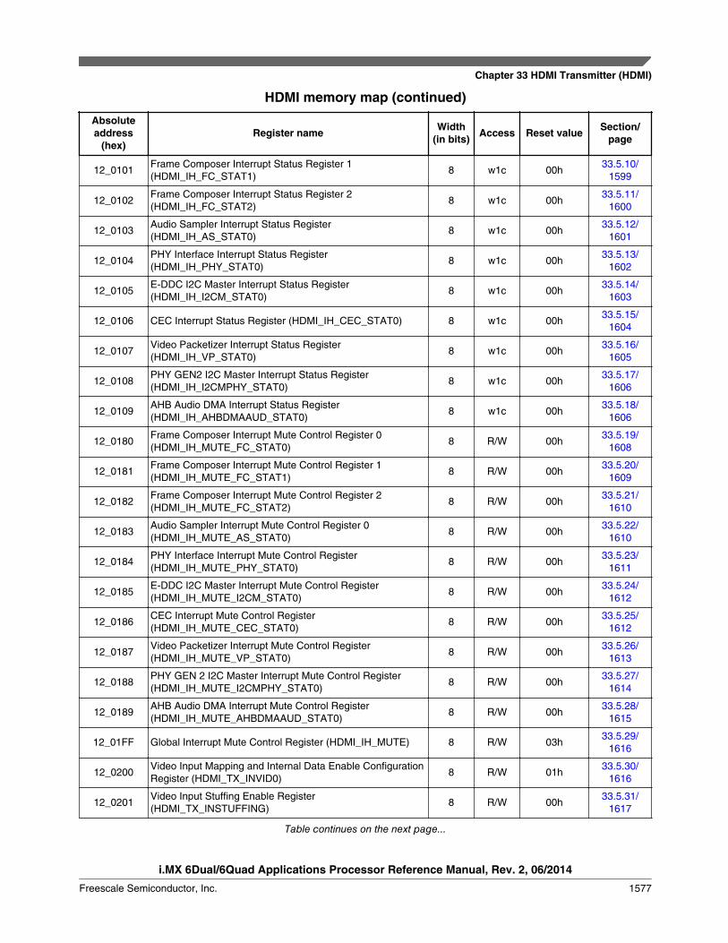
HDMI memory map (continued)
Absoluteaddress
(hex)Register name Width
(in bits) Access Reset value Section/page
12_0101Frame Composer Interrupt Status Register 1(HDMI_IH_FC_STAT1)
8 w1c 00h33.5.10/
1599
12_0102Frame Composer Interrupt Status Register 2(HDMI_IH_FC_STAT2)
8 w1c 00h33.5.11/
1600
12_0103Audio Sampler Interrupt Status Register(HDMI_IH_AS_STAT0)
8 w1c 00h33.5.12/
1601
12_0104PHY Interface Interrupt Status Register(HDMI_IH_PHY_STAT0)
8 w1c 00h33.5.13/
1602
12_0105E-DDC I2C Master Interrupt Status Register(HDMI_IH_I2CM_STAT0)
8 w1c 00h33.5.14/
1603
12_0106 CEC Interrupt Status Register (HDMI_IH_CEC_STAT0) 8 w1c 00h33.5.15/
1604
12_0107Video Packetizer Interrupt Status Register(HDMI_IH_VP_STAT0)
8 w1c 00h33.5.16/
1605
12_0108PHY GEN2 I2C Master Interrupt Status Register(HDMI_IH_I2CMPHY_STAT0)
8 w1c 00h33.5.17/
1606
12_0109AHB Audio DMA Interrupt Status Register(HDMI_IH_AHBDMAAUD_STAT0)
8 w1c 00h33.5.18/
1606
12_0180Frame Composer Interrupt Mute Control Register 0(HDMI_IH_MUTE_FC_STAT0)
8 R/W 00h33.5.19/
1608
12_0181Frame Composer Interrupt Mute Control Register 1(HDMI_IH_MUTE_FC_STAT1)
8 R/W 00h33.5.20/
1609
12_0182Frame Composer Interrupt Mute Control Register 2(HDMI_IH_MUTE_FC_STAT2)
8 R/W 00h33.5.21/
1610
12_0183Audio Sampler Interrupt Mute Control Register 0(HDMI_IH_MUTE_AS_STAT0)
8 R/W 00h33.5.22/
1610
12_0184PHY Interface Interrupt Mute Control Register(HDMI_IH_MUTE_PHY_STAT0)
8 R/W 00h33.5.23/
1611
12_0185E-DDC I2C Master Interrupt Mute Control Register(HDMI_IH_MUTE_I2CM_STAT0)
8 R/W 00h33.5.24/
1612
12_0186CEC Interrupt Mute Control Register(HDMI_IH_MUTE_CEC_STAT0)
8 R/W 00h33.5.25/
1612
12_0187Video Packetizer Interrupt Mute Control Register(HDMI_IH_MUTE_VP_STAT0)
8 R/W 00h33.5.26/
1613
12_0188PHY GEN 2 I2C Master Interrupt Mute Control Register(HDMI_IH_MUTE_I2CMPHY_STAT0)
8 R/W 00h33.5.27/
1614
12_0189AHB Audio DMA Interrupt Mute Control Register(HDMI_IH_MUTE_AHBDMAAUD_STAT0)
8 R/W 00h33.5.28/
1615
12_01FF Global Interrupt Mute Control Register (HDMI_IH_MUTE) 8 R/W 03h33.5.29/
1616
12_0200Video Input Mapping and Internal Data Enable ConfigurationRegister (HDMI_TX_INVID0)
8 R/W 01h33.5.30/
1616
12_0201Video Input Stuffing Enable Register(HDMI_TX_INSTUFFING)
8 R/W 00h33.5.31/
1617
Table continues on the next page...
Chapter 33 HDMI Transmitter (HDMI)
i.MX 6Dual/6Quad Applications Processor Reference Manual, Rev. 2, 06/2014
Freescale Semiconductor, Inc. 1577
HDMI memory map (continued)
Absoluteaddress
(hex)Register name Width
(in bits) Access Reset value Section/page
12_0202Video Input GY Data Channel Stuffing Register 0(HDMI_TX_GYDATA0)
8 R/W 00h33.5.32/
1618
12_0203Video Input GY Data Channel Stuffing Register 1(HDMI_TX_GYDATA1)
8 R/W 00h33.5.33/
1619
12_0204Video Input RCR Data Channel Stuffing Register 0(HDMI_TX_RCRDATA0)
8 R/W 00h33.5.34/
1619
12_0205Video Input RCR Data Channel Stuffing Register 1(HDMI_TX_RCRDATA1)
8 R/W 00h33.5.35/
1620
12_0206Video Input RCB Data Channel Stuffing Register 0(HDMI_TX_BCBDATA0)
8 R/W 00h33.5.36/
1620
12_0207Video Input RCB Data Channel Stuffing Register 1(HDMI_TX_BCBDATA1)
8 R/W 00h33.5.37/
1621
12_0800Video Packetizer Packing Phase Status Register(HDMI_VP_STATUS)
8 R 00h33.5.38/
1621
12_0801Video Packetizer Pixel Repetition and Color Depth Register(HDMI_VP_PR_CD)
8 R/W 00h33.5.39/
1622
12_0802Video Packetizer Stuffing and Default Packing PhaseRegister (HDMI_VP_STUFF)
8 R/W 00h33.5.40/
1623
12_0803Video Packetizer YCC422 Remapping Register(HDMI_VP_REMAP)
8 R/W 00h33.5.41/
1624
12_0804Video Packetizer Output, Bypass, and Enable ConfigurationRegister (HDMI_VP_CONF)
8 R/W 46h33.5.42/
1625
12_0805 VP_STAT (HDMI_VP_STAT) 8 R 00h33.5.43/
1625
12_0806 VP_INT (HDMI_VP_INT) 8 R 00h33.5.44/
1626
12_0807Video Packetizer Interrupt Mask Register(HDMI_VP_MASK)
8 R/W 00h33.5.45/
1627
12_0808 VP_POL (HDMI_VP_POL) 8 R/W FFh33.5.46/
1628
12_1000Frame Composer Input Video Configuration and HDCPKeepout Register (HDMI_FC_INVIDCONF)
8 R/W 70h33.5.47/
1629
12_1001Frame Composer Input Video HActive Pixels Register 0(HDMI_FC_INHACTIV0)
8 R/W 00h33.5.48/
1630
12_1002Frame Composer Input Video HActive Pixels Register 1(HDMI_FC_INHACTIV1)
8 R/W 00h33.5.49/
1631
12_1003Frame Composer Input Video HBlank Pixels Register 0(HDMI_FC_INHBLANK0)
8 R/W 00h33.5.50/
1631
12_1004Frame Composer Input Video HBlank Pixels Register 1(HDMI_FC_INHBLANK1)
8 R/W 00h33.5.51/
1632
12_1005Frame Composer Input Video VActive Pixels Register 0(HDMI_FC_INVACTIV0)
8 R/W 00h33.5.52/
1633
12_1006Frame Composer Input Video VActive Pixels Register 1(HDMI_FC_INVACTIV1)
8 R/W 00h33.5.53/
1633
Table continues on the next page...
HDMI Memory Map/Register Definition
i.MX 6Dual/6Quad Applications Processor Reference Manual, Rev. 2, 06/2014
1578 Freescale Semiconductor, Inc.
HDMI memory map (continued)
Absoluteaddress
(hex)Register name Width
(in bits) Access Reset value Section/page
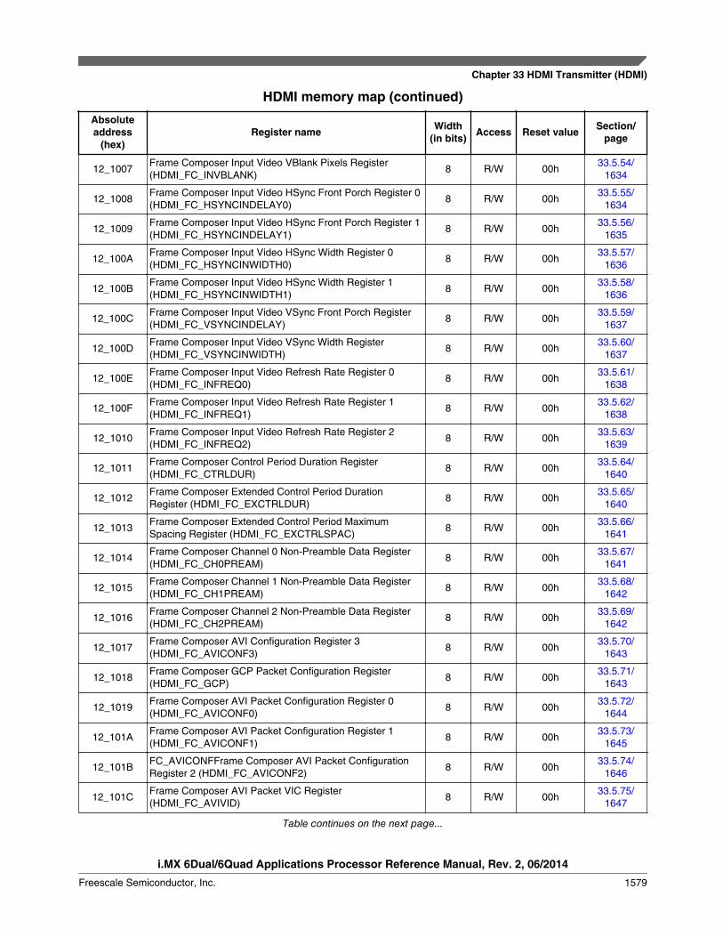
12_1007Frame Composer Input Video VBlank Pixels Register(HDMI_FC_INVBLANK)
8 R/W 00h33.5.54/
1634
12_1008Frame Composer Input Video HSync Front Porch Register 0(HDMI_FC_HSYNCINDELAY0)
8 R/W 00h33.5.55/
1634
12_1009Frame Composer Input Video HSync Front Porch Register 1(HDMI_FC_HSYNCINDELAY1)
8 R/W 00h33.5.56/
1635
12_100AFrame Composer Input Video HSync Width Register 0(HDMI_FC_HSYNCINWIDTH0)
8 R/W 00h33.5.57/
1636
12_100BFrame Composer Input Video HSync Width Register 1(HDMI_FC_HSYNCINWIDTH1)
8 R/W 00h33.5.58/
1636
12_100CFrame Composer Input Video VSync Front Porch Register(HDMI_FC_VSYNCINDELAY)
8 R/W 00h33.5.59/
1637
12_100DFrame Composer Input Video VSync Width Register(HDMI_FC_VSYNCINWIDTH)
8 R/W 00h33.5.60/
1637
12_100EFrame Composer Input Video Refresh Rate Register 0(HDMI_FC_INFREQ0)
8 R/W 00h33.5.61/
1638
12_100FFrame Composer Input Video Refresh Rate Register 1(HDMI_FC_INFREQ1)
8 R/W 00h33.5.62/
1638
12_1010Frame Composer Input Video Refresh Rate Register 2(HDMI_FC_INFREQ2)
8 R/W 00h33.5.63/
1639
12_1011Frame Composer Control Period Duration Register(HDMI_FC_CTRLDUR)
8 R/W 00h33.5.64/
1640
12_1012Frame Composer Extended Control Period DurationRegister (HDMI_FC_EXCTRLDUR)
8 R/W 00h33.5.65/
1640
12_1013Frame Composer Extended Control Period MaximumSpacing Register (HDMI_FC_EXCTRLSPAC)
8 R/W 00h33.5.66/
1641
12_1014Frame Composer Channel 0 Non-Preamble Data Register(HDMI_FC_CH0PREAM)
8 R/W 00h33.5.67/
1641
12_1015Frame Composer Channel 1 Non-Preamble Data Register(HDMI_FC_CH1PREAM)
8 R/W 00h33.5.68/
1642
12_1016Frame Composer Channel 2 Non-Preamble Data Register(HDMI_FC_CH2PREAM)
8 R/W 00h33.5.69/
1642
12_1017Frame Composer AVI Configuration Register 3(HDMI_FC_AVICONF3)
8 R/W 00h33.5.70/
1643
12_1018Frame Composer GCP Packet Configuration Register(HDMI_FC_GCP)
8 R/W 00h33.5.71/
1643
12_1019Frame Composer AVI Packet Configuration Register 0(HDMI_FC_AVICONF0)
8 R/W 00h33.5.72/
1644
12_101AFrame Composer AVI Packet Configuration Register 1(HDMI_FC_AVICONF1)
8 R/W 00h33.5.73/
1645
12_101BFC_AVICONFFrame Composer AVI Packet ConfigurationRegister 2 (HDMI_FC_AVICONF2)
8 R/W 00h33.5.74/
1646
12_101CFrame Composer AVI Packet VIC Register(HDMI_FC_AVIVID)
8 R/W 00h33.5.75/
1647
Table continues on the next page...
Chapter 33 HDMI Transmitter (HDMI)
i.MX 6Dual/6Quad Applications Processor Reference Manual, Rev. 2, 06/2014
Freescale Semiconductor, Inc. 1579

HDMI memory map (continued)
Absoluteaddress
(hex)Register name Width
(in bits) Access Reset value Section/page
12_101DFrame Composer AVI Packet End of Top Bar Register 0(HDMI_FC_AVIETB0)
8 R/W 00h33.5.76/
1647
12_101EFrame Composer AVI Packet End of Top Bar Register 1(HDMI_FC_AVIETB1)
8 R/W 00h33.5.77/
1648
12_101FFrame Composer AVI Packet Start of Bottom Bar Register 0(HDMI_FC_AVISBB0)
8 R/W 00h33.5.78/
1648
12_1020Frame Composer AVI Packet Start of Bottom Bar Register 1(HDMI_FC_AVISBB1)
8 R/W 00h33.5.79/
1649
12_1021Frame Composer AVI Packet End of Left Bar Register 0(HDMI_FC_AVIELB0)
8 R/W 00h33.5.80/
1649
12_1022Frame Composer AVI Packet End of Left Bar Register 1(HDMI_FC_AVIELB1)
8 R/W 00h33.5.81/
1650
12_1023Frame Composer AVI Packet Start of Right Bar Register 0(HDMI_FC_AVISRB0)
8 R/W 00h33.5.82/
1650
12_1024Frame Composer AVI Packet Start of Right Bar Register 1(HDMI_FC_AVISRB1)
8 R/W 00h33.5.83/
1651
12_1025Frame Composer AUD Packet Configuration Register 0(HDMI_FC_AUDICONF0)
8 R/W 00h33.5.84/
1651
12_1026Frame Composer AUD Packet Configuration Register 1(HDMI_FC_AUDICONF1)
8 R/W 00h33.5.85/
1652
12_1027Frame Composer AUD Packet Configuration Register 2(HDMI_FC_AUDICONF2)
8 R/W 00h33.5.86/
1652
12_1028Frame Composer AUD Packet Configuration Register 3(HDMI_FC_AUDICONF3)
8 R/W 00h33.5.87/
1653
12_1029Frame Composer VSI Packet Data IEEE Register 0(HDMI_FC_VSDIEEEID0)
8 R/W 00h33.5.88/
1653
12_102AFrame Composer VSI Packet Data Size Register(HDMI_FC_VSDSIZE)
8 R/W 1Bh33.5.89/
1654
12_1030Frame Composer VSI Packet Data IEEE Register 1(HDMI_FC_VSDIEEEID1)
8 R/W 00h33.5.90/
1654
12_1031Frame Composer VSI Packet Data IEEE Register 2(HDMI_FC_VSDIEEEID2)
8 R/W 00h33.5.91/
1655
12_1032Frame Composer VSI Packet Data IEEE Register 0(HDMI_FC_VSDPAYLOAD0)
8 R/W 00h33.5.92/
1655
12_1033Frame Composer VSI Packet Data IEEE Register 1(HDMI_FC_VSDPAYLOAD1)
8 R/W 00h33.5.93/
1656
12_1034Frame Composer VSI Packet Data IEEE Register 2(HDMI_FC_VSDPAYLOAD2)
8 R/W 00h33.5.94/
1656
12_1035Frame Composer VSI Packet Data IEEE Register 3(HDMI_FC_VSDPAYLOAD3)
8 R/W 00h33.5.95/
1657
12_1036Frame Composer VSI Packet Data IEEE Register 4(HDMI_FC_VSDPAYLOAD4)
8 R/W 00h33.5.96/
1657
12_1037Frame Composer VSI Packet Data IEEE Register 5(HDMI_FC_VSDPAYLOAD5)
8 R/W 00h33.5.97/
1658
Table continues on the next page...
HDMI Memory Map/Register Definition
i.MX 6Dual/6Quad Applications Processor Reference Manual, Rev. 2, 06/2014
1580 Freescale Semiconductor, Inc.
HDMI memory map (continued)
Absoluteaddress
(hex)Register name Width
(in bits) Access Reset value Section/page
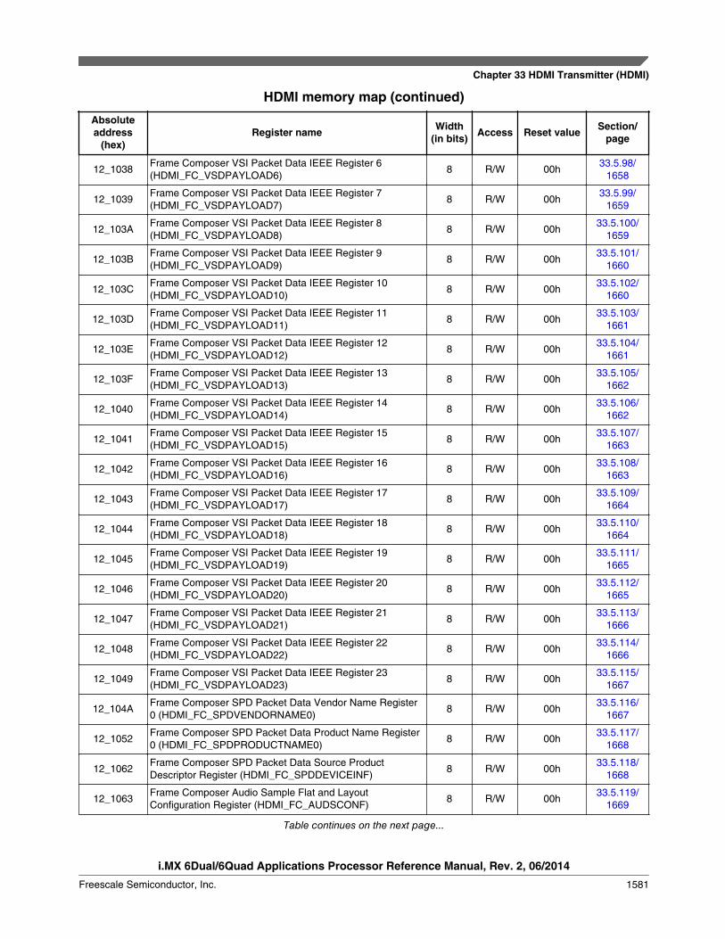
12_1038Frame Composer VSI Packet Data IEEE Register 6(HDMI_FC_VSDPAYLOAD6)
8 R/W 00h33.5.98/
1658
12_1039Frame Composer VSI Packet Data IEEE Register 7(HDMI_FC_VSDPAYLOAD7)
8 R/W 00h33.5.99/
1659
12_103AFrame Composer VSI Packet Data IEEE Register 8(HDMI_FC_VSDPAYLOAD8)
8 R/W 00h33.5.100/
1659
12_103BFrame Composer VSI Packet Data IEEE Register 9(HDMI_FC_VSDPAYLOAD9)
8 R/W 00h33.5.101/
1660
12_103CFrame Composer VSI Packet Data IEEE Register 10(HDMI_FC_VSDPAYLOAD10)
8 R/W 00h33.5.102/
1660
12_103DFrame Composer VSI Packet Data IEEE Register 11(HDMI_FC_VSDPAYLOAD11)
8 R/W 00h33.5.103/
1661
12_103EFrame Composer VSI Packet Data IEEE Register 12(HDMI_FC_VSDPAYLOAD12)
8 R/W 00h33.5.104/
1661
12_103FFrame Composer VSI Packet Data IEEE Register 13(HDMI_FC_VSDPAYLOAD13)
8 R/W 00h33.5.105/
1662
12_1040Frame Composer VSI Packet Data IEEE Register 14(HDMI_FC_VSDPAYLOAD14)
8 R/W 00h33.5.106/
1662
12_1041Frame Composer VSI Packet Data IEEE Register 15(HDMI_FC_VSDPAYLOAD15)
8 R/W 00h33.5.107/
1663
12_1042Frame Composer VSI Packet Data IEEE Register 16(HDMI_FC_VSDPAYLOAD16)
8 R/W 00h33.5.108/
1663
12_1043Frame Composer VSI Packet Data IEEE Register 17(HDMI_FC_VSDPAYLOAD17)
8 R/W 00h33.5.109/
1664
12_1044Frame Composer VSI Packet Data IEEE Register 18(HDMI_FC_VSDPAYLOAD18)
8 R/W 00h33.5.110/
1664
12_1045Frame Composer VSI Packet Data IEEE Register 19(HDMI_FC_VSDPAYLOAD19)
8 R/W 00h33.5.111/
1665
12_1046Frame Composer VSI Packet Data IEEE Register 20(HDMI_FC_VSDPAYLOAD20)
8 R/W 00h33.5.112/
1665
12_1047Frame Composer VSI Packet Data IEEE Register 21(HDMI_FC_VSDPAYLOAD21)
8 R/W 00h33.5.113/
1666
12_1048Frame Composer VSI Packet Data IEEE Register 22(HDMI_FC_VSDPAYLOAD22)
8 R/W 00h33.5.114/
1666
12_1049Frame Composer VSI Packet Data IEEE Register 23(HDMI_FC_VSDPAYLOAD23)
8 R/W 00h33.5.115/
1667
12_104AFrame Composer SPD Packet Data Vendor Name Register0 (HDMI_FC_SPDVENDORNAME0)
8 R/W 00h33.5.116/
1667
12_1052Frame Composer SPD Packet Data Product Name Register0 (HDMI_FC_SPDPRODUCTNAME0)
8 R/W 00h33.5.117/
1668
12_1062Frame Composer SPD Packet Data Source ProductDescriptor Register (HDMI_FC_SPDDEVICEINF)
8 R/W 00h33.5.118/
1668
12_1063Frame Composer Audio Sample Flat and LayoutConfiguration Register (HDMI_FC_AUDSCONF)
8 R/W 00h33.5.119/
1669
Table continues on the next page...
Chapter 33 HDMI Transmitter (HDMI)
i.MX 6Dual/6Quad Applications Processor Reference Manual, Rev. 2, 06/2014
Freescale Semiconductor, Inc. 1581
HDMI memory map (continued)
Absoluteaddress
(hex)Register name Width
(in bits) Access Reset value Section/page
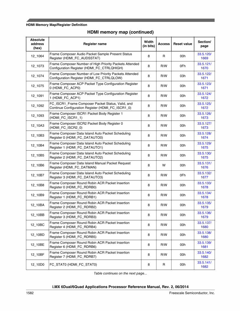
12_1064Frame Composer Audio Packet Sample Present StatusRegister (HDMI_FC_AUDSSTAT)
8 R 00h33.5.120/
1669
12_1073Frame Composer Number of High Priority Packets AttendedConfiguration Register (HDMI_FC_CTRLQHIGH)
8 R/W 0Fh33.5.121/
1670
12_1074Frame Composer Number of Low Priority Packets AttendedConfiguration Register (HDMI_FC_CTRLQLOW)
8 R/W 03h33.5.122/
1671
12_1075Frame Composer ACP Packet Type Configuration Register0 (HDMI_FC_ACP0)
8 R/W 00h33.5.123/
1671
12_1091Frame Composer ACP Packet Type Configuration Register1 (HDMI_FC_ACP1)
8 R/W 00h33.5.124/
1672
12_1092FC_ISCR1_Frame Composer Packet Status, Valid, andContinue Configuration Register (HDMI_FC_ISCR1_0)
8 R/W 00h33.5.125/
1672
12_1093Frame Composer ISCR1 Packet Body Register 1(HDMI_FC_ISCR1_1)
8 R/W 00h33.5.126/
1673
12_10A3Frame Composer ISCR2 Packet Body Register 0(HDMI_FC_ISCR2_0)
8 R/W 00h33.5.127/
1673
12_10B3Frame Composer Data Island Auto Packet SchedulingRegister 0 (HDMI_FC_DATAUTO0)
8 R/W 00h33.5.128/
1674
12_10B4Frame Composer Data Island Auto Packet SchedulingRegister 1 (HDMI_FC_DATAUTO1)
8 R/W 00h33.5.129/
1675
12_10B5Frame Composer Data Island Auto Packet SchedulingRegister 2 (HDMI_FC_DATAUTO2)
8 R/W 00h33.5.130/
1675
12_10B6Frame Composer Data Island Manual Packet RequestRegister (HDMI_FC_DATMAN)
8 W 00h33.5.131/
1676
12_10B7Frame Composer Data Island Auto Packet SchedulingRegister 3 (HDMI_FC_DATAUTO3)
8 R/W 0Fh33.5.132/
1677
12_10B8Frame Composer Round Robin ACR Packet InsertionRegister 0 (HDMI_FC_RDRB0)
8 R/W 00h33.5.133/
1678
12_10B9Frame Composer Round Robin ACR Packet InsertionRegister 1 (HDMI_FC_RDRB1)
8 R/W 00h33.5.134/
1678
12_10BAFrame Composer Round Robin ACR Packet InsertionRegister 2 (HDMI_FC_RDRB2)
8 R/W 00h33.5.135/
1679
12_10BBFrame Composer Round Robin ACR Packet InsertionRegister 3 (HDMI_FC_RDRB3)
8 R/W 00h33.5.136/
1679
12_10BCFrame Composer Round Robin ACR Packet InsertionRegister 4 (HDMI_FC_RDRB4)
8 R/W 00h33.5.137/
1680
12_10BDFrame Composer Round Robin ACR Packet InsertionRegister 5 (HDMI_FC_RDRB5)
8 R/W 00h33.5.138/
1680
12_10BEFrame Composer Round Robin ACR Packet InsertionRegister 6 (HDMI_FC_RDRB6)
8 R/W 00h33.5.139/
1681
12_10BFFrame Composer Round Robin ACR Packet InsertionRegister 7 (HDMI_FC_RDRB7)
8 R/W 00h33.5.140/
1682
12_10D0 FC_STAT0 (HDMI_FC_STAT0) 8 R 00h33.5.141/
1682
Table continues on the next page...
HDMI Memory Map/Register Definition
i.MX 6Dual/6Quad Applications Processor Reference Manual, Rev. 2, 06/2014
1582 Freescale Semiconductor, Inc.

HDMI memory map (continued)
Absoluteaddress
(hex)Register name Width
(in bits) Access Reset value Section/page
12_10D1 FC_INT0 (HDMI_FC_INT0) 8 R/W 00h33.5.142/
1683
12_10D2Frame Composer Packet Interrupt Mask Register 0(HDMI_FC_MASK0)
8 R/W 25h33.5.143/
1684
12_10D3 FC_POL0 (HDMI_FC_POL0) 8 R/W FFh33.5.144/
1685
12_10D4 FC_STAT1 (HDMI_FC_STAT1) 8 R/W 00h33.5.145/
1686
12_10D5 FC_INT1 (HDMI_FC_INT1) 8 R/W 00h33.5.146/
1686
12_10D6Frame Composer Packet Interrupt Mask Register 1(HDMI_FC_MASK1)
8 R/W 00h33.5.147/
1687
12_10D7 FC_POL1 (HDMI_FC_POL1) 8 R/W FFh33.5.148/
1688
12_10D8 FC_STAT2 (HDMI_FC_STAT2) 8 R/W 00h33.5.149/
1689
12_10D9 FC_INT2 (HDMI_FC_INT2) 8 R/W 00h33.5.150/
1690
12_10DAFrame Composer High/Low Priority Overflow Interrupt MaskRegister 2 (HDMI_FC_MASK2)
8 R/W 00h33.5.151/
1690
12_10DB FC_POL2 (HDMI_FC_POL2) 8 R/W 03h33.5.152/
1691
12_10E0Frame Composer Pixel Repetition Configuration Register(HDMI_FC_PRCONF)
8 R/W 10h33.5.153/
1692
12_1100Frame Composer GMD Packet Status Register(HDMI_FC_GMD_STAT)
8 R 00h33.5.154/
1693
12_1101Frame Composer GMD Packet Enable Register(HDMI_FC_GMD_EN)
8 R/W 00h33.5.155/
1694
12_1102Frame Composer GMD Packet Update Register(HDMI_FC_GMD_UP)
8 W 00h33.5.156/
1694
12_1103Frame Composer GMD Packet Schedule ConfigurationRegister (HDMI_FC_GMD_CONF)
8 R/W 10h33.5.157/
1695
12_1104Frame Composer GMD Packet Profile and Gamut SequenceConfiguration Register (HDMI_FC_GMD_HB)
8 R/W 00h33.5.158/
1696
12_1105Frame Composer GMD Packet Body Register 0(HDMI_FC_GMD_PB0)
8 R/W 00h33.5.159/
1696
12_1106Frame Composer GMD Packet Body Register 1(HDMI_FC_GMD_PB1)
8 R/W 00h33.5.160/
1697
12_1107Frame Composer GMD Packet Body Register 2(HDMI_FC_GMD_PB2)
8 R/W 00h33.5.161/
1697
12_1108Frame Composer GMD Packet Body Register 3(HDMI_FC_GMD_PB3)
8 R/W 00h33.5.162/
1698
12_1109Frame Composer GMD Packet Body Register 4(HDMI_FC_GMD_PB4)
8 R/W 00h33.5.163/
1698
Table continues on the next page...
Chapter 33 HDMI Transmitter (HDMI)
i.MX 6Dual/6Quad Applications Processor Reference Manual, Rev. 2, 06/2014
Freescale Semiconductor, Inc. 1583
HDMI memory map (continued)
Absoluteaddress
(hex)Register name Width
(in bits) Access Reset value Section/page
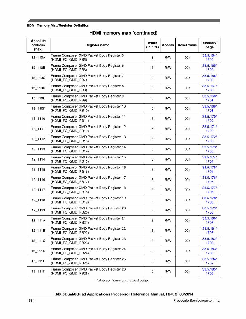
12_110AFrame Composer GMD Packet Body Register 5(HDMI_FC_GMD_PB5)
8 R/W 00h33.5.164/
1699
12_110BFrame Composer GMD Packet Body Register 6(HDMI_FC_GMD_PB6)
8 R/W 00h33.5.165/
1699
12_110CFrame Composer GMD Packet Body Register 7(HDMI_FC_GMD_PB7)
8 R/W 00h33.5.166/
1700
12_110DFrame Composer GMD Packet Body Register 8(HDMI_FC_GMD_PB8)
8 R/W 00h33.5.167/
1700
12_110EFrame Composer GMD Packet Body Register 9(HDMI_FC_GMD_PB9)
8 R/W 00h33.5.168/
1701
12_110FFrame Composer GMD Packet Body Register 10(HDMI_FC_GMD_PB10)
8 R/W 00h33.5.169/
1701
12_1110Frame Composer GMD Packet Body Register 11(HDMI_FC_GMD_PB11)
8 R/W 00h33.5.170/
1702
12_1111Frame Composer GMD Packet Body Register 12(HDMI_FC_GMD_PB12)
8 R/W 00h33.5.171/
1702
12_1112Frame Composer GMD Packet Body Register 13(HDMI_FC_GMD_PB13)
8 R/W 00h33.5.172/
1703
12_1113Frame Composer GMD Packet Body Register 14(HDMI_FC_GMD_PB14)
8 R/W 00h33.5.173/
1703
12_1114Frame Composer GMD Packet Body Register 15(HDMI_FC_GMD_PB15)
8 R/W 00h33.5.174/
1704
12_1115Frame Composer GMD Packet Body Register 16(HDMI_FC_GMD_PB16)
8 R/W 00h33.5.175/
1704
12_1116Frame Composer GMD Packet Body Register 17(HDMI_FC_GMD_PB17)
8 R/W 00h33.5.176/
1705
12_1117Frame Composer GMD Packet Body Register 18(HDMI_FC_GMD_PB18)
8 R/W 00h33.5.177/
1705
12_1118Frame Composer GMD Packet Body Register 19(HDMI_FC_GMD_PB19)
8 R/W 00h33.5.178/
1706
12_1119Frame Composer GMD Packet Body Register 20(HDMI_FC_GMD_PB20)
8 R/W 00h33.5.179/
1706
12_111AFrame Composer GMD Packet Body Register 21(HDMI_FC_GMD_PB21)
8 R/W 00h33.5.180/
1707
12_111BFrame Composer GMD Packet Body Register 22(HDMI_FC_GMD_PB22)
8 R/W 00h33.5.181/
1707
12_111CFrame Composer GMD Packet Body Register 23(HDMI_FC_GMD_PB23)
8 R/W 00h33.5.182/
1708
12_111DFrame Composer GMD Packet Body Register 24(HDMI_FC_GMD_PB24)
8 R/W 00h33.5.183/
1708
12_111EFrame Composer GMD Packet Body Register 25(HDMI_FC_GMD_PB25)
8 R/W 00h33.5.184/
1709
12_111FFrame Composer GMD Packet Body Register 26(HDMI_FC_GMD_PB26)
8 R/W 00h33.5.185/
1709
Table continues on the next page...
HDMI Memory Map/Register Definition
i.MX 6Dual/6Quad Applications Processor Reference Manual, Rev. 2, 06/2014
1584 Freescale Semiconductor, Inc.

HDMI memory map (continued)
Absoluteaddress
(hex)Register name Width
(in bits) Access Reset value Section/page
12_1120Frame Composer GMD Packet Body Register 27(HDMI_FC_GMD_PB27)
8 R/W 00h33.5.186/
1710
12_1200Frame Composer Video/Audio Force Enable Register(HDMI_FC_DBGFORCE)
8 R/W 00h33.5.187/
1710
12_1201Frame Composer Audio Channel 0 Register 0(HDMI_FC_DBGAUD0CH0)
8 R/W 00h33.5.188/
1711
12_1202Frame Composer Audio Channel 0 Register 1(HDMI_FC_DBGAUD1CH0)
8 R/W 00h33.5.189/
1712
12_1203Frame Composer Audio Channel 0 Register 2(HDMI_FC_DBGAUD2CH0)
8 R/W 00h33.5.190/
1712
12_1204Frame Composer Audio Channel 1 Register 0(HDMI_FC_DBGAUD0CH1)
8 R/W 00h33.5.191/
1713
12_1205Frame Composer Audio Channel 1 Register 1(HDMI_FC_DBGAUD1CH1)
8 R/W 00h33.5.192/
1713
12_1206Frame Composer Audio Channel 1 Register 2(HDMI_FC_DBGAUD2CH1)
8 R/W 00h33.5.193/
1714
12_1207Frame Composer Debug Audio Channel 2 Register 0(HDMI_FC_DBGAUD0CH2)
8 R/W 00h33.5.194/
1714
12_1208Frame Composer Debug Audio Channel 2 Register 1(HDMI_FC_DBGAUD1CH2)
8 R/W 00h33.5.195/
1715
12_1209Frame Composer Audio Channel 2 Register 2(HDMI_FC_DBGAUD2CH2)
8 R/W 00h33.5.196/
1715
12_120AFrame Composer Audio Channel 3 Register 0(HDMI_FC_DBGAUD0CH3)
8 R/W 00h33.5.197/
1716
12_120BFrame Composer Audio Channel 3 Register 1(HDMI_FC_DBGAUD1CH3)
8 R/W 00h33.5.198/
1716
12_120CFrame Composer Audio Channel 3 Register 2(HDMI_FC_DBGAUD2CH3)
8 R/W 00h33.5.199/
1717
12_120DFrame Composer Audio Channel 4 Register 0(HDMI_FC_DBGAUD0CH4)
8 R/W 00h33.5.200/
1717
12_120EFrame Composer Audio Channel 4 Register 1(HDMI_FC_DBGAUD1CH4)
8 R/W 00h33.5.201/
1718
12_120FFrame Composer Audio Channel 4 Register 2(HDMI_FC_DBGAUD2CH4)
8 R/W 00h33.5.202/
1718
12_1210Frame Composer Audio Channel 5 Register 0(HDMI_FC_DBGAUD0CH5)
8 R/W 00h33.5.203/
1719
12_1211Frame Composer Audio Channel 5 Register 1(HDMI_FC_DBGAUD1CH5)
8 R/W 00h33.5.204/
1719
12_1212Frame Composer Audio Channel 5 Register 2(HDMI_FC_DBGAUD2CH5)
8 R/W 00h33.5.205/
1720
12_1213Frame Composer Audio Channel 6 Register 0(HDMI_FC_DBGAUD0CH6)
8 R/W 00h33.5.206/
1720
12_1214Frame Composer Audio Channel 6 Register 1(HDMI_FC_DBGAUD1CH6)
8 R/W 00h33.5.207/
1721
Table continues on the next page...
Chapter 33 HDMI Transmitter (HDMI)
i.MX 6Dual/6Quad Applications Processor Reference Manual, Rev. 2, 06/2014
Freescale Semiconductor, Inc. 1585
HDMI memory map (continued)
Absoluteaddress
(hex)Register name Width
(in bits) Access Reset value Section/page
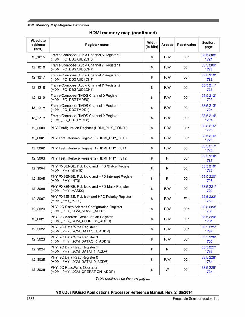
12_1215Frame Composer Audio Channel 6 Register 2(HDMI_FC_DBGAUD2CH6)
8 R/W 00h33.5.208/
1721
12_1216Frame Composer Audio Channel 7 Register 1(HDMI_FC_DBGAUD0CH7)
8 R/W 00h33.5.209/
1722
12_1217Frame Composer Audio Channel 7 Register 0(HDMI_FC_DBGAUD1CH7)
8 R/W 00h33.5.210/
1722
12_1218Frame Composer Audio Channel 7 Register 2(HDMI_FC_DBGAUD2CH7)
8 R/W 00h33.5.211/
1723
12_1219Frame Composer TMDS Channel 0 Register(HDMI_FC_DBGTMDS0)
8 R/W 00h33.5.212/
1723
12_121AFrame Composer TMDS Channel 1 Register(HDMI_FC_DBGTMDS1)
8 R/W 00h33.5.213/
1724
12_121BFrame Composer TMDS Channel 2 Register(HDMI_FC_DBGTMDS2)
8 R/W 00h33.5.214/
1724
12_3000 PHY Configuration Register (HDMI_PHY_CONF0) 8 R/W 06h33.5.215/
1725
12_3001 PHY Test Interface Register 0 (HDMI_PHY_TST0) 8 R/W 00h33.5.216/
1726
12_3002 PHY Test Interface Register 1 (HDMI_PHY_TST1) 8 R/W 00h33.5.217/
1726
12_3003 PHY Test Interface Register 2 (HDMI_PHY_TST2) 8 R 00h33.5.218/
1727
12_3004PHY RXSENSE, PLL lock, and HPD Status Register(HDMI_PHY_STAT0)
8 R 00h33.5.219/
1727
12_3005PHY RXSENSE, PLL lock, and HPD Interrupt Register(HDMI_PHY_INT0)
8 R 00h33.5.220/
1728
12_3006PHY RXSENSE, PLL lock, and HPD Mask Register(HDMI_PHY_MASK0)
8 R/W 00h33.5.221/
1729
12_3007PHY RXSENSE, PLL lock and HPD Polarity Register(HDMI_PHY_POL0)
8 R/W F3h33.5.222/
1730
12_3020PHY I2C Slave Address Configuration Register(HDMI_PHY_I2CM_SLAVE_ADDR)
8 R/W 00h33.5.223/
1731
12_3021PHY I2C Address Configuration Register(HDMI_PHY_I2CM_ADDRESS_ADDR)
8 R/W 00h33.5.224/
1731
12_3022PHY I2C Data Write Register 1(HDMI_PHY_I2CM_DATAO_1_ADDR)
8 R/W 00h33.5.225/
1732
12_3023PHY I2C Data Write Register 0(HDMI_PHY_I2CM_DATAO_0_ADDR)
8 R/W 00h33.5.226/
1733
12_3024PHY I2C Data Read Register 1(HDMI_PHY_I2CM_DATAI_1_ADDR)
8 R 00h33.5.227/
1733
12_3025PHY I2C Data Read Register 0(HDMI_PHY_I2CM_DATAI_0_ADDR)
8 R/W 00h33.5.228/
1734
12_3026PHY I2C Read/Write Operation(HDMI_PHY_I2CM_OPERATION_ADDR)
8 W 00h33.5.229/
1734
Table continues on the next page...
HDMI Memory Map/Register Definition
i.MX 6Dual/6Quad Applications Processor Reference Manual, Rev. 2, 06/2014
1586 Freescale Semiconductor, Inc.

HDMI memory map (continued)
Absoluteaddress
(hex)Register name Width
(in bits) Access Reset value Section/page
12_3027PHY I2C Done Interrupt Register(HDMI_PHY_I2CM_INT_ADDR)
8 R/W 08h33.5.230/
1735
12_3028PHY I2C Done Interrupt Register(HDMI_PHY_I2CM_CTLINT_ADDR)
8 R/W 88h33.5.231/
1736
12_3029PHY I2C Speed Control Register(HDMI_PHY_I2CM_DIV_ADDR)
8 R/W 0Bh33.5.232/
1737
12_302APHY I2C Software Reset Register(HDMI_PHY_I2CM_SOFTRSTZ_ADDR)
8 R/W 01h33.5.233/
1737
12_302BPHY I2C Slow Speed SCL High Level Control Register 1(HDMI_PHY_I2CM_SS_SCL_HCNT_1_ADDR)
8 R/W 00h33.5.234/
1738
12_302CPHY I2C Slow Speed SCL High Level Control Register 0(HDMI_PHY_I2CM_SS_SCL_HCNT_0_ADDR)
8 R/W 6Ch33.5.235/
1739
12_302DPHY I2C Slow Speed SCL Low Level Control Register 1(HDMI_PHY_I2CM_SS_SCL_LCNT_1_ADDR)
8 R/W 00h33.5.236/
1739
12_302EPHY I2C Slow Speed SCL Low Level Control Register 0(HDMI_PHY_I2CM_SS_SCL_LCNT_0_ADDR)
8 R/W 7Fh33.5.237/
1740
12_302FPHY I2C Fast Speed SCL High Level Control Register 1(HDMI_PHY_I2CM_FS_SCL_HCNT_1_ADDR)
8 R/W 00h33.5.238/
1740
12_3030PHY I2C Fast Speed SCL High Level Control Register 0(HDMI_PHY_I2CM_FS_SCL_HCNT_0_ADDR)
8 R/W 11h33.5.239/
1741
12_3031PHY I2C Fast Speed SCL Low Level Control Register 1(HDMI_PHY_I2CM_FS_SCL_LCNT_1_ADDR)
8 R/W 00h33.5.240/
1741
12_3032PHY I2C Fast Speed SCL Low Level Control Register 0(HDMI_PHY_I2CM_FS_SCL_LCNT_0_ADDR)
8 R/W 24h33.5.241/
1742
12_3200Audio Clock Regenerator N Value Register 1(HDMI_AUD_N1)
8 R/W 00h33.5.242/
1742
12_3201Audio Clock Regenerator N Value Register 2(HDMI_AUD_N2)
8 R/W 00h33.5.243/
1743
12_3202Audio Clock Regenerator N Value Register 3(HDMI_AUD_N3)
8 R/W 00h33.5.244/
1743
12_3203 AUD_CTS1 (HDMI_AUD_CTS1) 8 R/W 00h33.5.245/
1744
12_3204 AUD_CTS2 (HDMI_AUD_CTS2) 8 R/W 00h33.5.246/
1744
12_3205 AUD_CTS3 (HDMI_AUD_CTS3) 8 R/W 00h33.5.247/
1745
12_3600 Audio DMA Start Register (HDMI_AHB_DMA_CONF0) 8 R/W 00h33.5.248/
1745
12_3601 AHB_DMA_START (HDMI_AHB_DMA_START) 8 R/W 00h33.5.249/
1746
12_3602 Audio DMA Stop Register (HDMI_AHB_DMA_STOP) 8 R/W 00h33.5.250/
1747
12_3603Audio DMA FIFO Threshold Register(HDMI_AHB_DMA_THRSLD)
8 R/W 00h33.5.251/
1748
Table continues on the next page...
Chapter 33 HDMI Transmitter (HDMI)
i.MX 6Dual/6Quad Applications Processor Reference Manual, Rev. 2, 06/2014
Freescale Semiconductor, Inc. 1587

HDMI memory map (continued)
Absoluteaddress
(hex)Register name Width
(in bits) Access Reset value Section/page
12_3604Audio DMA Start Address Register 0(HDMI_AHB_DMA_STRADDR0)
8 R/W 00h33.5.252/
1748
12_3605Audio DMA Start Address Register 1(HDMI_AHB_DMA_STRADDR1)
8 R/W 00h33.5.253/
1749
12_3606Audio DMA Start Address Register 2(HDMI_AHB_DMA_STRADDR2)
8 R/W 00h33.5.254/
1749
12_3607Audio DMA Start Address Register 3(HDMI_AHB_DMA_STRADDR3)
8 R/W 00h33.5.255/
1750
12_3608Audio DMA Stop Address Register 0(HDMI_AHB_DMA_STPADDR0)
8 R/W 00h33.5.256/
1750
12_3609Audio DMA Stop Address Register 1(HDMI_AHB_DMA_STPADDR1)
8 R/W 00h33.5.257/
1751
12_360AAudio DMA Stop Address Register 2(HDMI_AHB_DMA_STPADDR2)
8 R/W 00h33.5.258/
1751
12_360BAudio DMA Stop Address Register 3(HDMI_AHB_DMA_STPADDR3)
8 R/W 00h33.5.259/
1752
12_360CAudio DMA Burst Start Address Register 0(HDMI_AHB_DMA_BSTADDR0)
8 R 00h33.5.260/
1752
12_360DAudio DMA Burst Start Address Register 1(HDMI_AHB_DMA_BSTADDR1)
8 R 00h33.5.261/
1753
12_360EAudio DMA Burst Start Address Register 2(HDMI_AHB_DMA_BSTADDR2)
8 R 00h33.5.262/
1753
12_360FAudio DMA Burst Start Address Register 3(HDMI_AHB_DMA_BSTADDR3)
8 R 00h33.5.263/
1753
12_3610Audio DMA Burst Length Register 0(HDMI_AHB_DMA_MBLENGTH0)
8 R 00h33.5.264/
1754
12_3611Audio DMA Burst Length Register 1(HDMI_AHB_DMA_MBLENGTH1)
8 R 00h33.5.265/
1755
12_3612Audio DMA Interrupt Status Register(HDMI_AHB_DMA_STAT)
8 R 00h33.5.266/
1755
12_3613 Audio DMA Interrupt Register (HDMI_AHB_DMA_INT) 8 R 00h33.5.267/
1756
12_3614Audio DMA Mask Interrupt Register(HDMI_AHB_DMA_MASK)
8 R/W 00h33.5.268/
1757
12_3615Audio DMA Polarity Interrupt Register(HDMI_AHB_DMA_POL)
8 R/W 00h33.5.269/
1758
12_3616Audio DMA Channel Enable Configuration Register 1(HDMI_AHB_DMA_CONF1)
8 R/W 00h33.5.270/
1759
12_3617Audio DMA Buffer Interrupt Status Register(HDMI_AHB_DMA_BUFFSTAT)
8 R 00h33.5.271/
1760
12_3618Audio DMA Buffer Interrupt Register(HDMI_AHB_DMA_BUFFINT)
8 R 00h33.5.272/
1761
12_3619Audio DMA Buffer Mask Interrupt Register(HDMI_AHB_DMA_BUFFMASK)
8 R/W 00h33.5.273/
1762
Table continues on the next page...
HDMI Memory Map/Register Definition
i.MX 6Dual/6Quad Applications Processor Reference Manual, Rev. 2, 06/2014
1588 Freescale Semiconductor, Inc.
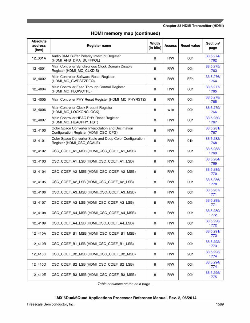
HDMI memory map (continued)
Absoluteaddress
(hex)Register name Width
(in bits) Access Reset value Section/page
12_361AAudio DMA Buffer Polarity Interrupt Register(HDMI_AHB_DMA_BUFFPOL)
8 R/W 00h33.5.274/
1762
12_4001Main Controller Synchronous Clock Domain DisableRegister (HDMI_MC_CLKDIS)
8 R/W 00h33.5.275/
1763
12_4002Main Controller Software Reset Register(HDMI_MC_SWRSTZREQ)
8 R/W FFh33.5.276/
1764
12_4004Main Controller Feed Through Control Register(HDMI_MC_FLOWCTRL)
8 R/W 00h33.5.277/
1765
12_4005 Main Controller PHY Reset Register (HDMI_MC_PHYRSTZ) 8 R/W 00h33.5.278/
1765
12_4006Main Controller Clock Present Register(HDMI_MC_LOCKONCLOCK)
8 w1c 00h33.5.279/
1766
12_4007Main Controller HEAC PHY Reset Register(HDMI_MC_HEACPHY_RST)
8 R/W 00h33.5.280/
1767
12_4100Color Space Converter Interpolation and DecimationConfiguration Register (HDMI_CSC_CFG)
8 R/W 00h33.5.281/
1767
12_4101Color Space Converter Scale and Deep Color ConfigurationRegister (HDMI_CSC_SCALE)
8 R/W 01h33.5.282/
1768
12_4102 CSC_COEF_A1_MSB (HDMI_CSC_COEF_A1_MSB) 8 R/W 20h33.5.283/
1769
12_4103 CSC_COEF_A1_LSB (HDMI_CSC_COEF_A1_LSB) 8 R/W 00h33.5.284/
1769
12_4104 CSC_COEF_A2_MSB (HDMI_CSC_COEF_A2_MSB) 8 R/W 00h33.5.285/
1770
12_4105 CSC_COEF_A2_LSB (HDMI_CSC_COEF_A2_LSB) 8 R/W 00h33.5.286/
1770
12_4106 CSC_COEF_A3_MSB (HDMI_CSC_COEF_A3_MSB) 8 R/W 00h33.5.287/
1771
12_4107 CSC_COEF_A3_LSB (HDMI_CSC_COEF_A3_LSB) 8 R/W 00h33.5.288/
1771
12_4108 CSC_COEF_A4_MSB (HDMI_CSC_COEF_A4_MSB) 8 R/W 00h33.5.289/
1772
12_4109 CSC_COEF_A4_LSB (HDMI_CSC_COEF_A4_LSB) 8 R/W 00h33.5.290/
1772
12_410A CSC_COEF_B1_MSB (HDMI_CSC_COEF_B1_MSB) 8 R/W 00h33.5.291/
1773
12_410B CSC_COEF_B1_LSB (HDMI_CSC_COEF_B1_LSB) 8 R/W 00h33.5.292/
1773
12_410C CSC_COEF_B2_MSB (HDMI_CSC_COEF_B2_MSB) 8 R/W 20h33.5.293/
1774
12_410D CSC_COEF_B2_LSB (HDMI_CSC_COEF_B2_LSB) 8 R/W 00h33.5.294/
1774
12_410E CSC_COEF_B3_MSB (HDMI_CSC_COEF_B3_MSB) 8 R/W 00h33.5.295/
1775
Table continues on the next page...
Chapter 33 HDMI Transmitter (HDMI)
i.MX 6Dual/6Quad Applications Processor Reference Manual, Rev. 2, 06/2014
Freescale Semiconductor, Inc. 1589

HDMI memory map (continued)
Absoluteaddress
(hex)Register name Width
(in bits) Access Reset value Section/page
12_410F CSC_COEF_B3_LSB (HDMI_CSC_COEF_B3_LSB) 8 R/W 00h33.5.296/
1775
12_4110 CSC_COEF_B4_MSB (HDMI_CSC_COEF_B4_MSB) 8 R/W 00h33.5.297/
1776
12_4111 CSC_COEF_B4_LSB (HDMI_CSC_COEF_B4_LSB) 8 R/W 00h33.5.298/
1776
12_4112 CSC_COEF_C1_MSB (HDMI_CSC_COEF_C1_MSB) 8 R/W 00h33.5.299/
1777
12_4113 CSC_COEF_C1_LSB (HDMI_CSC_COEF_C1_LSB) 8 R/W 00h33.5.300/
1777
12_4114 CSC_COEF_C2_MSB (HDMI_CSC_COEF_C2_MSB) 8 R/W 00h33.5.301/
1778
12_4115 CSC_COEF_C2_LSB (HDMI_CSC_COEF_C2_LSB) 8 R/W 00h33.5.302/
1778
12_4116 CSC_COEF_C3_MSB (HDMI_CSC_COEF_C3_MSB) 8 R/W 20h33.5.303/
1779
12_4117 CSC_COEF_C3_LSB (HDMI_CSC_COEF_C3_LSB) 8 R/W 00h33.5.304/
1779
12_4118 CSC_COEFC4_MSB (HDMI_CSC_COEFC4_MSB) 8 R/W 00h33.5.305/
1780
12_4119 CSC_COEFC4_LSB (HDMI_CSC_COEFC4_LSB) 8 R/W 00h33.5.306/
1780
12_7D00 CEC_CTRL (HDMI_CEC_CTRL) 8 R/W 02h33.5.307/
1781
12_7D01 CEC_STAT (HDMI_CEC_STAT) 8 R 00h33.5.308/
1782
12_7D02 CEC_MASK (HDMI_CEC_MASK) 8 R/W 00h33.5.309/
1783
12_7D03 CEC_POLARITY (HDMI_CEC_POLARITY) 8 R/W 7Fh33.5.310/
1784
12_7D04 CEC_INT (HDMI_CEC_INT) 8 R 00h33.5.311/
1785
12_7D05 CEC_ADDR_L (HDMI_CEC_ADDR_L) 8 R/W 00h33.5.312/
1786
12_7D06 CEC_ADDR_H (HDMI_CEC_ADDR_H) 8 R/W 80h33.5.313/
1787
12_7D07 CEC_TX_CNT (HDMI_CEC_TX_CNT) 8 R/W 00h33.5.314/
1788
12_7D08 CEC_RX_CNT (HDMI_CEC_RX_CNT) 8 R 00h33.5.315/
1789
12_7D10 CEC_TX_DATA (HDMI_CEC_TX_DATA0) 8 R/W 00h33.5.316/
1790
12_7D11 CEC_TX_DATA (HDMI_CEC_TX_DATA1) 8 R/W 00h33.5.316/
1790
Table continues on the next page...
HDMI Memory Map/Register Definition
i.MX 6Dual/6Quad Applications Processor Reference Manual, Rev. 2, 06/2014
1590 Freescale Semiconductor, Inc.

HDMI memory map (continued)
Absoluteaddress
(hex)Register name Width
(in bits) Access Reset value Section/page
12_7D12 CEC_TX_DATA (HDMI_CEC_TX_DATA2) 8 R/W 00h33.5.316/
1790
12_7D13 CEC_TX_DATA (HDMI_CEC_TX_DATA3) 8 R/W 00h33.5.316/
1790
12_7D14 CEC_TX_DATA (HDMI_CEC_TX_DATA4) 8 R/W 00h33.5.316/
1790
12_7D15 CEC_TX_DATA (HDMI_CEC_TX_DATA5) 8 R/W 00h33.5.316/
1790
12_7D16 CEC_TX_DATA (HDMI_CEC_TX_DATA6) 8 R/W 00h33.5.316/
1790
12_7D17 CEC_TX_DATA (HDMI_CEC_TX_DATA7) 8 R/W 00h33.5.316/
1790
12_7D18 CEC_TX_DATA (HDMI_CEC_TX_DATA8) 8 R/W 00h33.5.316/
1790
12_7D19 CEC_TX_DATA (HDMI_CEC_TX_DATA9) 8 R/W 00h33.5.316/
1790
12_7D1A CEC_TX_DATA (HDMI_CEC_TX_DATA10) 8 R/W 00h33.5.316/
1790
12_7D1B CEC_TX_DATA (HDMI_CEC_TX_DATA11) 8 R/W 00h33.5.316/
1790
12_7D1C CEC_TX_DATA (HDMI_CEC_TX_DATA12) 8 R/W 00h33.5.316/
1790
12_7D1D CEC_TX_DATA (HDMI_CEC_TX_DATA13) 8 R/W 00h33.5.316/
1790
12_7D1E CEC_TX_DATA (HDMI_CEC_TX_DATA14) 8 R/W 00h33.5.316/
1790
12_7D1F CEC_TX_DATA (HDMI_CEC_TX_DATA15) 8 R/W 00h33.5.316/
1790
12_7D20 CEC_RX_DATA (HDMI_CEC_RX_DATA0) 8 R 00h33.5.317/
1790
12_7D21 CEC_RX_DATA (HDMI_CEC_RX_DATA1) 8 R 00h33.5.317/
1790
12_7D22 CEC_RX_DATA (HDMI_CEC_RX_DATA2) 8 R 00h33.5.317/
1790
12_7D23 CEC_RX_DATA (HDMI_CEC_RX_DATA3) 8 R 00h33.5.317/
1790
12_7D24 CEC_RX_DATA (HDMI_CEC_RX_DATA4) 8 R 00h33.5.317/
1790
12_7D25 CEC_RX_DATA (HDMI_CEC_RX_DATA5) 8 R 00h33.5.317/
1790
12_7D26 CEC_RX_DATA (HDMI_CEC_RX_DATA6) 8 R 00h33.5.317/
1790
12_7D27 CEC_RX_DATA (HDMI_CEC_RX_DATA7) 8 R 00h33.5.317/
1790
Table continues on the next page...
Chapter 33 HDMI Transmitter (HDMI)
i.MX 6Dual/6Quad Applications Processor Reference Manual, Rev. 2, 06/2014
Freescale Semiconductor, Inc. 1591

HDMI memory map (continued)
Absoluteaddress
(hex)Register name Width
(in bits) Access Reset value Section/page
12_7D28 CEC_RX_DATA (HDMI_CEC_RX_DATA8) 8 R 00h33.5.317/
1790
12_7D29 CEC_RX_DATA (HDMI_CEC_RX_DATA9) 8 R 00h33.5.317/
1790
12_7D2A CEC_RX_DATA (HDMI_CEC_RX_DATA10) 8 R 00h33.5.317/
1790
12_7D2B CEC_RX_DATA (HDMI_CEC_RX_DATA11) 8 R 00h33.5.317/
1790
12_7D2C CEC_RX_DATA (HDMI_CEC_RX_DATA12) 8 R 00h33.5.317/
1790
12_7D2D CEC_RX_DATA (HDMI_CEC_RX_DATA13) 8 R 00h33.5.317/
1790
12_7D2E CEC_RX_DATA (HDMI_CEC_RX_DATA14) 8 R 00h33.5.317/
1790
12_7D2F CEC_RX_DATA (HDMI_CEC_RX_DATA15) 8 R 00h33.5.317/
1790
12_7D30 CEC_LOCK (HDMI_CEC_LOCK) 8 R/W 00h33.5.318/
1791
12_7D31 CEC_WKUPCTRL (HDMI_CEC_WKUPCTRL) 8 R/W FFh33.5.319/
1791
12_7E00 I2CM_SLAVE (HDMI_I2CM_SLAVE) 8 R/W 00h33.5.320/
1792
12_7E01 I2CM_ADDRESS (HDMI_I2CM_ADDRESS) 8 R/W 00h33.5.321/
1793
12_7E02 I2CM_DATAO (HDMI_I2CM_DATAO) 8 R/W 00h33.5.322/
1793
12_7E03 I2CM_DATAI (HDMI_I2CM_DATAI) 8 R 00h33.5.323/
1794
12_7E04 I2CM_OPERATION (HDMI_I2CM_OPERATION) 8 W 00h33.5.324/
1794
12_7E05 I2CM_INT (HDMI_I2CM_INT) 8 R/W 08h33.5.325/
1795
12_7E06 I2CM_CTLINT (HDMI_I2CM_CTLINT) 8 R/W 88h33.5.326/
1796
12_7E07 I2CM_DIV (HDMI_I2CM_DIV) 8 R/W 0Bh33.5.327/
1796
12_7E08 I2CM_SEGADDR (HDMI_I2CM_SEGADDR) 8 R/W 00h33.5.328/
1797
12_7E09 I2CM_SOFTRSTZ (HDMI_I2CM_SOFTRSTZ) 8 R/W 01h33.5.329/
1798
12_7E0A I2CM_SEGPTR (HDMI_I2CM_SEGPTR) 8 R/W 00h33.5.330/
1798
12_7E0BI2CM_SS_SCL_HCNT_1_ADDR(HDMI_I2CM_SS_SCL_HCNT_1_ADDR)
8 R/W 00h33.5.331/
1799
Table continues on the next page...
HDMI Memory Map/Register Definition
i.MX 6Dual/6Quad Applications Processor Reference Manual, Rev. 2, 06/2014
1592 Freescale Semiconductor, Inc.
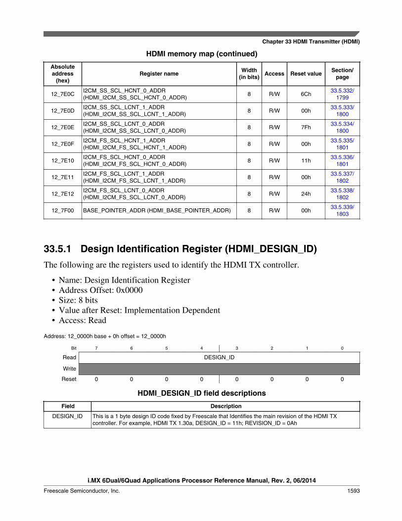
HDMI memory map (continued)
Absoluteaddress
(hex)Register name Width
(in bits) Access Reset value Section/page
12_7E0CI2CM_SS_SCL_HCNT_0_ADDR(HDMI_I2CM_SS_SCL_HCNT_0_ADDR)
8 R/W 6Ch33.5.332/
1799
12_7E0DI2CM_SS_SCL_LCNT_1_ADDR(HDMI_I2CM_SS_SCL_LCNT_1_ADDR)
8 R/W 00h33.5.333/
1800
12_7E0EI2CM_SS_SCL_LCNT_0_ADDR(HDMI_I2CM_SS_SCL_LCNT_0_ADDR)
8 R/W 7Fh33.5.334/
1800
12_7E0FI2CM_FS_SCL_HCNT_1_ADDR(HDMI_I2CM_FS_SCL_HCNT_1_ADDR)
8 R/W 00h33.5.335/
1801
12_7E10I2CM_FS_SCL_HCNT_0_ADDR(HDMI_I2CM_FS_SCL_HCNT_0_ADDR)
8 R/W 11h33.5.336/
1801
12_7E11I2CM_FS_SCL_LCNT_1_ADDR(HDMI_I2CM_FS_SCL_LCNT_1_ADDR)
8 R/W 00h33.5.337/
1802
12_7E12I2CM_FS_SCL_LCNT_0_ADDR(HDMI_I2CM_FS_SCL_LCNT_0_ADDR)
8 R/W 24h33.5.338/
1802
12_7F00 BASE_POINTER_ADDR (HDMI_BASE_POINTER_ADDR) 8 R/W 00h33.5.339/
1803
33.5.1 Design Identification Register (HDMI_DESIGN_ID)The following are the registers used to identify the HDMI TX controller.
• Name: Design Identification Register• Address Offset: 0x0000• Size: 8 bits• Value after Reset: Implementation Dependent• Access: Read
Address: 12_0000h base + 0h offset = 12_0000h
Bit 7 6 5 4 3 2 1 0
Read DESIGN_ID
Write
Reset 0 0 0 0 0 0 0 0
HDMI_DESIGN_ID field descriptions
Field Description
DESIGN_ID This is a 1 byte design ID code fixed by Freescale that Identifies the main revision of the HDMI TXcontroller. For example, HDMI TX 1.30a, DESIGN_ID = 11h; REVISION_ID = 0Ah
Chapter 33 HDMI Transmitter (HDMI)
i.MX 6Dual/6Quad Applications Processor Reference Manual, Rev. 2, 06/2014
Freescale Semiconductor, Inc. 1593

33.5.2 Revision Identification Register (HDMI_REVISION_ID)
• Name: Revision Identification Register• Address Offset: 0x0001• Size: 8 bits• Value after Reset: Implementation Dependent• Access: Read
Address: 12_0000h base + 1h offset = 12_0001h
Bit 7 6 5 4 3 2 1 0
Read REVISION_ID
Write
Reset 0 0 0 0 0 0 0 0
HDMI_REVISION_ID field descriptions
Field Description
REVISION_ID This is a one byte revision ID code fixed by Freescale that Identifies the main revision of the HDMI TXcontroller. For example, HDMI TX 1.30a, DESIGN_ID = 12h; REVISION_ID = 0Ah
33.5.3 Product Identification Register 0 (HDMI_PRODUCT_ID0)
• Name: Product Identification Register 0• Address Offset: 0x0002• Size: 8 bits• Value after Reset: Implementation Dependent• Access: Read
Address: 12_0000h base + 2h offset = 12_0002h
Bit 7 6 5 4 3 2 1 0
Read PRODUCT_ID0
Write
Reset 0 0 0 0 0 0 0 0
HDMI_PRODUCT_ID0 field descriptions
Field Description
PRODUCT_ID0 This one byte fixed code Identifies Freescale's product line ("A0h" for HDMI TX products).
HDMI Memory Map/Register Definition
i.MX 6Dual/6Quad Applications Processor Reference Manual, Rev. 2, 06/2014
1594 Freescale Semiconductor, Inc.

33.5.4 Product Identification Register 1 (HDMI_PRODUCT_ID1)
• Name: Product Identification Register 1• Address Offset: 0x0003• Size: 8 bits• Value after Reset: Implementation Dependent• Access: Read
Address: 12_0000h base + 3h offset = 12_0003h
Bit 7 6 5 4 3 2 1 0
Read PRODUCT_ID1
Write
Reset 0 0 0 0 0 0 0 0
HDMI_PRODUCT_ID1 field descriptions
Field Description
PRODUCT_ID1 This one byte fixed code identifies Freescale's product line according to:
01h HDMI TX Controller
C1h HDMI TX Controller with HDCP encryption engine
33.5.5 Configuration Identification Register 0(HDMI_CONFIG0_ID)
• Name: Configuration Identification Register 0• Address Offset: 0x0004• Size: 8 bits• Value after Reset: Implementation Dependent• Access: Read
Address: 12_0000h base + 4h offset = 12_0004h
Bit 7 6 5 4 3 2 1 0
Read prepen audhbr audspdif audi2s hdmi14 csc cec hdcp
Write
Reset 0 0 0 0 0 0 0 0
Chapter 33 HDMI Transmitter (HDMI)
i.MX 6Dual/6Quad Applications Processor Reference Manual, Rev. 2, 06/2014
Freescale Semiconductor, Inc. 1595

HDMI_CONFIG0_ID field descriptions
Field Description
7prepen
Indicates if it is possible to use internal pixel repetition
6audhbr
Indicates if HBR interface is present
5audspdif
Indicates if SPDIF interface is present
4audi2s
Indicates if I2S interface is present
3hdmi14
Indicates if HDMI 1.4 features are present
2csc
Indicates if Color Space Conversion block is present
1cec
Indicates if CEC is present
0hdcp
Indicates if HDCP is present
33.5.6 Configuration Identification Register 1(HDMI_CONFIG1_ID)
• Name: Configuration Identification Register 1• Address Offset: 0x0005• Size: 8 bits• Value after Reset: Implementation Dependent• Access: Read
Address: 12_0000h base + 5h offset = 12_0005h
Bit 7 6 5 4 3 2 1 0
ReadReserved
confsfrdir confi2c confocp confapb confahb
Write
Reset 0 0 0 0 0 0 0 0
HDMI_CONFIG1_ID field descriptions
Field Description
7–5-
This field is reserved.
4confsfrdir
Indicates that configuration interface is SFR interface
3confi2c
Indicates that configuration interface is I2C interface
Table continues on the next page...
HDMI Memory Map/Register Definition
i.MX 6Dual/6Quad Applications Processor Reference Manual, Rev. 2, 06/2014
1596 Freescale Semiconductor, Inc.

HDMI_CONFIG1_ID field descriptions (continued)
Field Description
2confocp
Indicates that configuration interface is OCP interface
1confapb
Indicates that configuration interface is APB interface
0confahb
Indicates that configuration interface is AHB interface
33.5.7 Configuration Identification Register 2(HDMI_CONFIG2_ID)
• Name: Configuration Identification Register 2• Address Offset: 0x0006• Size: 8 bits• Value after Reset: Implementation Dependent• Access: Read
Address: 12_0000h base + 6h offset = 12_0006h
Bit 7 6 5 4 3 2 1 0
Read phytype
Write
Reset 0 0 0 0 0 0 0 0
HDMI_CONFIG2_ID field descriptions
Field Description
phytype Indicates the type of PHY interface selected:
00h Legacy PHY (HDMI TX PHY)
F2h PHY_Gen2 (HDMI 3D TX PHY)
E2h PHY_Gen2 (HDMI 3D TX PHY) + HEAC PHY
Chapter 33 HDMI Transmitter (HDMI)
i.MX 6Dual/6Quad Applications Processor Reference Manual, Rev. 2, 06/2014
Freescale Semiconductor, Inc. 1597

33.5.8 Configuration Identification Register 3(HDMI_CONFIG3_ID)
• Name: Configuration Identification Register 3• Address Offset: 0x0007• Size: 8 bits• Value after Reset: Implementation Dependent• Access: Read
Address: 12_0000h base + 7h offset = 12_0007h
Bit 7 6 5 4 3 2 1 0
ReadReserved
confgpaud
Write
Reset 0 0 0 0 0 0 0 0
HDMI_CONFIG3_ID field descriptions
Field Description
7–1-
This field is reserved.
0confgpaud
Indicates that configuration interface is Generic Parallel Audio (GPAUD) interface
33.5.9 Frame Composer Interrupt Status Register 0(HDMI_IH_FC_STAT0)
This section describes clear on write (1 to corresponding bit) status registers, whichcontain the following active-high, sticky bit interrupts.
HDMI TX introduces a new set of sticky bit mute control registers(IH_MUTE_FC_STAT0 to IH_MUTE_AHBDMAAUD_STAT0) that correspond to theinterrupt registers. You can ignore a sticky bit interrupt by setting the corresponding mutecontrol register bit to 1. This puts the global interrupt line on a higher priority than thesticky bit interrupt.
• Address Offset: 0x0100• Size: 8 bits• Value after Reset: 0x00• Access: Read/Clear on Write
HDMI Memory Map/Register Definition
i.MX 6Dual/6Quad Applications Processor Reference Manual, Rev. 2, 06/2014
1598 Freescale Semiconductor, Inc.
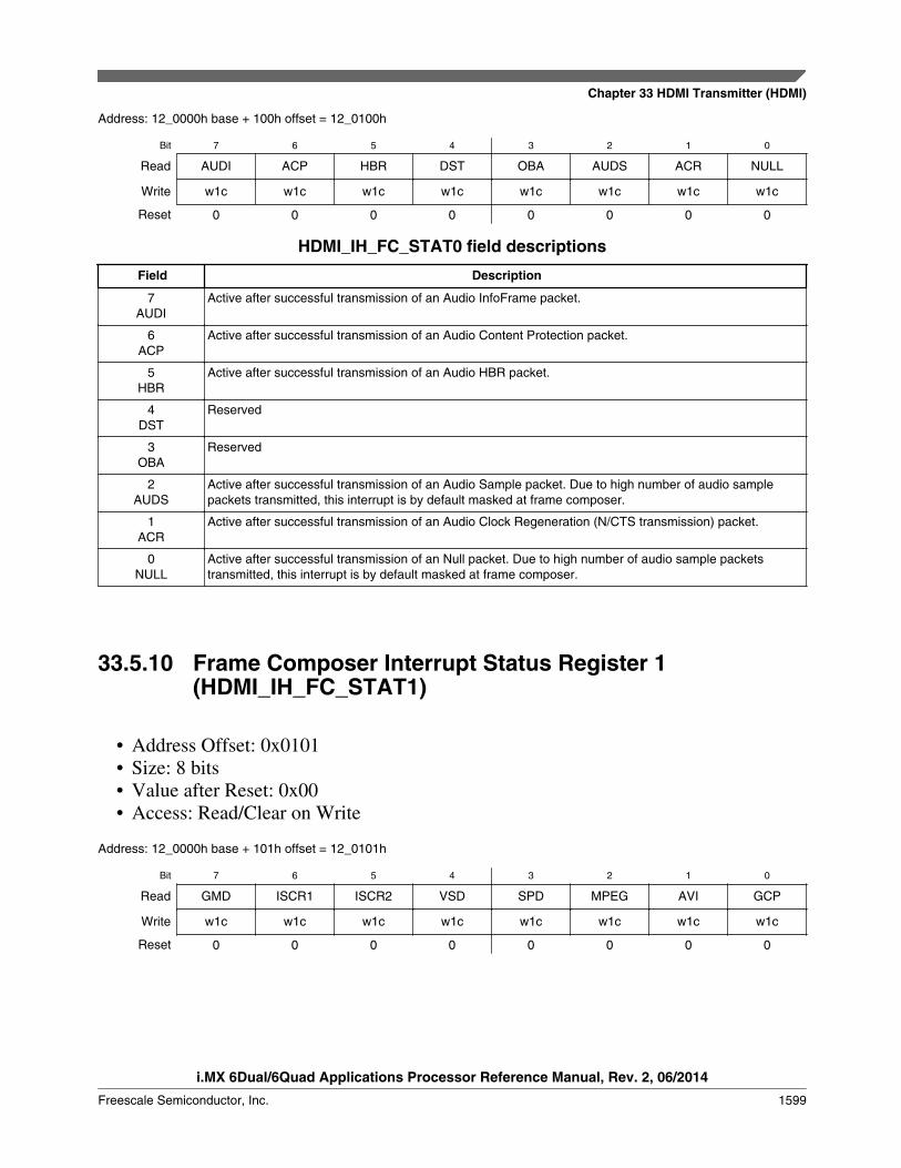
Address: 12_0000h base + 100h offset = 12_0100h
Bit 7 6 5 4 3 2 1 0
Read AUDI ACP HBR DST OBA AUDS ACR NULL
Write w1c w1c w1c w1c w1c w1c w1c w1c
Reset 0 0 0 0 0 0 0 0
HDMI_IH_FC_STAT0 field descriptions
Field Description
7AUDI
Active after successful transmission of an Audio InfoFrame packet.
6ACP
Active after successful transmission of an Audio Content Protection packet.
5HBR
Active after successful transmission of an Audio HBR packet.
4DST
Reserved
3OBA
Reserved
2AUDS
Active after successful transmission of an Audio Sample packet. Due to high number of audio samplepackets transmitted, this interrupt is by default masked at frame composer.
1ACR
Active after successful transmission of an Audio Clock Regeneration (N/CTS transmission) packet.
0NULL
Active after successful transmission of an Null packet. Due to high number of audio sample packetstransmitted, this interrupt is by default masked at frame composer.
33.5.10 Frame Composer Interrupt Status Register 1(HDMI_IH_FC_STAT1)
• Address Offset: 0x0101• Size: 8 bits• Value after Reset: 0x00• Access: Read/Clear on Write
Address: 12_0000h base + 101h offset = 12_0101h
Bit 7 6 5 4 3 2 1 0
Read GMD ISCR1 ISCR2 VSD SPD MPEG AVI GCP
Write w1c w1c w1c w1c w1c w1c w1c w1c
Reset 0 0 0 0 0 0 0 0
Chapter 33 HDMI Transmitter (HDMI)
i.MX 6Dual/6Quad Applications Processor Reference Manual, Rev. 2, 06/2014
Freescale Semiconductor, Inc. 1599
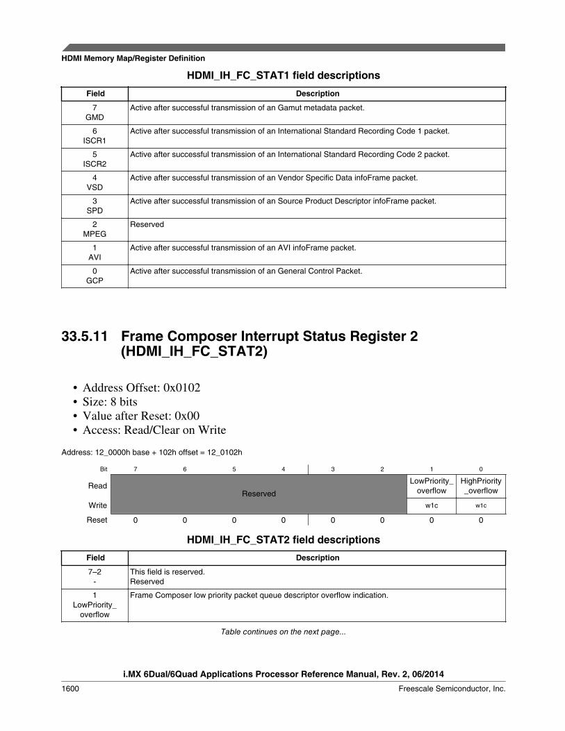
HDMI_IH_FC_STAT1 field descriptions
Field Description
7GMD
Active after successful transmission of an Gamut metadata packet.
6ISCR1
Active after successful transmission of an International Standard Recording Code 1 packet.
5ISCR2
Active after successful transmission of an International Standard Recording Code 2 packet.
4VSD
Active after successful transmission of an Vendor Specific Data infoFrame packet.
3SPD
Active after successful transmission of an Source Product Descriptor infoFrame packet.
2MPEG
Reserved
1AVI
Active after successful transmission of an AVI infoFrame packet.
0GCP
Active after successful transmission of an General Control Packet.
33.5.11 Frame Composer Interrupt Status Register 2(HDMI_IH_FC_STAT2)
• Address Offset: 0x0102• Size: 8 bits• Value after Reset: 0x00• Access: Read/Clear on Write
Address: 12_0000h base + 102h offset = 12_0102h
Bit 7 6 5 4 3 2 1 0
ReadReserved
LowPriority_overflow
HighPriority_overflow
Write w1c w1c
Reset 0 0 0 0 0 0 0 0
HDMI_IH_FC_STAT2 field descriptions
Field Description
7–2-
This field is reserved.Reserved
1LowPriority_
overflow
Frame Composer low priority packet queue descriptor overflow indication.
Table continues on the next page...
HDMI Memory Map/Register Definition
i.MX 6Dual/6Quad Applications Processor Reference Manual, Rev. 2, 06/2014
1600 Freescale Semiconductor, Inc.
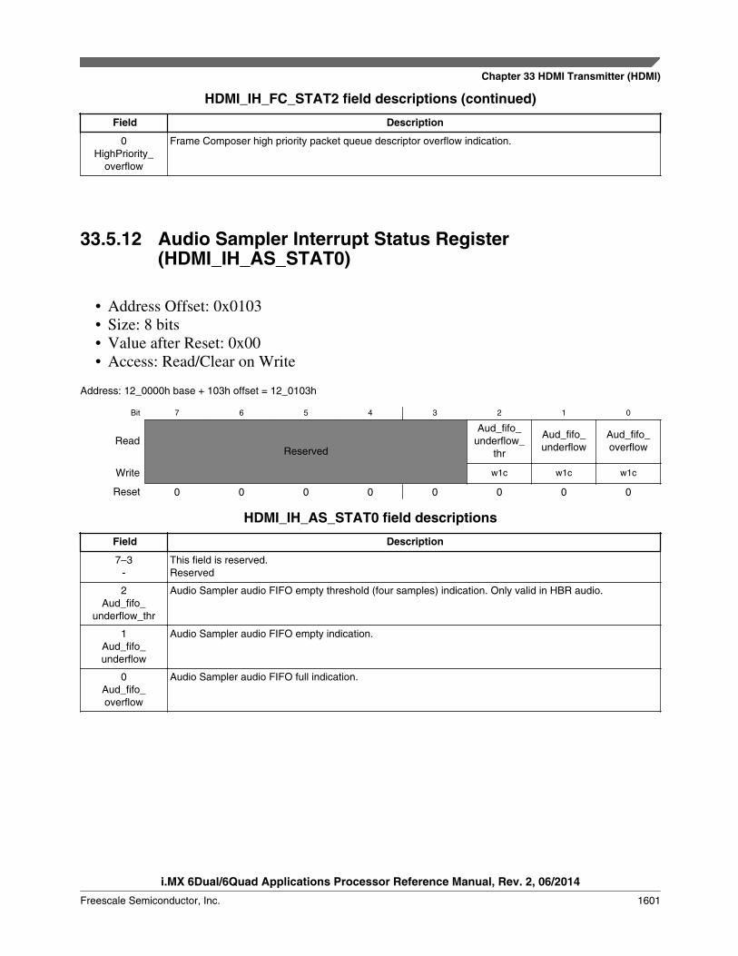
HDMI_IH_FC_STAT2 field descriptions (continued)
Field Description
0HighPriority_
overflow
Frame Composer high priority packet queue descriptor overflow indication.
33.5.12 Audio Sampler Interrupt Status Register(HDMI_IH_AS_STAT0)
• Address Offset: 0x0103• Size: 8 bits• Value after Reset: 0x00• Access: Read/Clear on Write
Address: 12_0000h base + 103h offset = 12_0103h
Bit 7 6 5 4 3 2 1 0
ReadReserved
Aud_fifo_underflow_
thr
Aud_fifo_underflow
Aud_fifo_overflow
Write w1c w1c w1c
Reset 0 0 0 0 0 0 0 0
HDMI_IH_AS_STAT0 field descriptions
Field Description
7–3-
This field is reserved.Reserved
2Aud_fifo_
underflow_thr
Audio Sampler audio FIFO empty threshold (four samples) indication. Only valid in HBR audio.
1Aud_fifo_underflow
Audio Sampler audio FIFO empty indication.
0Aud_fifo_overflow
Audio Sampler audio FIFO full indication.
Chapter 33 HDMI Transmitter (HDMI)
i.MX 6Dual/6Quad Applications Processor Reference Manual, Rev. 2, 06/2014
Freescale Semiconductor, Inc. 1601

33.5.13 PHY Interface Interrupt Status Register(HDMI_IH_PHY_STAT0)
• Address Offset: 0x0104• Size: 8 bits• Value after Reset: 0x00• Access: Clear on Write/Read
Address: 12_0000h base + 104h offset = 12_0104h
Bit 7 6 5 4
ReadReserved
RX_SENSE3 RX_SENSE2
Write w1c w1c
Reset 0 0 0 0
Bit 3 2 1 0
Read RX_SENSE1 RX_SENSE0 TX_PHY_LOCK HDP
Write w1c w1c w1c w1c
Reset 0 0 0 0
HDMI_IH_PHY_STAT0 field descriptions
Field Description
7–6-
This field is reserved.Reserved
5RX_SENSE3
TX PHY RX_SENSE indication for driver 3. You may need to mask or change polarity of this interrupt afterit has become active.
4RX_SENSE2
TX PHY RX_SENSE indication for driver 2. You may need to mask or change polarity of this interrupt afterit has become active.
3RX_SENSE1
TX PHY RX_SENSE indication for driver 1. You may need to mask or change polarity of this interrupt afterit has become active.
2RX_SENSE0
TX PHY RX_SENSE indication for driver 0. You may need to mask or change polarity of this interrupt afterit has become active.
1TX_PHY_LOCK
TX PHY PLL lock indication. Please refer to PHY datasheet for more information. You may need to maskor change polarity of this interrupt after it has become active.
0HDP
HDMI Hot Plug Detect indication. You may need to mask or change polarity of this interrupt after it hasbecome active.
HDMI Memory Map/Register Definition
i.MX 6Dual/6Quad Applications Processor Reference Manual, Rev. 2, 06/2014
1602 Freescale Semiconductor, Inc.

33.5.14 E-DDC I2C Master Interrupt Status Register(HDMI_IH_I2CM_STAT0)
• Address Offset: 0x0105• Size: 8 bits• Value after Reset: 0x00• Access: Clear on Write/Read
Address: 12_0000h base + 105h offset = 12_0105h
Bit 7 6 5 4
ReadReserved
Write
Reset 0 0 0 0
Bit 3 2 1 0
ReadReserved
I2Cmasterdone I2CMASTER_ERROR
Write w1c w1c
Reset 0 0 0 0
HDMI_IH_I2CM_STAT0 field descriptions
Field Description
7–2-
This field is reserved.Reserved
1I2Cmasterdone
I2C Master done indication
0I2CMASTER_
ERROR
I2C Master error indication
Chapter 33 HDMI Transmitter (HDMI)
i.MX 6Dual/6Quad Applications Processor Reference Manual, Rev. 2, 06/2014
Freescale Semiconductor, Inc. 1603
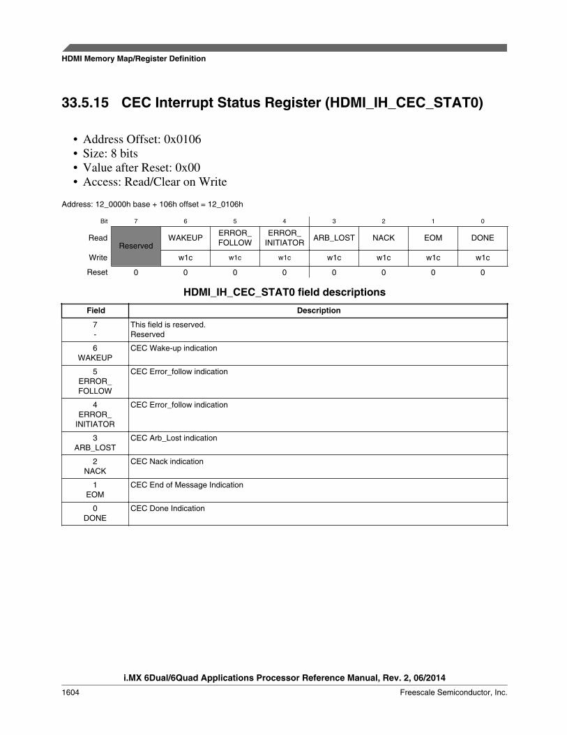
33.5.15 CEC Interrupt Status Register (HDMI_IH_CEC_STAT0)
• Address Offset: 0x0106• Size: 8 bits• Value after Reset: 0x00• Access: Read/Clear on Write
Address: 12_0000h base + 106h offset = 12_0106h
Bit 7 6 5 4 3 2 1 0
ReadReserved
WAKEUPERROR_FOLLOW
ERROR_INITIATOR
ARB_LOST NACK EOM DONE
Write w1c w1c w1c w1c w1c w1c w1c
Reset 0 0 0 0 0 0 0 0
HDMI_IH_CEC_STAT0 field descriptions
Field Description
7-
This field is reserved.Reserved
6WAKEUP
CEC Wake-up indication
5ERROR_FOLLOW
CEC Error_follow indication
4ERROR_
INITIATOR
CEC Error_follow indication
3ARB_LOST
CEC Arb_Lost indication
2NACK
CEC Nack indication
1EOM
CEC End of Message Indication
0DONE
CEC Done Indication
HDMI Memory Map/Register Definition
i.MX 6Dual/6Quad Applications Processor Reference Manual, Rev. 2, 06/2014
1604 Freescale Semiconductor, Inc.

33.5.16 Video Packetizer Interrupt Status Register(HDMI_IH_VP_STAT0)
• Address Offset: 0x0107• Size: 8 bits• Value after Reset: 0x00• Access: Read/Clear on Write
Address: 12_0000h base + 107h offset = 12_0107h
Bit 7 6 5 4
Read fifofullrepet fifoemptyrepet fifofullpp fifoemptypp
Write w1c w1c w1c w1c
Reset 0 0 0 0
Bit 3 2 1 0
Read fifofullremap fifoemptyremap fifofullbyp fifoemptybyp
Write w1c w1c w1c w1c
Reset 0 0 0 0
HDMI_IH_VP_STAT0 field descriptions
Field Description
7fifofullrepet
Video packetizer pixel repeater FIFO full interrupt
6fifoemptyrepet
Video packetizer pixel repeater FIFO empty interrupt
5fifofullpp
Video packetizer pixel packing FIFO full interrupt
4fifoemptypp
Video packetizer pixel packing FIFO empty interrupt
3fifofullremap
Video packetizer pixel YCC 422 re-mapper FIFO full interrupt
2fifoemptyremap
Video packetizer pixel YCC 422 re-mapper FIFO empty interrupt
1fifofullbyp
Video packetizer 8-bit bypass fifo full interrupt
0fifoemptybyp
Video packetizer 8-bit bypass fifo empty interrupt
Chapter 33 HDMI Transmitter (HDMI)
i.MX 6Dual/6Quad Applications Processor Reference Manual, Rev. 2, 06/2014
Freescale Semiconductor, Inc. 1605
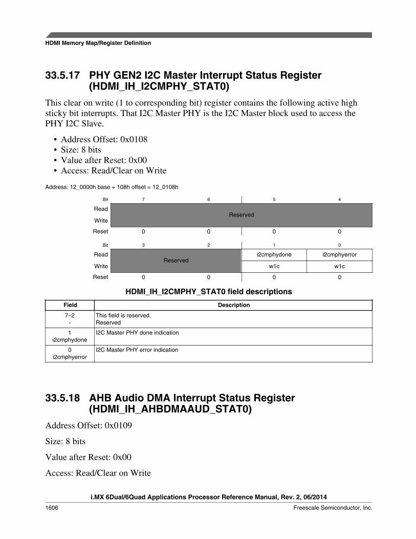
33.5.17 PHY GEN2 I2C Master Interrupt Status Register(HDMI_IH_I2CMPHY_STAT0)
This clear on write (1 to corresponding bit) register contains the following active highsticky bit interrupts. That I2C Master PHY is the I2C Master block used to access thePHY I2C Slave.
• Address Offset: 0x0108• Size: 8 bits• Value after Reset: 0x00• Access: Read/Clear on Write
Address: 12_0000h base + 108h offset = 12_0108h
Bit 7 6 5 4
ReadReserved
Write
Reset 0 0 0 0
Bit 3 2 1 0
ReadReserved
i2cmphydone i2cmphyerror
Write w1c w1c
Reset 0 0 0 0
HDMI_IH_I2CMPHY_STAT0 field descriptions
Field Description
7–2-
This field is reserved.Reserved
1i2cmphydone
I2C Master PHY done indication
0i2cmphyerror
I2C Master PHY error indication
33.5.18 AHB Audio DMA Interrupt Status Register(HDMI_IH_AHBDMAAUD_STAT0)
Address Offset: 0x0109
Size: 8 bits
Value after Reset: 0x00
Access: Read/Clear on Write
HDMI Memory Map/Register Definition
i.MX 6Dual/6Quad Applications Processor Reference Manual, Rev. 2, 06/2014
1606 Freescale Semiconductor, Inc.

Address: 12_0000h base + 109h offset = 12_0109h
Bit 7 6 5 4
ReadReserved
ahbdmaaud_interrorahbdmaaud_
intlostownership
Write w1c w1c
Reset 0 0 0 0
Bit 3 2 1 0
Read ahbdmaaud_intretrysplit ahbdmaaud_intdone ahbdmaaud_intbufffullahbdmaaud_intbuffempty
Write w1c w1c w1c w1c
Reset 0 0 0 0
HDMI_IH_AHBDMAAUD_STAT0 field descriptions
Field Description
7–6-
This field is reserved.Reserved
5ahbdmaaud_interror
AHB audio DMA error interrupt
4ahbdmaaud_
intlostownership
AHB audio DMA lost ownership interrupt
3ahbdmaaud_intretrysplit
AHB audio DMA RETRY/SPLIT interrupt
2ahbdmaaud_intdone
AHB audio DMA done interrupt
1ahbdmaaud_
intbufffull
AHB audio DMA Buffer full interrupt
0ahbdmaaud_intbuffempty
AHB audio DMA Buffer empty interrupt
Chapter 33 HDMI Transmitter (HDMI)
i.MX 6Dual/6Quad Applications Processor Reference Manual, Rev. 2, 06/2014
Freescale Semiconductor, Inc. 1607

33.5.19 Frame Composer Interrupt Mute Control Register 0(HDMI_IH_MUTE_FC_STAT0)
• Address Offset: 0x0180• Size: 8 bits• Value after Reset: 0x00• Access: Read/Write
Address: 12_0000h base + 180h offset = 12_0180h
Bit 7 6 5 4 3 2 1 0
Read AUDI ACP HBR DST OBA AUDS ACR NULLWriteReset 0 0 0 0 0 0 0 0
HDMI_IH_MUTE_FC_STAT0 field descriptions
Field Description
7AUDI
When set to 1, mutes IH_ FC_STAT0[7]
6ACP
When set to 1, mutes IH_ FC_STAT0[6]
5HBR
When set to 1, mutes IH_ FC_STAT0[5]
4DST
When set to 1, mutes IH_ FC_STAT0[4]
3OBA
When set to 1, mutes IH_ FC_STAT0[3]
2AUDS
When set to 1, mutes IH_ FC_STAT0[2]
1ACR
When set to 1, mutes IH_ FC_STAT0[1]
0NULL
When set to 1, mutes IH_ FC_STAT0[0]
HDMI Memory Map/Register Definition
i.MX 6Dual/6Quad Applications Processor Reference Manual, Rev. 2, 06/2014
1608 Freescale Semiconductor, Inc.

33.5.20 Frame Composer Interrupt Mute Control Register 1(HDMI_IH_MUTE_FC_STAT1)
• Address Offset: 0x0181• Size: 8 bits• Value after Reset: 0x00• Access: Read/Write
Address: 12_0000h base + 181h offset = 12_0181h
Bit 7 6 5 4 3 2 1 0
Read GMD ISCR1 ISCR2 VSD SPD MPEG AVI GCPWriteReset 0 0 0 0 0 0 0 0
HDMI_IH_MUTE_FC_STAT1 field descriptions
Field Description
7GMD
When set to 1, mutes IH_ FC_STAT1[7]
6ISCR1
When set to 1, mutes IH_ FC_STAT1[6]
5ISCR2
When set to 1, mutes IH_ FC_STAT1[5]
4VSD
When set to 1, mutes IH_ FC_STAT1[4]
3SPD
When set to 1, mutes IH_ FC_STAT1[3]
2MPEG
When set to 1, mutes IH_ FC_STAT1[2]
1AVI
When set to 1, mutes IH_ FC_STAT1[1]
0GCP
When set to 1, mutes IH_ FC_STAT1[0]
Chapter 33 HDMI Transmitter (HDMI)
i.MX 6Dual/6Quad Applications Processor Reference Manual, Rev. 2, 06/2014
Freescale Semiconductor, Inc. 1609

33.5.21 Frame Composer Interrupt Mute Control Register 2(HDMI_IH_MUTE_FC_STAT2)
• Address Offset: 0x0182• Size: 8 bits• Value after Reset: 0x00• Access: Read/Write
Address: 12_0000h base + 182h offset = 12_0182h
Bit 7 6 5 4 3 2 1 0
ReadReserved
LowPriority_overflow
HighPriority_overflowWrite
Reset 0 0 0 0 0 0 0 0
HDMI_IH_MUTE_FC_STAT2 field descriptions
Field Description
7–2-
This field is reserved.Reserved
1LowPriority_
overflow
When set to 1, mutes IH_ FC_STAT2[1]
0HighPriority_
overflow
When set to 1, mutes IH_ FC_STAT2[0]
33.5.22 Audio Sampler Interrupt Mute Control Register 0(HDMI_IH_MUTE_AS_STAT0)
• Address Offset: 0x0183• Size: 8 bits• Value after Reset: 0x00• Access: Read/Write
Address: 12_0000h base + 183h offset = 12_0183h
Bit 7 6 5 4 3 2 1 0
Read
ReservedAud_fifo_
underflow_thr
Aud_fifo_underflow
Aud_fifo_overflowWrite
Reset 0 0 0 0 0 0 0 0
HDMI Memory Map/Register Definition
i.MX 6Dual/6Quad Applications Processor Reference Manual, Rev. 2, 06/2014
1610 Freescale Semiconductor, Inc.
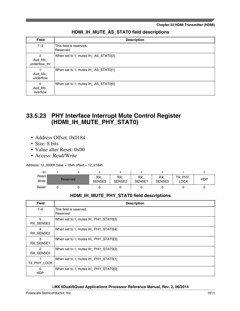
HDMI_IH_MUTE_AS_STAT0 field descriptions
Field Description
7–3-
This field is reserved.Reserved
2Aud_fifo_
underflow_thr
When set to 1, mutes IH_ AS_STAT0[2]
1Aud_fifo_underflow
When set to 1, mutes IH_ AS_STAT0[1]
0Aud_fifo_overflow
When set to 1, mutes IH_ AS_STAT0[0]
33.5.23 PHY Interface Interrupt Mute Control Register(HDMI_IH_MUTE_PHY_STAT0)
• Address Offset: 0x0184• Size: 8 bits• Value after Reset: 0x00• Access: Read/Write
Address: 12_0000h base + 184h offset = 12_0184h
Bit 7 6 5 4 3 2 1 0
ReadReserved
RX_SENSE3
RX_SENSE2
RX_SENSE1
RX_SENSE0
TX_PHY_LOCK
HDPWrite
Reset 0 0 0 0 0 0 0 0
HDMI_IH_MUTE_PHY_STAT0 field descriptions
Field Description
7–6-
This field is reserved.Reserved
5RX_SENSE3
When set to 1, mutes IH_ PHY_STAT0[5]
4RX_SENSE2
When set to 1, mutes IH_ PHY_STAT0[4]
3RX_SENSE1
When set to 1, mutes IH_ PHY_STAT0[3]
2RX_SENSE0
When set to 1, mutes IH_ PHY_STAT0[2]
1TX_PHY_LOCK
When set to 1, mutes IH_ PHY_STAT0[1]
0HDP
When set to 1, mutes IH_ PHY_STAT0[0]
Chapter 33 HDMI Transmitter (HDMI)
i.MX 6Dual/6Quad Applications Processor Reference Manual, Rev. 2, 06/2014
Freescale Semiconductor, Inc. 1611

33.5.24 E-DDC I2C Master Interrupt Mute Control Register(HDMI_IH_MUTE_I2CM_STAT0)
• Address Offset: 0x0185• Size: 8 bits• Value after Reset: 0x00• Access: Read/Write
Address: 12_0000h base + 185h offset = 12_0185h
Bit 7 6 5 4
Read ReservedWriteReset 0 0 0 0
Bit 3 2 1 0
Read Reserved I2Cmasterdone I2CMASTER_ERRORWriteReset 0 0 0 0
HDMI_IH_MUTE_I2CM_STAT0 field descriptions
Field Description
7–2-
This field is reserved.Reserved
1I2Cmasterdone
When set to 1, mutes IH_ I2CM_STAT0[1]
0I2CMASTER_
ERROR
When set to 1, mutes IH_ I2CM_STAT0[0]
33.5.25 CEC Interrupt Mute Control Register(HDMI_IH_MUTE_CEC_STAT0)
• Address Offset: 0x0186• Size: 8 bits• Value after Reset: 0x00• Access: Read/Write
Address: 12_0000h base + 186h offset = 12_0186h
Bit 7 6 5 4 3 2 1 0
ReadReserved WAKEUP
ERROR_FOLLOW
ERROR_INITIATOR
ARB_LOST NACK EOM DONEWrite
Reset 0 0 0 0 0 0 0 0
HDMI Memory Map/Register Definition
i.MX 6Dual/6Quad Applications Processor Reference Manual, Rev. 2, 06/2014
1612 Freescale Semiconductor, Inc.
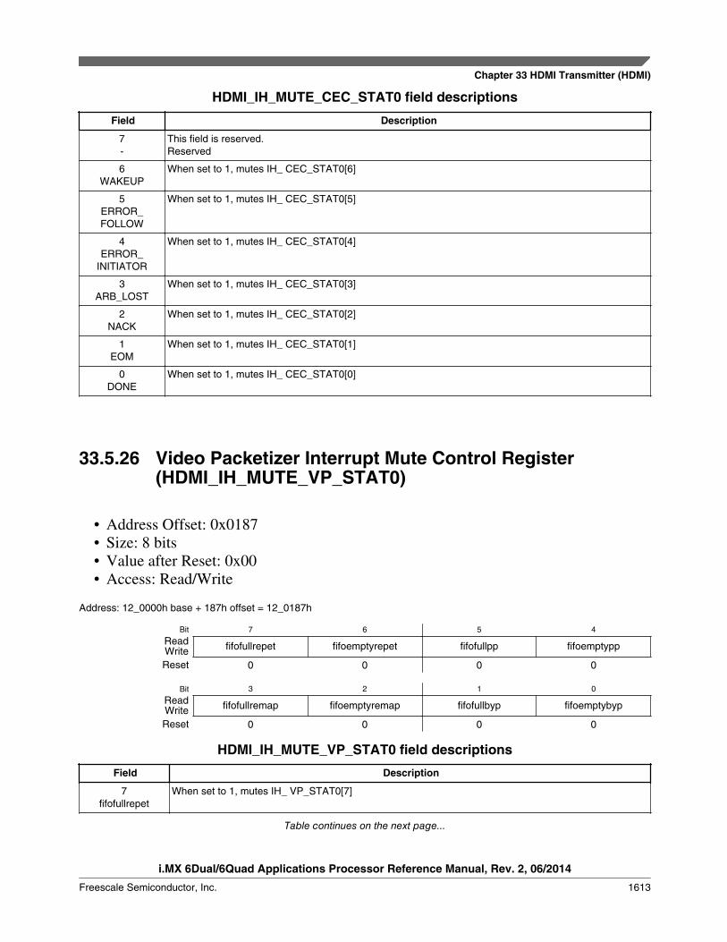
HDMI_IH_MUTE_CEC_STAT0 field descriptions
Field Description
7-
This field is reserved.Reserved
6WAKEUP
When set to 1, mutes IH_ CEC_STAT0[6]
5ERROR_FOLLOW
When set to 1, mutes IH_ CEC_STAT0[5]
4ERROR_
INITIATOR
When set to 1, mutes IH_ CEC_STAT0[4]
3ARB_LOST
When set to 1, mutes IH_ CEC_STAT0[3]
2NACK
When set to 1, mutes IH_ CEC_STAT0[2]
1EOM
When set to 1, mutes IH_ CEC_STAT0[1]
0DONE
When set to 1, mutes IH_ CEC_STAT0[0]
33.5.26 Video Packetizer Interrupt Mute Control Register(HDMI_IH_MUTE_VP_STAT0)
• Address Offset: 0x0187• Size: 8 bits• Value after Reset: 0x00• Access: Read/Write
Address: 12_0000h base + 187h offset = 12_0187h
Bit 7 6 5 4
Read fifofullrepet fifoemptyrepet fifofullpp fifoemptyppWriteReset 0 0 0 0
Bit 3 2 1 0
Read fifofullremap fifoemptyremap fifofullbyp fifoemptybypWriteReset 0 0 0 0
HDMI_IH_MUTE_VP_STAT0 field descriptions
Field Description
7fifofullrepet
When set to 1, mutes IH_ VP_STAT0[7]
Table continues on the next page...
Chapter 33 HDMI Transmitter (HDMI)
i.MX 6Dual/6Quad Applications Processor Reference Manual, Rev. 2, 06/2014
Freescale Semiconductor, Inc. 1613

HDMI_IH_MUTE_VP_STAT0 field descriptions (continued)
Field Description
6fifoemptyrepet
When set to 1, mutes IH_ VP_STAT0[6]
5fifofullpp
When set to 1, mutes IH_ VP_STAT0[5]
4fifoemptypp
When set to 1, mutes IH_ VP_STAT0[4]
3fifofullremap
When set to 1, mutes IH_ VP_STAT0[3]
2fifoemptyremap
When set to 1, mutes IH_ VP_STAT0[2]
1fifofullbyp
When set to 1, mutes IH_ VP_STAT0[1]
0fifoemptybyp
When set to 1, mutes IH_ VP_STAT0[0]
33.5.27 PHY GEN 2 I2C Master Interrupt Mute Control Register(HDMI_IH_MUTE_I2CMPHY_STAT0)
• Address Offset: 0x0188• Size: 8 bits• Value after Reset: 0x00• Access: Read/Write
Address: 12_0000h base + 188h offset = 12_0188h
Bit 7 6 5 4
Read ReservedWriteReset 0 0 0 0
Bit 3 2 1 0
Read Reserved i2cmphydone i2cmphyerrorWriteReset 0 0 0 0
HDMI_IH_MUTE_I2CMPHY_STAT0 field descriptions
Field Description
7–2-
This field is reserved.Reserved
1i2cmphydone
When set to 1, mutes IH_ I2CMPHY_STAT0[1]
0i2cmphyerror
When set to 1, mutes IH_ I2CMPHY_STAT0[0]
HDMI Memory Map/Register Definition
i.MX 6Dual/6Quad Applications Processor Reference Manual, Rev. 2, 06/2014
1614 Freescale Semiconductor, Inc.

33.5.28 AHB Audio DMA Interrupt Mute Control Register(HDMI_IH_MUTE_AHBDMAAUD_STAT0)
• Address Offset: 0x0189• Size: 8 bits• Value after Reset: 0x00• Access: Read/Write
Address: 12_0000h base + 189h offset = 12_0189h
Bit 7 6 5 4
ReadReserved ahbdmaaud_interror
ahbdmaaud_intlostownershipWrite
Reset 0 0 0 0
Bit 3 2 1 0
Readahbdmaaud_intretrysplit ahbdmaaud_intdone ahbdmaaud_intbufffull
ahbdmaaud_intbuffemptyWrite
Reset 0 0 0 0
HDMI_IH_MUTE_AHBDMAAUD_STAT0 field descriptions
Field Description
7–6-
This field is reserved.Reserved
5ahbdmaaud_interror
When set to 1, mutes IH_AHBDMAAUD_STAT0[5]
4ahbdmaaud_
intlostownership
When set to 1, mutes IH_AHBDMAAUD_STAT0[4]
3ahbdmaaud_intretrysplit
When set to 1, mutes IH_AHBDMAAUD_STAT0[3]
2ahbdmaaud_intdone
When set to 1, mutes IH_AHBDMAAUD_STAT0[2]
1ahbdmaaud_
intbufffull
When set to 1, mutes IH_AHBDMAAUD_STAT0[1]
0ahbdmaaud_intbuffempty
When set to 1, mutes IH_AHBDMAAUD_STAT0[0]
Chapter 33 HDMI Transmitter (HDMI)
i.MX 6Dual/6Quad Applications Processor Reference Manual, Rev. 2, 06/2014
Freescale Semiconductor, Inc. 1615

33.5.29 Global Interrupt Mute Control Register (HDMI_IH_MUTE)
• Address Offset: 0x01FF• Size: 8 bits• Value after Reset: 0x03• Access: Read/Write
Address: 12_0000h base + 1FFh offset = 12_01FFh
Bit 7 6 5 4 3 2 1 0
Read
Reservedmute_
wakeup_interrupt
mute_all_interruptWrite
Reset 0 0 0 0 0 0 1 1
HDMI_IH_MUTE field descriptions
Field Description
7–2rsvd
This field is reserved.
1mute_wakeup_
interrupt
When set to 1, mutes the wake-up interrupt line.
The sticky bit interrupt continues with its state; only the wake up interrupt line is muted.
0mute_all_interrupt
When set to 1, mutes the main interrupt line (where all interrupts are ORed).
The sticky bit interrupts continue with their state; only the main interrupt line will be muted.
33.5.30 Video Input Mapping and Internal Data EnableConfiguration Register (HDMI_TX_INVID0)
This registers contains the input video mapping code as defined in Table 2-1.
• Address Offset: 0x0200• Size: 8 bits• Value after Reset: 0x01• Access: Read/Write
Address: 12_0000h base + 200h offset = 12_0200h
Bit 7 6 5 4 3 2 1 0
Read internal_de_generator
Reserved video_mappingWrite
Reset 0 0 0 0 0 0 0 1
HDMI Memory Map/Register Definition
i.MX 6Dual/6Quad Applications Processor Reference Manual, Rev. 2, 06/2014
1616 Freescale Semiconductor, Inc.
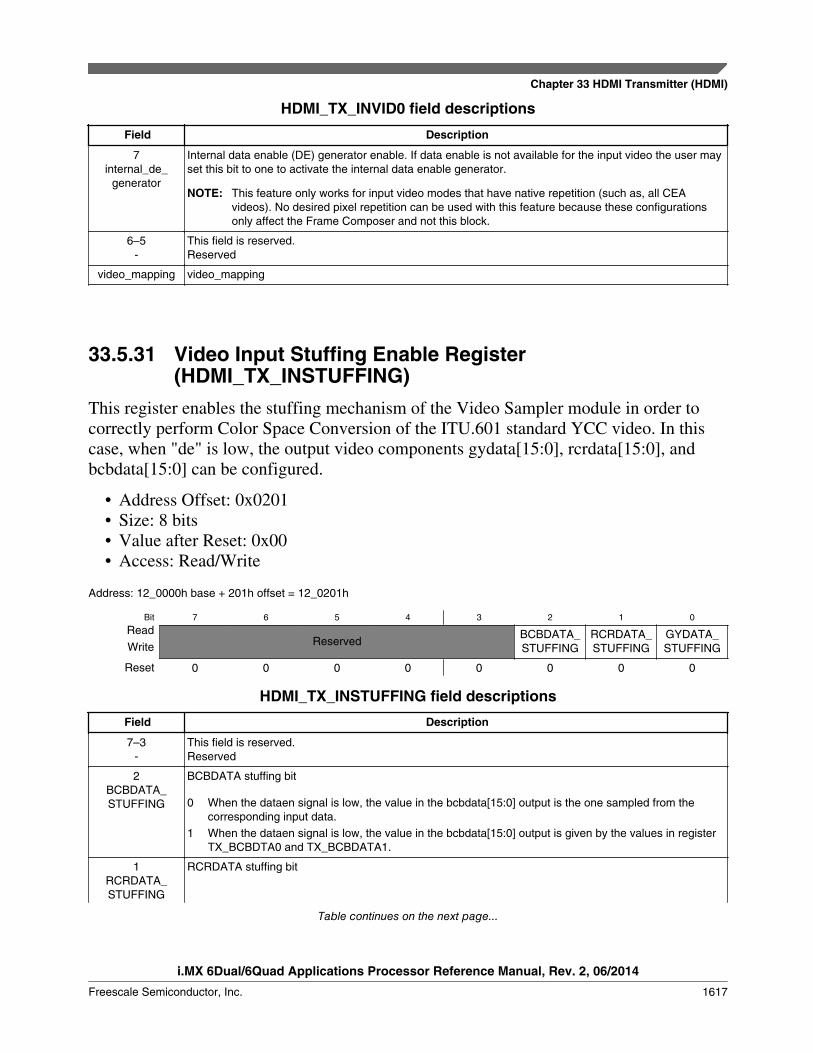
HDMI_TX_INVID0 field descriptions
Field Description
7internal_de_
generator
Internal data enable (DE) generator enable. If data enable is not available for the input video the user mayset this bit to one to activate the internal data enable generator.
NOTE: This feature only works for input video modes that have native repetition (such as, all CEAvideos). No desired pixel repetition can be used with this feature because these configurationsonly affect the Frame Composer and not this block.
6–5-
This field is reserved.Reserved
video_mapping video_mapping
33.5.31 Video Input Stuffing Enable Register(HDMI_TX_INSTUFFING)
This register enables the stuffing mechanism of the Video Sampler module in order tocorrectly perform Color Space Conversion of the ITU.601 standard YCC video. In thiscase, when "de" is low, the output video components gydata[15:0], rcrdata[15:0], andbcbdata[15:0] can be configured.
• Address Offset: 0x0201• Size: 8 bits• Value after Reset: 0x00• Access: Read/Write
Address: 12_0000h base + 201h offset = 12_0201h
Bit 7 6 5 4 3 2 1 0
ReadReserved
BCBDATA_STUFFING
RCRDATA_STUFFING
GYDATA_STUFFINGWrite
Reset 0 0 0 0 0 0 0 0
HDMI_TX_INSTUFFING field descriptions
Field Description
7–3-
This field is reserved.Reserved
2BCBDATA_STUFFING
BCBDATA stuffing bit
0 When the dataen signal is low, the value in the bcbdata[15:0] output is the one sampled from thecorresponding input data.
1 When the dataen signal is low, the value in the bcbdata[15:0] output is given by the values in registerTX_BCBDTA0 and TX_BCBDATA1.
1RCRDATA_STUFFING
RCRDATA stuffing bit
Table continues on the next page...
Chapter 33 HDMI Transmitter (HDMI)
i.MX 6Dual/6Quad Applications Processor Reference Manual, Rev. 2, 06/2014
Freescale Semiconductor, Inc. 1617
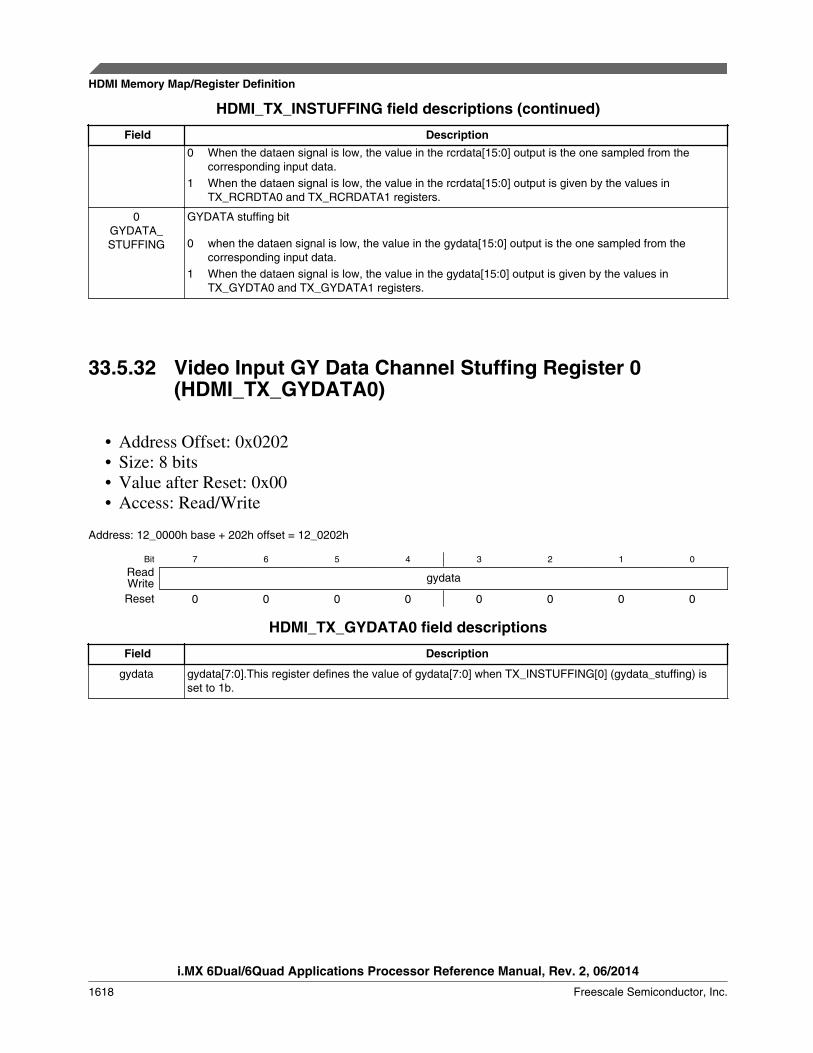
HDMI_TX_INSTUFFING field descriptions (continued)
Field Description0 When the dataen signal is low, the value in the rcrdata[15:0] output is the one sampled from the
corresponding input data.1 When the dataen signal is low, the value in the rcrdata[15:0] output is given by the values in
TX_RCRDTA0 and TX_RCRDATA1 registers.
0GYDATA_STUFFING
GYDATA stuffing bit
0 when the dataen signal is low, the value in the gydata[15:0] output is the one sampled from thecorresponding input data.
1 When the dataen signal is low, the value in the gydata[15:0] output is given by the values inTX_GYDTA0 and TX_GYDATA1 registers.
33.5.32 Video Input GY Data Channel Stuffing Register 0(HDMI_TX_GYDATA0)
• Address Offset: 0x0202• Size: 8 bits• Value after Reset: 0x00• Access: Read/Write
Address: 12_0000h base + 202h offset = 12_0202h
Bit 7 6 5 4 3 2 1 0
Read gydataWriteReset 0 0 0 0 0 0 0 0
HDMI_TX_GYDATA0 field descriptions
Field Description
gydata gydata[7:0].This register defines the value of gydata[7:0] when TX_INSTUFFING[0] (gydata_stuffing) isset to 1b.
HDMI Memory Map/Register Definition
i.MX 6Dual/6Quad Applications Processor Reference Manual, Rev. 2, 06/2014
1618 Freescale Semiconductor, Inc.
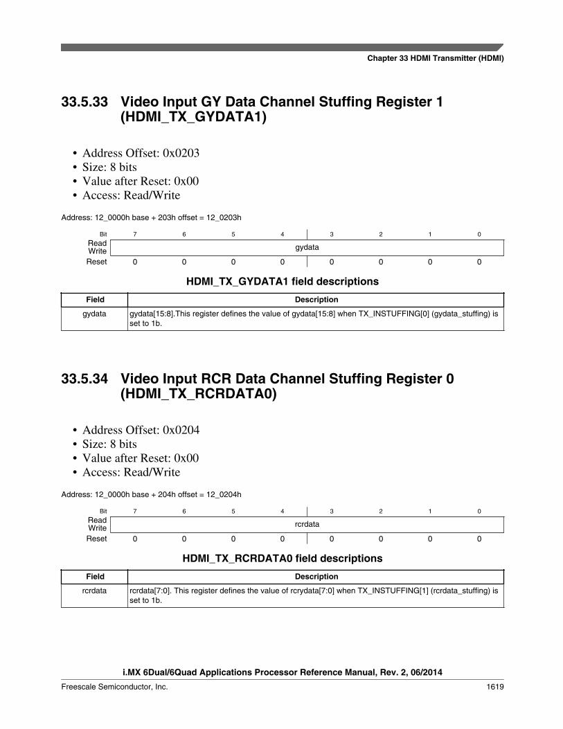
33.5.33 Video Input GY Data Channel Stuffing Register 1(HDMI_TX_GYDATA1)
• Address Offset: 0x0203• Size: 8 bits• Value after Reset: 0x00• Access: Read/Write
Address: 12_0000h base + 203h offset = 12_0203h
Bit 7 6 5 4 3 2 1 0
Read gydataWriteReset 0 0 0 0 0 0 0 0
HDMI_TX_GYDATA1 field descriptions
Field Description
gydata gydata[15:8].This register defines the value of gydata[15:8] when TX_INSTUFFING[0] (gydata_stuffing) isset to 1b.
33.5.34 Video Input RCR Data Channel Stuffing Register 0(HDMI_TX_RCRDATA0)
• Address Offset: 0x0204• Size: 8 bits• Value after Reset: 0x00• Access: Read/Write
Address: 12_0000h base + 204h offset = 12_0204h
Bit 7 6 5 4 3 2 1 0
Read rcrdataWriteReset 0 0 0 0 0 0 0 0
HDMI_TX_RCRDATA0 field descriptions
Field Description
rcrdata rcrdata[7:0]. This register defines the value of rcrydata[7:0] when TX_INSTUFFING[1] (rcrdata_stuffing) isset to 1b.
Chapter 33 HDMI Transmitter (HDMI)
i.MX 6Dual/6Quad Applications Processor Reference Manual, Rev. 2, 06/2014
Freescale Semiconductor, Inc. 1619

33.5.35 Video Input RCR Data Channel Stuffing Register 1(HDMI_TX_RCRDATA1)
• Address Offset: 0x0205• Size: 8 bits• Value after Reset: 0x00• Access: Read/Write
Address: 12_0000h base + 205h offset = 12_0205h
Bit 7 6 5 4 3 2 1 0
Read rcrdataWriteReset 0 0 0 0 0 0 0 0
HDMI_TX_RCRDATA1 field descriptions
Field Description
rcrdata rcrdata[15:8]. This register defines the value of rcrydata[15:8] when TX_INSTUFFING[1] (rcrdata_stuffing)is set to 1b.
33.5.36 Video Input RCB Data Channel Stuffing Register 0(HDMI_TX_BCBDATA0)
• Address Offset: 0x0206• Size: 8 bits• Value after Reset: 0x00• Access: Read/Write
Address: 12_0000h base + 206h offset = 12_0206h
Bit 7 6 5 4 3 2 1 0
Read bcbdataWriteReset 0 0 0 0 0 0 0 0
HDMI_TX_BCBDATA0 field descriptions
Field Description
bcbdata bcbdata[7:0]. This register defines the value of bcbdata[7:0] when TX_INSTUFFING[2] (bcbdata_stuffing)is set to 1b.
HDMI Memory Map/Register Definition
i.MX 6Dual/6Quad Applications Processor Reference Manual, Rev. 2, 06/2014
1620 Freescale Semiconductor, Inc.
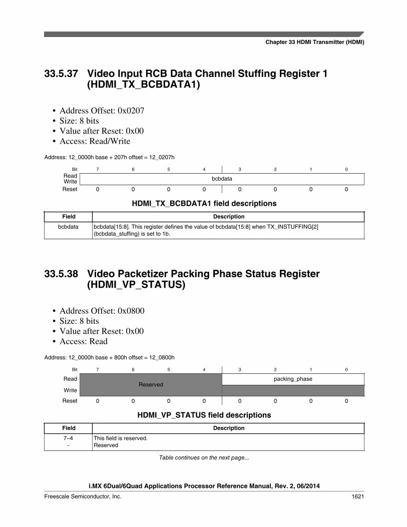
33.5.37 Video Input RCB Data Channel Stuffing Register 1(HDMI_TX_BCBDATA1)
• Address Offset: 0x0207• Size: 8 bits• Value after Reset: 0x00• Access: Read/Write
Address: 12_0000h base + 207h offset = 12_0207h
Bit 7 6 5 4 3 2 1 0
Read bcbdataWriteReset 0 0 0 0 0 0 0 0
HDMI_TX_BCBDATA1 field descriptions
Field Description
bcbdata bcbdata[15:8]. This register defines the value of bcbdata[15:8] when TX_INSTUFFING[2](bcbdata_stuffing) is set to 1b.
33.5.38 Video Packetizer Packing Phase Status Register(HDMI_VP_STATUS)
• Address Offset: 0x0800• Size: 8 bits• Value after Reset: 0x00• Access: Read
Address: 12_0000h base + 800h offset = 12_0800h
Bit 7 6 5 4 3 2 1 0
ReadReserved
packing_phase
Write
Reset 0 0 0 0 0 0 0 0
HDMI_VP_STATUS field descriptions
Field Description
7–4-
This field is reserved.Reserved
Table continues on the next page...
Chapter 33 HDMI Transmitter (HDMI)
i.MX 6Dual/6Quad Applications Processor Reference Manual, Rev. 2, 06/2014
Freescale Semiconductor, Inc. 1621

HDMI_VP_STATUS field descriptions (continued)
Field Description
packing_phase Read only register that holds the "packing phase" output by the Video packetizer block. For moreinformation about "packing" video data, refer to the HDMI1.4a specification. The register is updated attmds clock rate.
33.5.39 Video Packetizer Pixel Repetition and Color DepthRegister (HDMI_VP_PR_CD)
This register configures the Color Depth of the input video and Pixel repetition to applyto video.
• Address Offset: 0x0801• Size: 8 bits• Value after Reset: 0x00• Access: Read/Write
Address: 12_0000h base + 801h offset = 12_0801h
Bit 7 6 5 4 3 2 1 0
Read color_depth[3:0] desired_pr_factor[3:0]WriteReset 0 0 0 0 0 0 0 0
HDMI_VP_PR_CD field descriptions
Field Description
7–4color_depth[3:0]
Color depth configuration:
other Reserved. Not used.
0000 24 bits per pixel video (8 bit per component). 8-bit packing mode.0100 24 bits per pixel video (8 bit per component). 8-bit packing mode.0101 30 bits per pixel video (10 bit per component). 10-bit packing mode.0110 36 bits per pixel video (12 bit per component). 12-bit packing mode.0111 48 bits per pixel video (16 bit per component). 16-bit packing mode.
desired_pr_factor[3:0]
Desired pixel repetition factor configuration. The configured value sets H13T PHY PLL to multiply pixelclock by the factor in order to obtain the desired repetition clock. For the CEA modes some are alreadydefined with pixel repetition in the input video. So for CEA modes this shall be always 0. Shall only beused if the user wants to do pixel repetition using H13TCTRL core.
other Reserved. Not used.
0000 No pixel repetition (pixel sent only once)0001 Pixel sent 2 times (pixel repeated once)0010 Pixel sent 3 times0011 Pixel sent 4 times0100 Pixel sent 5 times0101 Pixel sent 6 times
Table continues on the next page...
HDMI Memory Map/Register Definition
i.MX 6Dual/6Quad Applications Processor Reference Manual, Rev. 2, 06/2014
1622 Freescale Semiconductor, Inc.

HDMI_VP_PR_CD field descriptions (continued)
Field Description
0110 Pixel sent 7 times0111 Pixel sent 8 times1000 Pixel sent 9 times1001 Pixel sent 10 times
33.5.40 Video Packetizer Stuffing and Default Packing PhaseRegister (HDMI_VP_STUFF)
This register controls the Pixel repetition, pixel packing and YCC422 stuffing.
• Address Offset: 0x0802• Size: 8 bits• Value after Reset: 0x00• Access: Read/Write
Address: 12_0000h base + 802h offset = 12_0802h
Bit 7 6 5 4
Read Reserved idefault_phase ifix_pp_to_lastWriteReset 0 0 0 0
Bit 3 2 1 0
Read icx_goto_p0_st ycc422_stuffing pp_stuffing pr_stuffingWriteReset 0 0 0 0
HDMI_VP_STUFF field descriptions
Field Description
7–6-
This field is reserved.Reserved
5idefault_phase
Controls the default phase packing machine used according to: "If the transmitted video format has timingsuch that the phase of the first pixel of every Video Data Period corresponds to pixel packing phase 0 (forexample, 10P0, 12P0, 16P0), the Source may set the Default_Phase bit in the GCP. The Sink may usethis bit to optimize it's filtering or handling of the PP field." (HDMI specification version 1.4a) This meansthat for10 bit mode the Htotal must be dividable by 4 and for 12 bit mode the Htotal must be dividable by2.
4ifix_pp_to_last
Reserved. Controls packing machine strategy.
3icx_goto_p0_st
Reserved. Controls packing machine strategy.
2ycc422_stuffing
YCC 422 remap stuffing control. For horizontal blanking:
0 YCC 422 remap block in direct mode (input blanking data goes directly to output).1 YCC 422 remap block in stuffing mode. When "de" goes to low the outputs are fixed to 0x00.
Table continues on the next page...
Chapter 33 HDMI Transmitter (HDMI)
i.MX 6Dual/6Quad Applications Processor Reference Manual, Rev. 2, 06/2014
Freescale Semiconductor, Inc. 1623

HDMI_VP_STUFF field descriptions (continued)
Field Description
1pp_stuffing
Pixel packing stuffing control
0 Pixel packing block in direct mode (input blanking data goes directly to output).1 Pixel packing block in stuffing mode. When "de_rep" goes to low the outputs are fixed to 0x00.
0pr_stuffing
Pixel repeater stuffing control
0 Pixel repeater block in direct mode (input blanking data goes directly to output).1 Pixel repeater block in stuffing mode. When "de" goes to low the outputs are fixed to 0x00.
33.5.41 Video Packetizer YCC422 Remapping Register(HDMI_VP_REMAP)
This register controls YCC422 remap of the Video Packetizer. For more informationabout YCC422 remap refer to HDMI 1.4a specification.
• Address Offset: 0x0803• Size: 8 bits• Value after Reset: 0x00• Access: Read/Write
Address: 12_0000h base + 803h offset = 12_0803h
Bit 7 6 5 4 3 2 1 0
Read Reserved ycc422_size[1:0]WriteReset 0 0 0 0 0 0 0 0
HDMI_VP_REMAP field descriptions
Field Description
7–2-
This field is reserved.Reserved
ycc422_size[1:0] YCC 422 remap input video size:
00 YCC 422 16-bit input video (8 bits per component).01 YCC 422 20-bit input video (10 bits per component).10 YCC 422 24-bit input video (12 bits per component).11 Reserved. Not used.
HDMI Memory Map/Register Definition
i.MX 6Dual/6Quad Applications Processor Reference Manual, Rev. 2, 06/2014
1624 Freescale Semiconductor, Inc.
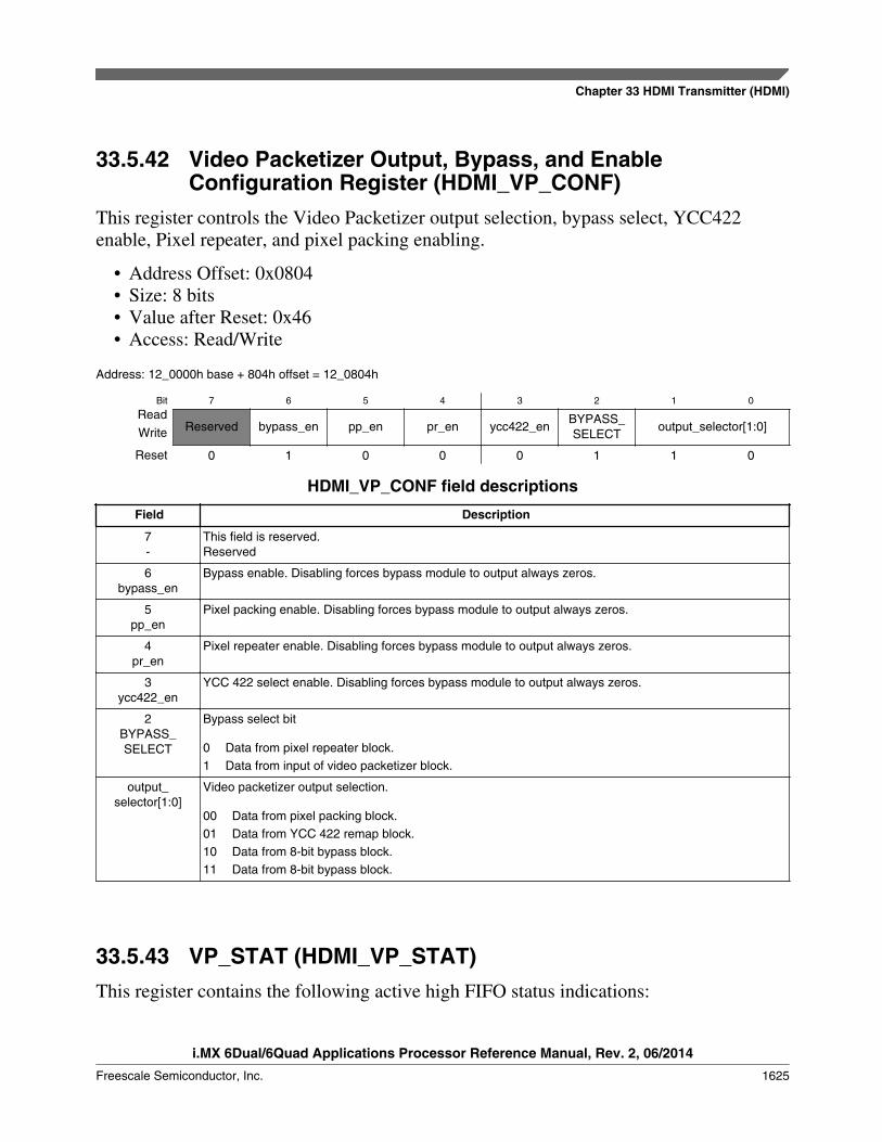
33.5.42 Video Packetizer Output, Bypass, and EnableConfiguration Register (HDMI_VP_CONF)
This register controls the Video Packetizer output selection, bypass select, YCC422enable, Pixel repeater, and pixel packing enabling.
• Address Offset: 0x0804• Size: 8 bits• Value after Reset: 0x46• Access: Read/Write
Address: 12_0000h base + 804h offset = 12_0804h
Bit 7 6 5 4 3 2 1 0
ReadReserved bypass_en pp_en pr_en ycc422_en
BYPASS_SELECT
output_selector[1:0]Write
Reset 0 1 0 0 0 1 1 0
HDMI_VP_CONF field descriptions
Field Description
7-
This field is reserved.Reserved
6bypass_en
Bypass enable. Disabling forces bypass module to output always zeros.
5pp_en
Pixel packing enable. Disabling forces bypass module to output always zeros.
4pr_en
Pixel repeater enable. Disabling forces bypass module to output always zeros.
3ycc422_en
YCC 422 select enable. Disabling forces bypass module to output always zeros.
2BYPASS_SELECT
Bypass select bit
0 Data from pixel repeater block.1 Data from input of video packetizer block.
output_selector[1:0]
Video packetizer output selection.
00 Data from pixel packing block.01 Data from YCC 422 remap block.10 Data from 8-bit bypass block.11 Data from 8-bit bypass block.
33.5.43 VP_STAT (HDMI_VP_STAT)This register contains the following active high FIFO status indications:
Chapter 33 HDMI Transmitter (HDMI)
i.MX 6Dual/6Quad Applications Processor Reference Manual, Rev. 2, 06/2014
Freescale Semiconductor, Inc. 1625
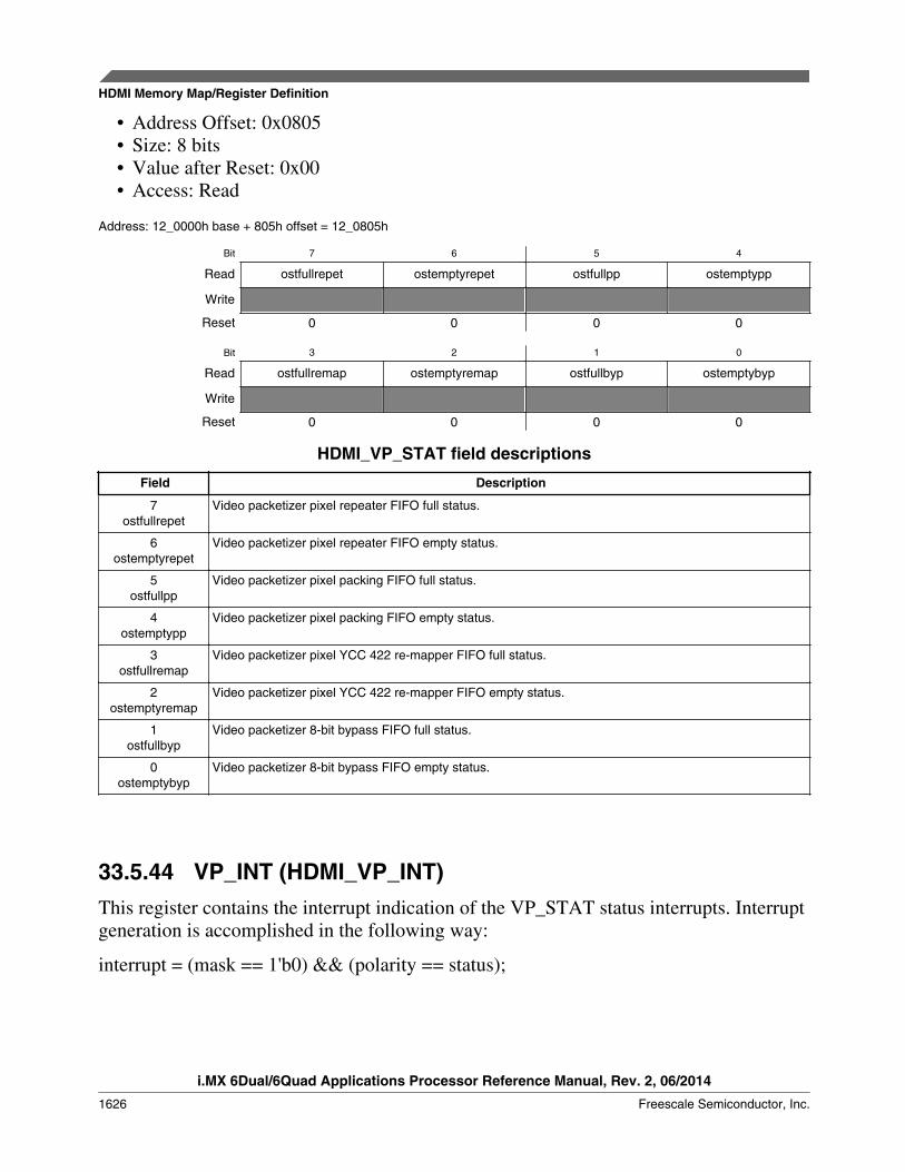
• Address Offset: 0x0805• Size: 8 bits• Value after Reset: 0x00• Access: Read
Address: 12_0000h base + 805h offset = 12_0805h
Bit 7 6 5 4
Read ostfullrepet ostemptyrepet ostfullpp ostemptypp
Write
Reset 0 0 0 0
Bit 3 2 1 0
Read ostfullremap ostemptyremap ostfullbyp ostemptybyp
Write
Reset 0 0 0 0
HDMI_VP_STAT field descriptions
Field Description
7ostfullrepet
Video packetizer pixel repeater FIFO full status.
6ostemptyrepet
Video packetizer pixel repeater FIFO empty status.
5ostfullpp
Video packetizer pixel packing FIFO full status.
4ostemptypp
Video packetizer pixel packing FIFO empty status.
3ostfullremap
Video packetizer pixel YCC 422 re-mapper FIFO full status.
2ostemptyremap
Video packetizer pixel YCC 422 re-mapper FIFO empty status.
1ostfullbyp
Video packetizer 8-bit bypass FIFO full status.
0ostemptybyp
Video packetizer 8-bit bypass FIFO empty status.
33.5.44 VP_INT (HDMI_VP_INT)This register contains the interrupt indication of the VP_STAT status interrupts. Interruptgeneration is accomplished in the following way:
interrupt = (mask == 1'b0) && (polarity == status);
HDMI Memory Map/Register Definition
i.MX 6Dual/6Quad Applications Processor Reference Manual, Rev. 2, 06/2014
1626 Freescale Semiconductor, Inc.

All this interrupts are forwarded to the Interrupt Handler sticky bit registers and afterORed to a single main interrupt line to micro controller. Assertion of this interruptimplies that data related with the corresponding packet has been sent through the HDMIinterface.
• Address Offset: 0x0806• Size: 8 bits• Value after Reset: 0x00• Access: Read
Address: 12_0000h base + 806h offset = 12_0806h
Bit 7 6 5 4
Read ointfullrepet ointemptyrepet ointfullpp ointemptypp
Write
Reset 0 0 0 0
Bit 3 2 1 0
Read ointfullremap ointemptyremap ointfullbyp ointemptybyp
Write
Reset 0 0 0 0
HDMI_VP_INT field descriptions
Field Description
7ointfullrepet
Video packetizer pixel repeater FIFO full status
6ointemptyrepet
Video packetizer pixel repeater FIFO empty status
5ointfullpp
Video packetizer pixel packing FIFO full status
4ointemptypp
Video packetizer pixel packing FIFO empty status
3ointfullremap
Video packetizer pixel YCC 422 re-mapper FIFO full status.
2ointemptyremap
Video packetizer pixel YCC 422 re-mapper FIFO empty status.
1ointfullbyp
Video packetizer 8-bit bypass FIFO full status.
0ointemptybyp
Video packetizer 8-bit bypass FIFO empty status.
33.5.45 Video Packetizer Interrupt Mask Register(HDMI_VP_MASK)
Mask register for generation of VP_INT interrupts.
Chapter 33 HDMI Transmitter (HDMI)
i.MX 6Dual/6Quad Applications Processor Reference Manual, Rev. 2, 06/2014
Freescale Semiconductor, Inc. 1627

• Address Offset: 0x0807• Size: 8 bits• Value after Reset: 0x00• Access: Read/Write
Address: 12_0000h base + 807h offset = 12_0807h
Bit 7 6 5 4 3 2 1 0
Read VPMASK7 VPMASK6 VPMASK5 VPMASK4 VPMASK3 VPMASK2 VPMASK1 VPMASK0WriteReset 0 0 0 0 0 0 0 0
HDMI_VP_MASK field descriptions
Field Description
7VPMASK7
Mask bit for VP_INT[7] interrupt bit.
6VPMASK6
Mask bit for VP_INT[6] interrupt bit.
5VPMASK5
Mask bit for VP_INT[5] interrupt bit.
4VPMASK4
Mask bit for VP_INT[4] interrupt bit.
3VPMASK3
Mask bit for VP_INT[3] interrupt bit.
2VPMASK2
Mask bit for VP_INT[2] interrupt bit.
1VPMASK1
Mask bit for VP_INT[1] interrupt bit.
0VPMASK0
Mask bit for VP_INT[0] interrupt bit.
33.5.46 VP_POL (HDMI_VP_POL)Polarity register for generation of VP_INT interrupts.
• Address Offset: 0x0808• Size: 8 bits• Value after Reset: 0xFF• Access: Read/Write
Address: 12_0000h base + 808h offset = 12_0808h
Bit 7 6 5 4 3 2 1 0
Read VPPOL7 VPPOL6 VPPOL5 VPPOL4 VPPOL3 VPPOL2 VPPOL1 VPPOL0WriteReset 1 1 1 1 1 1 1 1
HDMI Memory Map/Register Definition
i.MX 6Dual/6Quad Applications Processor Reference Manual, Rev. 2, 06/2014
1628 Freescale Semiconductor, Inc.

HDMI_VP_POL field descriptions
Field Description
7VPPOL7
Polarity bit for VP_INT[7] interrupt bit.
6VPPOL6
Polarity bit for VP_INT[6] interrupt bit.
5VPPOL5
Polarity bit for VP_INT[5] interrupt bit.
4VPPOL4
Polarity bit for VP_INT[4] interrupt bit.
3VPPOL3
Polarity bit for VP_INT[3] interrupt bit.
2VPPOL2
Polarity bit for VP_INT[2] interrupt bit.
1VPPOL1
Polarity bit for VP_INT[1] interrupt bit.
0VPPOL0
Polarity bit for VP_INT[0] interrupt bit.
33.5.47 Frame Composer Input Video Configuration and HDCPKeepout Register (HDMI_FC_INVIDCONF)
This register configures the Interlaced/progressive, Vblank variation and polarity of allvideo synchronism of the input video signal.
• Address Offset: 0x1000• Size: 8 bits• Value after Reset: 0x70• Access: Read/Write
Address: 12_0000h base + 1000h offset = 12_1000h
Bit 7 6 5 4
Read Reserved vsync_in_polarity hsync_in_polarity de_in_polarityWriteReset 0 1 1 1
Bit 3 2 1 0
Read DVI_mode Reserved r_v_blank_in_osc in_I_PWriteReset 0 0 0 0
HDMI_FC_INVIDCONF field descriptions
Field Description
7-
This field is reserved.Reserved
Table continues on the next page...
Chapter 33 HDMI Transmitter (HDMI)
i.MX 6Dual/6Quad Applications Processor Reference Manual, Rev. 2, 06/2014
Freescale Semiconductor, Inc. 1629

HDMI_FC_INVIDCONF field descriptions (continued)
Field Description
6vsync_in_polarity
Vsync input polarity
1 Active high0 Active low
5hsync_in_polarity
Hsync input polarity
1 Active high0 Active low
4de_in_polarity
Data enable input polarity
1 Active high0 Active low
3DVI_mode
Active low
0 DVI mode selected1 HDMI mode selected
2-
This field is reserved.Reserved
1r_v_blank_in_osc
Used for CEA861-D modes with fractional Vblank (for example, modes 5, 6, 7, 10, 11, 20, 21, and 22. Formore modes, refer to CEA861-D specification.
1 Active high
0in_I_P
Input video mode:
1 Interlaced0 Progressive
33.5.48 Frame Composer Input Video HActive Pixels Register 0(HDMI_FC_INHACTIV0)
• Address Offset: 0x1001• Size: 8 bits• Value after Reset: 0x00• Access: Read/Write
Address: 12_0000h base + 1001h offset = 12_1001h
Bit 7 6 5 4 3 2 1 0
Read H_in_activ[7:0]WriteReset 0 0 0 0 0 0 0 0
HDMI_FC_INHACTIV0 field descriptions
Field Description
H_in_activ[7:0] Input video Horizontal active pixel region width. Number of Horizontal active pixels [0...8191].
HDMI Memory Map/Register Definition
i.MX 6Dual/6Quad Applications Processor Reference Manual, Rev. 2, 06/2014
1630 Freescale Semiconductor, Inc.
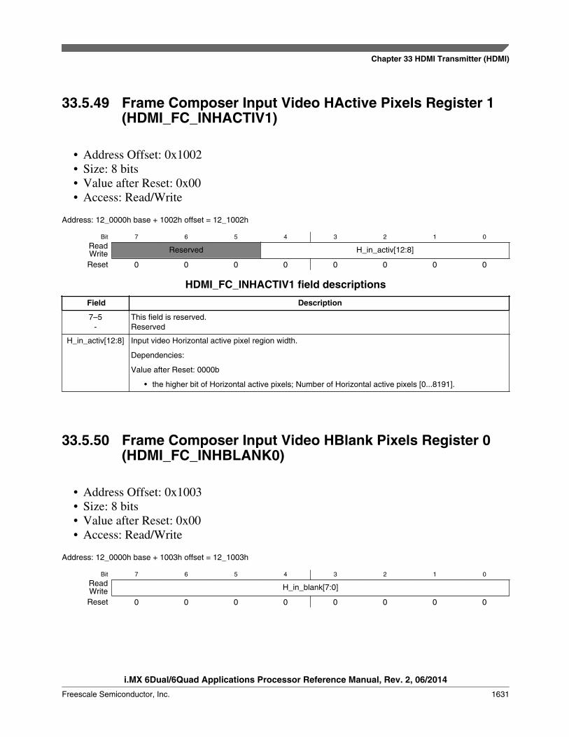
33.5.49 Frame Composer Input Video HActive Pixels Register 1(HDMI_FC_INHACTIV1)
• Address Offset: 0x1002• Size: 8 bits• Value after Reset: 0x00• Access: Read/Write
Address: 12_0000h base + 1002h offset = 12_1002h
Bit 7 6 5 4 3 2 1 0
Read Reserved H_in_activ[12:8]WriteReset 0 0 0 0 0 0 0 0
HDMI_FC_INHACTIV1 field descriptions
Field Description
7–5-
This field is reserved.Reserved
H_in_activ[12:8] Input video Horizontal active pixel region width.
Dependencies:
Value after Reset: 0000b
• the higher bit of Horizontal active pixels; Number of Horizontal active pixels [0...8191].
33.5.50 Frame Composer Input Video HBlank Pixels Register 0(HDMI_FC_INHBLANK0)
• Address Offset: 0x1003• Size: 8 bits• Value after Reset: 0x00• Access: Read/Write
Address: 12_0000h base + 1003h offset = 12_1003h
Bit 7 6 5 4 3 2 1 0
Read H_in_blank[7:0]WriteReset 0 0 0 0 0 0 0 0
Chapter 33 HDMI Transmitter (HDMI)
i.MX 6Dual/6Quad Applications Processor Reference Manual, Rev. 2, 06/2014
Freescale Semiconductor, Inc. 1631
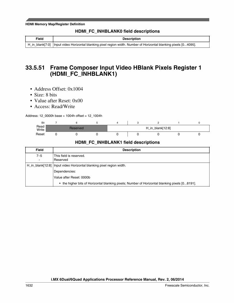
HDMI_FC_INHBLANK0 field descriptions
Field Description
H_in_blank[7:0] Input video Horizontal blanking pixel region width. Number of Horizontal blanking pixels [0...4095].
33.5.51 Frame Composer Input Video HBlank Pixels Register 1(HDMI_FC_INHBLANK1)
• Address Offset: 0x1004• Size: 8 bits• Value after Reset: 0x00• Access: Read/Write
Address: 12_0000h base + 1004h offset = 12_1004h
Bit 7 6 5 4 3 2 1 0
Read Reserved H_in_blank[12:8]WriteReset 0 0 0 0 0 0 0 0
HDMI_FC_INHBLANK1 field descriptions
Field Description
7–5-
This field is reserved.Reserved
H_in_blank[12:8] Input video Horizontal blanking pixel region width.
Dependencies:
Value after Reset: 0000b
• the higher bits of Horizontal blanking pixels; Number of Horizontal blanking pixels [0...8191].
HDMI Memory Map/Register Definition
i.MX 6Dual/6Quad Applications Processor Reference Manual, Rev. 2, 06/2014
1632 Freescale Semiconductor, Inc.

33.5.52 Frame Composer Input Video VActive Pixels Register 0(HDMI_FC_INVACTIV0)
• Address Offset: 0x1005• Size: 8 bits• Value after Reset: 0x00• Access: Read/Write
Address: 12_0000h base + 1005h offset = 12_1005h
Bit 7 6 5 4 3 2 1 0
Read V_in_activ[7:0]WriteReset 0 0 0 0 0 0 0 0
HDMI_FC_INVACTIV0 field descriptions
Field Description
V_in_activ[7:0] Input video Vertical active pixel region width. Number of Vertical active lines [0...4095].
33.5.53 Frame Composer Input Video VActive Pixels Register 1(HDMI_FC_INVACTIV1)
• Address Offset: 0x1006• Size: 8 bits• Value after Reset: 0x00• Access: Read/Write
Address: 12_0000h base + 1006h offset = 12_1006h
Bit 7 6 5 4 3 2 1 0
Read Reserved V_in_activ[12:8]WriteReset 0 0 0 0 0 0 0 0
HDMI_FC_INVACTIV1 field descriptions
Field Description
7–5-
This field is reserved.Reserved
V_in_activ[12:8] Input video Vertical active pixel region width.
Dependencies:
Value after Reset: 0000b
Table continues on the next page...
Chapter 33 HDMI Transmitter (HDMI)
i.MX 6Dual/6Quad Applications Processor Reference Manual, Rev. 2, 06/2014
Freescale Semiconductor, Inc. 1633
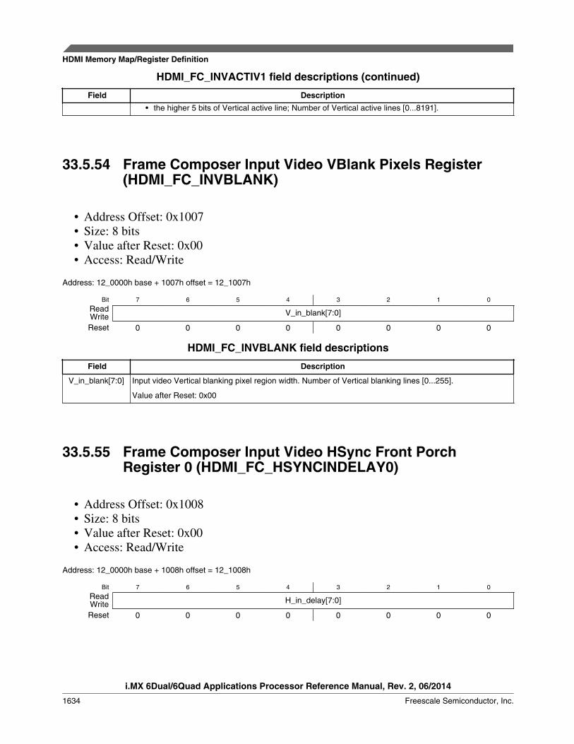
HDMI_FC_INVACTIV1 field descriptions (continued)
Field Description• the higher 5 bits of Vertical active line; Number of Vertical active lines [0...8191].
33.5.54 Frame Composer Input Video VBlank Pixels Register(HDMI_FC_INVBLANK)
• Address Offset: 0x1007• Size: 8 bits• Value after Reset: 0x00• Access: Read/Write
Address: 12_0000h base + 1007h offset = 12_1007h
Bit 7 6 5 4 3 2 1 0
Read V_in_blank[7:0]WriteReset 0 0 0 0 0 0 0 0
HDMI_FC_INVBLANK field descriptions
Field Description
V_in_blank[7:0] Input video Vertical blanking pixel region width. Number of Vertical blanking lines [0...255].
Value after Reset: 0x00
33.5.55 Frame Composer Input Video HSync Front PorchRegister 0 (HDMI_FC_HSYNCINDELAY0)
• Address Offset: 0x1008• Size: 8 bits• Value after Reset: 0x00• Access: Read/Write
Address: 12_0000h base + 1008h offset = 12_1008h
Bit 7 6 5 4 3 2 1 0
Read H_in_delay[7:0]WriteReset 0 0 0 0 0 0 0 0
HDMI Memory Map/Register Definition
i.MX 6Dual/6Quad Applications Processor Reference Manual, Rev. 2, 06/2014
1634 Freescale Semiconductor, Inc.
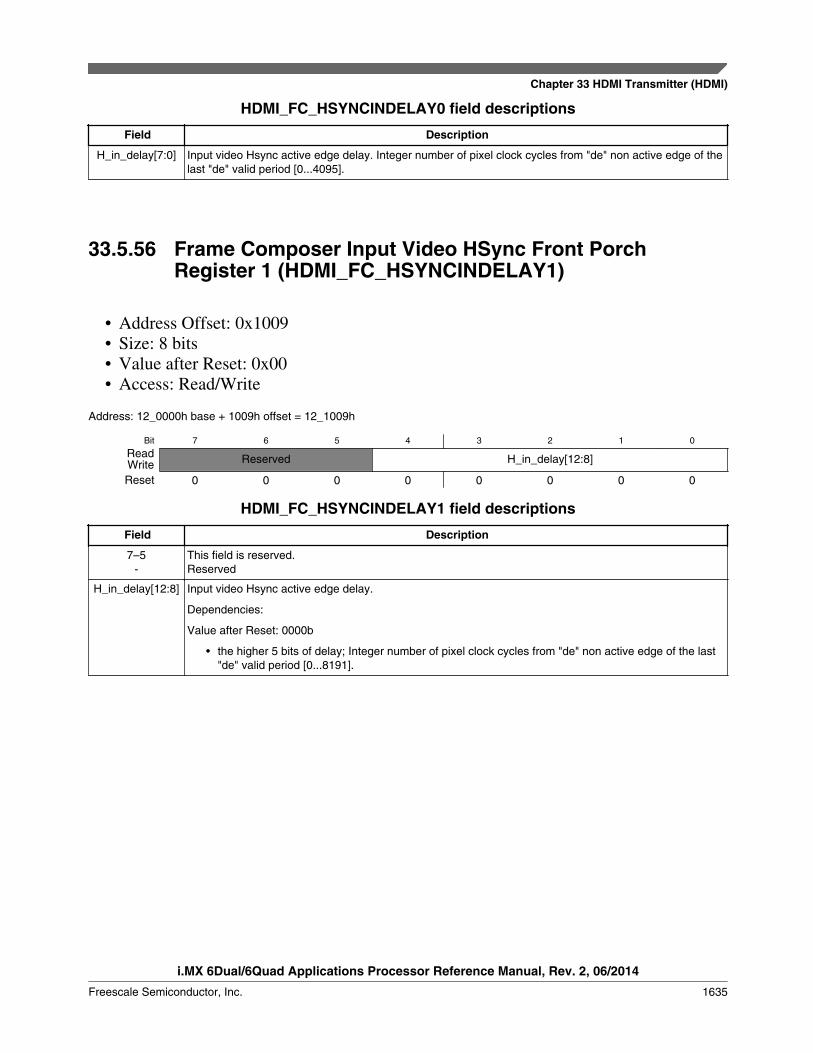
HDMI_FC_HSYNCINDELAY0 field descriptions
Field Description
H_in_delay[7:0] Input video Hsync active edge delay. Integer number of pixel clock cycles from "de" non active edge of thelast "de" valid period [0...4095].
33.5.56 Frame Composer Input Video HSync Front PorchRegister 1 (HDMI_FC_HSYNCINDELAY1)
• Address Offset: 0x1009• Size: 8 bits• Value after Reset: 0x00• Access: Read/Write
Address: 12_0000h base + 1009h offset = 12_1009h
Bit 7 6 5 4 3 2 1 0
Read Reserved H_in_delay[12:8]WriteReset 0 0 0 0 0 0 0 0
HDMI_FC_HSYNCINDELAY1 field descriptions
Field Description
7–5-
This field is reserved.Reserved
H_in_delay[12:8] Input video Hsync active edge delay.
Dependencies:
Value after Reset: 0000b
• the higher 5 bits of delay; Integer number of pixel clock cycles from "de" non active edge of the last"de" valid period [0...8191].
Chapter 33 HDMI Transmitter (HDMI)
i.MX 6Dual/6Quad Applications Processor Reference Manual, Rev. 2, 06/2014
Freescale Semiconductor, Inc. 1635
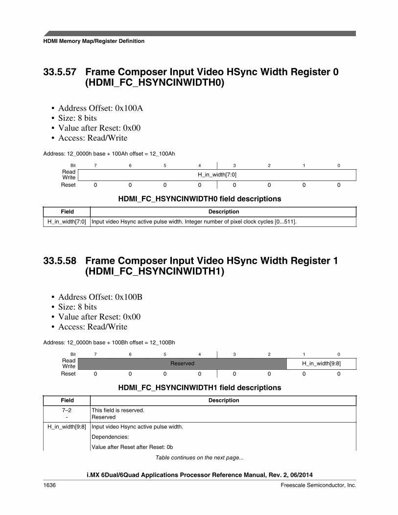
33.5.57 Frame Composer Input Video HSync Width Register 0(HDMI_FC_HSYNCINWIDTH0)
• Address Offset: 0x100A• Size: 8 bits• Value after Reset: 0x00• Access: Read/Write
Address: 12_0000h base + 100Ah offset = 12_100Ah
Bit 7 6 5 4 3 2 1 0
Read H_in_width[7:0]WriteReset 0 0 0 0 0 0 0 0
HDMI_FC_HSYNCINWIDTH0 field descriptions
Field Description
H_in_width[7:0] Input video Hsync active pulse width. Integer number of pixel clock cycles [0...511].
33.5.58 Frame Composer Input Video HSync Width Register 1(HDMI_FC_HSYNCINWIDTH1)
• Address Offset: 0x100B• Size: 8 bits• Value after Reset: 0x00• Access: Read/Write
Address: 12_0000h base + 100Bh offset = 12_100Bh
Bit 7 6 5 4 3 2 1 0
Read Reserved H_in_width[9:8]WriteReset 0 0 0 0 0 0 0 0
HDMI_FC_HSYNCINWIDTH1 field descriptions
Field Description
7–2-
This field is reserved.Reserved
H_in_width[9:8] Input video Hsync active pulse width.
Dependencies:
Value after Reset after Reset: 0b
Table continues on the next page...
HDMI Memory Map/Register Definition
i.MX 6Dual/6Quad Applications Processor Reference Manual, Rev. 2, 06/2014
1636 Freescale Semiconductor, Inc.
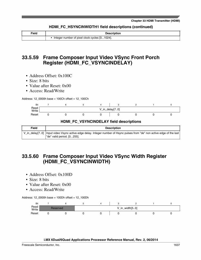
HDMI_FC_HSYNCINWIDTH1 field descriptions (continued)
Field Description• Integer number of pixel clock cycles [0...1024].
33.5.59 Frame Composer Input Video VSync Front PorchRegister (HDMI_FC_VSYNCINDELAY)
• Address Offset: 0x100C• Size: 8 bits• Value after Reset: 0x00• Access: Read/Write
Address: 12_0000h base + 100Ch offset = 12_100Ch
Bit 7 6 5 4 3 2 1 0
Read V_in_delay[7..0]WriteReset 0 0 0 0 0 0 0 0
HDMI_FC_VSYNCINDELAY field descriptions
Field Description
V_in_delay[7..0] Input video Vsync active edge delay. Integer number of Hsync pulses from "de" non active edge of the last"de" valid period. [0...255].
33.5.60 Frame Composer Input Video VSync Width Register(HDMI_FC_VSYNCINWIDTH)
• Address Offset: 0x100D• Size: 8 bits• Value after Reset: 0x00• Access: Read/Write
Address: 12_0000h base + 100Dh offset = 12_100Dh
Bit 7 6 5 4 3 2 1 0
Read Reserved V_in_width[5..0]WriteReset 0 0 0 0 0 0 0 0
Chapter 33 HDMI Transmitter (HDMI)
i.MX 6Dual/6Quad Applications Processor Reference Manual, Rev. 2, 06/2014
Freescale Semiconductor, Inc. 1637
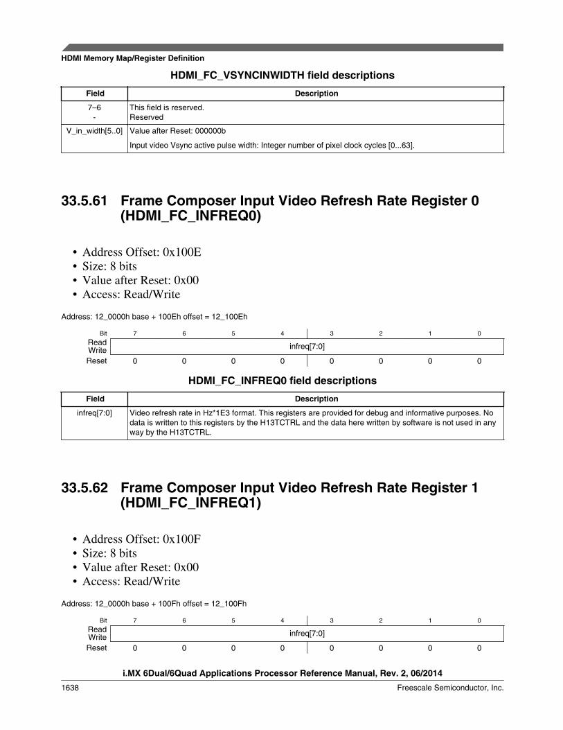
HDMI_FC_VSYNCINWIDTH field descriptions
Field Description
7–6-
This field is reserved.Reserved
V_in_width[5..0] Value after Reset: 000000b
Input video Vsync active pulse width: Integer number of pixel clock cycles [0...63].
33.5.61 Frame Composer Input Video Refresh Rate Register 0(HDMI_FC_INFREQ0)
• Address Offset: 0x100E• Size: 8 bits• Value after Reset: 0x00• Access: Read/Write
Address: 12_0000h base + 100Eh offset = 12_100Eh
Bit 7 6 5 4 3 2 1 0
Read infreq[7:0]WriteReset 0 0 0 0 0 0 0 0
HDMI_FC_INFREQ0 field descriptions
Field Description
infreq[7:0] Video refresh rate in Hz*1E3 format. This registers are provided for debug and informative purposes. Nodata is written to this registers by the H13TCTRL and the data here written by software is not used in anyway by the H13TCTRL.
33.5.62 Frame Composer Input Video Refresh Rate Register 1(HDMI_FC_INFREQ1)
• Address Offset: 0x100F• Size: 8 bits• Value after Reset: 0x00• Access: Read/Write
Address: 12_0000h base + 100Fh offset = 12_100Fh
Bit 7 6 5 4 3 2 1 0
Read infreq[7:0]WriteReset 0 0 0 0 0 0 0 0
HDMI Memory Map/Register Definition
i.MX 6Dual/6Quad Applications Processor Reference Manual, Rev. 2, 06/2014
1638 Freescale Semiconductor, Inc.

HDMI_FC_INFREQ1 field descriptions
Field Description
infreq[7:0] Video refresh rate in Hz*1E3 format. This registers are provided for debug and informative purposes. Nodata is written to this registers by the H13TCTRL and the data here written by software is not used in anyway by the H13TCTRL.
33.5.63 Frame Composer Input Video Refresh Rate Register 2(HDMI_FC_INFREQ2)
• Address Offset: 0x1010• Size: 8 bits• Value after Reset: 0x00• Access: Read/Write
Address: 12_0000h base + 1010h offset = 12_1010h
Bit 7 6 5 4 3 2 1 0
Read Reserved infreq[19:16]WriteReset 0 0 0 0 0 0 0 0
HDMI_FC_INFREQ2 field descriptions
Field Description
7–4-
This field is reserved.Reserved
infreq[19:16] Video refresh rate in Hz*1E3 format. This registers are provided for debug and informative purposes. Nodata is written to this registers by the H13TCTRL and the data here written by software is not used in anyway by the H13TCTRL.
Value after Reset: 0000b
Chapter 33 HDMI Transmitter (HDMI)
i.MX 6Dual/6Quad Applications Processor Reference Manual, Rev. 2, 06/2014
Freescale Semiconductor, Inc. 1639
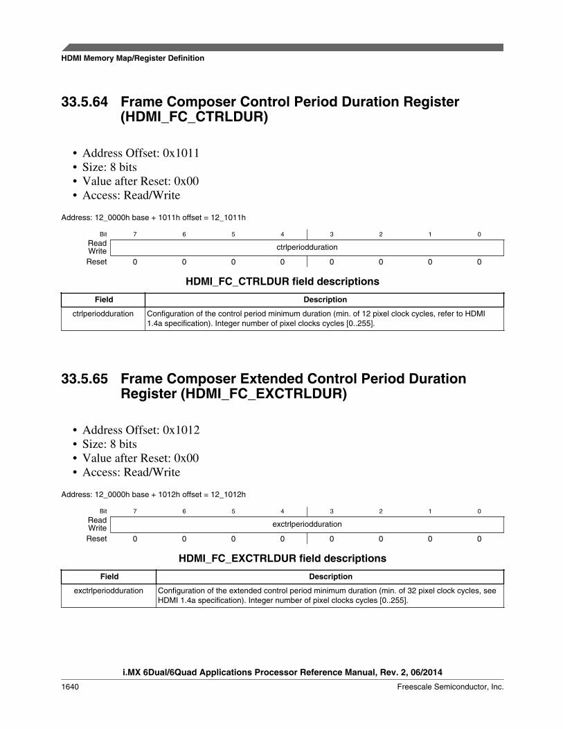
33.5.64 Frame Composer Control Period Duration Register(HDMI_FC_CTRLDUR)
• Address Offset: 0x1011• Size: 8 bits• Value after Reset: 0x00• Access: Read/Write
Address: 12_0000h base + 1011h offset = 12_1011h
Bit 7 6 5 4 3 2 1 0
Read ctrlperioddurationWriteReset 0 0 0 0 0 0 0 0
HDMI_FC_CTRLDUR field descriptions
Field Description
ctrlperiodduration Configuration of the control period minimum duration (min. of 12 pixel clock cycles, refer to HDMI1.4a specification). Integer number of pixel clocks cycles [0..255].
33.5.65 Frame Composer Extended Control Period DurationRegister (HDMI_FC_EXCTRLDUR)
• Address Offset: 0x1012• Size: 8 bits• Value after Reset: 0x00• Access: Read/Write
Address: 12_0000h base + 1012h offset = 12_1012h
Bit 7 6 5 4 3 2 1 0
Read exctrlperioddurationWriteReset 0 0 0 0 0 0 0 0
HDMI_FC_EXCTRLDUR field descriptions
Field Description
exctrlperiodduration Configuration of the extended control period minimum duration (min. of 32 pixel clock cycles, seeHDMI 1.4a specification). Integer number of pixel clocks cycles [0..255].
HDMI Memory Map/Register Definition
i.MX 6Dual/6Quad Applications Processor Reference Manual, Rev. 2, 06/2014
1640 Freescale Semiconductor, Inc.

33.5.66 Frame Composer Extended Control Period MaximumSpacing Register (HDMI_FC_EXCTRLSPAC)
• Address Offset: 0x1013• Size: 8 bits• Value after Reset: 0x00• Access: Read/Write
Address: 12_0000h base + 1013h offset = 12_1013h
Bit 7 6 5 4 3 2 1 0
Read exctrlperiodspacingWriteReset 0 0 0 0 0 0 0 0
HDMI_FC_EXCTRLSPAC field descriptions
Field Description
exctrlperiodspacing Configuration of the maximum spacing between consecutive extended control periods (max of50msec, see HDMI 1.4a specification):
generated spacing = (1/freq tmds clock)*256*256*extctrlperiodspacing
33.5.67 Frame Composer Channel 0 Non-Preamble Data Register(HDMI_FC_CH0PREAM)
• Address Offset: 0x1014• Size: 8 bits• Value after Reset: 0x00• Access: Read/Write
Address: 12_0000h base + 1014h offset = 12_1014h
Bit 7 6 5 4 3 2 1 0
Read ch0_preamble_filterWriteReset 0 0 0 0 0 0 0 0
HDMI_FC_CH0PREAM field descriptions
Field Description
ch0_preamble_filter
When in control mode, configures 8-bits that are going to fill the channel 0 data lines not used to transmitthe preamble (for more clarifications refer to HDMI 1.4a specification).
Chapter 33 HDMI Transmitter (HDMI)
i.MX 6Dual/6Quad Applications Processor Reference Manual, Rev. 2, 06/2014
Freescale Semiconductor, Inc. 1641

33.5.68 Frame Composer Channel 1 Non-Preamble Data Register(HDMI_FC_CH1PREAM)
• Address Offset: 0x1015• Size: 8 bits• Value after Reset: 0x00• Access: Read/Write
Address: 12_0000h base + 1015h offset = 12_1015h
Bit 7 6 5 4 3 2 1 0
Read Reserved ch1_preamble_filterWriteReset 0 0 0 0 0 0 0 0
HDMI_FC_CH1PREAM field descriptions
Field Description
7–6-
This field is reserved.Reserved
ch1_preamble_filter
When in control mode, configures 6-bits that are going to fill the channel 1 data lines not used to transmitthe preamble (for more clarifications refer to HDMI 1.4a specification).
33.5.69 Frame Composer Channel 2 Non-Preamble Data Register(HDMI_FC_CH2PREAM)
• Address Offset: 0x1016• Size: 8 bits• Value after Reset: 0x00• Access: Read/Write
Address: 12_0000h base + 1016h offset = 12_1016h
Bit 7 6 5 4 3 2 1 0
Read Reserved ch2_preamble_filterWriteReset 0 0 0 0 0 0 0 0
HDMI_FC_CH2PREAM field descriptions
Field Description
7–6-
This field is reserved.Reserved
Table continues on the next page...
HDMI Memory Map/Register Definition
i.MX 6Dual/6Quad Applications Processor Reference Manual, Rev. 2, 06/2014
1642 Freescale Semiconductor, Inc.

HDMI_FC_CH2PREAM field descriptions (continued)
Field Description
ch2_preamble_filter
When in control mode, configures 6-bits that are going to fill the channel 2 data lines not used to transmitthe preamble (for more clarifications, see HDMI 1.4a specification).
33.5.70 Frame Composer AVI Configuration Register 3(HDMI_FC_AVICONF3)
• Address Offset: 0x1017• Size: 8 bits• Value after Reset: 0x00• Access: Read/Write
configuration of Quantization range and IT content type.
Address: 12_0000h base + 1017h offset = 12_1017h
Bit 7 6 5 4 3 2 1 0
Read Reserved YQ1_YQ0_YCC CN1_CN0WriteReset 0 0 0 0 0 0 0 0
HDMI_FC_AVICONF3 field descriptions
Field Description
7–4-
This field is reserved.Reserved
3–2YQ1_YQ0_YCC
Quantization range according to CEA specification.
CN1_CN0 IT content type according to CEA specification
33.5.71 Frame Composer GCP Packet Configuration Register(HDMI_FC_GCP)
Configures the General Control Packet A/V mute indicators and the default phase.
• Address Offset: 0x1018• Size: 8 bits• Value after Reset: 0x00• Access: Read/Write
Chapter 33 HDMI Transmitter (HDMI)
i.MX 6Dual/6Quad Applications Processor Reference Manual, Rev. 2, 06/2014
Freescale Semiconductor, Inc. 1643
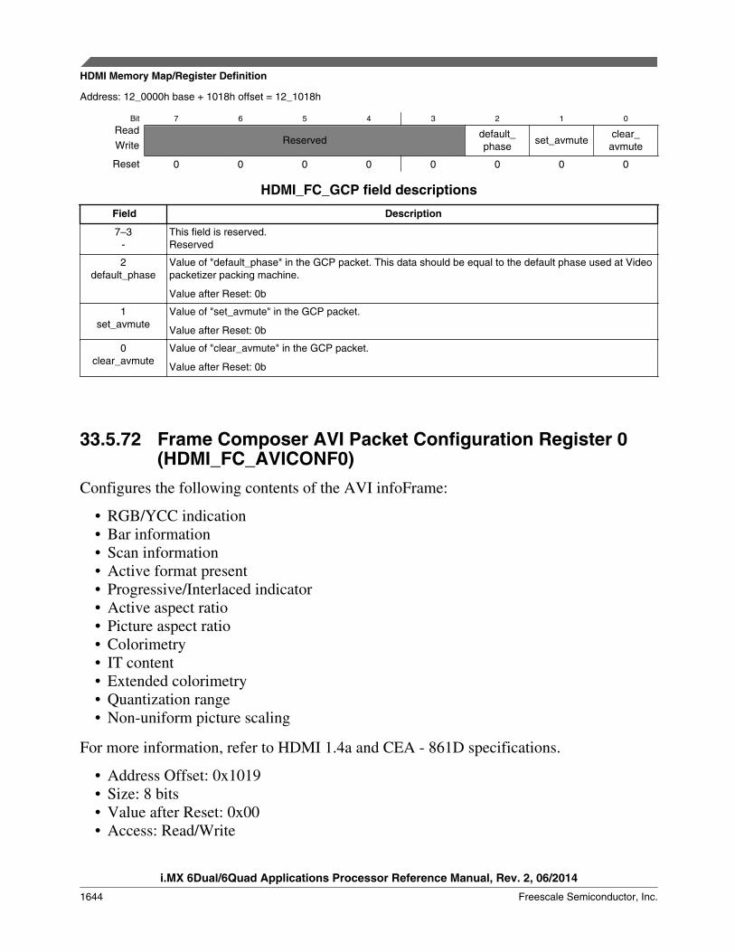
Address: 12_0000h base + 1018h offset = 12_1018h
Bit 7 6 5 4 3 2 1 0
ReadReserved
default_phase
set_avmuteclear_avmuteWrite
Reset 0 0 0 0 0 0 0 0
HDMI_FC_GCP field descriptions
Field Description
7–3-
This field is reserved.Reserved
2default_phase
Value of "default_phase" in the GCP packet. This data should be equal to the default phase used at Videopacketizer packing machine.
Value after Reset: 0b
1set_avmute
Value of "set_avmute" in the GCP packet.
Value after Reset: 0b
0clear_avmute
Value of "clear_avmute" in the GCP packet.
Value after Reset: 0b
33.5.72 Frame Composer AVI Packet Configuration Register 0(HDMI_FC_AVICONF0)
Configures the following contents of the AVI infoFrame:
• RGB/YCC indication• Bar information• Scan information• Active format present• Progressive/Interlaced indicator• Active aspect ratio• Picture aspect ratio• Colorimetry• IT content• Extended colorimetry• Quantization range• Non-uniform picture scaling
For more information, refer to HDMI 1.4a and CEA - 861D specifications.
• Address Offset: 0x1019• Size: 8 bits• Value after Reset: 0x00• Access: Read/Write
HDMI Memory Map/Register Definition
i.MX 6Dual/6Quad Applications Processor Reference Manual, Rev. 2, 06/2014
1644 Freescale Semiconductor, Inc.

Address: 12_0000h base + 1019h offset = 12_1019h
Bit 7 6 5 4 3 2 1 0
ReadFC_
AVICONF0_MISC
FC_AVICONF0_
ACTIVE_FORMAT
FC_AVICONF0_SCAN FC_AVICONF0_BARFC_AVICONF0_RGB_
YCCWrite
Reset 0 0 0 0 0 0 0 0
HDMI_FC_AVICONF0 field descriptions
Field Description
7FC_AVICONF0_
MISC
Frame composer AVI packet configuration bit
6FC_AVICONF0_
ACTIVE_FORMAT
Active format present
5–4FC_AVICONF0_
SCAN
Scan information
3–2FC_AVICONF0_
BAR
Bar information
FC_AVICONF0_RGB_YCC
RGB/YCC indication
Value after Reset: 0b
33.5.73 Frame Composer AVI Packet Configuration Register 1(HDMI_FC_AVICONF1)
• Address Offset: 0x101A• Size: 8 bits• Value after Reset: 0x00• Access: Read/Write
Address: 12_0000h base + 101Ah offset = 12_101Ah
Bit 7 6 5 4 3 2 1 0
ReadFC_AVICONF0_COLOR
FC_AVICONF1_PICTURE_AR
FC_AVICONF1_ACTIVE_ARWrite
Reset 0 0 0 0 0 0 0 0
Chapter 33 HDMI Transmitter (HDMI)
i.MX 6Dual/6Quad Applications Processor Reference Manual, Rev. 2, 06/2014
Freescale Semiconductor, Inc. 1645
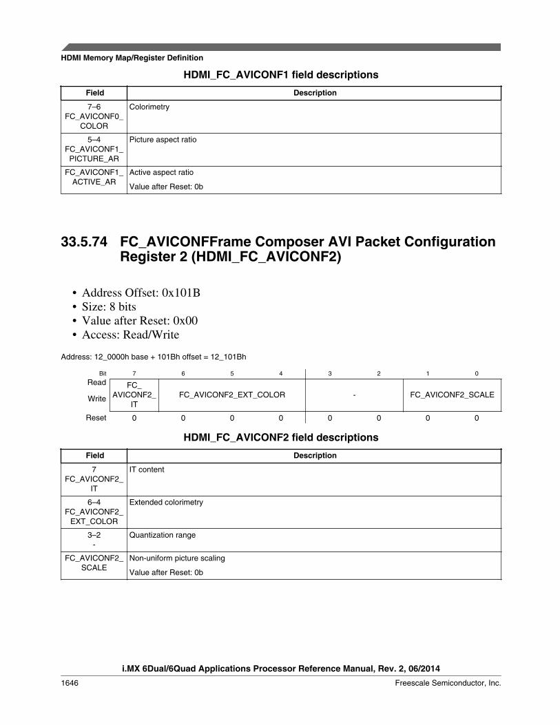
HDMI_FC_AVICONF1 field descriptions
Field Description
7–6FC_AVICONF0_
COLOR
Colorimetry
5–4FC_AVICONF1_
PICTURE_AR
Picture aspect ratio
FC_AVICONF1_ACTIVE_AR
Active aspect ratio
Value after Reset: 0b
33.5.74 FC_AVICONFFrame Composer AVI Packet ConfigurationRegister 2 (HDMI_FC_AVICONF2)
• Address Offset: 0x101B• Size: 8 bits• Value after Reset: 0x00• Access: Read/Write
Address: 12_0000h base + 101Bh offset = 12_101Bh
Bit 7 6 5 4 3 2 1 0
Read FC_AVICONF2_
ITFC_AVICONF2_EXT_COLOR - FC_AVICONF2_SCALEWrite
Reset 0 0 0 0 0 0 0 0
HDMI_FC_AVICONF2 field descriptions
Field Description
7FC_AVICONF2_
IT
IT content
6–4FC_AVICONF2_
EXT_COLOR
Extended colorimetry
3–2-
Quantization range
FC_AVICONF2_SCALE
Non-uniform picture scaling
Value after Reset: 0b
HDMI Memory Map/Register Definition
i.MX 6Dual/6Quad Applications Processor Reference Manual, Rev. 2, 06/2014
1646 Freescale Semiconductor, Inc.

33.5.75 Frame Composer AVI Packet VIC Register(HDMI_FC_AVIVID)
Configures the AVI infoFrame Video Identification code. For more information, refer tothe CEA-861-E specification.
• Address Offset: 0x101C• Size: 8 bits• Value after Reset: 0x00• Access: Read/Write
Address: 12_0000h base + 101Ch offset = 12_101Ch
Bit 7 6 5 4 3 2 1 0
Read FC_AVIVIDWriteReset 0 0 0 0 0 0 0 0
HDMI_FC_AVIVID field descriptions
Field Description
FC_AVIVID the AVI infoFrame Video Identification code.
33.5.76 Frame Composer AVI Packet End of Top Bar Register 0(HDMI_FC_AVIETB0)
These registers define the AVI infoFrame End of Top Bar value. For more information,refer to CEA-861-E specification.
• Address Offset: 0x101D• Size: 8 bits• Value after Reset: 0x00• Access: Read/Write
Address: 12_0000h base + 101Dh offset = 12_101Dh
Bit 7 6 5 4 3 2 1 0
Read -WriteReset 0 0 0 0 0 0 0 0
HDMI_FC_AVIETB0 field descriptions
Field Description
- Line number of end of top bar (lower 8 bits)
Chapter 33 HDMI Transmitter (HDMI)
i.MX 6Dual/6Quad Applications Processor Reference Manual, Rev. 2, 06/2014
Freescale Semiconductor, Inc. 1647

33.5.77 Frame Composer AVI Packet End of Top Bar Register 1(HDMI_FC_AVIETB1)
• Address Offset: 0x101E• Size: 8 bits• Value after Reset: 0x00• Access: Read/Write
Address: 12_0000h base + 101Eh offset = 12_101Eh
Bit 7 6 5 4 3 2 1 0
Read -WriteReset 0 0 0 0 0 0 0 0
HDMI_FC_AVIETB1 field descriptions
Field Description
- Line number of end of top bar (upper 8 bits)
33.5.78 Frame Composer AVI Packet Start of Bottom BarRegister 0 (HDMI_FC_AVISBB0)
These registers define the AVI infoFrame Start of Bottom Bar value. For moreinformation, refer to CEA-861D specification.
• Address Offset: 0x101F• Size: 8 bits• Value after Reset: 0x00• Access: Read/Write
Address: 12_0000h base + 101Fh offset = 12_101Fh
Bit 7 6 5 4 3 2 1 0
Read FC_AVISBB0WriteReset 0 0 0 0 0 0 0 0
HDMI_FC_AVISBB0 field descriptions
Field Description
FC_AVISBB0 Line number of Start of Bottom Bar (lower 8 bits)
HDMI Memory Map/Register Definition
i.MX 6Dual/6Quad Applications Processor Reference Manual, Rev. 2, 06/2014
1648 Freescale Semiconductor, Inc.

33.5.79 Frame Composer AVI Packet Start of Bottom BarRegister 1 (HDMI_FC_AVISBB1)
• Address Offset: 0x1020• Size: 8 bits• Value after Reset: 0x00• Access: Read/Write
Address: 12_0000h base + 1020h offset = 12_1020h
Bit 7 6 5 4 3 2 1 0
Read FC_AVISBB1WriteReset 0 0 0 0 0 0 0 0
HDMI_FC_AVISBB1 field descriptions
Field Description
FC_AVISBB1 Line number of Start of Bottom Bar (upper 8 bits)
33.5.80 Frame Composer AVI Packet End of Left Bar Register 0(HDMI_FC_AVIELB0)
These registers define the AVI infoFrame End of Left Bar value. For more information,refer to CEA-861D specification.
• Address Offset: 0x1021• Size: 8 bits• Value after Reset: 0x00• Access: Read/Write
Address: 12_0000h base + 1021h offset = 12_1021h
Bit 7 6 5 4 3 2 1 0
Read FC_AVIELB0WriteReset 0 0 0 0 0 0 0 0
HDMI_FC_AVIELB0 field descriptions
Field Description
FC_AVIELB0 Pixel number of end of left Bar (lower 8 bits)
Chapter 33 HDMI Transmitter (HDMI)
i.MX 6Dual/6Quad Applications Processor Reference Manual, Rev. 2, 06/2014
Freescale Semiconductor, Inc. 1649
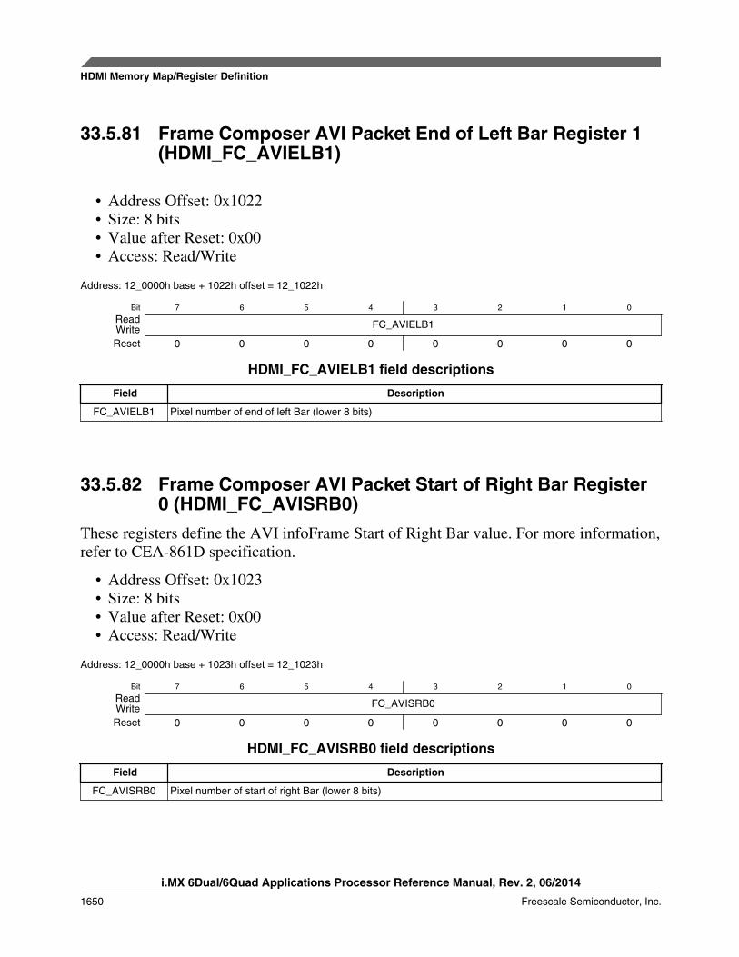
33.5.81 Frame Composer AVI Packet End of Left Bar Register 1(HDMI_FC_AVIELB1)
• Address Offset: 0x1022• Size: 8 bits• Value after Reset: 0x00• Access: Read/Write
Address: 12_0000h base + 1022h offset = 12_1022h
Bit 7 6 5 4 3 2 1 0
Read FC_AVIELB1WriteReset 0 0 0 0 0 0 0 0
HDMI_FC_AVIELB1 field descriptions
Field Description
FC_AVIELB1 Pixel number of end of left Bar (lower 8 bits)
33.5.82 Frame Composer AVI Packet Start of Right Bar Register0 (HDMI_FC_AVISRB0)
These registers define the AVI infoFrame Start of Right Bar value. For more information,refer to CEA-861D specification.
• Address Offset: 0x1023• Size: 8 bits• Value after Reset: 0x00• Access: Read/Write
Address: 12_0000h base + 1023h offset = 12_1023h
Bit 7 6 5 4 3 2 1 0
Read FC_AVISRB0WriteReset 0 0 0 0 0 0 0 0
HDMI_FC_AVISRB0 field descriptions
Field Description
FC_AVISRB0 Pixel number of start of right Bar (lower 8 bits)
HDMI Memory Map/Register Definition
i.MX 6Dual/6Quad Applications Processor Reference Manual, Rev. 2, 06/2014
1650 Freescale Semiconductor, Inc.
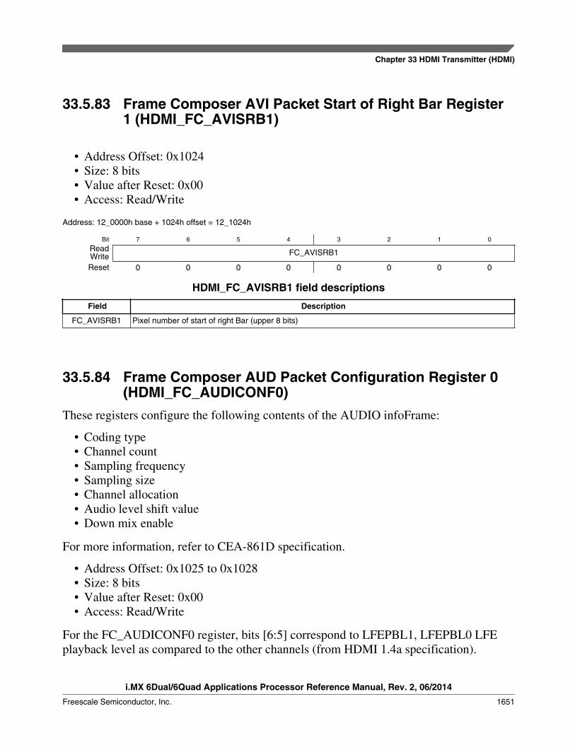
33.5.83 Frame Composer AVI Packet Start of Right Bar Register1 (HDMI_FC_AVISRB1)
• Address Offset: 0x1024• Size: 8 bits• Value after Reset: 0x00• Access: Read/Write
Address: 12_0000h base + 1024h offset = 12_1024h
Bit 7 6 5 4 3 2 1 0
Read FC_AVISRB1WriteReset 0 0 0 0 0 0 0 0
HDMI_FC_AVISRB1 field descriptions
Field Description
FC_AVISRB1 Pixel number of start of right Bar (upper 8 bits)
33.5.84 Frame Composer AUD Packet Configuration Register 0(HDMI_FC_AUDICONF0)
These registers configure the following contents of the AUDIO infoFrame:
• Coding type• Channel count• Sampling frequency• Sampling size• Channel allocation• Audio level shift value• Down mix enable
For more information, refer to CEA-861D specification.
• Address Offset: 0x1025 to 0x1028• Size: 8 bits• Value after Reset: 0x00• Access: Read/Write
For the FC_AUDICONF0 register, bits [6:5] correspond to LFEPBL1, LFEPBL0 LFEplayback level as compared to the other channels (from HDMI 1.4a specification).
Chapter 33 HDMI Transmitter (HDMI)
i.MX 6Dual/6Quad Applications Processor Reference Manual, Rev. 2, 06/2014
Freescale Semiconductor, Inc. 1651
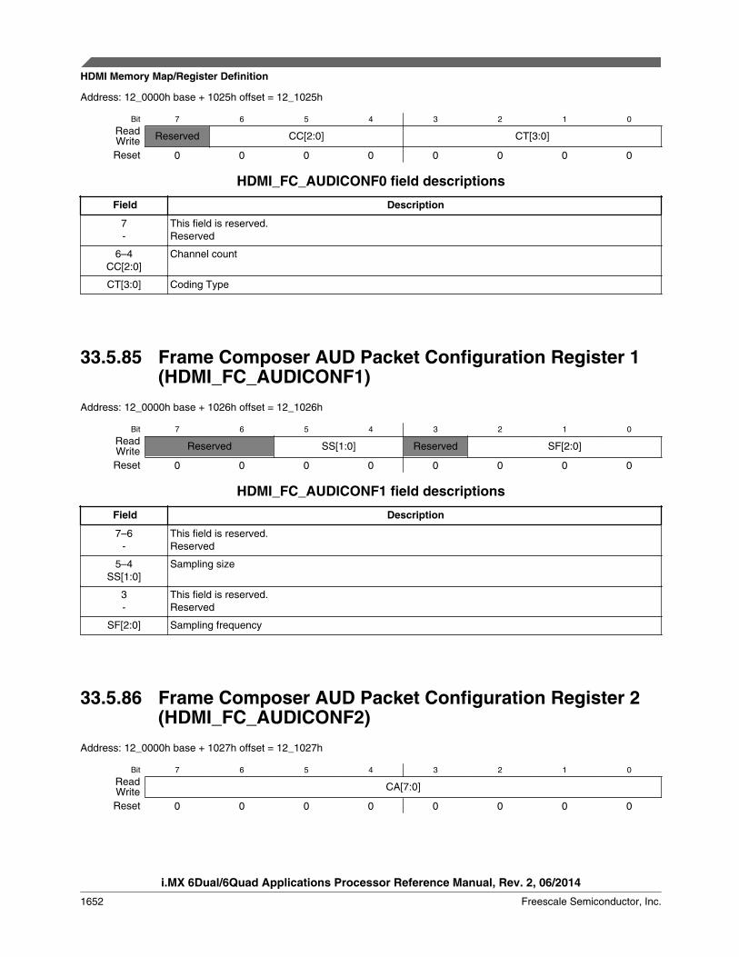
Address: 12_0000h base + 1025h offset = 12_1025h
Bit 7 6 5 4 3 2 1 0
Read Reserved CC[2:0] CT[3:0]WriteReset 0 0 0 0 0 0 0 0
HDMI_FC_AUDICONF0 field descriptions
Field Description
7-
This field is reserved.Reserved
6–4CC[2:0]
Channel count
CT[3:0] Coding Type
33.5.85 Frame Composer AUD Packet Configuration Register 1(HDMI_FC_AUDICONF1)
Address: 12_0000h base + 1026h offset = 12_1026h
Bit 7 6 5 4 3 2 1 0
Read Reserved SS[1:0] Reserved SF[2:0]WriteReset 0 0 0 0 0 0 0 0
HDMI_FC_AUDICONF1 field descriptions
Field Description
7–6-
This field is reserved.Reserved
5–4SS[1:0]
Sampling size
3-
This field is reserved.Reserved
SF[2:0] Sampling frequency
33.5.86 Frame Composer AUD Packet Configuration Register 2(HDMI_FC_AUDICONF2)
Address: 12_0000h base + 1027h offset = 12_1027h
Bit 7 6 5 4 3 2 1 0
Read CA[7:0]WriteReset 0 0 0 0 0 0 0 0
HDMI Memory Map/Register Definition
i.MX 6Dual/6Quad Applications Processor Reference Manual, Rev. 2, 06/2014
1652 Freescale Semiconductor, Inc.

HDMI_FC_AUDICONF2 field descriptions
Field Description
CA[7:0] Channel allocation
33.5.87 Frame Composer AUD Packet Configuration Register 3(HDMI_FC_AUDICONF3)
Address: 12_0000h base + 1028h offset = 12_1028h
Bit 7 6 5 4 3 2 1 0
Read Reserved LFEPBL[1:0] DM_INH LSV[3:0]WriteReset 0 0 0 0 0 0 0 0
HDMI_FC_AUDICONF3 field descriptions
Field Description
7-
This field is reserved.Reserved
6–5LFEPBL[1:0]
LFE playback information
4DM_INH
Down mix enable
LSV[3:0] Level shift value (for down mixing)
33.5.88 Frame Composer VSI Packet Data IEEE Register 0(HDMI_FC_VSDIEEEID0)
These registers configure the Vendor Specific infoFrame IEEE registration identifier. Formore information, refer to CEA-861D specification.
• Address Offset: 0x1029• Size: 8 bits• Value after Reset: 0x00• Access: Read/Write
Address: 12_0000h base + 1029h offset = 12_1029h
Bit 7 6 5 4 3 2 1 0
Read -WriteReset 0 0 0 0 0 0 0 0
Chapter 33 HDMI Transmitter (HDMI)
i.MX 6Dual/6Quad Applications Processor Reference Manual, Rev. 2, 06/2014
Freescale Semiconductor, Inc. 1653
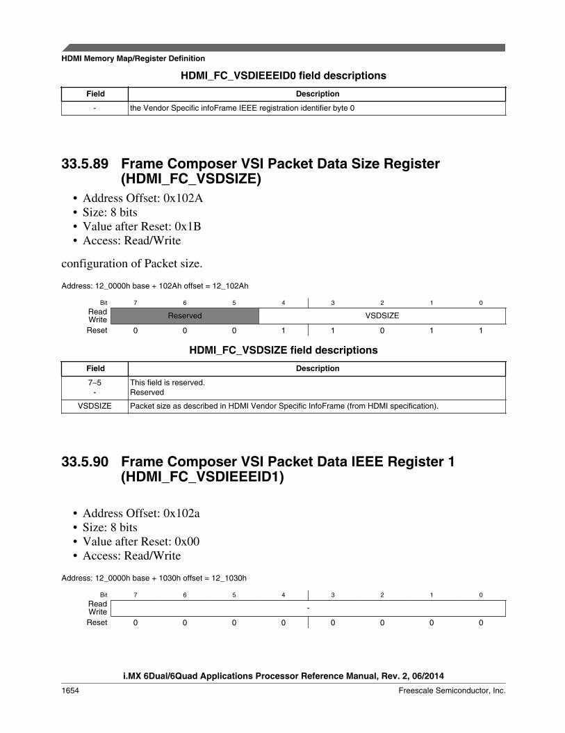
HDMI_FC_VSDIEEEID0 field descriptions
Field Description
- the Vendor Specific infoFrame IEEE registration identifier byte 0
33.5.89 Frame Composer VSI Packet Data Size Register(HDMI_FC_VSDSIZE)
• Address Offset: 0x102A• Size: 8 bits• Value after Reset: 0x1B• Access: Read/Write
configuration of Packet size.
Address: 12_0000h base + 102Ah offset = 12_102Ah
Bit 7 6 5 4 3 2 1 0
Read Reserved VSDSIZEWriteReset 0 0 0 1 1 0 1 1
HDMI_FC_VSDSIZE field descriptions
Field Description
7–5-
This field is reserved.Reserved
VSDSIZE Packet size as described in HDMI Vendor Specific InfoFrame (from HDMI specification).
33.5.90 Frame Composer VSI Packet Data IEEE Register 1(HDMI_FC_VSDIEEEID1)
• Address Offset: 0x102a• Size: 8 bits• Value after Reset: 0x00• Access: Read/Write
Address: 12_0000h base + 1030h offset = 12_1030h
Bit 7 6 5 4 3 2 1 0
Read -WriteReset 0 0 0 0 0 0 0 0
HDMI Memory Map/Register Definition
i.MX 6Dual/6Quad Applications Processor Reference Manual, Rev. 2, 06/2014
1654 Freescale Semiconductor, Inc.

HDMI_FC_VSDIEEEID1 field descriptions
Field Description
- the Vendor Specific infoFrame IEEE registration identifier byte 1
33.5.91 Frame Composer VSI Packet Data IEEE Register 2(HDMI_FC_VSDIEEEID2)
• Address Offset: 0x102b• Size: 8 bits• Value after Reset: 0x00• Access: Read/Write
Address: 12_0000h base + 1031h offset = 12_1031h
Bit 7 6 5 4 3 2 1 0
Read -WriteReset 0 0 0 0 0 0 0 0
HDMI_FC_VSDIEEEID2 field descriptions
Field Description
- the Vendor Specific infoFrame IEEE registration identifier byte 2
33.5.92 Frame Composer VSI Packet Data IEEE Register 0(HDMI_FC_VSDPAYLOAD0)
These registers configure the Vendor Specific infoFrame 24 bytes specific payload. Formore information, refer to CEA-861D specification.
• Address Offset: 0x1032• Size: 8 bits• Value after Reset: 0x00• Access: Read/Write
Address: 12_0000h base + 1032h offset = 12_1032h
Bit 7 6 5 4 3 2 1 0
Read -WriteReset 0 0 0 0 0 0 0 0
Chapter 33 HDMI Transmitter (HDMI)
i.MX 6Dual/6Quad Applications Processor Reference Manual, Rev. 2, 06/2014
Freescale Semiconductor, Inc. 1655
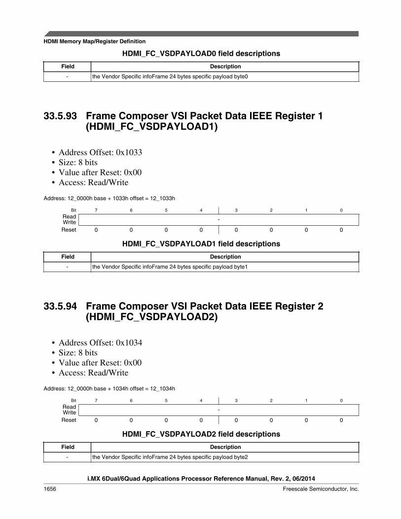
HDMI_FC_VSDPAYLOAD0 field descriptions
Field Description
- the Vendor Specific infoFrame 24 bytes specific payload byte0
33.5.93 Frame Composer VSI Packet Data IEEE Register 1(HDMI_FC_VSDPAYLOAD1)
• Address Offset: 0x1033• Size: 8 bits• Value after Reset: 0x00• Access: Read/Write
Address: 12_0000h base + 1033h offset = 12_1033h
Bit 7 6 5 4 3 2 1 0
Read -WriteReset 0 0 0 0 0 0 0 0
HDMI_FC_VSDPAYLOAD1 field descriptions
Field Description
- the Vendor Specific infoFrame 24 bytes specific payload byte1
33.5.94 Frame Composer VSI Packet Data IEEE Register 2(HDMI_FC_VSDPAYLOAD2)
• Address Offset: 0x1034• Size: 8 bits• Value after Reset: 0x00• Access: Read/Write
Address: 12_0000h base + 1034h offset = 12_1034h
Bit 7 6 5 4 3 2 1 0
Read -WriteReset 0 0 0 0 0 0 0 0
HDMI_FC_VSDPAYLOAD2 field descriptions
Field Description
- the Vendor Specific infoFrame 24 bytes specific payload byte2
HDMI Memory Map/Register Definition
i.MX 6Dual/6Quad Applications Processor Reference Manual, Rev. 2, 06/2014
1656 Freescale Semiconductor, Inc.

33.5.95 Frame Composer VSI Packet Data IEEE Register 3(HDMI_FC_VSDPAYLOAD3)
• Address Offset: 0x1035• Size: 8 bits• Value after Reset: 0x00• Access: Read/Write
Address: 12_0000h base + 1035h offset = 12_1035h
Bit 7 6 5 4 3 2 1 0
Read -WriteReset 0 0 0 0 0 0 0 0
HDMI_FC_VSDPAYLOAD3 field descriptions
Field Description
- the Vendor Specific infoFrame 24 bytes specific payload byte3
33.5.96 Frame Composer VSI Packet Data IEEE Register 4(HDMI_FC_VSDPAYLOAD4)
• Address Offset: 0x1036• Size: 8 bits• Value after Reset: 0x00• Access: Read/Write
Address: 12_0000h base + 1036h offset = 12_1036h
Bit 7 6 5 4 3 2 1 0
Read -WriteReset 0 0 0 0 0 0 0 0
HDMI_FC_VSDPAYLOAD4 field descriptions
Field Description
- the Vendor Specific infoFrame 24 bytes specific payload byte4
Chapter 33 HDMI Transmitter (HDMI)
i.MX 6Dual/6Quad Applications Processor Reference Manual, Rev. 2, 06/2014
Freescale Semiconductor, Inc. 1657

33.5.97 Frame Composer VSI Packet Data IEEE Register 5(HDMI_FC_VSDPAYLOAD5)
• Address Offset: 0x1037• Size: 8 bits• Value after Reset: 0x00• Access: Read/Write
Address: 12_0000h base + 1037h offset = 12_1037h
Bit 7 6 5 4 3 2 1 0
Read -WriteReset 0 0 0 0 0 0 0 0
HDMI_FC_VSDPAYLOAD5 field descriptions
Field Description
- the Vendor Specific infoFrame 24 bytes specific payload byte5
33.5.98 Frame Composer VSI Packet Data IEEE Register 6(HDMI_FC_VSDPAYLOAD6)
• Address Offset: 0x1038• Size: 8 bits• Value after Reset: 0x00• Access: Read/Write
Address: 12_0000h base + 1038h offset = 12_1038h
Bit 7 6 5 4 3 2 1 0
Read -WriteReset 0 0 0 0 0 0 0 0
HDMI_FC_VSDPAYLOAD6 field descriptions
Field Description
- the Vendor Specific infoFrame 24 bytes specific payload byte6
HDMI Memory Map/Register Definition
i.MX 6Dual/6Quad Applications Processor Reference Manual, Rev. 2, 06/2014
1658 Freescale Semiconductor, Inc.
33.5.99 Frame Composer VSI Packet Data IEEE Register 7(HDMI_FC_VSDPAYLOAD7)
• Address Offset: 0x1039• Size: 8 bits• Value after Reset: 0x00• Access: Read/Write
Address: 12_0000h base + 1039h offset = 12_1039h
Bit 7 6 5 4 3 2 1 0
Read -WriteReset 0 0 0 0 0 0 0 0
HDMI_FC_VSDPAYLOAD7 field descriptions
Field Description
- the Vendor Specific infoFrame 24 bytes specific payload byte7
33.5.100 Frame Composer VSI Packet Data IEEE Register 8(HDMI_FC_VSDPAYLOAD8)
• Address Offset: 0x103a• Size: 8 bits• Value after Reset: 0x00• Access: Read/Write
Address: 12_0000h base + 103Ah offset = 12_103Ah
Bit 7 6 5 4 3 2 1 0
Read -WriteReset 0 0 0 0 0 0 0 0
HDMI_FC_VSDPAYLOAD8 field descriptions
Field Description
- the Vendor Specific infoFrame 24 bytes specific payload byte8
Chapter 33 HDMI Transmitter (HDMI)
i.MX 6Dual/6Quad Applications Processor Reference Manual, Rev. 2, 06/2014
Freescale Semiconductor, Inc. 1659

33.5.101 Frame Composer VSI Packet Data IEEE Register 9(HDMI_FC_VSDPAYLOAD9)
• Address Offset: 0x103b• Size: 8 bits• Value after Reset: 0x00• Access: Read/Write
Address: 12_0000h base + 103Bh offset = 12_103Bh
Bit 7 6 5 4 3 2 1 0
Read -WriteReset 0 0 0 0 0 0 0 0
HDMI_FC_VSDPAYLOAD9 field descriptions
Field Description
- the Vendor Specific infoFrame 24 bytes specific payload byte9
33.5.102 Frame Composer VSI Packet Data IEEE Register 10(HDMI_FC_VSDPAYLOAD10)
• Address Offset: 0x103c• Size: 8 bits• Value after Reset: 0x00• Access: Read/Write
Address: 12_0000h base + 103Ch offset = 12_103Ch
Bit 7 6 5 4 3 2 1 0
Read -WriteReset 0 0 0 0 0 0 0 0
HDMI_FC_VSDPAYLOAD10 field descriptions
Field Description
- the Vendor Specific infoFrame 24 bytes specific payload byte10
HDMI Memory Map/Register Definition
i.MX 6Dual/6Quad Applications Processor Reference Manual, Rev. 2, 06/2014
1660 Freescale Semiconductor, Inc.

33.5.103 Frame Composer VSI Packet Data IEEE Register 11(HDMI_FC_VSDPAYLOAD11)
• Address Offset: 0x103d• Size: 8 bits• Value after Reset: 0x00• Access: Read/Write
Address: 12_0000h base + 103Dh offset = 12_103Dh
Bit 7 6 5 4 3 2 1 0
Read -WriteReset 0 0 0 0 0 0 0 0
HDMI_FC_VSDPAYLOAD11 field descriptions
Field Description
- the Vendor Specific infoFrame 24 bytes specific payload byte11
33.5.104 Frame Composer VSI Packet Data IEEE Register 12(HDMI_FC_VSDPAYLOAD12)
• Address Offset: 0x103e• Size: 8 bits• Value after Reset: 0x00• Access: Read/Write
Address: 12_0000h base + 103Eh offset = 12_103Eh
Bit 7 6 5 4 3 2 1 0
Read -WriteReset 0 0 0 0 0 0 0 0
HDMI_FC_VSDPAYLOAD12 field descriptions
Field Description
- the Vendor Specific infoFrame 24 bytes specific payload byte12
Chapter 33 HDMI Transmitter (HDMI)
i.MX 6Dual/6Quad Applications Processor Reference Manual, Rev. 2, 06/2014
Freescale Semiconductor, Inc. 1661

33.5.105 Frame Composer VSI Packet Data IEEE Register 13(HDMI_FC_VSDPAYLOAD13)
• Address Offset: 0x103f• Size: 8 bits• Value after Reset: 0x00• Access: Read/Write
Address: 12_0000h base + 103Fh offset = 12_103Fh
Bit 7 6 5 4 3 2 1 0
Read -WriteReset 0 0 0 0 0 0 0 0
HDMI_FC_VSDPAYLOAD13 field descriptions
Field Description
- the Vendor Specific infoFrame 24 bytes specific payload byte13
33.5.106 Frame Composer VSI Packet Data IEEE Register 14(HDMI_FC_VSDPAYLOAD14)
• Address Offset: 0x1040• Size: 8 bits• Value after Reset: 0x00• Access: Read/Write
Address: 12_0000h base + 1040h offset = 12_1040h
Bit 7 6 5 4 3 2 1 0
Read -WriteReset 0 0 0 0 0 0 0 0
HDMI_FC_VSDPAYLOAD14 field descriptions
Field Description
- the Vendor Specific infoFrame 24 bytes specific payload byte14
HDMI Memory Map/Register Definition
i.MX 6Dual/6Quad Applications Processor Reference Manual, Rev. 2, 06/2014
1662 Freescale Semiconductor, Inc.
33.5.107 Frame Composer VSI Packet Data IEEE Register 15(HDMI_FC_VSDPAYLOAD15)
• Address Offset: 0x1041• Size: 8 bits• Value after Reset: 0x00• Access: Read/Write
Address: 12_0000h base + 1041h offset = 12_1041h
Bit 7 6 5 4 3 2 1 0
Read -WriteReset 0 0 0 0 0 0 0 0
HDMI_FC_VSDPAYLOAD15 field descriptions
Field Description
- the Vendor Specific infoFrame 24 bytes specific payload byte15
33.5.108 Frame Composer VSI Packet Data IEEE Register 16(HDMI_FC_VSDPAYLOAD16)
• Address Offset: 0x1042• Size: 8 bits• Value after Reset: 0x00• Access: Read/Write
Address: 12_0000h base + 1042h offset = 12_1042h
Bit 7 6 5 4 3 2 1 0
Read -WriteReset 0 0 0 0 0 0 0 0
HDMI_FC_VSDPAYLOAD16 field descriptions
Field Description
- the Vendor Specific infoFrame 24 bytes specific payload byte16
Chapter 33 HDMI Transmitter (HDMI)
i.MX 6Dual/6Quad Applications Processor Reference Manual, Rev. 2, 06/2014
Freescale Semiconductor, Inc. 1663

33.5.109 Frame Composer VSI Packet Data IEEE Register 17(HDMI_FC_VSDPAYLOAD17)
• Address Offset: 0x1043• Size: 8 bits• Value after Reset: 0x00• Access: Read/Write
Address: 12_0000h base + 1043h offset = 12_1043h
Bit 7 6 5 4 3 2 1 0
Read -WriteReset 0 0 0 0 0 0 0 0
HDMI_FC_VSDPAYLOAD17 field descriptions
Field Description
- the Vendor Specific infoFrame 24 bytes specific payload byte17
33.5.110 Frame Composer VSI Packet Data IEEE Register 18(HDMI_FC_VSDPAYLOAD18)
• Address Offset: 0x1044• Size: 8 bits• Value after Reset: 0x00• Access: Read/Write
Address: 12_0000h base + 1044h offset = 12_1044h
Bit 7 6 5 4 3 2 1 0
Read -WriteReset 0 0 0 0 0 0 0 0
HDMI_FC_VSDPAYLOAD18 field descriptions
Field Description
- the Vendor Specific infoFrame 24 bytes specific payload byte18
HDMI Memory Map/Register Definition
i.MX 6Dual/6Quad Applications Processor Reference Manual, Rev. 2, 06/2014
1664 Freescale Semiconductor, Inc.
33.5.111 Frame Composer VSI Packet Data IEEE Register 19(HDMI_FC_VSDPAYLOAD19)
• Address Offset: 0x1045• Size: 8 bits• Value after Reset: 0x00• Access: Read/Write
Address: 12_0000h base + 1045h offset = 12_1045h
Bit 7 6 5 4 3 2 1 0
Read -WriteReset 0 0 0 0 0 0 0 0
HDMI_FC_VSDPAYLOAD19 field descriptions
Field Description
- the Vendor Specific infoFrame 24 bytes specific payload byte19
33.5.112 Frame Composer VSI Packet Data IEEE Register 20(HDMI_FC_VSDPAYLOAD20)
• Address Offset: 0x1046• Size: 8 bits• Value after Reset: 0x00• Access: Read/Write
Address: 12_0000h base + 1046h offset = 12_1046h
Bit 7 6 5 4 3 2 1 0
Read -WriteReset 0 0 0 0 0 0 0 0
HDMI_FC_VSDPAYLOAD20 field descriptions
Field Description
- the Vendor Specific infoFrame 24 bytes specific payload byte20
Chapter 33 HDMI Transmitter (HDMI)
i.MX 6Dual/6Quad Applications Processor Reference Manual, Rev. 2, 06/2014
Freescale Semiconductor, Inc. 1665

33.5.113 Frame Composer VSI Packet Data IEEE Register 21(HDMI_FC_VSDPAYLOAD21)
• Address Offset: 0x1047• Size: 8 bits• Value after Reset: 0x00• Access: Read/Write
Address: 12_0000h base + 1047h offset = 12_1047h
Bit 7 6 5 4 3 2 1 0
Read -WriteReset 0 0 0 0 0 0 0 0
HDMI_FC_VSDPAYLOAD21 field descriptions
Field Description
- the Vendor Specific infoFrame 24 bytes specific payload byte21
33.5.114 Frame Composer VSI Packet Data IEEE Register 22(HDMI_FC_VSDPAYLOAD22)
• Address Offset: 0x1048• Size: 8 bits• Value after Reset: 0x00• Access: Read/Write
Address: 12_0000h base + 1048h offset = 12_1048h
Bit 7 6 5 4 3 2 1 0
Read -WriteReset 0 0 0 0 0 0 0 0
HDMI_FC_VSDPAYLOAD22 field descriptions
Field Description
- the Vendor Specific infoFrame 24 bytes specific payload byte22
HDMI Memory Map/Register Definition
i.MX 6Dual/6Quad Applications Processor Reference Manual, Rev. 2, 06/2014
1666 Freescale Semiconductor, Inc.

33.5.115 Frame Composer VSI Packet Data IEEE Register 23(HDMI_FC_VSDPAYLOAD23)
• Address Offset: 0x1049• Size: 8 bits• Value after Reset: 0x00• Access: Read/Write
Address: 12_0000h base + 1049h offset = 12_1049h
Bit 7 6 5 4 3 2 1 0
Read -WriteReset 0 0 0 0 0 0 0 0
HDMI_FC_VSDPAYLOAD23 field descriptions
Field Description
- the Vendor Specific infoFrame 24 bytes specific payload byte23
33.5.116 Frame Composer SPD Packet Data Vendor NameRegister 0 (HDMI_FC_SPDVENDORNAME0)
These registers configure the Source Product Descriptor infoFrame 8 bytes Vendor name.For more information, refer to CEA-861D specification.
• Address Offset: 0x104A to 0x1051• Size: 8 bits• Value after Reset: 0x00• Access: Read/Write
Address: 12_0000h base + 104Ah offset = 12_104Ah
Bit 7 6 5 4 3 2 1 0
Read vendor_nameWriteReset 0 0 0 0 0 0 0 0
HDMI_FC_SPDVENDORNAME0 field descriptions
Field Description
vendor_name Vendor name
Chapter 33 HDMI Transmitter (HDMI)
i.MX 6Dual/6Quad Applications Processor Reference Manual, Rev. 2, 06/2014
Freescale Semiconductor, Inc. 1667

33.5.117 Frame Composer SPD Packet Data Product NameRegister 0 (HDMI_FC_SPDPRODUCTNAME0)
These registers configure the Source Product Descriptor infoFrame 16 bytes Productname. For more information, refer to CEA-861D specification.
• Address Offset: 0x1052 to 0x1061• Size: 8 bits• Value after Reset: 0x00• Access: Read/Write
Address: 12_0000h base + 1052h offset = 12_1052h
Bit 7 6 5 4 3 2 1 0
Read product_nameWriteReset 0 0 0 0 0 0 0 0
HDMI_FC_SPDPRODUCTNAME0 field descriptions
Field Description
product_name Product name
33.5.118 Frame Composer SPD Packet Data Source ProductDescriptor Register (HDMI_FC_SPDDEVICEINF)
This register configures Source Product Descriptor infoFrame description device field.For more information, refer to CEA-861D specification.
• Address Offset: 0x1062• Size: 8 bits• Value after Reset: 0x00• Access: Read/Write
Address: 12_0000h base + 1062h offset = 12_1062h
Bit 7 6 5 4 3 2 1 0
Read product_descriptorWriteReset 0 0 0 0 0 0 0 0
HDMI_FC_SPDDEVICEINF field descriptions
Field Description
product_descriptor
Product descriptor
HDMI Memory Map/Register Definition
i.MX 6Dual/6Quad Applications Processor Reference Manual, Rev. 2, 06/2014
1668 Freescale Semiconductor, Inc.
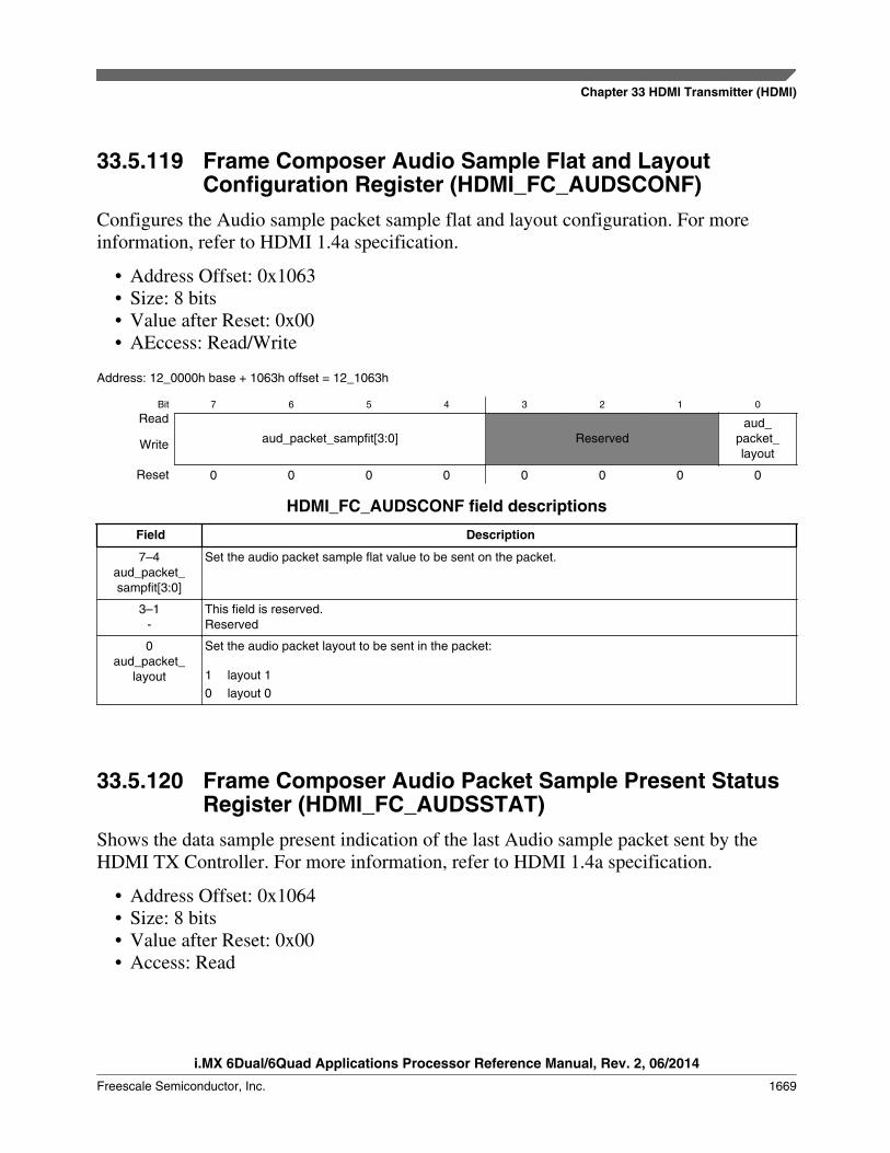
33.5.119 Frame Composer Audio Sample Flat and LayoutConfiguration Register (HDMI_FC_AUDSCONF)
Configures the Audio sample packet sample flat and layout configuration. For moreinformation, refer to HDMI 1.4a specification.
• Address Offset: 0x1063• Size: 8 bits• Value after Reset: 0x00• AEccess: Read/Write
Address: 12_0000h base + 1063h offset = 12_1063h
Bit 7 6 5 4 3 2 1 0
Read
aud_packet_sampfit[3:0] Reservedaud_
packet_layout
Write
Reset 0 0 0 0 0 0 0 0
HDMI_FC_AUDSCONF field descriptions
Field Description
7–4aud_packet_sampfit[3:0]
Set the audio packet sample flat value to be sent on the packet.
3–1-
This field is reserved.Reserved
0aud_packet_
layout
Set the audio packet layout to be sent in the packet:
1 layout 10 layout 0
33.5.120 Frame Composer Audio Packet Sample Present StatusRegister (HDMI_FC_AUDSSTAT)
Shows the data sample present indication of the last Audio sample packet sent by theHDMI TX Controller. For more information, refer to HDMI 1.4a specification.
• Address Offset: 0x1064• Size: 8 bits• Value after Reset: 0x00• Access: Read
Chapter 33 HDMI Transmitter (HDMI)
i.MX 6Dual/6Quad Applications Processor Reference Manual, Rev. 2, 06/2014
Freescale Semiconductor, Inc. 1669
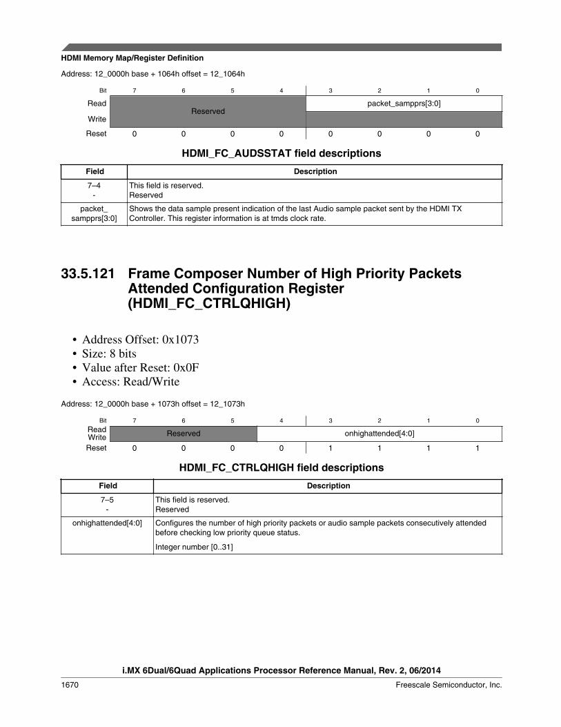
Address: 12_0000h base + 1064h offset = 12_1064h
Bit 7 6 5 4 3 2 1 0
ReadReserved
packet_sampprs[3:0]
Write
Reset 0 0 0 0 0 0 0 0
HDMI_FC_AUDSSTAT field descriptions
Field Description
7–4-
This field is reserved.Reserved
packet_sampprs[3:0]
Shows the data sample present indication of the last Audio sample packet sent by the HDMI TXController. This register information is at tmds clock rate.
33.5.121 Frame Composer Number of High Priority PacketsAttended Configuration Register(HDMI_FC_CTRLQHIGH)
• Address Offset: 0x1073• Size: 8 bits• Value after Reset: 0x0F• Access: Read/Write
Address: 12_0000h base + 1073h offset = 12_1073h
Bit 7 6 5 4 3 2 1 0
Read Reserved onhighattended[4:0]WriteReset 0 0 0 0 1 1 1 1
HDMI_FC_CTRLQHIGH field descriptions
Field Description
7–5-
This field is reserved.Reserved
onhighattended[4:0] Configures the number of high priority packets or audio sample packets consecutively attendedbefore checking low priority queue status.
Integer number [0..31]
HDMI Memory Map/Register Definition
i.MX 6Dual/6Quad Applications Processor Reference Manual, Rev. 2, 06/2014
1670 Freescale Semiconductor, Inc.

33.5.122 Frame Composer Number of Low Priority PacketsAttended Configuration Register(HDMI_FC_CTRLQLOW)
• Address Offset: 0x1074• Size: 8 bits• Value after Reset: 0x03• Access: Read/Write
Address: 12_0000h base + 1074h offset = 12_1074h
Bit 7 6 5 4 3 2 1 0
Read Reserved onlowattended[4:0]WriteReset 0 0 0 0 0 0 1 1
HDMI_FC_CTRLQLOW field descriptions
Field Description
7–5-
This field is reserved.Reserved
onlowattended[4:0] Configures the number of low priority packets or null packets consecutively attended beforechecking high priority queue status or audio sample availability.
Integer number [0..31]
33.5.123 Frame Composer ACP Packet Type ConfigurationRegister 0 (HDMI_FC_ACP0)
Configures the following contents of the ACP packet. For more information, refer to theHDMI 1.4 specification.
• Address Offset: 0x1075• Size: 8 bits• Value after Reset: 0x00• Access: Read/Write
Address: 12_0000h base + 1075h offset = 12_1075h
Bit 7 6 5 4 3 2 1 0
Read acptype[7:0]WriteReset 0 0 0 0 0 0 0 0
Chapter 33 HDMI Transmitter (HDMI)
i.MX 6Dual/6Quad Applications Processor Reference Manual, Rev. 2, 06/2014
Freescale Semiconductor, Inc. 1671

HDMI_FC_ACP0 field descriptions
Field Description
acptype[7:0] Configures the ACP packet type.
33.5.124 Frame Composer ACP Packet Type ConfigurationRegister 1 (HDMI_FC_ACP1)
Configures the following contents of the Audio Content Packet (ACP) body:
• Address Offset: 0x1091 to 0x1082• Size: 8 bits• Value after Reset: 0x00• Access: Read/Write
Address: 12_0000h base + 1091h offset = 12_1091h
Bit 7 6 5 4 3 2 1 0
Read Audio_contentpacketWriteReset 0 0 0 0 0 0 0 0
HDMI_FC_ACP1 field descriptions
Field Description
Audio_contentpacket
Audio content packet
33.5.125 FC_ISCR1_Frame Composer Packet Status, Valid, andContinue Configuration Register (HDMI_FC_ISCR1_0)
Configures the following contents of the ISRC1 packet:
• Address Offset: 0x1092• Size: 8 bits• Value after Reset: 0x00• Access: Read/Write
For more information, see the HDMI 1.4 specification.
Address: 12_0000h base + 1092h offset = 12_1092h
Bit 7 6 5 4 3 2 1 0
Read Reserved isrc_status[2:0] isrc_valid isrc_contWriteReset 0 0 0 0 0 0 0 0
HDMI Memory Map/Register Definition
i.MX 6Dual/6Quad Applications Processor Reference Manual, Rev. 2, 06/2014
1672 Freescale Semiconductor, Inc.

HDMI_FC_ISCR1_0 field descriptions
Field Description
7–5-
This field is reserved.Reserved
4–2isrc_status[2:0]
Status of ISRC1.
1isrc_valid
Valid of ISRC1.
0isrc_cont
Indication of ISRC2.
33.5.126 Frame Composer ISCR1 Packet Body Register 1(HDMI_FC_ISCR1_1)
Configures the following contents of the ISRC1 packet:
• ISRC1 packet body• Address Offset: 0x10A2 to 0x1093• Size: 8 bits• Value after Reset: 0x00• Access: Read/Write
For more information, see the HDMI 1.4 specification.
Address: 12_0000h base + 1093h offset = 12_1093h
Bit 7 6 5 4 3 2 1 0
Read isrc1WriteReset 0 0 0 0 0 0 0 0
HDMI_FC_ISCR1_1 field descriptions
Field Description
isrc1 Configures the contents of the ISRC1 packet:
33.5.127 Frame Composer ISCR2 Packet Body Register 0(HDMI_FC_ISCR2_0)
Configures the following contents of the ISRC2 packet:
• ISRC2 packet body• Address Offset: 0x10B2 to 0x10A3• Size: 8 bits
Chapter 33 HDMI Transmitter (HDMI)
i.MX 6Dual/6Quad Applications Processor Reference Manual, Rev. 2, 06/2014
Freescale Semiconductor, Inc. 1673
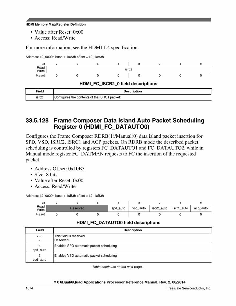
• Value after Reset: 0x00• Access: Read/Write
For more information, see the HDMI 1.4 specification.
Address: 12_0000h base + 10A3h offset = 12_10A3h
Bit 7 6 5 4 3 2 1 0
Read isrc2WriteReset 0 0 0 0 0 0 0 0
HDMI_FC_ISCR2_0 field descriptions
Field Description
isrc2 Configures the contents of the ISRC1 packet:
33.5.128 Frame Composer Data Island Auto Packet SchedulingRegister 0 (HDMI_FC_DATAUTO0)
Configures the Frame Composer RDRB(1)/Manual(0) data island packet insertion forSPD, VSD, ISRC2, ISRC1 and ACP packets. On RDRB mode the described packetscheduling is controlled by registers FC_DATAUTO1 and FC_DATAUTO2, while inManual mode register FC_DATMAN requests to FC the insertion of the requestedpacket.
• Address Offset: 0x10B3• Size: 8 bits• Value after Reset: 0x00• Access: Read/Write
Address: 12_0000h base + 10B3h offset = 12_10B3h
Bit 7 6 5 4 3 2 1 0
Read Reserved spd_auto vsd_auto iscr2_auto iscr1_auto acp_autoWriteReset 0 0 0 0 0 0 0 0
HDMI_FC_DATAUTO0 field descriptions
Field Description
7–5-
This field is reserved.Reserved
4spd_auto
Enables SPD automatic packet scheduling
3vsd_auto
Enables VSD automatic packet scheduling
Table continues on the next page...
HDMI Memory Map/Register Definition
i.MX 6Dual/6Quad Applications Processor Reference Manual, Rev. 2, 06/2014
1674 Freescale Semiconductor, Inc.
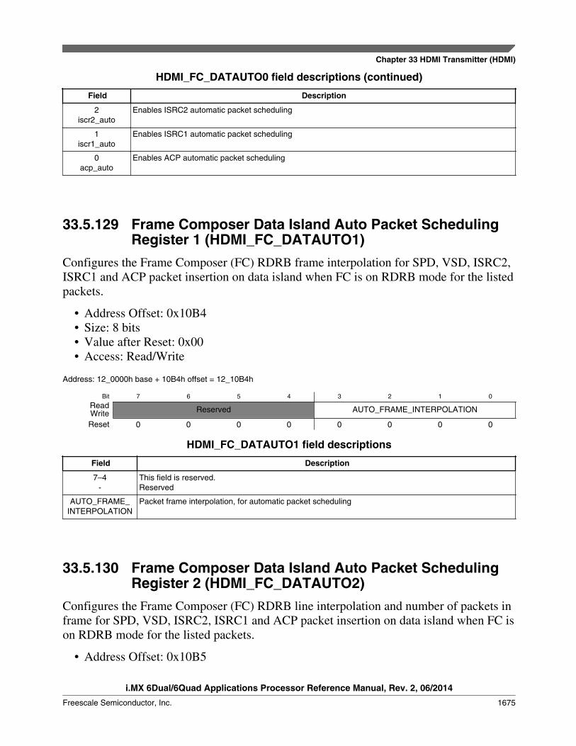
HDMI_FC_DATAUTO0 field descriptions (continued)
Field Description
2iscr2_auto
Enables ISRC2 automatic packet scheduling
1iscr1_auto
Enables ISRC1 automatic packet scheduling
0acp_auto
Enables ACP automatic packet scheduling
33.5.129 Frame Composer Data Island Auto Packet SchedulingRegister 1 (HDMI_FC_DATAUTO1)
Configures the Frame Composer (FC) RDRB frame interpolation for SPD, VSD, ISRC2,ISRC1 and ACP packet insertion on data island when FC is on RDRB mode for the listedpackets.
• Address Offset: 0x10B4• Size: 8 bits• Value after Reset: 0x00• Access: Read/Write
Address: 12_0000h base + 10B4h offset = 12_10B4h
Bit 7 6 5 4 3 2 1 0
Read Reserved AUTO_FRAME_INTERPOLATIONWriteReset 0 0 0 0 0 0 0 0
HDMI_FC_DATAUTO1 field descriptions
Field Description
7–4-
This field is reserved.Reserved
AUTO_FRAME_INTERPOLATION
Packet frame interpolation, for automatic packet scheduling
33.5.130 Frame Composer Data Island Auto Packet SchedulingRegister 2 (HDMI_FC_DATAUTO2)
Configures the Frame Composer (FC) RDRB line interpolation and number of packets inframe for SPD, VSD, ISRC2, ISRC1 and ACP packet insertion on data island when FC ison RDRB mode for the listed packets.
• Address Offset: 0x10B5
Chapter 33 HDMI Transmitter (HDMI)
i.MX 6Dual/6Quad Applications Processor Reference Manual, Rev. 2, 06/2014
Freescale Semiconductor, Inc. 1675
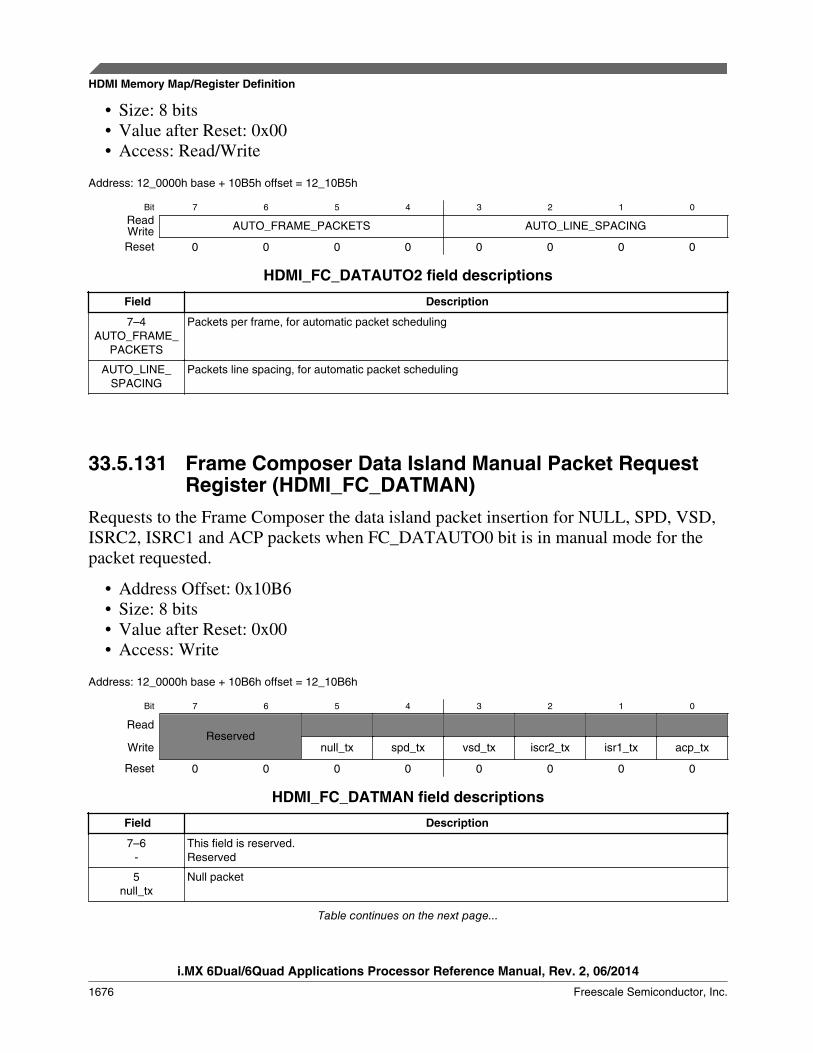
• Size: 8 bits• Value after Reset: 0x00• Access: Read/Write
Address: 12_0000h base + 10B5h offset = 12_10B5h
Bit 7 6 5 4 3 2 1 0
Read AUTO_FRAME_PACKETS AUTO_LINE_SPACINGWriteReset 0 0 0 0 0 0 0 0
HDMI_FC_DATAUTO2 field descriptions
Field Description
7–4AUTO_FRAME_
PACKETS
Packets per frame, for automatic packet scheduling
AUTO_LINE_SPACING
Packets line spacing, for automatic packet scheduling
33.5.131 Frame Composer Data Island Manual Packet RequestRegister (HDMI_FC_DATMAN)
Requests to the Frame Composer the data island packet insertion for NULL, SPD, VSD,ISRC2, ISRC1 and ACP packets when FC_DATAUTO0 bit is in manual mode for thepacket requested.
• Address Offset: 0x10B6• Size: 8 bits• Value after Reset: 0x00• Access: Write
Address: 12_0000h base + 10B6h offset = 12_10B6h
Bit 7 6 5 4 3 2 1 0
ReadReserved
Write null_tx spd_tx vsd_tx iscr2_tx isr1_tx acp_tx
Reset 0 0 0 0 0 0 0 0
HDMI_FC_DATMAN field descriptions
Field Description
7–6-
This field is reserved.Reserved
5null_tx
Null packet
Table continues on the next page...
HDMI Memory Map/Register Definition
i.MX 6Dual/6Quad Applications Processor Reference Manual, Rev. 2, 06/2014
1676 Freescale Semiconductor, Inc.

HDMI_FC_DATMAN field descriptions (continued)
Field Description
4spd_tx
SPD packet
3vsd_tx
VSD packet
2iscr2_tx
ISRC2 packet
1isr1_tx
ISRC1 packet
0acp_tx
ACP packet
33.5.132 Frame Composer Data Island Auto Packet SchedulingRegister 3 (HDMI_FC_DATAUTO3)
Configures the Frame Composer Automatic(1)/RDRB(0) data island packet insertion forAVI, GCP, AUDI and ACR packets. In Automatic mode, the packet will be inserted onVblanking when first line with active Vsync appears.
• Address Offset: 0x10B7• Size: 8 bits• Value after Reset: 0x0F• Access: Read/Write
Address: 12_0000h base + 10B7h offset = 12_10B7h
Bit 7 6 5 4 3 2 1 0
Read Reserved avi_auto gcp_auto audi_auto acr_autoWriteReset 0 0 0 0 1 1 1 1
HDMI_FC_DATAUTO3 field descriptions
Field Description
7–4-
This field is reserved.Reserved
3avi_auto
Enable AVI packet insertion
2gcp_auto
Enable GCP packet insertion
1audi_auto
Enable AUDI packet insertion
0acr_auto
Enable ACR packet insertion
Chapter 33 HDMI Transmitter (HDMI)
i.MX 6Dual/6Quad Applications Processor Reference Manual, Rev. 2, 06/2014
Freescale Semiconductor, Inc. 1677

33.5.133 Frame Composer Round Robin ACR Packet InsertionRegister 0 (HDMI_FC_RDRB0)
Configures the Frame Composer (FC) RDRB frame interpolation for ACR packetinsertion on data island when FC is on RDRB mode for this packet.
• Address Offset: 0x10B8• Size: 8 bits• Value after Reset: 0x00• Access: Read/Write
Address: 12_0000h base + 10B8h offset = 12_10B8h
Bit 7 6 5 4 3 2 1 0
Read Reserved ACRframeinterpolationWriteReset 0 0 0 0 0 0 0 0
HDMI_FC_RDRB0 field descriptions
Field Description
7–4-
This field is reserved.Reserved
ACRframeinterpolation ACR frame interpolation
33.5.134 Frame Composer Round Robin ACR Packet InsertionRegister 1 (HDMI_FC_RDRB1)
Configures the Frame Composer (FC) RDRB line interpolation and number of packets inframe for the ACR packet insertion on data island when FC is on RDRB mode thispacket.
• Address Offset: 0x10B9• Size: 8 bits• Value after Reset: 0x00• Access: Read/Write
Address: 12_0000h base + 10B9h offset = 12_10B9h
Bit 7 6 5 4 3 2 1 0
Read ACRpacketsinframe ACRpacketlinespacingWriteReset 0 0 0 0 0 0 0 0
HDMI Memory Map/Register Definition
i.MX 6Dual/6Quad Applications Processor Reference Manual, Rev. 2, 06/2014
1678 Freescale Semiconductor, Inc.
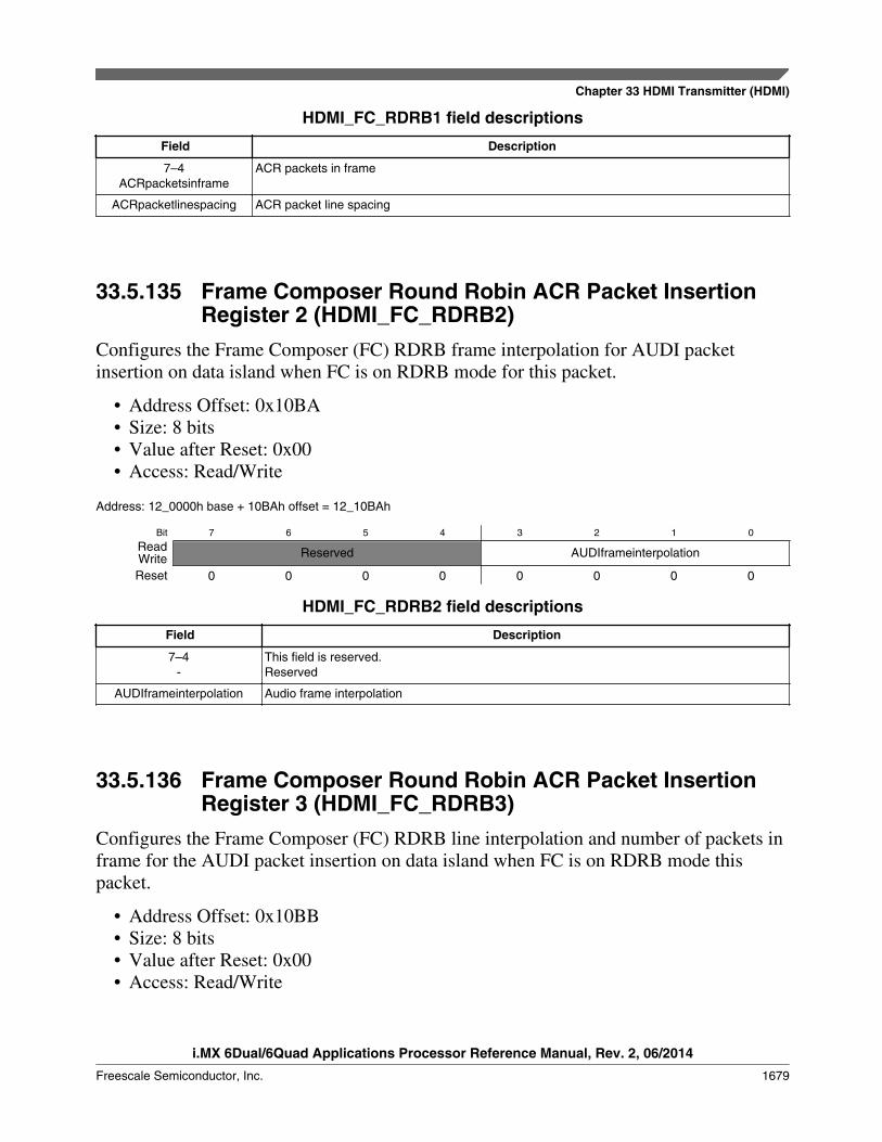
HDMI_FC_RDRB1 field descriptions
Field Description
7–4ACRpacketsinframe
ACR packets in frame
ACRpacketlinespacing ACR packet line spacing
33.5.135 Frame Composer Round Robin ACR Packet InsertionRegister 2 (HDMI_FC_RDRB2)
Configures the Frame Composer (FC) RDRB frame interpolation for AUDI packetinsertion on data island when FC is on RDRB mode for this packet.
• Address Offset: 0x10BA• Size: 8 bits• Value after Reset: 0x00• Access: Read/Write
Address: 12_0000h base + 10BAh offset = 12_10BAh
Bit 7 6 5 4 3 2 1 0
Read Reserved AUDIframeinterpolationWriteReset 0 0 0 0 0 0 0 0
HDMI_FC_RDRB2 field descriptions
Field Description
7–4-
This field is reserved.Reserved
AUDIframeinterpolation Audio frame interpolation
33.5.136 Frame Composer Round Robin ACR Packet InsertionRegister 3 (HDMI_FC_RDRB3)
Configures the Frame Composer (FC) RDRB line interpolation and number of packets inframe for the AUDI packet insertion on data island when FC is on RDRB mode thispacket.
• Address Offset: 0x10BB• Size: 8 bits• Value after Reset: 0x00• Access: Read/Write
Chapter 33 HDMI Transmitter (HDMI)
i.MX 6Dual/6Quad Applications Processor Reference Manual, Rev. 2, 06/2014
Freescale Semiconductor, Inc. 1679
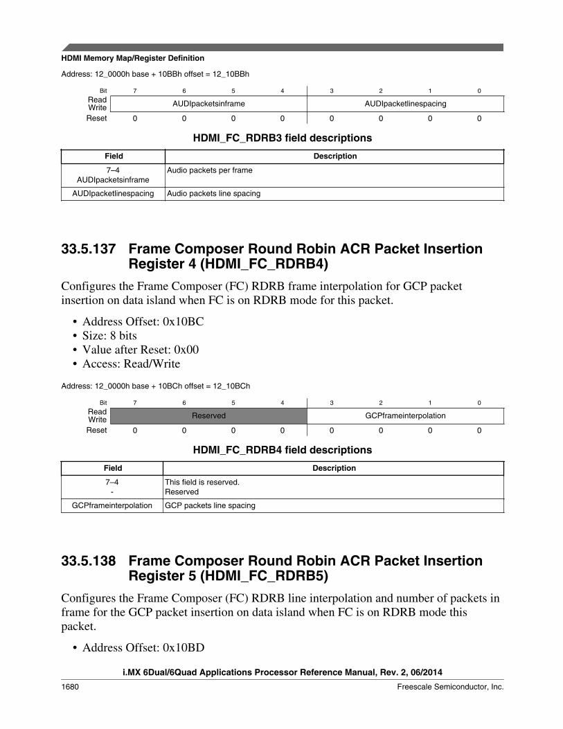
Address: 12_0000h base + 10BBh offset = 12_10BBh
Bit 7 6 5 4 3 2 1 0
Read AUDIpacketsinframe AUDIpacketlinespacingWriteReset 0 0 0 0 0 0 0 0
HDMI_FC_RDRB3 field descriptions
Field Description
7–4AUDIpacketsinframe
Audio packets per frame
AUDIpacketlinespacing Audio packets line spacing
33.5.137 Frame Composer Round Robin ACR Packet InsertionRegister 4 (HDMI_FC_RDRB4)
Configures the Frame Composer (FC) RDRB frame interpolation for GCP packetinsertion on data island when FC is on RDRB mode for this packet.
• Address Offset: 0x10BC• Size: 8 bits• Value after Reset: 0x00• Access: Read/Write
Address: 12_0000h base + 10BCh offset = 12_10BCh
Bit 7 6 5 4 3 2 1 0
Read Reserved GCPframeinterpolationWriteReset 0 0 0 0 0 0 0 0
HDMI_FC_RDRB4 field descriptions
Field Description
7–4-
This field is reserved.Reserved
GCPframeinterpolation GCP packets line spacing
33.5.138 Frame Composer Round Robin ACR Packet InsertionRegister 5 (HDMI_FC_RDRB5)
Configures the Frame Composer (FC) RDRB line interpolation and number of packets inframe for the GCP packet insertion on data island when FC is on RDRB mode thispacket.
• Address Offset: 0x10BD
HDMI Memory Map/Register Definition
i.MX 6Dual/6Quad Applications Processor Reference Manual, Rev. 2, 06/2014
1680 Freescale Semiconductor, Inc.
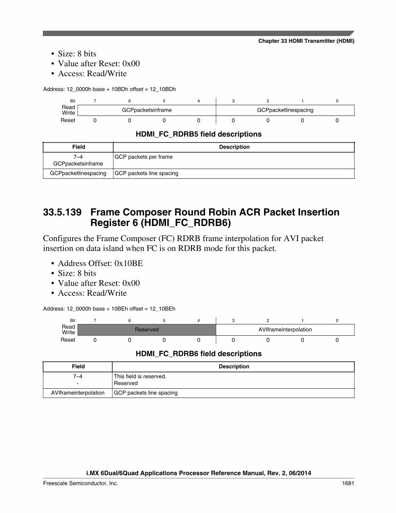
• Size: 8 bits• Value after Reset: 0x00• Access: Read/Write
Address: 12_0000h base + 10BDh offset = 12_10BDh
Bit 7 6 5 4 3 2 1 0
Read GCPpacketsinframe GCPpacketlinespacingWriteReset 0 0 0 0 0 0 0 0
HDMI_FC_RDRB5 field descriptions
Field Description
7–4GCPpacketsinframe
GCP packets per frame
GCPpacketlinespacing GCP packets line spacing
33.5.139 Frame Composer Round Robin ACR Packet InsertionRegister 6 (HDMI_FC_RDRB6)
Configures the Frame Composer (FC) RDRB frame interpolation for AVI packetinsertion on data island when FC is on RDRB mode for this packet.
• Address Offset: 0x10BE• Size: 8 bits• Value after Reset: 0x00• Access: Read/Write
Address: 12_0000h base + 10BEh offset = 12_10BEh
Bit 7 6 5 4 3 2 1 0
Read Reserved AVIframeinterpolationWriteReset 0 0 0 0 0 0 0 0
HDMI_FC_RDRB6 field descriptions
Field Description
7–4-
This field is reserved.Reserved
AVIframeinterpolation GCP packets line spacing
Chapter 33 HDMI Transmitter (HDMI)
i.MX 6Dual/6Quad Applications Processor Reference Manual, Rev. 2, 06/2014
Freescale Semiconductor, Inc. 1681
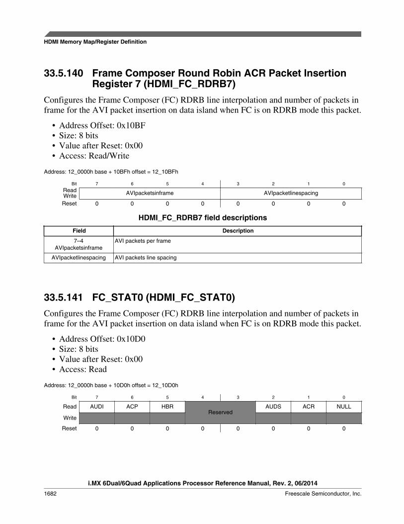
33.5.140 Frame Composer Round Robin ACR Packet InsertionRegister 7 (HDMI_FC_RDRB7)
Configures the Frame Composer (FC) RDRB line interpolation and number of packets inframe for the AVI packet insertion on data island when FC is on RDRB mode this packet.
• Address Offset: 0x10BF• Size: 8 bits• Value after Reset: 0x00• Access: Read/Write
Address: 12_0000h base + 10BFh offset = 12_10BFh
Bit 7 6 5 4 3 2 1 0
Read AVIpacketsinframe AVIpacketlinespacingWriteReset 0 0 0 0 0 0 0 0
HDMI_FC_RDRB7 field descriptions
Field Description
7–4AVIpacketsinframe
AVI packets per frame
AVIpacketlinespacing AVI packets line spacing
33.5.141 FC_STAT0 (HDMI_FC_STAT0)Configures the Frame Composer (FC) RDRB line interpolation and number of packets inframe for the AVI packet insertion on data island when FC is on RDRB mode this packet.
• Address Offset: 0x10D0• Size: 8 bits• Value after Reset: 0x00• Access: Read
Address: 12_0000h base + 10D0h offset = 12_10D0h
Bit 7 6 5 4 3 2 1 0
Read AUDI ACP HBRReserved
AUDS ACR NULL
Write
Reset 0 0 0 0 0 0 0 0
HDMI Memory Map/Register Definition
i.MX 6Dual/6Quad Applications Processor Reference Manual, Rev. 2, 06/2014
1682 Freescale Semiconductor, Inc.

HDMI_FC_STAT0 field descriptions
Field Description
7AUDI
Status bit
Active after successful transmission of an Audio InfoFrame packet.
6ACP
Status bit. Active after successful transmission of an Audio Content Protection Packet.
5HBR
Status bit. Active after successful transmission of an Audio HBR packet
4–3-
This field is reserved.Reserved
2AUDS
Status bit
Active after successful transmission of an Audio Sample packet.
1ACR
Status bit
Active after successful transmission of an Audio Clock Regeneration (N/CTS transmission) packet.
0NULL
Status bit
Active after successful transmission of an Null packet.
33.5.142 FC_INT0 (HDMI_FC_INT0)This register contains the interrupt indication of the FC_STAT0 status interrupts.Interrupt generation is accomplished in the following way:
interrupt = (mask == 1'b0) && (polarity == status);
All this interrupts are forwarded to the Interrupt Handler sticky bit registers and afterORed to a single main interrupt line to micro controller. Assertion of this interruptimplies that data related with the corresponding packet has been sent through the HDMIinterface.
• Address Offset: 0x10D1• Size: 8 bits• Value after Reset: 0x00• Access: Read/Write
Address: 12_0000h base + 10D1h offset = 12_10D1h
Bit 7 6 5 4 3 2 1 0
Read AUDI ACP HBR Reserved AUDS ACR NULLWriteReset 0 0 0 0 0 0 0 0
HDMI_FC_INT0 field descriptions
Field Description
7AUDI
Interrupt indication bit
Table continues on the next page...
Chapter 33 HDMI Transmitter (HDMI)
i.MX 6Dual/6Quad Applications Processor Reference Manual, Rev. 2, 06/2014
Freescale Semiconductor, Inc. 1683

HDMI_FC_INT0 field descriptions (continued)
Field DescriptionActive after successful transmission of an Audio InfoFrame packet interrupt.
6ACP
Interrupt indication bit
Active after successful transmission of an Audio Content Protection packet interrupt.
5HBR
Interrupt indication bit
Active after successful transmission of a Audio HBR packet interrupt.
4–3-
This field is reserved.Reserved
2AUDS
Interrupt indication bit
Active after successful transmission of an Audio Sample packet interrupt.
1ACR
Interrupt indication bit
Active after successful transmission of an Audio Clock Regeneration (N/CTS transmission) packetinterrupt.
0NULL
Interrupt indication bit
Active after successful transmission of an Null packet interrupt.
33.5.143 Frame Composer Packet Interrupt Mask Register 0(HDMI_FC_MASK0)
Mask register for generation of FC_INT0 interrupts.
• Address Offset: 0x10D2• Size: 8 bits• Value after Reset: 0x25• Access: Read/Write
Address: 12_0000h base + 10D2h offset = 12_10D2h
Bit 7 6 5 4 3 2 1 0
Read AUDI ACP HBR Reserved AUDS ACR NULLWriteReset 0 0 1 0 0 1 0 1
HDMI_FC_MASK0 field descriptions
Field Description
7AUDI
Mask bit for FC_INT0.AUDI interrupt bit
Value after Reset: 0b
6ACP
Mask bit for FC_INT0.ACP interrupt bit
Value after Reset: 0b
5HBR
Mask bit for FC_INT0.HBR interrupt bit
Value after Reset: 0b
Table continues on the next page...
HDMI Memory Map/Register Definition
i.MX 6Dual/6Quad Applications Processor Reference Manual, Rev. 2, 06/2014
1684 Freescale Semiconductor, Inc.
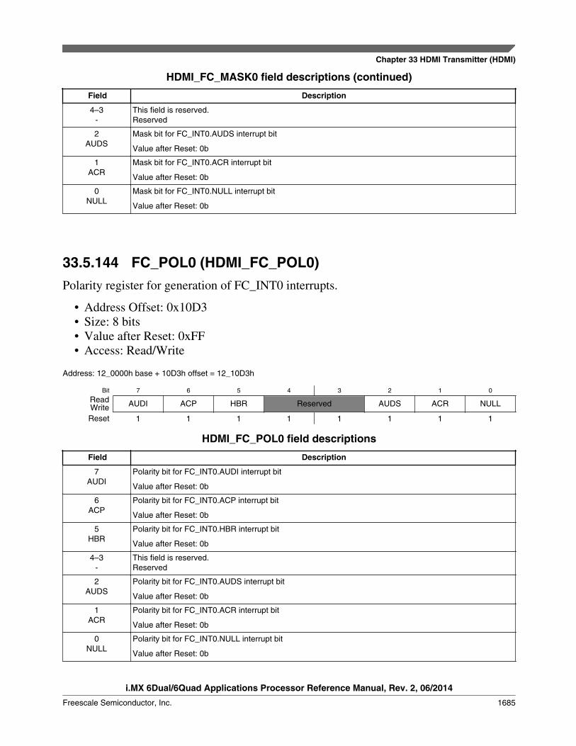
HDMI_FC_MASK0 field descriptions (continued)
Field Description
4–3-
This field is reserved.Reserved
2AUDS
Mask bit for FC_INT0.AUDS interrupt bit
Value after Reset: 0b
1ACR
Mask bit for FC_INT0.ACR interrupt bit
Value after Reset: 0b
0NULL
Mask bit for FC_INT0.NULL interrupt bit
Value after Reset: 0b
33.5.144 FC_POL0 (HDMI_FC_POL0)Polarity register for generation of FC_INT0 interrupts.
• Address Offset: 0x10D3• Size: 8 bits• Value after Reset: 0xFF• Access: Read/Write
Address: 12_0000h base + 10D3h offset = 12_10D3h
Bit 7 6 5 4 3 2 1 0
Read AUDI ACP HBR Reserved AUDS ACR NULLWriteReset 1 1 1 1 1 1 1 1
HDMI_FC_POL0 field descriptions
Field Description
7AUDI
Polarity bit for FC_INT0.AUDI interrupt bit
Value after Reset: 0b
6ACP
Polarity bit for FC_INT0.ACP interrupt bit
Value after Reset: 0b
5HBR
Polarity bit for FC_INT0.HBR interrupt bit
Value after Reset: 0b
4–3-
This field is reserved.Reserved
2AUDS
Polarity bit for FC_INT0.AUDS interrupt bit
Value after Reset: 0b
1ACR
Polarity bit for FC_INT0.ACR interrupt bit
Value after Reset: 0b
0NULL
Polarity bit for FC_INT0.NULL interrupt bit
Value after Reset: 0b
Chapter 33 HDMI Transmitter (HDMI)
i.MX 6Dual/6Quad Applications Processor Reference Manual, Rev. 2, 06/2014
Freescale Semiconductor, Inc. 1685

33.5.145 FC_STAT1 (HDMI_FC_STAT1)This register contains the following active high packet sent status indications:
• Address Offset: 0x10D4• Size: 8 bits• Value after Reset: 0x00• Access: Read/Write
Address: 12_0000h base + 10D4h offset = 12_10D4h
Bit 7 6 5 4 3 2 1 0
Read GMD ISCR1 ISCR2 VSD SPD Reserved AVI GCPWriteReset 0 0 0 0 0 0 0 0
HDMI_FC_STAT1 field descriptions
Field Description
7GMD
Status bit
Active after successful transmission of an Gamut metadata packet.
6ISCR1
Status bit
Active after successful transmission of an International Standard Recording Code 1 packet.
5ISCR2
Active after successful transmission of an International Standard Recording Code 2 packet.
4VSD
Active after successful transmission of an Vendor Specific Data infoFrame packet.
3SPD
Active after successful transmission of an Source Product Descriptor infoFrame packet.
2-
This field is reserved.Reserved
1AVI
Status bit
Active after successful transmission of an AVI infoFrame packet.
0GCP
Status bit
Active after successful transmission of an General Content Packet.
33.5.146 FC_INT1 (HDMI_FC_INT1)This register contains the interrupt indication of the FC_STAT1 status interrupts.Interrupt generation is accomplished in the following way:
interrupt = (mask == 1'b0) && (polarity == status);
HDMI Memory Map/Register Definition
i.MX 6Dual/6Quad Applications Processor Reference Manual, Rev. 2, 06/2014
1686 Freescale Semiconductor, Inc.
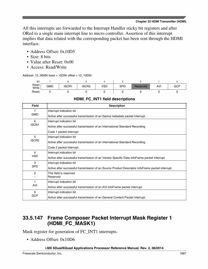
All this interrupts are forwarded to the Interrupt Handler sticky bit registers and afterORed to a single main interrupt line to micro controller. Assertion of this interruptimplies that data related with the corresponding packet has been sent through the HDMIinterface.
• Address Offset: 0x10D5• Size: 8 bits• Value after Reset: 0x00• Access: Read/Write
Address: 12_0000h base + 10D5h offset = 12_10D5h
Bit 7 6 5 4 3 2 1 0
Read GMD ISCR1 ISCR2 VSD SPD Reserved AVI GCPWriteReset 0 0 0 0 0 0 0 0
HDMI_FC_INT1 field descriptions
Field Description
7GMD
Interrupt indication bit
Active after successful transmission of an Gamut metadata packet interrupt.
6ISCR1
Interrupt indication bit
Active after successful transmission of an International Standard Recording
Code 1 packet interrupt.
5ISCR2
Interrupt indication bit
Active after successful transmission of an International Standard Recording
Code 2 packet interrupt.
4VSD
Interrupt indication bit
Active after successful transmission of an Vendor Specific Data infoFrame packet interrupt.
3SPD
Interrupt indication bit
Active after successful transmission of an Source Product Descriptor infoFrame packet interrupt.
2-
This field is reserved.Reserved
1AVI
Interrupt indication bit
Active after successful transmission of an AVI infoFrame packet interrupt.
0GCP
Interrupt indication bit
Active after successful transmission of an General Content Packet interrupt.
33.5.147 Frame Composer Packet Interrupt Mask Register 1(HDMI_FC_MASK1)
Mask register for generation of FC_INT1 interrupts.
• Address Offset: 0x10D6
Chapter 33 HDMI Transmitter (HDMI)
i.MX 6Dual/6Quad Applications Processor Reference Manual, Rev. 2, 06/2014
Freescale Semiconductor, Inc. 1687
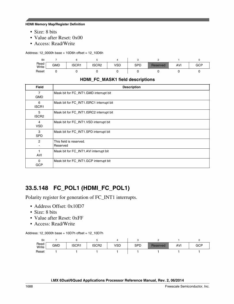
• Size: 8 bits• Value after Reset: 0x00• Access: Read/Write
Address: 12_0000h base + 10D6h offset = 12_10D6h
Bit 7 6 5 4 3 2 1 0
Read GMD ISCR1 ISCR2 VSD SPD Reserved AVI GCPWriteReset 0 0 0 0 0 0 0 0
HDMI_FC_MASK1 field descriptions
Field Description
7GMD
Mask bit for FC_INT1.GMD interrupt bit
6ISCR1
Mask bit for FC_INT1.ISRC1 interrupt bit
5ISCR2
Mask bit for FC_INT1.ISRC2 interrupt bit
4VSD
Mask bit for FC_INT1.VSD interrupt bit
3SPD
Mask bit for FC_INT1.SPD interrupt bit
2-
This field is reserved.Reserved
1AVI
Mask bit for FC_INT1.AVI interrupt bit
0GCP
Mask bit for FC_INT1.GCP interrupt bit
33.5.148 FC_POL1 (HDMI_FC_POL1)Polarity register for generation of FC_INT1 interrupts.
• Address Offset: 0x10D7• Size: 8 bits• Value after Reset: 0xFF• Access: Read/Write
Address: 12_0000h base + 10D7h offset = 12_10D7h
Bit 7 6 5 4 3 2 1 0
Read GMD ISCR1 ISCR2 VSD SPD Reserved AVI GCPWriteReset 1 1 1 1 1 1 1 1
HDMI Memory Map/Register Definition
i.MX 6Dual/6Quad Applications Processor Reference Manual, Rev. 2, 06/2014
1688 Freescale Semiconductor, Inc.
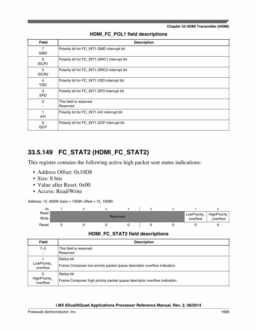
HDMI_FC_POL1 field descriptions
Field Description
7GMD
Polarity bit for FC_INT1.GMD interrupt bit
6ISCR1
Polarity bit for FC_INT1.ISRC1 interrupt bit
5ISCR2
Polarity bit for FC_INT1.ISRC2 interrupt bit
4VSD
Polarity bit for FC_INT1.VSD interrupt bit
3SPD
Polarity bit for FC_INT1.SPD interrupt bit
2-
This field is reserved.Reserved
1AVI
Polarity bit for FC_INT1.AVI interrupt bit
0GCP
Polarity bit for FC_INT1.GCP interrupt bit
33.5.149 FC_STAT2 (HDMI_FC_STAT2)This register contains the following active high packet sent status indications:
• Address Offset: 0x10D8• Size: 8 bits• Value after Reset: 0x00• Access: Read/Write
Address: 12_0000h base + 10D8h offset = 12_10D8h
Bit 7 6 5 4 3 2 1 0
ReadReserved
LowPriority_overflow
HighPriority_overflowWrite
Reset 0 0 0 0 0 0 0 0
HDMI_FC_STAT2 field descriptions
Field Description
7–2-
This field is reserved.Reserved
1LowPriority_
overflow
Status bit
Frame Composer low priority packet queue descriptor overflow indication.
0HighPriority_
overflow
Status bit
Frame Composer high priority packet queue descriptor overflow indication.
Chapter 33 HDMI Transmitter (HDMI)
i.MX 6Dual/6Quad Applications Processor Reference Manual, Rev. 2, 06/2014
Freescale Semiconductor, Inc. 1689

33.5.150 FC_INT2 (HDMI_FC_INT2)This register contains the interrupt indication of the FC_STAT2 status interrupts.Interrupt generation is accomplished in the following way:
interrupt = (mask == 1'b0) && (polarity == status);
All this interrupts are forwarded to the Interrupt Handler sticky bit registers and afterORed to a single main interrupt line to micro controller. Assertion of this interruptimplies that data related with the corresponding packet has been sent through the HDMIinterface.
• Address Offset: 0x10D9• Size: 8 bits• Value after Reset: 0x00• Access: Read/Write
Address: 12_0000h base + 10D9h offset = 12_10D9h
Bit 7 6 5 4 3 2 1 0
ReadReserved
LowPriority_overflow
HighPriority_overflowWrite
Reset 0 0 0 0 0 0 0 0
HDMI_FC_INT2 field descriptions
Field Description
7–2-
This field is reserved.Reserved
1LowPriority_
overflow
Interrupt indication bit
Frame Composer low priority packet queue descriptor overflow indication interrupt.
0HighPriority_
overflow
Interrupt indication bit
Frame Composer high priority packet queue descriptor overflow indication interrupt.
33.5.151 Frame Composer High/Low Priority Overflow InterruptMask Register 2 (HDMI_FC_MASK2)
Mask register for generation of FC_INT2 interrupts.
• Address Offset: 0x10DA• Size: 8 bits• Value after Reset: 0x00• Access: Read/Write
HDMI Memory Map/Register Definition
i.MX 6Dual/6Quad Applications Processor Reference Manual, Rev. 2, 06/2014
1690 Freescale Semiconductor, Inc.
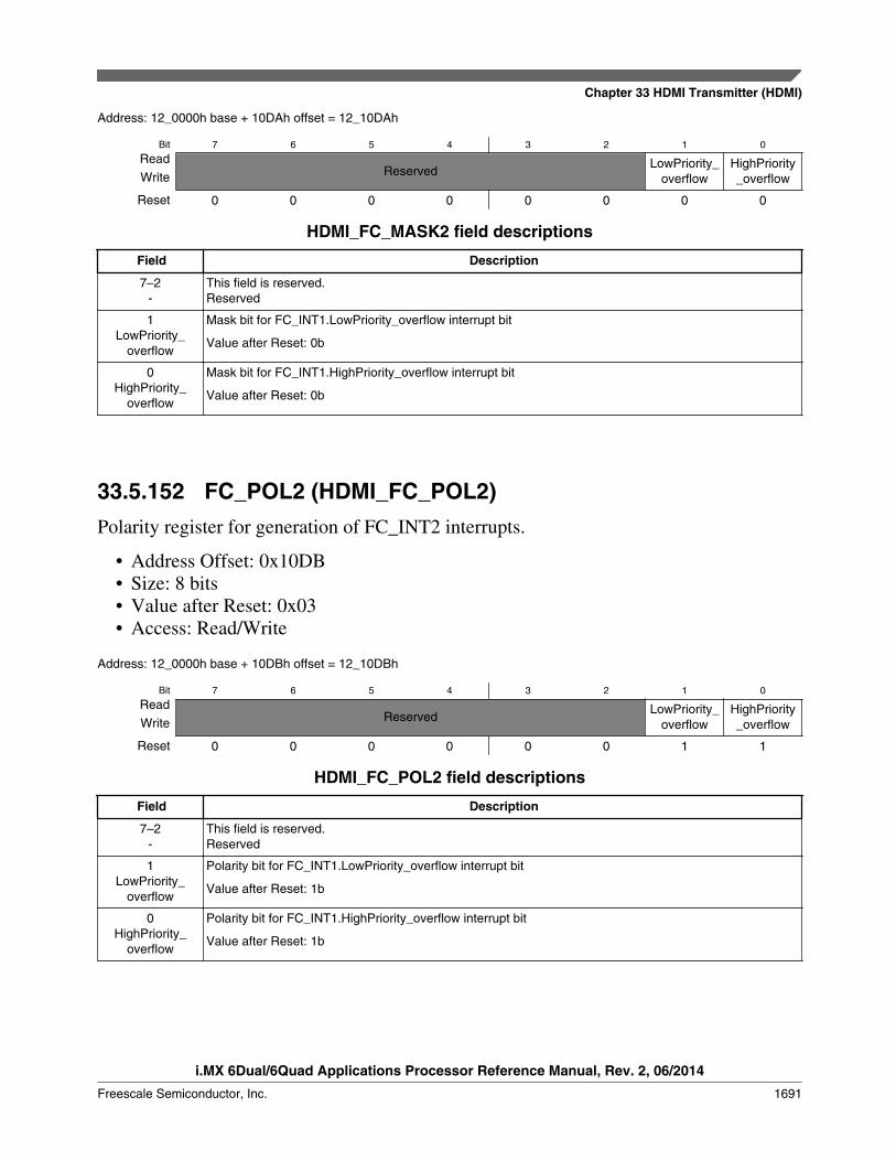
Address: 12_0000h base + 10DAh offset = 12_10DAh
Bit 7 6 5 4 3 2 1 0
ReadReserved
LowPriority_overflow
HighPriority_overflowWrite
Reset 0 0 0 0 0 0 0 0
HDMI_FC_MASK2 field descriptions
Field Description
7–2-
This field is reserved.Reserved
1LowPriority_
overflow
Mask bit for FC_INT1.LowPriority_overflow interrupt bit
Value after Reset: 0b
0HighPriority_
overflow
Mask bit for FC_INT1.HighPriority_overflow interrupt bit
Value after Reset: 0b
33.5.152 FC_POL2 (HDMI_FC_POL2)Polarity register for generation of FC_INT2 interrupts.
• Address Offset: 0x10DB• Size: 8 bits• Value after Reset: 0x03• Access: Read/Write
Address: 12_0000h base + 10DBh offset = 12_10DBh
Bit 7 6 5 4 3 2 1 0
ReadReserved
LowPriority_overflow
HighPriority_overflowWrite
Reset 0 0 0 0 0 0 1 1
HDMI_FC_POL2 field descriptions
Field Description
7–2-
This field is reserved.Reserved
1LowPriority_
overflow
Polarity bit for FC_INT1.LowPriority_overflow interrupt bit
Value after Reset: 1b
0HighPriority_
overflow
Polarity bit for FC_INT1.HighPriority_overflow interrupt bit
Value after Reset: 1b
Chapter 33 HDMI Transmitter (HDMI)
i.MX 6Dual/6Quad Applications Processor Reference Manual, Rev. 2, 06/2014
Freescale Semiconductor, Inc. 1691

33.5.153 Frame Composer Pixel Repetition ConfigurationRegister (HDMI_FC_PRCONF)
Defines the Pixel Repetition ratio factor of the input and output video signal.
• Address Offset: 0x10E0• Size: 8 bits• Value after Reset: 0x10• Access: Read/Write
Address: 12_0000h base + 10E0h offset = 12_10E0h
Bit 7 6 5 4 3 2 1 0
Read incoming_pr_factor[3:0] output_pr_factor[3:0]WriteReset 0 0 0 1 0 0 0 0
HDMI_FC_PRCONF field descriptions
Field Description
7–4incoming_pr_
factor[3:0]
Configures the input video pixel repetition. A plus 1 factor should be added in this register configuration.For CEA modes this value should be extracted from the CEA spec for the video mode being inputted.
NOTE: When working in YCC422 video the actual repetition of the stream will be Incoming_pr_factor *(desired_pr_factor + 1). This calculation is done internally in the H13TCTRL and no HW overflowprotection is available. Care must be taken to avoid this result passes the maximum number of 10pixels repeated since no HDMI support is available for this in the spec and the H13TPHY doesnot support this higher repetition values.
other: Reserved. Not used.
0000 No action. Shall not be used.0001 No pixel repetition (pixel sent only once).0010 Pixel sent twice (pixel repeated once).0011 Pixel sent 3 times.0100 Pixel sent 4 times.0101 Pixel sent 5 times.0110 Pixel sent 6 times.0111 Pixel sent 7 times.1000 Pixel sent 8 times.1001 Pixel sent 9 times.1010 Pixel sent 10 times.
output_pr_factor[3:0]
Configures the video pixel repetition ratio to be sent on the AVI infoFrame. This value must be validaccording to HDMI spec. The output_pr_factor = incoming_pr_factor(without the + 1 factor) *desired_pr_factor.
other: Reserved. Not used.
0000 No action. Shall not be used.0001 Pixel sent twice (pixel repeated once).0010 Pixel sent 3 times.0011 Pixel sent 4 times.
Table continues on the next page...
HDMI Memory Map/Register Definition
i.MX 6Dual/6Quad Applications Processor Reference Manual, Rev. 2, 06/2014
1692 Freescale Semiconductor, Inc.

HDMI_FC_PRCONF field descriptions (continued)
Field Description
0100 Pixel sent 5 times.0101 Pixel sent 6 times.0110 Pixel sent 7 times.0111 Pixel sent 8 times.1000 Pixel sent 9 times.1001 Pixel sent 10 times.
33.5.154 Frame Composer GMD Packet Status Register(HDMI_FC_GMD_STAT)
Gamut metadata packet status bit information for no_current_gmd, next_gmd_field,gmd_packet_sequence and current_gamut_seq_num. For more information, refer to theHDMI 1.4a specification.
• Address Offset: 0x1100• Size: 8 bits• Value after Reset: 0x00• Access: Read
Address: 12_0000h base + 1100h offset = 12_1100h
Bit 7 6 5 4
Read igmdno_crnt_gbd igmddnext_field igmdpacket_seq[1:0]
Write
Reset 0 0 0 0
Bit 3 2 1 0
Read igmdcurrent_gamut_seq_num[3:0]
Write
Reset 0 0 0 0
HDMI_FC_GMD_STAT field descriptions
Field Description
7igmdno_crnt_gbd
Gamut scheduling: No current gamut data
6igmddnext_field
Gamut scheduling: Gamut Next field
5–4igmdpacket_
seq[1:0]
Gamut scheduling: Gamut packet sequence
igmdcurrent_gamut_seq_
num[3:0]
Gamut scheduling: Current Gamut packet sequence number
Chapter 33 HDMI Transmitter (HDMI)
i.MX 6Dual/6Quad Applications Processor Reference Manual, Rev. 2, 06/2014
Freescale Semiconductor, Inc. 1693
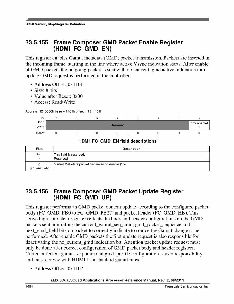
33.5.155 Frame Composer GMD Packet Enable Register(HDMI_FC_GMD_EN)
This register enables Gamut metadata (GMD) packet transmission. Packets are inserted inthe incoming frame, starting in the line where active Vsync indication starts. After enableof GMD packets the outgoing packet is sent with no_current_gmd active indication untilupdate GMD request is performed in the controller.
• Address Offset: 0x1101• Size: 8 bits• Value after Reset: 0x00• Access: Read/Write
Address: 12_0000h base + 1101h offset = 12_1101h
Bit 7 6 5 4 3 2 1 0
ReadReserved
gmdenabletxWrite
Reset 0 0 0 0 0 0 0 0
HDMI_FC_GMD_EN field descriptions
Field Description
7–1-
This field is reserved.Reserved
0gmdenabletx
Gamut Metadata packet transmission enable (1b).
33.5.156 Frame Composer GMD Packet Update Register(HDMI_FC_GMD_UP)
This register performs an GMD packet content update according to the configured packetbody (FC_GMD_PB0 to FC_GMD_PB27) and packet header (FC_GMD_HB). Thisactive high auto clear register reflects the body and header configurations on the GMDpackets sent arbitrating the current_gamut_seq_num, gmd_packet_sequence andnext_gmd_field bits on packet to correctly indicate to source the Gamut change to beperformed. After enable GMD packets the first update request is also responsible fordeactivating the no_current_gmd indication bit. Attention packet update request mustonly be done after correct configuration of GMD packet body and header registers.Correct affected_gamut_seq_num and gmd_profile configuration is user responsibilityand must convey with HDMI 1.4a standard gamut rules.
• Address Offset: 0x1102
HDMI Memory Map/Register Definition
i.MX 6Dual/6Quad Applications Processor Reference Manual, Rev. 2, 06/2014
1694 Freescale Semiconductor, Inc.

• Size: 8 bits• Value after Reset: 0x00• Access: Write
Address: 12_0000h base + 1102h offset = 12_1102h
Bit 7 6 5 4
ReadReserved
Write
Reset 0 0 0 0
Bit 3 2 1 0
ReadReserved
Write gmdupdatepacket
Reset 0 0 0 0
HDMI_FC_GMD_UP field descriptions
Field Description
7–1-
This field is reserved.Reserved
0gmdupdatepacket
Gamut Metadata packet update.
33.5.157 Frame Composer GMD Packet Schedule ConfigurationRegister (HDMI_FC_GMD_CONF)
This register configures the number of GMD packets to be inserted per frame (startingalways in the line where the active Vsync appears) and the line spacing between thetransmitted GMD packets. Note that for profile P0 (refer to HDMI 1.4a spec) this registershould only indicate one GMD packet to be inserted per video field.
• Address Offset: 0x1103• Size: 8 bits• Value after Reset: 0x10• Access: Read/Write
Address: 12_0000h base + 1103h offset = 12_1103h
Bit 7 6 5 4 3 2 1 0
Read gmdpacketsinframe[3:0] gmdpacketlinespacing[3:0]WriteReset 0 0 0 1 0 0 0 0
Chapter 33 HDMI Transmitter (HDMI)
i.MX 6Dual/6Quad Applications Processor Reference Manual, Rev. 2, 06/2014
Freescale Semiconductor, Inc. 1695

HDMI_FC_GMD_CONF field descriptions
Field Description
7–4gmdpacketsinframe[3:0]
Number of GMD packets per frame or video field (profile P0)
gmdpacketlinespacing[3:0] Number of line spacing between the transmitted GMD packets
33.5.158 Frame Composer GMD Packet Profile and GamutSequence Configuration Register (HDMI_FC_GMD_HB)
This register configures the GMD packet header affected_gamut_seq_num andgmd_profile bits. For more information, refer to the HDMI 1.4a specification.
• Address Offset: 0x1104• Size: 8 bits• Value after Reset: 0x00• Access: Read/Write
Address: 12_0000h base + 1104h offset = 12_1104h
Bit 7 6 5 4 3 2 1 0
Read Reserved gmdgbd_profile gmdaffected_gamut_seq_numWriteReset 0 0 0 0 0 0 0 0
HDMI_FC_GMD_HB field descriptions
Field Description
7-
This field is reserved.Reserved
6–4gmdgbd_profile
GMD profile bits
gmdaffected_gamut_seq_num
Affected gamut sequence number
33.5.159 Frame Composer GMD Packet Body Register 0(HDMI_FC_GMD_PB0)
Configures the following contents of the GMD packet:
• GMD packet body byte0• Address Offset: 0x1105• Size: 8 bits• Value after Reset: 0x00• Access: Read/Write
HDMI Memory Map/Register Definition
i.MX 6Dual/6Quad Applications Processor Reference Manual, Rev. 2, 06/2014
1696 Freescale Semiconductor, Inc.

For more information, refer to the HDMI 1.4a specification.
Address: 12_0000h base + 1105h offset = 12_1105h
Bit 7 6 5 4 3 2 1 0
Read FC_GMD_PB0WriteReset 0 0 0 0 0 0 0 0
HDMI_FC_GMD_PB0 field descriptions
Field Description
FC_GMD_PB0 Gamut Metadata packet byte0
33.5.160 Frame Composer GMD Packet Body Register 1(HDMI_FC_GMD_PB1)
• GMD packet body byte1• Address Offset: 0x1106• Size: 8 bits• Value after Reset: 0x00• Access: Read/Write
For more information, refer to the HDMI 1.4a specification.
Address: 12_0000h base + 1106h offset = 12_1106h
Bit 7 6 5 4 3 2 1 0
Read FC_GMD_PB1WriteReset 0 0 0 0 0 0 0 0
HDMI_FC_GMD_PB1 field descriptions
Field Description
FC_GMD_PB1 Gamut Metadata packet byte1
33.5.161 Frame Composer GMD Packet Body Register 2(HDMI_FC_GMD_PB2)
• GMD packet body byte2• Address Offset: 0x1107• Size: 8 bits• Value after Reset: 0x00• Access: Read/Write
Chapter 33 HDMI Transmitter (HDMI)
i.MX 6Dual/6Quad Applications Processor Reference Manual, Rev. 2, 06/2014
Freescale Semiconductor, Inc. 1697

For more information, refer to the HDMI 1.4a specification.
Address: 12_0000h base + 1107h offset = 12_1107h
Bit 7 6 5 4 3 2 1 0
Read FC_GMD_PB2WriteReset 0 0 0 0 0 0 0 0
HDMI_FC_GMD_PB2 field descriptions
Field Description
FC_GMD_PB2 Gamut Metadata packet byte2
33.5.162 Frame Composer GMD Packet Body Register 3(HDMI_FC_GMD_PB3)
• GMD packet body byte3• Address Offset: 0x1108• Size: 8 bits• Value after Reset: 0x00• Access: Read/Write
For more information, refer to the HDMI 1.4a specification.
Address: 12_0000h base + 1108h offset = 12_1108h
Bit 7 6 5 4 3 2 1 0
Read FC_GMD_PB3WriteReset 0 0 0 0 0 0 0 0
HDMI_FC_GMD_PB3 field descriptions
Field Description
FC_GMD_PB3 Gamut Metadata packet byte3
33.5.163 Frame Composer GMD Packet Body Register 4(HDMI_FC_GMD_PB4)
• GMD packet body byte4• Address Offset: 0x1109• Size: 8 bits• Value after Reset: 0x00• Access: Read/Write
HDMI Memory Map/Register Definition
i.MX 6Dual/6Quad Applications Processor Reference Manual, Rev. 2, 06/2014
1698 Freescale Semiconductor, Inc.

For more information, refer to the HDMI 1.4a specification.
Address: 12_0000h base + 1109h offset = 12_1109h
Bit 7 6 5 4 3 2 1 0
Read FC_GMD_PB4WriteReset 0 0 0 0 0 0 0 0
HDMI_FC_GMD_PB4 field descriptions
Field Description
FC_GMD_PB4 Gamut Metadata packet byte4
33.5.164 Frame Composer GMD Packet Body Register 5(HDMI_FC_GMD_PB5)
• GMD packet body byte5• Address Offset: 0x110a• Size: 8 bits• Value after Reset: 0x00• Access: Read/Write
For more information, refer to the HDMI 1.4a specification.
Address: 12_0000h base + 110Ah offset = 12_110Ah
Bit 7 6 5 4 3 2 1 0
Read FC_GMD_PB5WriteReset 0 0 0 0 0 0 0 0
HDMI_FC_GMD_PB5 field descriptions
Field Description
FC_GMD_PB5 Gamut Metadata packet byte5
33.5.165 Frame Composer GMD Packet Body Register 6(HDMI_FC_GMD_PB6)
• GMD packet body byte6• Address Offset: 0x110b• Size: 8 bits• Value after Reset: 0x00• Access: Read/Write
Chapter 33 HDMI Transmitter (HDMI)
i.MX 6Dual/6Quad Applications Processor Reference Manual, Rev. 2, 06/2014
Freescale Semiconductor, Inc. 1699

For more information, refer to the HDMI 1.4a specification.
Address: 12_0000h base + 110Bh offset = 12_110Bh
Bit 7 6 5 4 3 2 1 0
Read FC_GMD_PB6WriteReset 0 0 0 0 0 0 0 0
HDMI_FC_GMD_PB6 field descriptions
Field Description
FC_GMD_PB6 Gamut Metadata packet byte6
33.5.166 Frame Composer GMD Packet Body Register 7(HDMI_FC_GMD_PB7)
• GMD packet body byte7• Address Offset: 0x110c• Size: 8 bits• Value after Reset: 0x00• Access: Read/Write
For more information, refer to the HDMI 1.4a specification.
Address: 12_0000h base + 110Ch offset = 12_110Ch
Bit 7 6 5 4 3 2 1 0
Read FC_GMD_PB2WriteReset 0 0 0 0 0 0 0 0
HDMI_FC_GMD_PB7 field descriptions
Field Description
FC_GMD_PB2 Gamut Metadata packet byte7
33.5.167 Frame Composer GMD Packet Body Register 8(HDMI_FC_GMD_PB8)
• GMD packet body byte8• Address Offset: 0x110d• Size: 8 bits• Value after Reset: 0x00• Access: Read/Write
HDMI Memory Map/Register Definition
i.MX 6Dual/6Quad Applications Processor Reference Manual, Rev. 2, 06/2014
1700 Freescale Semiconductor, Inc.
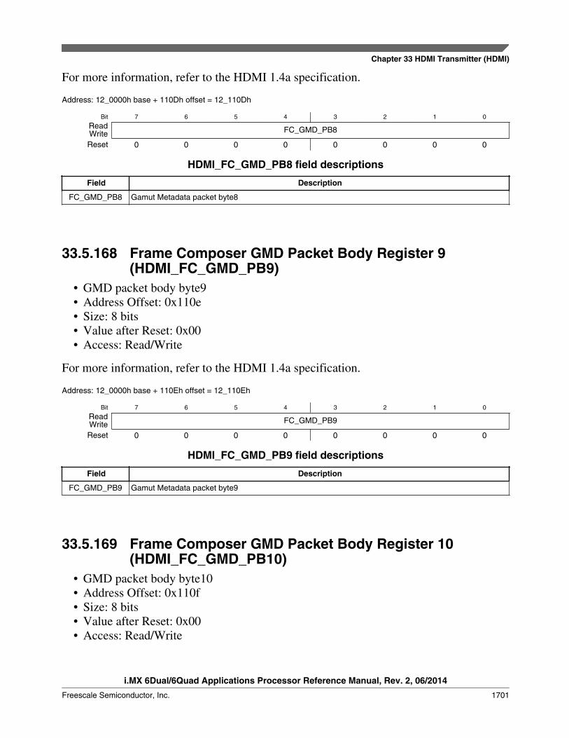
For more information, refer to the HDMI 1.4a specification.
Address: 12_0000h base + 110Dh offset = 12_110Dh
Bit 7 6 5 4 3 2 1 0
Read FC_GMD_PB8WriteReset 0 0 0 0 0 0 0 0
HDMI_FC_GMD_PB8 field descriptions
Field Description
FC_GMD_PB8 Gamut Metadata packet byte8
33.5.168 Frame Composer GMD Packet Body Register 9(HDMI_FC_GMD_PB9)
• GMD packet body byte9• Address Offset: 0x110e• Size: 8 bits• Value after Reset: 0x00• Access: Read/Write
For more information, refer to the HDMI 1.4a specification.
Address: 12_0000h base + 110Eh offset = 12_110Eh
Bit 7 6 5 4 3 2 1 0
Read FC_GMD_PB9WriteReset 0 0 0 0 0 0 0 0
HDMI_FC_GMD_PB9 field descriptions
Field Description
FC_GMD_PB9 Gamut Metadata packet byte9
33.5.169 Frame Composer GMD Packet Body Register 10(HDMI_FC_GMD_PB10)
• GMD packet body byte10• Address Offset: 0x110f• Size: 8 bits• Value after Reset: 0x00• Access: Read/Write
Chapter 33 HDMI Transmitter (HDMI)
i.MX 6Dual/6Quad Applications Processor Reference Manual, Rev. 2, 06/2014
Freescale Semiconductor, Inc. 1701
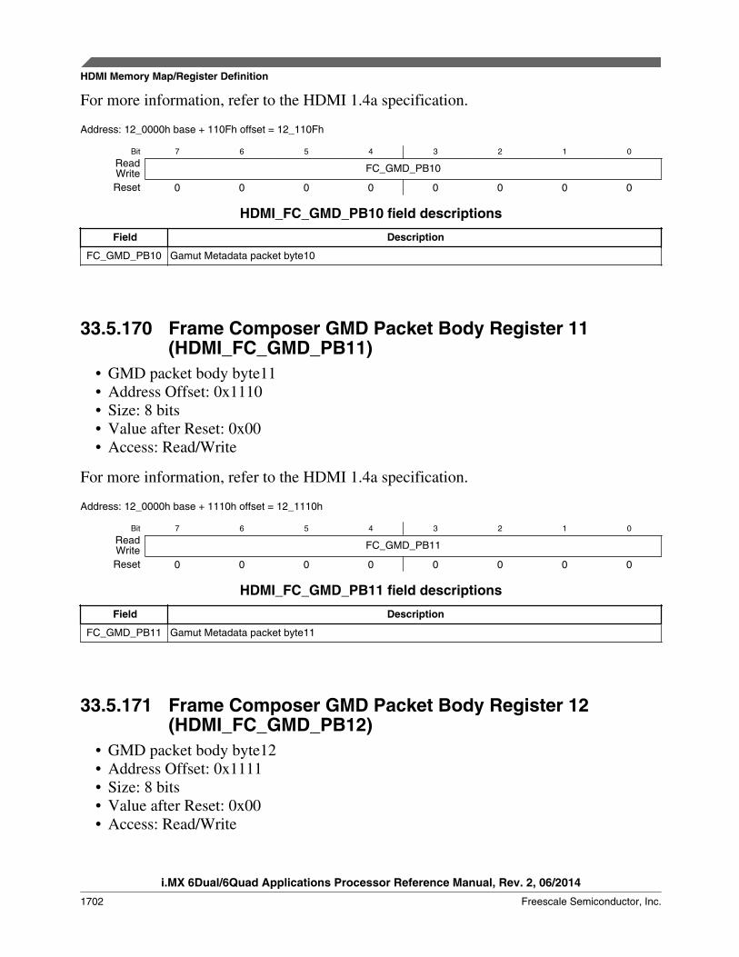
For more information, refer to the HDMI 1.4a specification.
Address: 12_0000h base + 110Fh offset = 12_110Fh
Bit 7 6 5 4 3 2 1 0
Read FC_GMD_PB10WriteReset 0 0 0 0 0 0 0 0
HDMI_FC_GMD_PB10 field descriptions
Field Description
FC_GMD_PB10 Gamut Metadata packet byte10
33.5.170 Frame Composer GMD Packet Body Register 11(HDMI_FC_GMD_PB11)
• GMD packet body byte11• Address Offset: 0x1110• Size: 8 bits• Value after Reset: 0x00• Access: Read/Write
For more information, refer to the HDMI 1.4a specification.
Address: 12_0000h base + 1110h offset = 12_1110h
Bit 7 6 5 4 3 2 1 0
Read FC_GMD_PB11WriteReset 0 0 0 0 0 0 0 0
HDMI_FC_GMD_PB11 field descriptions
Field Description
FC_GMD_PB11 Gamut Metadata packet byte11
33.5.171 Frame Composer GMD Packet Body Register 12(HDMI_FC_GMD_PB12)
• GMD packet body byte12• Address Offset: 0x1111• Size: 8 bits• Value after Reset: 0x00• Access: Read/Write
HDMI Memory Map/Register Definition
i.MX 6Dual/6Quad Applications Processor Reference Manual, Rev. 2, 06/2014
1702 Freescale Semiconductor, Inc.

For more information, refer to the HDMI 1.4a specification.
Address: 12_0000h base + 1111h offset = 12_1111h
Bit 7 6 5 4 3 2 1 0
Read FC_GMD_PB12WriteReset 0 0 0 0 0 0 0 0
HDMI_FC_GMD_PB12 field descriptions
Field Description
FC_GMD_PB12 Gamut Metadata packet byte12
33.5.172 Frame Composer GMD Packet Body Register 13(HDMI_FC_GMD_PB13)
• GMD packet body byte13• Address Offset: 0x1112• Size: 8 bits• Value after Reset: 0x00• Access: Read/Write
For more information, refer to the HDMI 1.4a specification.
Address: 12_0000h base + 1112h offset = 12_1112h
Bit 7 6 5 4 3 2 1 0
Read FC_GMD_PB13WriteReset 0 0 0 0 0 0 0 0
HDMI_FC_GMD_PB13 field descriptions
Field Description
FC_GMD_PB13 Gamut Metadata packet byte13
33.5.173 Frame Composer GMD Packet Body Register 14(HDMI_FC_GMD_PB14)
• GMD packet body byte14• Address Offset: 0x1113• Size: 8 bits• Value after Reset: 0x00• Access: Read/Write
Chapter 33 HDMI Transmitter (HDMI)
i.MX 6Dual/6Quad Applications Processor Reference Manual, Rev. 2, 06/2014
Freescale Semiconductor, Inc. 1703
For more information, refer to the HDMI 1.4a specification.
Address: 12_0000h base + 1113h offset = 12_1113h
Bit 7 6 5 4 3 2 1 0
Read FC_GMD_PB14WriteReset 0 0 0 0 0 0 0 0
HDMI_FC_GMD_PB14 field descriptions
Field Description
FC_GMD_PB14 Gamut Metadata packet byte14
33.5.174 Frame Composer GMD Packet Body Register 15(HDMI_FC_GMD_PB15)
• GMD packet body byte15• Address Offset: 0x1114• Size: 8 bits• Value after Reset: 0x00• Access: Read/Write
For more information, refer to the HDMI 1.4a specification.
Address: 12_0000h base + 1114h offset = 12_1114h
Bit 7 6 5 4 3 2 1 0
Read FC_GMD_PB15WriteReset 0 0 0 0 0 0 0 0
HDMI_FC_GMD_PB15 field descriptions
Field Description
FC_GMD_PB15 Gamut Metadata packet byte15
33.5.175 Frame Composer GMD Packet Body Register 16(HDMI_FC_GMD_PB16)
• GMD packet body byte16• Address Offset: 0x1115• Size: 8 bits• Value after Reset: 0x00• Access: Read/Write
HDMI Memory Map/Register Definition
i.MX 6Dual/6Quad Applications Processor Reference Manual, Rev. 2, 06/2014
1704 Freescale Semiconductor, Inc.

For more information, refer to the HDMI 1.4a specification.
Address: 12_0000h base + 1115h offset = 12_1115h
Bit 7 6 5 4 3 2 1 0
Read FC_GMD_PB16WriteReset 0 0 0 0 0 0 0 0
HDMI_FC_GMD_PB16 field descriptions
Field Description
FC_GMD_PB16 Gamut Metadata packet byte16
33.5.176 Frame Composer GMD Packet Body Register 17(HDMI_FC_GMD_PB17)
• GMD packet body byte17• Address Offset: 0x1116• Size: 8 bits• Value after Reset: 0x00• Access: Read/Write
For more information, refer to the HDMI 1.4a specification.
Address: 12_0000h base + 1116h offset = 12_1116h
Bit 7 6 5 4 3 2 1 0
Read FC_GMD_PB17WriteReset 0 0 0 0 0 0 0 0
HDMI_FC_GMD_PB17 field descriptions
Field Description
FC_GMD_PB17 Gamut Metadata packet byte17
33.5.177 Frame Composer GMD Packet Body Register 18(HDMI_FC_GMD_PB18)
• GMD packet body byte18• Address Offset: 0x1117• Size: 8 bits• Value after Reset: 0x00• Access: Read/Write
Chapter 33 HDMI Transmitter (HDMI)
i.MX 6Dual/6Quad Applications Processor Reference Manual, Rev. 2, 06/2014
Freescale Semiconductor, Inc. 1705
For more information, refer to the HDMI 1.4a specification.
Address: 12_0000h base + 1117h offset = 12_1117h
Bit 7 6 5 4 3 2 1 0
Read FC_GMD_PB18WriteReset 0 0 0 0 0 0 0 0
HDMI_FC_GMD_PB18 field descriptions
Field Description
FC_GMD_PB18 Gamut Metadata packet byte18
33.5.178 Frame Composer GMD Packet Body Register 19(HDMI_FC_GMD_PB19)
• GMD packet body byte19• Address Offset: 0x1118• Size: 8 bits• Value after Reset: 0x00• Access: Read/Write
For more information, refer to the HDMI 1.4a specification.
Address: 12_0000h base + 1118h offset = 12_1118h
Bit 7 6 5 4 3 2 1 0
Read FC_GMD_PB18WriteReset 0 0 0 0 0 0 0 0
HDMI_FC_GMD_PB19 field descriptions
Field Description
FC_GMD_PB18 Gamut Metadata packet byte18
33.5.179 Frame Composer GMD Packet Body Register 20(HDMI_FC_GMD_PB20)
• GMD packet body byte20• Address Offset: 0x1119• Size: 8 bits• Value after Reset: 0x00• Access: Read/Write
HDMI Memory Map/Register Definition
i.MX 6Dual/6Quad Applications Processor Reference Manual, Rev. 2, 06/2014
1706 Freescale Semiconductor, Inc.
For more information, refer to the HDMI 1.4a specification.
Address: 12_0000h base + 1119h offset = 12_1119h
Bit 7 6 5 4 3 2 1 0
Read FC_GMD_PB20WriteReset 0 0 0 0 0 0 0 0
HDMI_FC_GMD_PB20 field descriptions
Field Description
FC_GMD_PB20 Gamut Metadata packet byte20
33.5.180 Frame Composer GMD Packet Body Register 21(HDMI_FC_GMD_PB21)
• GMD packet body byte21• Address Offset: 0x111a• Size: 8 bits• Value after Reset: 0x00• Access: Read/Write
For more information, refer to the HDMI 1.4a specification.
Address: 12_0000h base + 111Ah offset = 12_111Ah
Bit 7 6 5 4 3 2 1 0
Read FC_GMD_PB21WriteReset 0 0 0 0 0 0 0 0
HDMI_FC_GMD_PB21 field descriptions
Field Description
FC_GMD_PB21 Gamut Metadata packet byte21
33.5.181 Frame Composer GMD Packet Body Register 22(HDMI_FC_GMD_PB22)
• GMD packet body byte22• Address Offset: 0x111b• Size: 8 bits• Value after Reset: 0x00• Access: Read/Write
Chapter 33 HDMI Transmitter (HDMI)
i.MX 6Dual/6Quad Applications Processor Reference Manual, Rev. 2, 06/2014
Freescale Semiconductor, Inc. 1707
For more information, refer to the HDMI 1.4a specification.
Address: 12_0000h base + 111Bh offset = 12_111Bh
Bit 7 6 5 4 3 2 1 0
Read FC_GMD_PB22WriteReset 0 0 0 0 0 0 0 0
HDMI_FC_GMD_PB22 field descriptions
Field Description
FC_GMD_PB22 Gamut Metadata packet byte22
33.5.182 Frame Composer GMD Packet Body Register 23(HDMI_FC_GMD_PB23)
• GMD packet body byte23• Address Offset: 0x111c• Size: 8 bits• Value after Reset: 0x00• Access: Read/Write
For more information, refer to the HDMI 1.4a specification.
Address: 12_0000h base + 111Ch offset = 12_111Ch
Bit 7 6 5 4 3 2 1 0
Read FC_GMD_PB23WriteReset 0 0 0 0 0 0 0 0
HDMI_FC_GMD_PB23 field descriptions
Field Description
FC_GMD_PB23 Gamut Metadata packet byte23
33.5.183 Frame Composer GMD Packet Body Register 24(HDMI_FC_GMD_PB24)
• GMD packet body byte24• Address Offset: 0x111d• Size: 8 bits• Value after Reset: 0x00• Access: Read/Write
HDMI Memory Map/Register Definition
i.MX 6Dual/6Quad Applications Processor Reference Manual, Rev. 2, 06/2014
1708 Freescale Semiconductor, Inc.
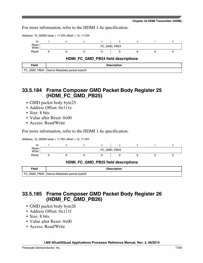
For more information, refer to the HDMI 1.4a specification.
Address: 12_0000h base + 111Dh offset = 12_111Dh
Bit 7 6 5 4 3 2 1 0
Read FC_GMD_PB24WriteReset 0 0 0 0 0 0 0 0
HDMI_FC_GMD_PB24 field descriptions
Field Description
FC_GMD_PB24 Gamut Metadata packet byte24
33.5.184 Frame Composer GMD Packet Body Register 25(HDMI_FC_GMD_PB25)
• GMD packet body byte25• Address Offset: 0x111e• Size: 8 bits• Value after Reset: 0x00• Access: Read/Write
For more information, refer to the HDMI 1.4a specification.
Address: 12_0000h base + 111Eh offset = 12_111Eh
Bit 7 6 5 4 3 2 1 0
Read FC_GMD_PB25WriteReset 0 0 0 0 0 0 0 0
HDMI_FC_GMD_PB25 field descriptions
Field Description
FC_GMD_PB25 Gamut Metadata packet byte25
33.5.185 Frame Composer GMD Packet Body Register 26(HDMI_FC_GMD_PB26)
• GMD packet body byte26• Address Offset: 0x111f• Size: 8 bits• Value after Reset: 0x00• Access: Read/Write
Chapter 33 HDMI Transmitter (HDMI)
i.MX 6Dual/6Quad Applications Processor Reference Manual, Rev. 2, 06/2014
Freescale Semiconductor, Inc. 1709

For more information, refer to the HDMI 1.4a specification.
Address: 12_0000h base + 111Fh offset = 12_111Fh
Bit 7 6 5 4 3 2 1 0
Read FC_GMD_PB26WriteReset 0 0 0 0 0 0 0 0
HDMI_FC_GMD_PB26 field descriptions
Field Description
FC_GMD_PB26 Gamut Metadata packet byte26
33.5.186 Frame Composer GMD Packet Body Register 27(HDMI_FC_GMD_PB27)
• GMD packet body byte27• Address Offset: 0x1120• Size: 8 bits• Value after Reset: 0x00• Access: Read/Write
For more information, refer to the HDMI 1.4a specification.
Address: 12_0000h base + 1120h offset = 12_1120h
Bit 7 6 5 4 3 2 1 0
Read FC_GMD_PB27WriteReset 0 0 0 0 0 0 0 0
HDMI_FC_GMD_PB27 field descriptions
Field Description
FC_GMD_PB27 Gamut Metadata packet byte27
33.5.187 Frame Composer Video/Audio Force Enable Register(HDMI_FC_DBGFORCE)
This register allows to force the controller to output audio and video data the valuesconfigured in the FC_DBGAUD and FC_DBGTMDS registers.
• Address Offset: 0x1200• Size: 8 bits
HDMI Memory Map/Register Definition
i.MX 6Dual/6Quad Applications Processor Reference Manual, Rev. 2, 06/2014
1710 Freescale Semiconductor, Inc.

• Value after Reset: 0x00• Access: Read/Write
Address: 12_0000h base + 1200h offset = 12_1200h
Bit 7 6 5 4 3 2 1 0
Read Reserved forceaudio Reserved forcevideoWriteReset 0 0 0 0 0 0 0 0
HDMI_FC_DBGFORCE field descriptions
Field Description
7–5-
This field is reserved.Reserved
4forceaudio
Force fixed audio output with FC_DBGAUDxCHx registers contain.
3–1-
This field is reserved.Reserved
0forcevideo
Force fixed video output with FC_DBGTMDSx registers contain.
33.5.188 Frame Composer Audio Channel 0 Register 0(HDMI_FC_DBGAUD0CH0)
Configures the audio fixed data to be used in channel 0 when in fixed audio selection.
• Address Offset: 0x1201• Size: 8 bits• Value after Reset: 0x00• Access: Read/Write
Address: 12_0000h base + 1201h offset = 12_1201h
Bit 7 6 5 4 3 2 1 0
Read FC_DBGAUD0CH0WriteReset 0 0 0 0 0 0 0 0
HDMI_FC_DBGAUD0CH0 field descriptions
Field Description
FC_DBGAUD0CH0
the audio fixed data byte0 to be used in channel 0 when in fixed audio selection
Chapter 33 HDMI Transmitter (HDMI)
i.MX 6Dual/6Quad Applications Processor Reference Manual, Rev. 2, 06/2014
Freescale Semiconductor, Inc. 1711

33.5.189 Frame Composer Audio Channel 0 Register 1(HDMI_FC_DBGAUD1CH0)
• Address Offset: 0x1202• Size: 8 bits• Value after Reset: 0x00• Access: Read/Write
Address: 12_0000h base + 1202h offset = 12_1202h
Bit 7 6 5 4 3 2 1 0
Read FC_DBGAUD1CH0WriteReset 0 0 0 0 0 0 0 0
HDMI_FC_DBGAUD1CH0 field descriptions
Field Description
FC_DBGAUD1CH0
the audio fixed data byte1 to be used in channel 0 when in fixed audio selection
33.5.190 Frame Composer Audio Channel 0 Register 2(HDMI_FC_DBGAUD2CH0)
• Address Offset: 0x1203• Size: 8 bits• Value after Reset: 0x00• Access: Read/Write
Address: 12_0000h base + 1203h offset = 12_1203h
Bit 7 6 5 4 3 2 1 0
Read FC_DBGAUD2CH0WriteReset 0 0 0 0 0 0 0 0
HDMI_FC_DBGAUD2CH0 field descriptions
Field Description
FC_DBGAUD2CH0
the audio fixed data byte2 to be used in channel 0 when in fixed audio selection
HDMI Memory Map/Register Definition
i.MX 6Dual/6Quad Applications Processor Reference Manual, Rev. 2, 06/2014
1712 Freescale Semiconductor, Inc.

33.5.191 Frame Composer Audio Channel 1 Register 0(HDMI_FC_DBGAUD0CH1)
Configures the audio fixed data to be used in channel 0 when in fixed audio selection.
• Address Offset: 0x1204• Size: 8 bits• Value after Reset: 0x00• Access: Read/Write
Address: 12_0000h base + 1204h offset = 12_1204h
Bit 7 6 5 4 3 2 1 0
Read FC_DBGAUD0CH1WriteReset 0 0 0 0 0 0 0 0
HDMI_FC_DBGAUD0CH1 field descriptions
Field Description
FC_DBGAUD0CH1
the audio fixed data byte2 to be used in channel 0 when in fixed audio selection
33.5.192 Frame Composer Audio Channel 1 Register 1(HDMI_FC_DBGAUD1CH1)
• Address Offset: 0x1205• Size: 8 bits• Value after Reset: 0x00• Access: Read/Write
Address: 12_0000h base + 1205h offset = 12_1205h
Bit 7 6 5 4 3 2 1 0
Read FC_DBGAUD1CH1WriteReset 0 0 0 0 0 0 0 0
HDMI_FC_DBGAUD1CH1 field descriptions
Field Description
FC_DBGAUD1CH1
the audio fixed data byte1 to be used in channel 1 when in fixed audio selection
Chapter 33 HDMI Transmitter (HDMI)
i.MX 6Dual/6Quad Applications Processor Reference Manual, Rev. 2, 06/2014
Freescale Semiconductor, Inc. 1713
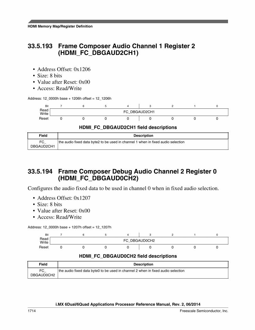
33.5.193 Frame Composer Audio Channel 1 Register 2(HDMI_FC_DBGAUD2CH1)
• Address Offset: 0x1206• Size: 8 bits• Value after Reset: 0x00• Access: Read/Write
Address: 12_0000h base + 1206h offset = 12_1206h
Bit 7 6 5 4 3 2 1 0
Read FC_DBGAUD2CH1WriteReset 0 0 0 0 0 0 0 0
HDMI_FC_DBGAUD2CH1 field descriptions
Field Description
FC_DBGAUD2CH1
the audio fixed data byte2 to be used in channel 1 when in fixed audio selection
33.5.194 Frame Composer Debug Audio Channel 2 Register 0(HDMI_FC_DBGAUD0CH2)
Configures the audio fixed data to be used in channel 0 when in fixed audio selection.
• Address Offset: 0x1207• Size: 8 bits• Value after Reset: 0x00• Access: Read/Write
Address: 12_0000h base + 1207h offset = 12_1207h
Bit 7 6 5 4 3 2 1 0
Read FC_DBGAUD0CH2WriteReset 0 0 0 0 0 0 0 0
HDMI_FC_DBGAUD0CH2 field descriptions
Field Description
FC_DBGAUD0CH2
the audio fixed data byte0 to be used in channel 2 when in fixed audio selection
HDMI Memory Map/Register Definition
i.MX 6Dual/6Quad Applications Processor Reference Manual, Rev. 2, 06/2014
1714 Freescale Semiconductor, Inc.
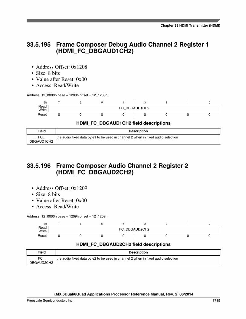
33.5.195 Frame Composer Debug Audio Channel 2 Register 1(HDMI_FC_DBGAUD1CH2)
• Address Offset: 0x1208• Size: 8 bits• Value after Reset: 0x00• Access: Read/Write
Address: 12_0000h base + 1208h offset = 12_1208h
Bit 7 6 5 4 3 2 1 0
Read FC_DBGAUD1CH2WriteReset 0 0 0 0 0 0 0 0
HDMI_FC_DBGAUD1CH2 field descriptions
Field Description
FC_DBGAUD1CH2
the audio fixed data byte1 to be used in channel 2 when in fixed audio selection
33.5.196 Frame Composer Audio Channel 2 Register 2(HDMI_FC_DBGAUD2CH2)
• Address Offset: 0x1209• Size: 8 bits• Value after Reset: 0x00• Access: Read/Write
Address: 12_0000h base + 1209h offset = 12_1209h
Bit 7 6 5 4 3 2 1 0
Read FC_DBGAUD2CH2WriteReset 0 0 0 0 0 0 0 0
HDMI_FC_DBGAUD2CH2 field descriptions
Field Description
FC_DBGAUD2CH2
the audio fixed data byte2 to be used in channel 2 when in fixed audio selection
Chapter 33 HDMI Transmitter (HDMI)
i.MX 6Dual/6Quad Applications Processor Reference Manual, Rev. 2, 06/2014
Freescale Semiconductor, Inc. 1715

33.5.197 Frame Composer Audio Channel 3 Register 0(HDMI_FC_DBGAUD0CH3)
Configures the audio fixed data to be used in channel 0 when in fixed audio selection.
• Address Offset: 0x120A• Size: 8 bits• Value after Reset: 0x00• Access: Read/Write
Address: 12_0000h base + 120Ah offset = 12_120Ah
Bit 7 6 5 4 3 2 1 0
Read FC_DBGAUD0CH3WriteReset 0 0 0 0 0 0 0 0
HDMI_FC_DBGAUD0CH3 field descriptions
Field Description
FC_DBGAUD0CH3
the audio fixed data byte0 to be used in channel 3 when in fixed audio selection
33.5.198 Frame Composer Audio Channel 3 Register 1(HDMI_FC_DBGAUD1CH3)
• Address Offset: 0x120B• Size: 8 bits• Value after Reset: 0x00• Access: Read/Write
Address: 12_0000h base + 120Bh offset = 12_120Bh
Bit 7 6 5 4 3 2 1 0
Read FC_DBGAUD1CH3WriteReset 0 0 0 0 0 0 0 0
HDMI_FC_DBGAUD1CH3 field descriptions
Field Description
FC_DBGAUD1CH3
the audio fixed data byte1 to be used in channel 3 when in fixed audio selection
HDMI Memory Map/Register Definition
i.MX 6Dual/6Quad Applications Processor Reference Manual, Rev. 2, 06/2014
1716 Freescale Semiconductor, Inc.

33.5.199 Frame Composer Audio Channel 3 Register 2(HDMI_FC_DBGAUD2CH3)
• Address Offset: 0x120C• Size: 8 bits• Value after Reset: 0x00• Access: Read/Write
Address: 12_0000h base + 120Ch offset = 12_120Ch
Bit 7 6 5 4 3 2 1 0
Read FC_DBGAUD2CH3WriteReset 0 0 0 0 0 0 0 0
HDMI_FC_DBGAUD2CH3 field descriptions
Field Description
FC_DBGAUD2CH3
the audio fixed data byte2 to be used in channel 3 when in fixed audio selection
33.5.200 Frame Composer Audio Channel 4 Register 0(HDMI_FC_DBGAUD0CH4)
Configures the audio fixed data to be used in channel 0 when in fixed audio selection.
• Address Offset: 0x120D• Size: 8 bits• Value after Reset: 0x00• Access: Read/Write
Address: 12_0000h base + 120Dh offset = 12_120Dh
Bit 7 6 5 4 3 2 1 0
Read FC_DBGAUD0CH4WriteReset 0 0 0 0 0 0 0 0
HDMI_FC_DBGAUD0CH4 field descriptions
Field Description
FC_DBGAUD0CH4
the audio fixed data byte0 to be used in channel 4 when in fixed audio selection
Chapter 33 HDMI Transmitter (HDMI)
i.MX 6Dual/6Quad Applications Processor Reference Manual, Rev. 2, 06/2014
Freescale Semiconductor, Inc. 1717
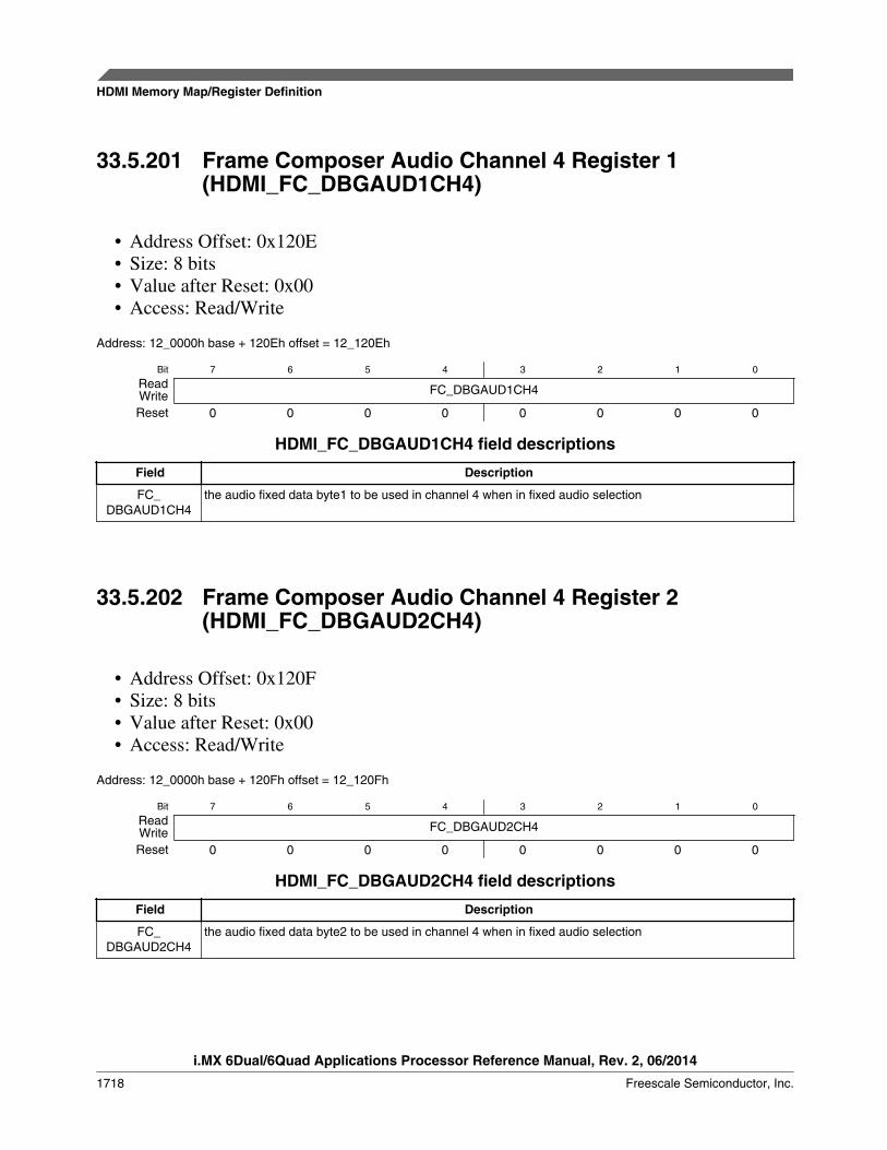
33.5.201 Frame Composer Audio Channel 4 Register 1(HDMI_FC_DBGAUD1CH4)
• Address Offset: 0x120E• Size: 8 bits• Value after Reset: 0x00• Access: Read/Write
Address: 12_0000h base + 120Eh offset = 12_120Eh
Bit 7 6 5 4 3 2 1 0
Read FC_DBGAUD1CH4WriteReset 0 0 0 0 0 0 0 0
HDMI_FC_DBGAUD1CH4 field descriptions
Field Description
FC_DBGAUD1CH4
the audio fixed data byte1 to be used in channel 4 when in fixed audio selection
33.5.202 Frame Composer Audio Channel 4 Register 2(HDMI_FC_DBGAUD2CH4)
• Address Offset: 0x120F• Size: 8 bits• Value after Reset: 0x00• Access: Read/Write
Address: 12_0000h base + 120Fh offset = 12_120Fh
Bit 7 6 5 4 3 2 1 0
Read FC_DBGAUD2CH4WriteReset 0 0 0 0 0 0 0 0
HDMI_FC_DBGAUD2CH4 field descriptions
Field Description
FC_DBGAUD2CH4
the audio fixed data byte2 to be used in channel 4 when in fixed audio selection
HDMI Memory Map/Register Definition
i.MX 6Dual/6Quad Applications Processor Reference Manual, Rev. 2, 06/2014
1718 Freescale Semiconductor, Inc.
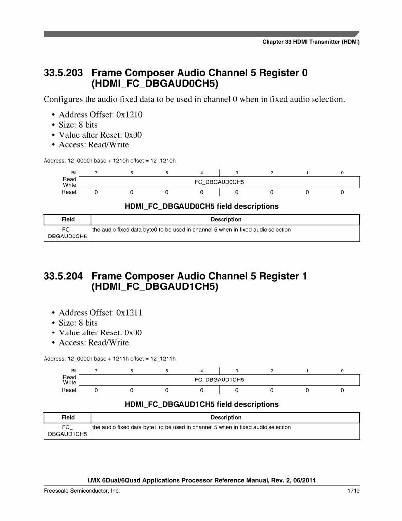
33.5.203 Frame Composer Audio Channel 5 Register 0(HDMI_FC_DBGAUD0CH5)
Configures the audio fixed data to be used in channel 0 when in fixed audio selection.
• Address Offset: 0x1210• Size: 8 bits• Value after Reset: 0x00• Access: Read/Write
Address: 12_0000h base + 1210h offset = 12_1210h
Bit 7 6 5 4 3 2 1 0
Read FC_DBGAUD0CH5WriteReset 0 0 0 0 0 0 0 0
HDMI_FC_DBGAUD0CH5 field descriptions
Field Description
FC_DBGAUD0CH5
the audio fixed data byte0 to be used in channel 5 when in fixed audio selection
33.5.204 Frame Composer Audio Channel 5 Register 1(HDMI_FC_DBGAUD1CH5)
• Address Offset: 0x1211• Size: 8 bits• Value after Reset: 0x00• Access: Read/Write
Address: 12_0000h base + 1211h offset = 12_1211h
Bit 7 6 5 4 3 2 1 0
Read FC_DBGAUD1CH5WriteReset 0 0 0 0 0 0 0 0
HDMI_FC_DBGAUD1CH5 field descriptions
Field Description
FC_DBGAUD1CH5
the audio fixed data byte1 to be used in channel 5 when in fixed audio selection
Chapter 33 HDMI Transmitter (HDMI)
i.MX 6Dual/6Quad Applications Processor Reference Manual, Rev. 2, 06/2014
Freescale Semiconductor, Inc. 1719
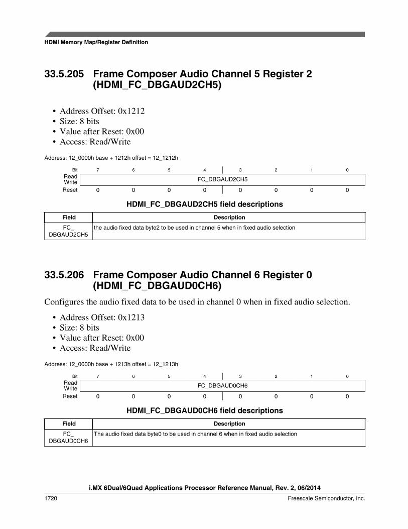
33.5.205 Frame Composer Audio Channel 5 Register 2(HDMI_FC_DBGAUD2CH5)
• Address Offset: 0x1212• Size: 8 bits• Value after Reset: 0x00• Access: Read/Write
Address: 12_0000h base + 1212h offset = 12_1212h
Bit 7 6 5 4 3 2 1 0
Read FC_DBGAUD2CH5WriteReset 0 0 0 0 0 0 0 0
HDMI_FC_DBGAUD2CH5 field descriptions
Field Description
FC_DBGAUD2CH5
the audio fixed data byte2 to be used in channel 5 when in fixed audio selection
33.5.206 Frame Composer Audio Channel 6 Register 0(HDMI_FC_DBGAUD0CH6)
Configures the audio fixed data to be used in channel 0 when in fixed audio selection.
• Address Offset: 0x1213• Size: 8 bits• Value after Reset: 0x00• Access: Read/Write
Address: 12_0000h base + 1213h offset = 12_1213h
Bit 7 6 5 4 3 2 1 0
Read FC_DBGAUD0CH6WriteReset 0 0 0 0 0 0 0 0
HDMI_FC_DBGAUD0CH6 field descriptions
Field Description
FC_DBGAUD0CH6
The audio fixed data byte0 to be used in channel 6 when in fixed audio selection
HDMI Memory Map/Register Definition
i.MX 6Dual/6Quad Applications Processor Reference Manual, Rev. 2, 06/2014
1720 Freescale Semiconductor, Inc.

33.5.207 Frame Composer Audio Channel 6 Register 1(HDMI_FC_DBGAUD1CH6)
• Address Offset: 0x1214• Size: 8 bits• Value after Reset: 0x00• Access: Read/Write
Address: 12_0000h base + 1214h offset = 12_1214h
Bit 7 6 5 4 3 2 1 0
Read FC_DBGAUD1CH6WriteReset 0 0 0 0 0 0 0 0
HDMI_FC_DBGAUD1CH6 field descriptions
Field Description
FC_DBGAUD1CH6
the audio fixed data byte1 to be used in channel 6 when in fixed audio selection
33.5.208 Frame Composer Audio Channel 6 Register 2(HDMI_FC_DBGAUD2CH6)
• Address Offset: 0x1215• Size: 8 bits• Value after Reset: 0x00• Access: Read/Write
Address: 12_0000h base + 1215h offset = 12_1215h
Bit 7 6 5 4 3 2 1 0
Read FC_DBGAUD2CH6WriteReset 0 0 0 0 0 0 0 0
HDMI_FC_DBGAUD2CH6 field descriptions
Field Description
FC_DBGAUD2CH6
the audio fixed data byte2 to be used in channel 6 when in fixed audio selection
Chapter 33 HDMI Transmitter (HDMI)
i.MX 6Dual/6Quad Applications Processor Reference Manual, Rev. 2, 06/2014
Freescale Semiconductor, Inc. 1721

33.5.209 Frame Composer Audio Channel 7 Register 1(HDMI_FC_DBGAUD0CH7)
Configures the audio fixed data to be used in channel 7 when in fixed audio selection.
• Address Offset: 0x1216• Size: 8 bits• Value after Reset: 0x00• Access: Read/Write
Address: 12_0000h base + 1216h offset = 12_1216h
Bit 7 6 5 4 3 2 1 0
Read FC_DBGAUD0CH7WriteReset 0 0 0 0 0 0 0 0
HDMI_FC_DBGAUD0CH7 field descriptions
Field Description
FC_DBGAUD0CH7
the audio fixed data byte0 to be used in channel 7 when in fixed audio selection
33.5.210 Frame Composer Audio Channel 7 Register 0(HDMI_FC_DBGAUD1CH7)
• Address Offset: 0x1217• Size: 8 bits• Value after Reset: 0x00• Access: Read/Write
Address: 12_0000h base + 1217h offset = 12_1217h
Bit 7 6 5 4 3 2 1 0
Read FC_DBGAUD1CH7WriteReset 0 0 0 0 0 0 0 0
HDMI_FC_DBGAUD1CH7 field descriptions
Field Description
FC_DBGAUD1CH7
the audio fixed data byte1 to be used in channel 0 when in fixed audio selection
HDMI Memory Map/Register Definition
i.MX 6Dual/6Quad Applications Processor Reference Manual, Rev. 2, 06/2014
1722 Freescale Semiconductor, Inc.

33.5.211 Frame Composer Audio Channel 7 Register 2(HDMI_FC_DBGAUD2CH7)
• Address Offset: 0x1218• Size: 8 bits• Value after Reset: 0x00• Access: Read/Write
Address: 12_0000h base + 1218h offset = 12_1218h
Bit 7 6 5 4 3 2 1 0
Read FC_DBGAUD2CH7WriteReset 0 0 0 0 0 0 0 0
HDMI_FC_DBGAUD2CH7 field descriptions
Field Description
FC_DBGAUD2CH7
the audio fixed data byte2 to be used in channel 0 when in fixed audio selection
33.5.212 Frame Composer TMDS Channel 0 Register(HDMI_FC_DBGTMDS0)
Configures the video fixed data to be used in tmds channel 0 when in fixed videoselection. This equals to set B pixel component value in RGB video or Cb pixelcomponent value in YCbCr.
• Address Offset: 0x1219• Size: 8 bits• Value after Reset: 0x00• Access: Read/Write
Address: 12_0000h base + 1219h offset = 12_1219h
Bit 7 6 5 4 3 2 1 0
Read FC_DBGTMDS0WriteReset 0 0 0 0 0 0 0 0
HDMI_FC_DBGTMDS0 field descriptions
Field Description
FC_DBGTMDS0 set B pixel component value in RGB video or Cb pixel component value in YCbCr
Chapter 33 HDMI Transmitter (HDMI)
i.MX 6Dual/6Quad Applications Processor Reference Manual, Rev. 2, 06/2014
Freescale Semiconductor, Inc. 1723
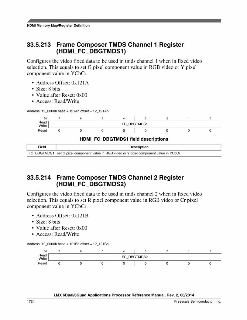
33.5.213 Frame Composer TMDS Channel 1 Register(HDMI_FC_DBGTMDS1)
Configures the video fixed data to be used in tmds channel 1 when in fixed videoselection. This equals to set G pixel component value in RGB video or Y pixelcomponent value in YCbCr.
• Address Offset: 0x121A• Size: 8 bits• Value after Reset: 0x00• Access: Read/Write
Address: 12_0000h base + 121Ah offset = 12_121Ah
Bit 7 6 5 4 3 2 1 0
Read FC_DBGTMDS1WriteReset 0 0 0 0 0 0 0 0
HDMI_FC_DBGTMDS1 field descriptions
Field Description
FC_DBGTMDS1 set G pixel component value in RGB video or Y pixel component value in YCbCr
33.5.214 Frame Composer TMDS Channel 2 Register(HDMI_FC_DBGTMDS2)
Configures the video fixed data to be used in tmds channel 2 when in fixed videoselection. This equals to set R pixel component value in RGB video or Cr pixelcomponent value in YCbCr.
• Address Offset: 0x121B• Size: 8 bits• Value after Reset: 0x00• Access: Read/Write
Address: 12_0000h base + 121Bh offset = 12_121Bh
Bit 7 6 5 4 3 2 1 0
Read FC_DBGTMDS2WriteReset 0 0 0 0 0 0 0 0
HDMI Memory Map/Register Definition
i.MX 6Dual/6Quad Applications Processor Reference Manual, Rev. 2, 06/2014
1724 Freescale Semiconductor, Inc.

HDMI_FC_DBGTMDS2 field descriptions
Field Description
FC_DBGTMDS2 set R pixel component value in RGB video or Cr pixel component value in YCbCr
33.5.215 PHY Configuration Register (HDMI_PHY_CONF0)This register holds the power down, data enable polarity and interface control of theHDMI Source PHY control. For more information, refer to the DesignWare Cores HDMITX PHY Databook.
• Address Offset: 0x3000• Size: 8 bits• Value after Reset: 0x06• Access: Read/Write
Address: 12_0000h base + 3000h offset = 12_3000h
Bit 7 6 5 4
Read PDZ ENTMDS sparectrl gen2_pddqWriteReset 0 0 0 0
Bit 3 2 1 0
Read gen2_txpwron gen2_enhpdrxsense seldataenpol seldipifWriteReset 0 1 1 0
HDMI_PHY_CONF0 field descriptions
Field Description
7PDZ
Power-down enable (active low 0b).
Value after Reset: 0b
6ENTMDS
Enable TMDS drivers, bias, and TMDS digital logic.
Value after Reset: 0b
5sparectrl
Reserved. Spare pin control.
Value after Reset: 0b
4gen2_pddq
PHY_Gen2 PDDQ signal
Value after Reset: 0b
3gen2_txpwron
PHY_Gen2 TXPWRON signal
Value after Reset: 0b
2gen2_
enhpdrxsense
PHY_Gen2 ENHPDRXSENSE signal
Value after Reset: 1b
1seldataenpol
Select data enable polarity.
Value after Reset: 1b
Table continues on the next page...
Chapter 33 HDMI Transmitter (HDMI)
i.MX 6Dual/6Quad Applications Processor Reference Manual, Rev. 2, 06/2014
Freescale Semiconductor, Inc. 1725
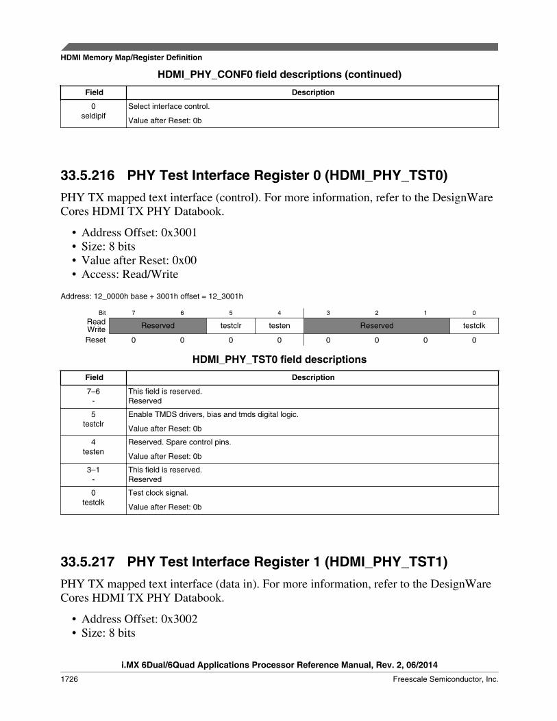
HDMI_PHY_CONF0 field descriptions (continued)
Field Description
0seldipif
Select interface control.
Value after Reset: 0b
33.5.216 PHY Test Interface Register 0 (HDMI_PHY_TST0)PHY TX mapped text interface (control). For more information, refer to the DesignWareCores HDMI TX PHY Databook.
• Address Offset: 0x3001• Size: 8 bits• Value after Reset: 0x00• Access: Read/Write
Address: 12_0000h base + 3001h offset = 12_3001h
Bit 7 6 5 4 3 2 1 0
Read Reserved testclr testen Reserved testclkWriteReset 0 0 0 0 0 0 0 0
HDMI_PHY_TST0 field descriptions
Field Description
7–6-
This field is reserved.Reserved
5testclr
Enable TMDS drivers, bias and tmds digital logic.
Value after Reset: 0b
4testen
Reserved. Spare control pins.
Value after Reset: 0b
3–1-
This field is reserved.Reserved
0testclk
Test clock signal.
Value after Reset: 0b
33.5.217 PHY Test Interface Register 1 (HDMI_PHY_TST1)PHY TX mapped text interface (data in). For more information, refer to the DesignWareCores HDMI TX PHY Databook.
• Address Offset: 0x3002• Size: 8 bits
HDMI Memory Map/Register Definition
i.MX 6Dual/6Quad Applications Processor Reference Manual, Rev. 2, 06/2014
1726 Freescale Semiconductor, Inc.
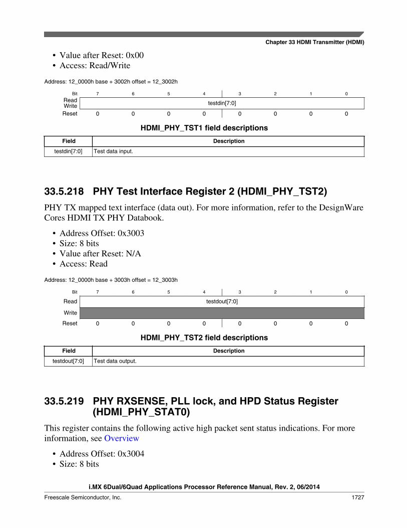
• Value after Reset: 0x00• Access: Read/Write
Address: 12_0000h base + 3002h offset = 12_3002h
Bit 7 6 5 4 3 2 1 0
Read testdin[7:0]WriteReset 0 0 0 0 0 0 0 0
HDMI_PHY_TST1 field descriptions
Field Description
testdin[7:0] Test data input.
33.5.218 PHY Test Interface Register 2 (HDMI_PHY_TST2)PHY TX mapped text interface (data out). For more information, refer to the DesignWareCores HDMI TX PHY Databook.
• Address Offset: 0x3003• Size: 8 bits• Value after Reset: N/A• Access: Read
Address: 12_0000h base + 3003h offset = 12_3003h
Bit 7 6 5 4 3 2 1 0
Read testdout[7:0]
Write
Reset 0 0 0 0 0 0 0 0
HDMI_PHY_TST2 field descriptions
Field Description
testdout[7:0] Test data output.
33.5.219 PHY RXSENSE, PLL lock, and HPD Status Register(HDMI_PHY_STAT0)
This register contains the following active high packet sent status indications. For moreinformation, see Overview
• Address Offset: 0x3004• Size: 8 bits
Chapter 33 HDMI Transmitter (HDMI)
i.MX 6Dual/6Quad Applications Processor Reference Manual, Rev. 2, 06/2014
Freescale Semiconductor, Inc. 1727

• Value after Reset: 0x00• Access: Read
Address: 12_0000h base + 3004h offset = 12_3004h
Bit 7 6 5 4
Read RX_SENSE3 RX_SENSE2 RX_SENSE1 RX_SENSE0
Write
Reset 0 0 0 0
Bit 3 2 1 0
ReadReserved
HPD TX_PHY_LOCK
Write
Reset 0 0 0 0
HDMI_PHY_STAT0 field descriptions
Field Description
7RX_SENSE3
Status bit. TX PHY RX_SENSE indication for TMDS CLK driver. User may need to mask or changepolarity of this interrupt after it has became active.
6RX_SENSE2
Status bit. TX PHY RX_SENSE indication for TMDS channel 2 driver. User may need to mask or changepolarity of this interrupt after it has became active.
5RX_SENSE1
Status bit. TX PHY RX_SENSE indication for TMDS channel 1 driver. User may need to mask or changepolarity of this interrupt after it has became active.
4RX_SENSE0
Status bit. TX PHY RX_SENSE indication for TMDS channel 0 driver. User may need to mask or changepolarity of this interrupt after it has became active.
3–2-
This field is reserved.Reserved
1HPD
Status bit. HDMI Hot Plug Detect indication. User may need to mask or change polarity of this interruptafter it has became active.
0TX_PHY_LOCK
Status bit. TX PHY PLL lock indication. Please refer to PHY datasheet for more information. User mayneed to mask or change polarity of this interrupt after it has became active.
33.5.220 PHY RXSENSE, PLL lock, and HPD Interrupt Register(HDMI_PHY_INT0)
This register contains the interrupt indication of the PHY_STAT0 status interrupts.Interrupt generation is accomplished in the following way:
interrupt = (mask == 1'b0) && (polarity == status);
All this interrupts are forwarded to the Interrupt Handler sticky bit registers and afterORed to a single main interrupt line to micro controller. Assertion of this interruptimplies that data related with the corresponding packet has been sent through the HDMIinterface.
• Address Offset: 0x3005
HDMI Memory Map/Register Definition
i.MX 6Dual/6Quad Applications Processor Reference Manual, Rev. 2, 06/2014
1728 Freescale Semiconductor, Inc.

• Size: 8 bits• Value after Reset: 0x00• Access: Read
Address: 12_0000h base + 3005h offset = 12_3005h
Bit 7 6 5 4
Read RX_SENSE3 RX_SENSE2 RX_SENSE1 RX_SENSE0
Write
Reset 0 0 0 0
Bit 3 2 1 0
ReadReserved
HPD TX_PHY_LOCK
Write
Reset 0 0 0 0
HDMI_PHY_INT0 field descriptions
Field Description
7RX_SENSE3
Interrupt indication bit
TX PHY RX_SENSE indication interrupt for TMDS CLK driver.
6RX_SENSE2
Interrupt indication bit
TX PHY RX_SENSE indication interrupt for TMDS channel 2 driver.
5RX_SENSE1
Interrupt indication bit
TX PHY RX_SENSE indication interrupt for TMDS channel 1 driver.
4RX_SENSE0
Interrupt indication bit
TX PHY RX_SENSE indication interrupt for TMDS channel 0 driver.
3–2-
This field is reserved.Reserved
1HPD
Interrupt indication bit
HDMI Hot Plug Detect indication interrupt.
0TX_PHY_LOCK
Interrupt indication bit
TX PHY PLL lock indication interrupt.
33.5.221 PHY RXSENSE, PLL lock, and HPD Mask Register(HDMI_PHY_MASK0)
Mask register for generation of PHY_INT0 interrupts.
• Address Offset: 0x3006• Size: 8 bits• Value after Reset: 0x00• Access: Read/Write
Chapter 33 HDMI Transmitter (HDMI)
i.MX 6Dual/6Quad Applications Processor Reference Manual, Rev. 2, 06/2014
Freescale Semiconductor, Inc. 1729
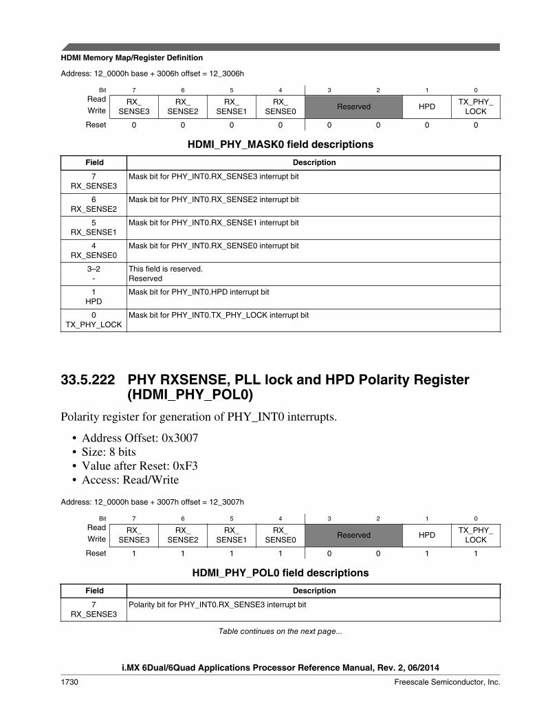
Address: 12_0000h base + 3006h offset = 12_3006h
Bit 7 6 5 4 3 2 1 0
Read RX_SENSE3
RX_SENSE2
RX_SENSE1
RX_SENSE0
Reserved HPDTX_PHY_
LOCKWrite
Reset 0 0 0 0 0 0 0 0
HDMI_PHY_MASK0 field descriptions
Field Description
7RX_SENSE3
Mask bit for PHY_INT0.RX_SENSE3 interrupt bit
6RX_SENSE2
Mask bit for PHY_INT0.RX_SENSE2 interrupt bit
5RX_SENSE1
Mask bit for PHY_INT0.RX_SENSE1 interrupt bit
4RX_SENSE0
Mask bit for PHY_INT0.RX_SENSE0 interrupt bit
3–2-
This field is reserved.Reserved
1HPD
Mask bit for PHY_INT0.HPD interrupt bit
0TX_PHY_LOCK
Mask bit for PHY_INT0.TX_PHY_LOCK interrupt bit
33.5.222 PHY RXSENSE, PLL lock and HPD Polarity Register(HDMI_PHY_POL0)
Polarity register for generation of PHY_INT0 interrupts.
• Address Offset: 0x3007• Size: 8 bits• Value after Reset: 0xF3• Access: Read/Write
Address: 12_0000h base + 3007h offset = 12_3007h
Bit 7 6 5 4 3 2 1 0
Read RX_SENSE3
RX_SENSE2
RX_SENSE1
RX_SENSE0
Reserved HPDTX_PHY_
LOCKWrite
Reset 1 1 1 1 0 0 1 1
HDMI_PHY_POL0 field descriptions
Field Description
7RX_SENSE3
Polarity bit for PHY_INT0.RX_SENSE3 interrupt bit
Table continues on the next page...
HDMI Memory Map/Register Definition
i.MX 6Dual/6Quad Applications Processor Reference Manual, Rev. 2, 06/2014
1730 Freescale Semiconductor, Inc.

HDMI_PHY_POL0 field descriptions (continued)
Field Description
6RX_SENSE2
Polarity bit for PHY_INT0.RX_SENSE2 interrupt bit
5RX_SENSE1
Polarity bit for PHY_INT0.RX_SENSE1 interrupt bit
4RX_SENSE0
Polarity bit for PHY_INT0.RX_SENSE0 interrupt bit
3–2-
This field is reserved.Reserved
1HPD
Polarity bit for PHY_INT0.HPD interrupt bit
0TX_PHY_LOCK
Polarity bit for PHY_INT0.TX_PHY_LOCK interrupt bit
33.5.223 PHY I2C Slave Address Configuration Register(HDMI_PHY_I2CM_SLAVE_ADDR)
This register writes the slave address of the I2C Master PHY.
• Address Offset: 0x3020• Size: 8 bits• Value after Reset: 0x00• Access: Read/Write
Address: 12_0000h base + 3020h offset = 12_3020h
Bit 7 6 5 4 3 2 1 0
Read Reserved -WriteReset 0 0 0 0 0 0 0 0
HDMI_PHY_I2CM_SLAVE_ADDR field descriptions
Field Description
7-
This field is reserved.Reserved
- Slave address to be sent during read and write operations. The PHY Gen2 slave address is: 7'h69
The HEAC PHY slave address is: 7'h49
33.5.224 PHY I2C Address Configuration Register(HDMI_PHY_I2CM_ADDRESS_ADDR)
This register writes the address for read and writer operations.
Chapter 33 HDMI Transmitter (HDMI)
i.MX 6Dual/6Quad Applications Processor Reference Manual, Rev. 2, 06/2014
Freescale Semiconductor, Inc. 1731
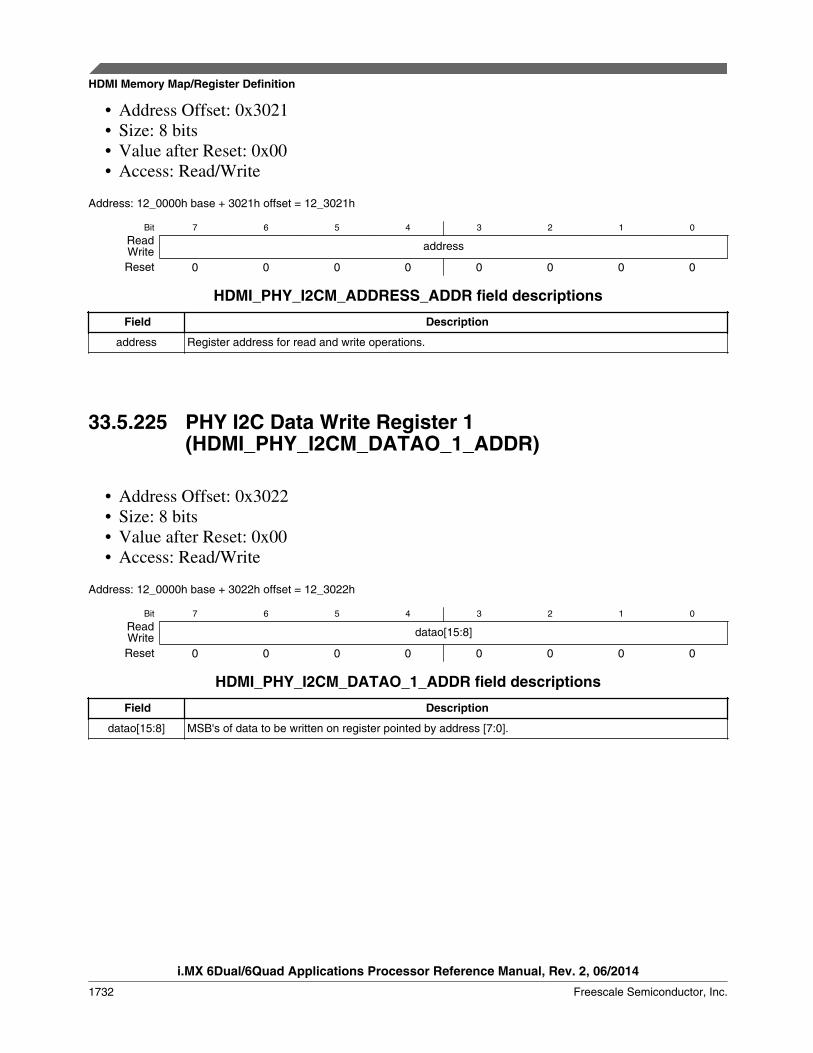
• Address Offset: 0x3021• Size: 8 bits• Value after Reset: 0x00• Access: Read/Write
Address: 12_0000h base + 3021h offset = 12_3021h
Bit 7 6 5 4 3 2 1 0
Read addressWriteReset 0 0 0 0 0 0 0 0
HDMI_PHY_I2CM_ADDRESS_ADDR field descriptions
Field Description
address Register address for read and write operations.
33.5.225 PHY I2C Data Write Register 1(HDMI_PHY_I2CM_DATAO_1_ADDR)
• Address Offset: 0x3022• Size: 8 bits• Value after Reset: 0x00• Access: Read/Write
Address: 12_0000h base + 3022h offset = 12_3022h
Bit 7 6 5 4 3 2 1 0
Read datao[15:8]WriteReset 0 0 0 0 0 0 0 0
HDMI_PHY_I2CM_DATAO_1_ADDR field descriptions
Field Description
datao[15:8] MSB's of data to be written on register pointed by address [7:0].
HDMI Memory Map/Register Definition
i.MX 6Dual/6Quad Applications Processor Reference Manual, Rev. 2, 06/2014
1732 Freescale Semiconductor, Inc.

33.5.226 PHY I2C Data Write Register 0(HDMI_PHY_I2CM_DATAO_0_ADDR)
• Address Offset: 0x3023• Size: 8 bits• Value after Reset: 0x00• Access: Read/Write
Address: 12_0000h base + 3023h offset = 12_3023h
Bit 7 6 5 4 3 2 1 0
Read datao[7:0]WriteReset 0 0 0 0 0 0 0 0
HDMI_PHY_I2CM_DATAO_0_ADDR field descriptions
Field Description
datao[7:0] LSB's of data to be written on register pointed by address [7:0].
33.5.227 PHY I2C Data Read Register 1(HDMI_PHY_I2CM_DATAI_1_ADDR)
• Address Offset: 0x3024• Size: 8 bits• Value after Reset: 0x00• Access: Read
Address: 12_0000h base + 3024h offset = 12_3024h
Bit 7 6 5 4 3 2 1 0
Read datai[15:8]
Write
Reset 0 0 0 0 0 0 0 0
HDMI_PHY_I2CM_DATAI_1_ADDR field descriptions
Field Description
datai[15:8] MSB's of data read from the register pointed by address [7:0].
Chapter 33 HDMI Transmitter (HDMI)
i.MX 6Dual/6Quad Applications Processor Reference Manual, Rev. 2, 06/2014
Freescale Semiconductor, Inc. 1733

33.5.228 PHY I2C Data Read Register 0(HDMI_PHY_I2CM_DATAI_0_ADDR)
• Address Offset: 0x3025• Size: 8 bits• Value after Reset: 0x00• Access: Read
Address: 12_0000h base + 3025h offset = 12_3025h
Bit 7 6 5 4 3 2 1 0
Read datai[7:0]WriteReset 0 0 0 0 0 0 0 0
HDMI_PHY_I2CM_DATAI_0_ADDR field descriptions
Field Description
datai[7:0] LSB's of data read from the register pointed by address [7:0].
33.5.229 PHY I2C Read/Write Operation(HDMI_PHY_I2CM_OPERATION_ADDR)
This register requests read and write operations from the I2C Master PHY. This registercan only be written; reading this register always results in 00h. Writing 1'b1simultaneously to read and write requests is considered a read request.
• Address Offset: 0x3026• Size: 8 bits• Value after Reset: 0x00• Access: Write
Address: 12_0000h base + 3026h offset = 12_3026h
Bit 7 6 5 4 3 2 1 0
ReadReserved Reserved
Write write read
Reset 0 0 0 0 0 0 0 0
HDMI Memory Map/Register Definition
i.MX 6Dual/6Quad Applications Processor Reference Manual, Rev. 2, 06/2014
1734 Freescale Semiconductor, Inc.
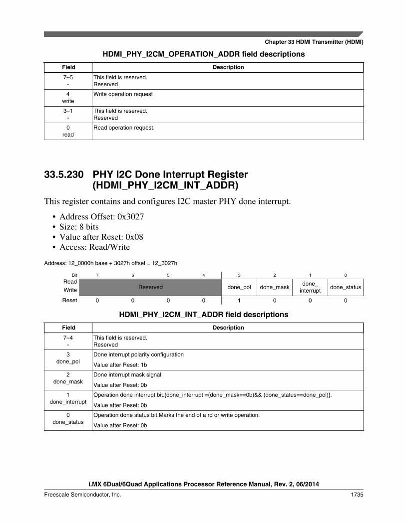
HDMI_PHY_I2CM_OPERATION_ADDR field descriptions
Field Description
7–5-
This field is reserved.Reserved
4write
Write operation request
3–1-
This field is reserved.Reserved
0read
Read operation request.
33.5.230 PHY I2C Done Interrupt Register(HDMI_PHY_I2CM_INT_ADDR)
This register contains and configures I2C master PHY done interrupt.
• Address Offset: 0x3027• Size: 8 bits• Value after Reset: 0x08• Access: Read/Write
Address: 12_0000h base + 3027h offset = 12_3027h
Bit 7 6 5 4 3 2 1 0
ReadReserved done_pol done_mask
done_interrupt
done_statusWrite
Reset 0 0 0 0 1 0 0 0
HDMI_PHY_I2CM_INT_ADDR field descriptions
Field Description
7–4-
This field is reserved.Reserved
3done_pol
Done interrupt polarity configuration
Value after Reset: 1b
2done_mask
Done interrupt mask signal
Value after Reset: 0b
1done_interrupt
Operation done interrupt bit.{done_interrupt =(done_mask==0b)&& (done_status==done_pol)}.
Value after Reset: 0b
0done_status
Operation done status bit.Marks the end of a rd or write operation.
Value after Reset: 0b
Chapter 33 HDMI Transmitter (HDMI)
i.MX 6Dual/6Quad Applications Processor Reference Manual, Rev. 2, 06/2014
Freescale Semiconductor, Inc. 1735
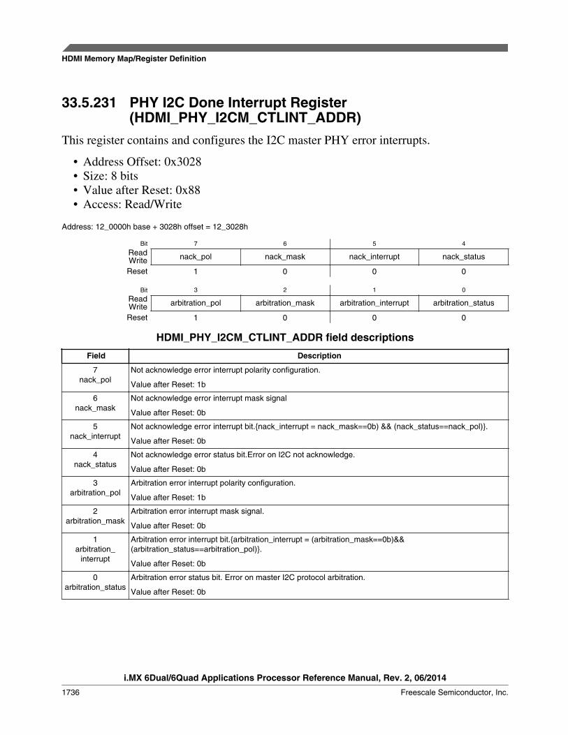
33.5.231 PHY I2C Done Interrupt Register(HDMI_PHY_I2CM_CTLINT_ADDR)
This register contains and configures the I2C master PHY error interrupts.
• Address Offset: 0x3028• Size: 8 bits• Value after Reset: 0x88• Access: Read/Write
Address: 12_0000h base + 3028h offset = 12_3028h
Bit 7 6 5 4
Read nack_pol nack_mask nack_interrupt nack_statusWriteReset 1 0 0 0
Bit 3 2 1 0
Read arbitration_pol arbitration_mask arbitration_interrupt arbitration_statusWriteReset 1 0 0 0
HDMI_PHY_I2CM_CTLINT_ADDR field descriptions
Field Description
7nack_pol
Not acknowledge error interrupt polarity configuration.
Value after Reset: 1b
6nack_mask
Not acknowledge error interrupt mask signal
Value after Reset: 0b
5nack_interrupt
Not acknowledge error interrupt bit.{nack_interrupt = nack_mask==0b) && (nack_status==nack_pol)}.
Value after Reset: 0b
4nack_status
Not acknowledge error status bit.Error on I2C not acknowledge.
Value after Reset: 0b
3arbitration_pol
Arbitration error interrupt polarity configuration.
Value after Reset: 1b
2arbitration_mask
Arbitration error interrupt mask signal.
Value after Reset: 0b
1arbitration_
interrupt
Arbitration error interrupt bit.{arbitration_interrupt = (arbitration_mask==0b)&&(arbitration_status==arbitration_pol)}.
Value after Reset: 0b
0arbitration_status
Arbitration error status bit. Error on master I2C protocol arbitration.
Value after Reset: 0b
HDMI Memory Map/Register Definition
i.MX 6Dual/6Quad Applications Processor Reference Manual, Rev. 2, 06/2014
1736 Freescale Semiconductor, Inc.

33.5.232 PHY I2C Speed Control Register(HDMI_PHY_I2CM_DIV_ADDR)
This register wets the I2C Master PHY to work in either Fast or Standard mode.
• Address Offset: 0x3029• Size: 8 bits• Value after Reset: 0x0B• Access: Read/Write
Address: 12_0000h base + 3029h offset = 12_3029h
Bit 7 6 5 4 3 2 1 0
Read Reserved fast_modeWriteReset 0 0 0 0 1 0 1 1
HDMI_PHY_I2CM_DIV_ADDR field descriptions
Field Description
7–4-
This field is reserved.Reserved
fast_mode Sets the I2C Master to work in Fast Mode or Standard Mode
(x implies that it can take any value)
Value after Reset: 1011b
1xxxb Fast Mode
0xxxb Standard Mode
33.5.233 PHY I2C Software Reset Register(HDMI_PHY_I2CM_SOFTRSTZ_ADDR)
This register sets the I2C Master PHY software reset.
• Address Offset: 0x302A• Size: 8 bits• Value after Reset: 0x01• Access: Read/Write
The following *CNT registers must be set before any I2C bus transaction can take placeto ensure proper I/O timing.
The following are the I2C Master SCL clock settings:
• SS: Standard Speed
Chapter 33 HDMI Transmitter (HDMI)
i.MX 6Dual/6Quad Applications Processor Reference Manual, Rev. 2, 06/2014
Freescale Semiconductor, Inc. 1737
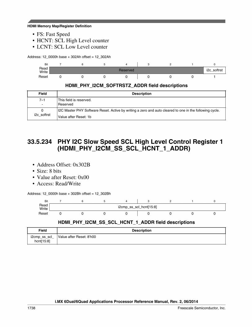
• FS: Fast Speed• HCNT: SCL High Level counter• LCNT: SCL Low Level counter
Address: 12_0000h base + 302Ah offset = 12_302Ah
Bit 7 6 5 4 3 2 1 0
Read Reserved i2c_softrstWriteReset 0 0 0 0 0 0 0 1
HDMI_PHY_I2CM_SOFTRSTZ_ADDR field descriptions
Field Description
7–1-
This field is reserved.Reserved
0i2c_softrst
I2C Master PHY Software Reset. Active by writing a zero and auto cleared to one in the following cycle.
Value after Reset: 1b
33.5.234 PHY I2C Slow Speed SCL High Level Control Register 1(HDMI_PHY_I2CM_SS_SCL_HCNT_1_ADDR)
• Address Offset: 0x302B• Size: 8 bits• Value after Reset: 0x00• Access: Read/Write
Address: 12_0000h base + 302Bh offset = 12_302Bh
Bit 7 6 5 4 3 2 1 0
Read i2cmp_ss_scl_hcnt[15:8]WriteReset 0 0 0 0 0 0 0 0
HDMI_PHY_I2CM_SS_SCL_HCNT_1_ADDR field descriptions
Field Description
i2cmp_ss_scl_hcnt[15:8]
Value after Reset: 8'h00
HDMI Memory Map/Register Definition
i.MX 6Dual/6Quad Applications Processor Reference Manual, Rev. 2, 06/2014
1738 Freescale Semiconductor, Inc.
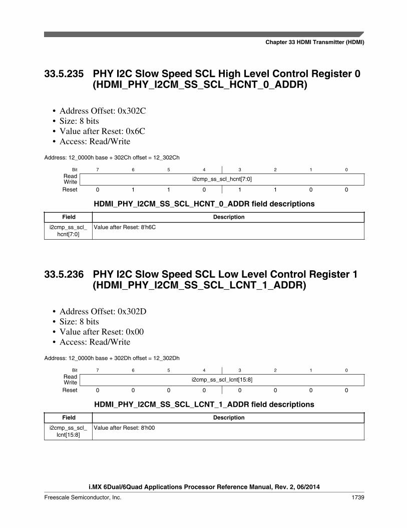
33.5.235 PHY I2C Slow Speed SCL High Level Control Register 0(HDMI_PHY_I2CM_SS_SCL_HCNT_0_ADDR)
• Address Offset: 0x302C• Size: 8 bits• Value after Reset: 0x6C• Access: Read/Write
Address: 12_0000h base + 302Ch offset = 12_302Ch
Bit 7 6 5 4 3 2 1 0
Read i2cmp_ss_scl_hcnt[7:0]WriteReset 0 1 1 0 1 1 0 0
HDMI_PHY_I2CM_SS_SCL_HCNT_0_ADDR field descriptions
Field Description
i2cmp_ss_scl_hcnt[7:0]
Value after Reset: 8'h6C
33.5.236 PHY I2C Slow Speed SCL Low Level Control Register 1(HDMI_PHY_I2CM_SS_SCL_LCNT_1_ADDR)
• Address Offset: 0x302D• Size: 8 bits• Value after Reset: 0x00• Access: Read/Write
Address: 12_0000h base + 302Dh offset = 12_302Dh
Bit 7 6 5 4 3 2 1 0
Read i2cmp_ss_scl_lcnt[15:8]WriteReset 0 0 0 0 0 0 0 0
HDMI_PHY_I2CM_SS_SCL_LCNT_1_ADDR field descriptions
Field Description
i2cmp_ss_scl_lcnt[15:8]
Value after Reset: 8'h00
Chapter 33 HDMI Transmitter (HDMI)
i.MX 6Dual/6Quad Applications Processor Reference Manual, Rev. 2, 06/2014
Freescale Semiconductor, Inc. 1739
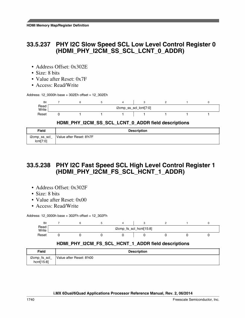
33.5.237 PHY I2C Slow Speed SCL Low Level Control Register 0(HDMI_PHY_I2CM_SS_SCL_LCNT_0_ADDR)
• Address Offset: 0x302E• Size: 8 bits• Value after Reset: 0x7F• Access: Read/Write
Address: 12_0000h base + 302Eh offset = 12_302Eh
Bit 7 6 5 4 3 2 1 0
Read i2cmp_ss_scl_lcnt[7:0]WriteReset 0 1 1 1 1 1 1 1
HDMI_PHY_I2CM_SS_SCL_LCNT_0_ADDR field descriptions
Field Description
i2cmp_ss_scl_lcnt[7:0]
Value after Reset: 8'h7F
33.5.238 PHY I2C Fast Speed SCL High Level Control Register 1(HDMI_PHY_I2CM_FS_SCL_HCNT_1_ADDR)
• Address Offset: 0x302F• Size: 8 bits• Value after Reset: 0x00• Access: Read/Write
Address: 12_0000h base + 302Fh offset = 12_302Fh
Bit 7 6 5 4 3 2 1 0
Read i2cmp_fs_scl_hcnt[15:8]WriteReset 0 0 0 0 0 0 0 0
HDMI_PHY_I2CM_FS_SCL_HCNT_1_ADDR field descriptions
Field Description
i2cmp_fs_scl_hcnt[15:8]
Value after Reset: 8'h00
HDMI Memory Map/Register Definition
i.MX 6Dual/6Quad Applications Processor Reference Manual, Rev. 2, 06/2014
1740 Freescale Semiconductor, Inc.

33.5.239 PHY I2C Fast Speed SCL High Level Control Register 0(HDMI_PHY_I2CM_FS_SCL_HCNT_0_ADDR)
• Address Offset: 0x3030• Size: 8 bits• Value after Reset: 0x11• Access: Read/Write
Address: 12_0000h base + 3030h offset = 12_3030h
Bit 7 6 5 4 3 2 1 0
Read i2cmp_fs_scl_hcnt[7:0]WriteReset 0 0 0 1 0 0 0 1
HDMI_PHY_I2CM_FS_SCL_HCNT_0_ADDR field descriptions
Field Description
i2cmp_fs_scl_hcnt[7:0]
Value after Reset: 8'h11
33.5.240 PHY I2C Fast Speed SCL Low Level Control Register 1(HDMI_PHY_I2CM_FS_SCL_LCNT_1_ADDR)
• Address Offset: 0x3031• Size: 8 bits• Value after Reset: 0x00• Access: Read/Write
Address: 12_0000h base + 3031h offset = 12_3031h
Bit 7 6 5 4 3 2 1 0
Read i2cmp_fs_scl_lcnt[15:8]WriteReset 0 0 0 0 0 0 0 0
HDMI_PHY_I2CM_FS_SCL_LCNT_1_ADDR field descriptions
Field Description
i2cmp_fs_scl_lcnt[15:8]
Value after Reset: 8'h00
Chapter 33 HDMI Transmitter (HDMI)
i.MX 6Dual/6Quad Applications Processor Reference Manual, Rev. 2, 06/2014
Freescale Semiconductor, Inc. 1741

33.5.241 PHY I2C Fast Speed SCL Low Level Control Register 0(HDMI_PHY_I2CM_FS_SCL_LCNT_0_ADDR)
• Address Offset: 0x3032• Size: 8 bits• Value after Reset: 0x24• Access: Read/Write
Address: 12_0000h base + 3032h offset = 12_3032h
Bit 7 6 5 4 3 2 1 0
Read i2cmp_fs_scl_lcnt[7:0]WriteReset 0 0 1 0 0 1 0 0
HDMI_PHY_I2CM_FS_SCL_LCNT_0_ADDR field descriptions
Field Description
i2cmp_fs_scl_lcnt[7:0]
Value after Reset: 8'h24
33.5.242 Audio Clock Regenerator N Value Register 1(HDMI_AUD_N1)
For N expected values, refer to the HDMI 1.4a specification.
• Address Offset: 0x3200• Size: 8 bits• Value after Reset: 0x00• Access: Read/Write
Address: 12_0000h base + 3200h offset = 12_3200h
Bit 7 6 5 4 3 2 1 0
Read AudN[7:0]WriteReset 0 0 0 0 0 0 0 0
HDMI_AUD_N1 field descriptions
Field Description
AudN[7:0] HDMI Audio Clock Regenerator N value
HDMI Memory Map/Register Definition
i.MX 6Dual/6Quad Applications Processor Reference Manual, Rev. 2, 06/2014
1742 Freescale Semiconductor, Inc.

33.5.243 Audio Clock Regenerator N Value Register 2(HDMI_AUD_N2)
For N expected values, refer to the HDMI 1.4a specification.
• Address Offset: 0x3201• Size: 8 bits• Value after Reset: 0x00• Access: Read/Write
Address: 12_0000h base + 3201h offset = 12_3201h
Bit 7 6 5 4 3 2 1 0
Read AudN[15:8]WriteReset 0 0 0 0 0 0 0 0
HDMI_AUD_N2 field descriptions
Field Description
AudN[15:8] HDMI Audio Clock Regenerator N value
33.5.244 Audio Clock Regenerator N Value Register 3(HDMI_AUD_N3)
For N expected values, refer to the HDMI 1.4a specification.
• Address Offset: 0x3202• Size: 8 bits• Value after Reset: 0x00• Access: Read/Write
Address: 12_0000h base + 3202h offset = 12_3202h
Bit 7 6 5 4 3 2 1 0
Read Reserved AudN[19:16]WriteReset 0 0 0 0 0 0 0 0
HDMI_AUD_N3 field descriptions
Field Description
7–4-
This field is reserved.Reserved
AudN[19:16] HDMI Audio Clock Regenerator N value
Chapter 33 HDMI Transmitter (HDMI)
i.MX 6Dual/6Quad Applications Processor Reference Manual, Rev. 2, 06/2014
Freescale Semiconductor, Inc. 1743

33.5.245 AUD_CTS1 (HDMI_AUD_CTS1)For CTS expected values, refer to the HDMI 1.4a specification.
• Address Offset: 0x3203• Size: 8 bits• Value after Reset: 0x00• Access: Read/Write
Address: 12_0000h base + 3203h offset = 12_3203h
Bit 7 6 5 4 3 2 1 0
Read audCTS[7:0]WriteReset 0 0 0 0 0 0 0 0
HDMI_AUD_CTS1 field descriptions
Field Description
audCTS[7:0] HDMI Audio Clock Regenerator CTS calculated value. This value can be manually set using theCTS_manual (AUD_CTS3) mechanism.
33.5.246 AUD_CTS2 (HDMI_AUD_CTS2)For CTS expected values, refer to the HDMI 1.4a specification.
• Address Offset: 0x3204• Size: 8 bits• Value after Reset: 0x00• Access: Read/Write
Address: 12_0000h base + 3204h offset = 12_3204h
Bit 7 6 5 4 3 2 1 0
Read audCTS[15:8]WriteReset 0 0 0 0 0 0 0 0
HDMI_AUD_CTS2 field descriptions
Field Description
audCTS[15:8] HDMI Audio Clock Regenerator CTS calculated value. This value can be manually set using theCTS_manual (AUD_CTS3) mechanism.
HDMI Memory Map/Register Definition
i.MX 6Dual/6Quad Applications Processor Reference Manual, Rev. 2, 06/2014
1744 Freescale Semiconductor, Inc.
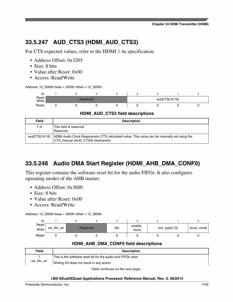
33.5.247 AUD_CTS3 (HDMI_AUD_CTS3)For CTS expected values, refer to the HDMI 1.4a specification.
• Address Offset: 0x3205• Size: 8 bits• Value after Reset: 0x00• Access: Read/Write
Address: 12_0000h base + 3205h offset = 12_3205h
Bit 7 6 5 4 3 2 1 0
Read Reserved audCTS[19:16]WriteReset 0 0 0 0 0 0 0 0
HDMI_AUD_CTS3 field descriptions
Field Description
7–4-
This field is reserved.Reserved
audCTS[19:16] HDMI Audio Clock Regenerator CTS calculated value. This value can be manually set using theCTS_manual (AUD_CTS3) mechanism.
33.5.248 Audio DMA Start Register (HDMI_AHB_DMA_CONF0)This register contains the software reset bit for the audio FIFOs. It also configuresoperating modes of the AHB master.
• Address Offset: 0x3600• Size: 8 bits• Value after Reset: 0x00• Access: Read/Write
Address: 12_0000h base + 3600h offset = 12_3600h
Bit 7 6 5 4 3 2 1 0
Readsw_fifo_rst Reserved hbr
enable_hlock
incr_type[1:0] burst_modeWrite
Reset 0 0 0 0 0 0 0 0
HDMI_AHB_DMA_CONF0 field descriptions
Field Description
7sw_fifo_rst
This is the software reset bit for the audio and FIFOs clear.
Writing 0'b does not result in any action.
Table continues on the next page...
Chapter 33 HDMI Transmitter (HDMI)
i.MX 6Dual/6Quad Applications Processor Reference Manual, Rev. 2, 06/2014
Freescale Semiconductor, Inc. 1745

HDMI_AHB_DMA_CONF0 field descriptions (continued)
Field DescriptionWriting 1'b to this register resets all audio FIFOs.
Reading from this register always returns 0'b.
6–5-
This field is reserved.Reserved
4hbr
HBR packets enable.
The HDMI TX sends the HBR packets. This bit is enabled when the audio frequency is higher than 192KHz. If this bit is enabled, the number of channels configured in AHB_DMA_CONF1 is always 8.
3enable_hlock
Enable request of locked burst AHB mechanism.
1 Enables the usage of ohlock for master request to arbiter of a locked complete burst.\0 Disables request of locked burst AHB mechanism
2–1incr_type[1:0]
Forced size burst mode.
00 Corresponds to INCR4 fixed four beat incremental AHB burst mode. Only valid when burst_mode ishigh.
01 Corresponds to INCR8 fixed eight beat incremental AHB burst mode. Only valid when burst_mode ishigh.
10 Corresponds to INCR16 fixed 16 beat incremental AHB burst mode. Only valid when burst_mode ishigh.
11 Corresponds to INCR16 fixed 16 beat incremental AHB burst mode. Only valid when burst_mode ishigh.
0burst_mode
Burst mode bit
1 Forces the burst mode to be fixed beat incremental burst mode designated by the incr_type[1:0]signal.
0 Normal operation is unspecified length incremental burst. It corresponds to INCR AHB burst mode.
33.5.249 AHB_DMA_START (HDMI_AHB_DMA_START)The data_ buffer_ready bit field signals the AHB audio DMA to start accessing systemmemory in order to fetch data samples to store in the FIFO. After the operation starts, anew request for a DMA start is ignored until the DMA is stopped or it reaches the endaddress. Only in one of these situations will a new start request be acknowledged.
The first DMA burst request after data_buffer_ready configuration uses theinitial_addr[31:0] as the ohaddr[31:0] and the MBURSTLENGTH[10:0] =AUDIO_FIFO_DEPTH if AUDIO_FIFO_DEPTH < 1024 or MBURSTLENGTH[10:0]= 1024 if AUDIO_FIFO_DEPTH >= 1024.
• Address Offset: 0x3601• Size: 8 bits• Value after Reset: 0x00• Access: Read/Write
HDMI Memory Map/Register Definition
i.MX 6Dual/6Quad Applications Processor Reference Manual, Rev. 2, 06/2014
1746 Freescale Semiconductor, Inc.

Address: 12_0000h base + 3601h offset = 12_3601h
Bit 7 6 5 4 3 2 1 0
ReadReserved
data_buffer_readyWrite
Reset 0 0 0 0 0 0 0 0
HDMI_AHB_DMA_START field descriptions
Field Description
7–1-
This field is reserved.Reserved
0data_buffer_
ready
Data buffer ready
33.5.250 Audio DMA Stop Register (HDMI_AHB_DMA_STOP)The stop_dma_transaction bit field signals the AHB audio DMA to stop current memoryaccess. After it stops, if a new start DMA operation is requested, the DMA engine restartsthe memory access assuming the initial_addr[31:0] is programmed atAHB_DMA_STRADDR0 to AHB_DMA_STRADDR3.
• Address Offset: 0x3602• Size: 8 bits• Value after Reset: 0x00• Access: Read/Write
Address: 12_0000h base + 3602h offset = 12_3602h
Bit 7 6 5 4 3 2 1 0
ReadReserved
stop_dma_transactionWrite
Reset 0 0 0 0 0 0 0 0
HDMI_AHB_DMA_STOP field descriptions
Field Description
7–1-
This field is reserved.Reserved
0stop_dma_transaction
Stop DMA transaction
Chapter 33 HDMI Transmitter (HDMI)
i.MX 6Dual/6Quad Applications Processor Reference Manual, Rev. 2, 06/2014
Freescale Semiconductor, Inc. 1747

33.5.251 Audio DMA FIFO Threshold Register(HDMI_AHB_DMA_THRSLD)
This register defines the FIFO medium threshold occupation value.
After the AHB master successfully completes a burst transaction, the FIFO may stayremain full until the data fetch interface requests samples. The sample request from theFIFO using the data fetch mechanism drops the number of samples stored in the audioFIFO.
As soon as the number of samples in the FIFO drops lower than the fifo_threshold[7:0],the DMA engine requests a new burst of samples to the AHB master with a size(MBURSTLENGTH[10:0]) equal to AUDIO_FIFO_DEPTH minus fifo_threshold[7:0].
Therefore, the fifo_threshold[7:0] is the medium number of samples that should beavailable in the audio FIFO across the DMA operation.
• Address Offset: 0x3603• Size: 8 bits• Value after Reset: 0x00• Access: Read/Write
Address: 12_0000h base + 3603h offset = 12_3603h
Bit 7 6 5 4 3 2 1 0
Read fifo_threshold[7]WriteReset 0 0 0 0 0 0 0 0
HDMI_AHB_DMA_THRSLD field descriptions
Field Description
fifo_threshold[7] FIFO medium threshold occupation value
33.5.252 Audio DMA Start Address Register 0(HDMI_AHB_DMA_STRADDR0)
These registers define the initial_addr[31:0] used to initiate the DMA burst readtransactions upon data_buffer_ready configuration.
• Address Offset: 0x3604 to 0x3607• Size: 8 bits per register• Value after Reset: 0x00• Access: Read/Write
HDMI Memory Map/Register Definition
i.MX 6Dual/6Quad Applications Processor Reference Manual, Rev. 2, 06/2014
1748 Freescale Semiconductor, Inc.
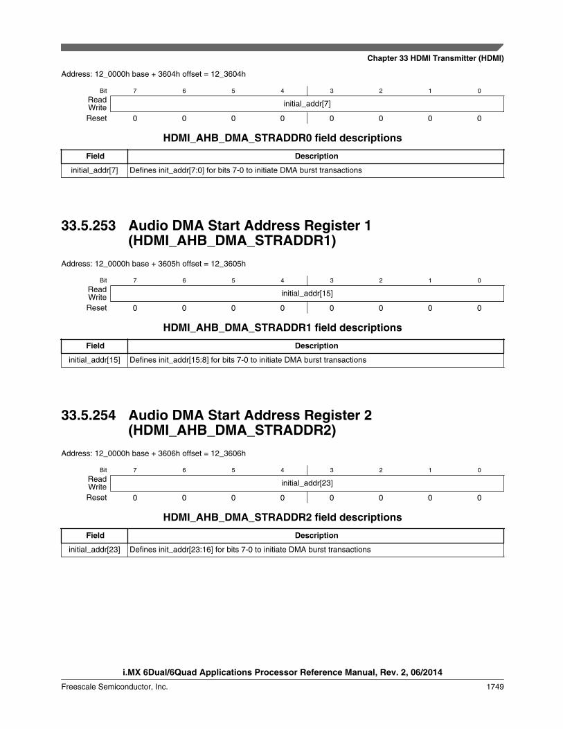
Address: 12_0000h base + 3604h offset = 12_3604h
Bit 7 6 5 4 3 2 1 0
Read initial_addr[7]WriteReset 0 0 0 0 0 0 0 0
HDMI_AHB_DMA_STRADDR0 field descriptions
Field Description
initial_addr[7] Defines init_addr[7:0] for bits 7-0 to initiate DMA burst transactions
33.5.253 Audio DMA Start Address Register 1(HDMI_AHB_DMA_STRADDR1)
Address: 12_0000h base + 3605h offset = 12_3605h
Bit 7 6 5 4 3 2 1 0
Read initial_addr[15]WriteReset 0 0 0 0 0 0 0 0
HDMI_AHB_DMA_STRADDR1 field descriptions
Field Description
initial_addr[15] Defines init_addr[15:8] for bits 7-0 to initiate DMA burst transactions
33.5.254 Audio DMA Start Address Register 2(HDMI_AHB_DMA_STRADDR2)
Address: 12_0000h base + 3606h offset = 12_3606h
Bit 7 6 5 4 3 2 1 0
Read initial_addr[23]WriteReset 0 0 0 0 0 0 0 0
HDMI_AHB_DMA_STRADDR2 field descriptions
Field Description
initial_addr[23] Defines init_addr[23:16] for bits 7-0 to initiate DMA burst transactions
Chapter 33 HDMI Transmitter (HDMI)
i.MX 6Dual/6Quad Applications Processor Reference Manual, Rev. 2, 06/2014
Freescale Semiconductor, Inc. 1749

33.5.255 Audio DMA Start Address Register 3(HDMI_AHB_DMA_STRADDR3)
Address: 12_0000h base + 3607h offset = 12_3607h
Bit 7 6 5 4 3 2 1 0
Read initial_addr[31]WriteReset 0 0 0 0 0 0 0 0
HDMI_AHB_DMA_STRADDR3 field descriptions
Field Description
initial_addr[31] Defines init_addr[31:24] for bits 7-0 to initiate DMA burst transactions
33.5.256 Audio DMA Stop Address Register 0(HDMI_AHB_DMA_STPADDR0)
This registers define the final_addr[31:0] used as the final point to the DMA burst readtransactions.
Upon data_buffer_ready configuration, the DMA engine starts requesting burst readsfrom the external system memory. Each burst read can have a maximum theoreticallength of 1024 words (due to the AMBA AHB specification restriction). As an example,if the first burst transaction of the AHB audio DMA has a length of 16, then the secondburst starts at address ohaddr[31:0] = initial_addr[31:0] + 16 and has a length ofMBURSTLENGTH[10:0] = AUDIO_FIFO_DEPTH - fifo_threshold[7:0].
The DMA engine is responsible for incrementing the burst starting address and definingits corresponding burst length to reach the final_addr[31:0] address. The last burst requestissued by the DMA engine takes into account that it should only request data until thefinal_addr[31:0] address (included) and for that should calculate the correct burst length.
After reaching the final_addr[31:0] address, the done interrupt is active to signalcompletion of DMA operation.
• Address Offset: 0x3608 to 0x360B• Size: 8 bits per register• Value after Reset: 0x00• Access: Read/Write
HDMI Memory Map/Register Definition
i.MX 6Dual/6Quad Applications Processor Reference Manual, Rev. 2, 06/2014
1750 Freescale Semiconductor, Inc.

Address: 12_0000h base + 3608h offset = 12_3608h
Bit 7 6 5 4 3 2 1 0
Read final_addr[7]WriteReset 0 0 0 0 0 0 0 0
HDMI_AHB_DMA_STPADDR0 field descriptions
Field Description
final_addr[7] Defines final_addr[7:0] for bits 7-0 to initiate DMA burst transactions
33.5.257 Audio DMA Stop Address Register 1(HDMI_AHB_DMA_STPADDR1)
Address: 12_0000h base + 3609h offset = 12_3609h
Bit 7 6 5 4 3 2 1 0
Read final_addr[15]WriteReset 0 0 0 0 0 0 0 0
HDMI_AHB_DMA_STPADDR1 field descriptions
Field Description
final_addr[15] Defines final_addr[15:8] for bits 7-0 to initiate DMA burst transactions
33.5.258 Audio DMA Stop Address Register 2(HDMI_AHB_DMA_STPADDR2)
Address: 12_0000h base + 360Ah offset = 12_360Ah
Bit 7 6 5 4 3 2 1 0
Read final_addr[23]WriteReset 0 0 0 0 0 0 0 0
HDMI_AHB_DMA_STPADDR2 field descriptions
Field Description
final_addr[23] Defines final_addr[23:16] for bits 7-0 to initiate DMA burst transactions
Chapter 33 HDMI Transmitter (HDMI)
i.MX 6Dual/6Quad Applications Processor Reference Manual, Rev. 2, 06/2014
Freescale Semiconductor, Inc. 1751
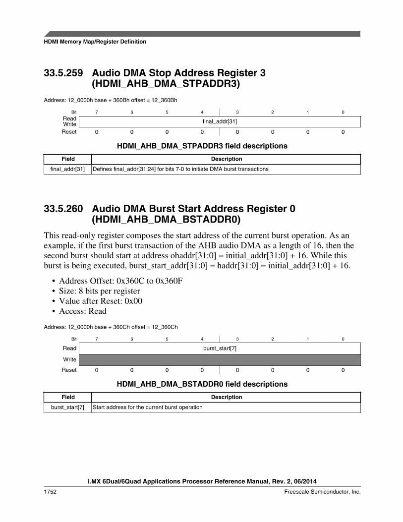
33.5.259 Audio DMA Stop Address Register 3(HDMI_AHB_DMA_STPADDR3)
Address: 12_0000h base + 360Bh offset = 12_360Bh
Bit 7 6 5 4 3 2 1 0
Read final_addr[31]WriteReset 0 0 0 0 0 0 0 0
HDMI_AHB_DMA_STPADDR3 field descriptions
Field Description
final_addr[31] Defines final_addr[31:24] for bits 7-0 to initiate DMA burst transactions
33.5.260 Audio DMA Burst Start Address Register 0(HDMI_AHB_DMA_BSTADDR0)
This read-only register composes the start address of the current burst operation. As anexample, if the first burst transaction of the AHB audio DMA as a length of 16, then thesecond burst should start at address ohaddr[31:0] = initial_addr[31:0] + 16. While thisburst is being executed, burst_start_addr[31:0] = haddr[31:0] = initial_addr[31:0] + 16.
• Address Offset: 0x360C to 0x360F• Size: 8 bits per register• Value after Reset: 0x00• Access: Read
Address: 12_0000h base + 360Ch offset = 12_360Ch
Bit 7 6 5 4 3 2 1 0
Read burst_start[7]
Write
Reset 0 0 0 0 0 0 0 0
HDMI_AHB_DMA_BSTADDR0 field descriptions
Field Description
burst_start[7] Start address for the current burst operation
HDMI Memory Map/Register Definition
i.MX 6Dual/6Quad Applications Processor Reference Manual, Rev. 2, 06/2014
1752 Freescale Semiconductor, Inc.

33.5.261 Audio DMA Burst Start Address Register 1(HDMI_AHB_DMA_BSTADDR1)
Address: 12_0000h base + 360Dh offset = 12_360Dh
Bit 7 6 5 4 3 2 1 0
Read burst_start[15]
Write
Reset 0 0 0 0 0 0 0 0
HDMI_AHB_DMA_BSTADDR1 field descriptions
Field Description
burst_start[15] Start address for the current burst operation
33.5.262 Audio DMA Burst Start Address Register 2(HDMI_AHB_DMA_BSTADDR2)
Address: 12_0000h base + 360Eh offset = 12_360Eh
Bit 7 6 5 4 3 2 1 0
Read burst_start[23]
Write
Reset 0 0 0 0 0 0 0 0
HDMI_AHB_DMA_BSTADDR2 field descriptions
Field Description
burst_start[23] Start address for the current burst operation
33.5.263 Audio DMA Burst Start Address Register 3(HDMI_AHB_DMA_BSTADDR3)
Address: 12_0000h base + 360Fh offset = 12_360Fh
Bit 7 6 5 4 3 2 1 0
Read burst_start[31]
Write
Reset 0 0 0 0 0 0 0 0
Chapter 33 HDMI Transmitter (HDMI)
i.MX 6Dual/6Quad Applications Processor Reference Manual, Rev. 2, 06/2014
Freescale Semiconductor, Inc. 1753

HDMI_AHB_DMA_BSTADDR3 field descriptions
Field Description
burst_start[31] Start address for the current burst operation
33.5.264 Audio DMA Burst Length Register 0(HDMI_AHB_DMA_MBLENGTH0)
These registers hold the length of the current burst operation. As an example, if the firstburst transaction of the AHB audio DMA is a length of 8, then the second burst shouldstart at address ohaddr[31:0] = initial_addr[31:0] + 8. It will also have lengthMBURSTLENGTH[10:0] = AUDIO_FIFO_DEPTH - fifo_threshold[7:0] while thisburst is being executed, MBURSTLENGTH[10:0] = AUDIO_FIFO_DEPTH -fifo_threshold[7:0].
• Address Offset: 0x3610 to 0x3611• Size: 8 bits per register• Value after Reset: 0x00• Access: Read
Address: 12_0000h base + 3610h offset = 12_3610h
Bit 7 6 5 4 3 2 1 0
Read MBURSTLENGTH7
Write
Reset 0 0 0 0 0 0 0 0
HDMI_AHB_DMA_MBLENGTH0 field descriptions
Field Description
MBURSTLENGTH7 Requested burst length
HDMI Memory Map/Register Definition
i.MX 6Dual/6Quad Applications Processor Reference Manual, Rev. 2, 06/2014
1754 Freescale Semiconductor, Inc.

33.5.265 Audio DMA Burst Length Register 1(HDMI_AHB_DMA_MBLENGTH1)
Address: 12_0000h base + 3611h offset = 12_3611h
Bit 7 6 5 4
ReadReserved
Write
Reset 0 0 0 0
Bit 3 2 1 0
ReadReserved
MBURSTLENGTH10 MBURSTLENGTH9 MBURSTLENGTH8
Write
Reset 0 0 0 0
HDMI_AHB_DMA_MBLENGTH1 field descriptions
Field Description
7–3-
This field is reserved.Reserved
2MBURSTLENGTH10
Requested burst length
1MBURSTLENGTH9
Requested burst length
0MBURSTLENGTH8
Requested burst length
33.5.266 Audio DMA Interrupt Status Register(HDMI_AHB_DMA_STAT)
This register contains the status bits of the following interrupts:
• Address Offset: 0x3612• Size: 8 bits per register• Value after Reset: 0x00• Access: Read
Address: 12_0000h base + 3612h offset = 12_3612h
Bit 7 6 5 4
Read statdone statretrysplit statlostownership staterror
Write
Reset 0 0 0 0
Chapter 33 HDMI Transmitter (HDMI)
i.MX 6Dual/6Quad Applications Processor Reference Manual, Rev. 2, 06/2014
Freescale Semiconductor, Inc. 1755

Bit 3 2 1 0
ReadReserved
statthrfifoempty statfifofull statfifoempty
Write
Reset 0 0 0 0
HDMI_AHB_DMA_STAT field descriptions
Field Description
7statdone
Status of DMA end of operation interrupt. Active when DMA engine reaches final_addr[15:0] or whenstop DMA operation is activated.
6statretrysplit
Status of retry/split interrupt. Active when AHB master receives a RETRY or SPLIT response fromslave.
5statlostownership
Status of master lost ownership when in burst transfer. Active when AHB master loses BUS ownershipwithin the course of a burst transfer.
4staterror
Status of error interrupt. Active when slave indicates error through the isresp[1:0].
3-
This field is reserved.Reserved
2statthrfifoempty
Status of audio FIFO empty when audio FIFO has less than four samples.
1statfifofull
Status of audio FIFO full interrupt.
0statfifoempty
Status of audio FIFO empty interrupt.
33.5.267 Audio DMA Interrupt Register (HDMI_AHB_DMA_INT)This register contains the interrupt bits of the following interrupts:
• Address Offset: 0x3613• Size: 8 bits per register• Value after Reset: 0x00• Access: Read
Address: 12_0000h base + 3613h offset = 12_3613h
Bit 7 6 5 4
Read intdone intretrysplit intlostownership interror
Write
Reset 0 0 0 0
Bit 3 2 1 0
ReadReserved
intthrfifoempty intfifofull intfifoempty
Write
Reset 0 0 0 0
HDMI Memory Map/Register Definition
i.MX 6Dual/6Quad Applications Processor Reference Manual, Rev. 2, 06/2014
1756 Freescale Semiconductor, Inc.

HDMI_AHB_DMA_INT field descriptions
Field Description
7intdone
DMA end of operation interrupt. Active when DMA engine reaches final_addr[15:0] or when stop DMAoperation is activated.
6intretrysplit
Retry/split interrupt. Active when AHB master receives a RETRY or SPLIT response from slave.
5intlostownership
Master lost ownership interrupt when in burst transfer. Active when AHB master loses BUS ownershipwithin the course of a burst transfer.
4interror
Error interrupt. Active when slave indicates error through the isresp[1:0].
3-
This field is reserved.Reserved
2intthrfifoempty
Audio FIFO empty interrupt when audio FIFO has less than four samples.
1intfifofull
Audio FIFO full interrupt.
0intfifoempty
Audio FIFO empty interrupt.
33.5.268 Audio DMA Mask Interrupt Register(HDMI_AHB_DMA_MASK)
Mask for each of the interrupts present in the AHB audio DMA module. For usageinformation, see Audio DMA Interrupt Register (HDMI_AHB_DMA_INT) ."
• Address Offset: 0x3614• Size: 8 bits per register• Value after Reset: 0x00• Access: Read/Write
Address: 12_0000h base + 3614h offset = 12_3614h
Bit 7 6 5 4
Read done_mask retrysplit_mask lostownership_mask error_maskWriteReset 0 0 0 0
Bit 3 2 1 0
Read Reserved fifo_thrempty_mask fifo_full_mask fifo_empty_maskWriteReset 0 0 0 0
HDMI_AHB_DMA_MASK field descriptions
Field Description
7done_mask
DMA end of operation interrupt mask. Active when DMA engine reaches final_addr[15:0] or when stopDMA operation is activated.
Table continues on the next page...
Chapter 33 HDMI Transmitter (HDMI)
i.MX 6Dual/6Quad Applications Processor Reference Manual, Rev. 2, 06/2014
Freescale Semiconductor, Inc. 1757
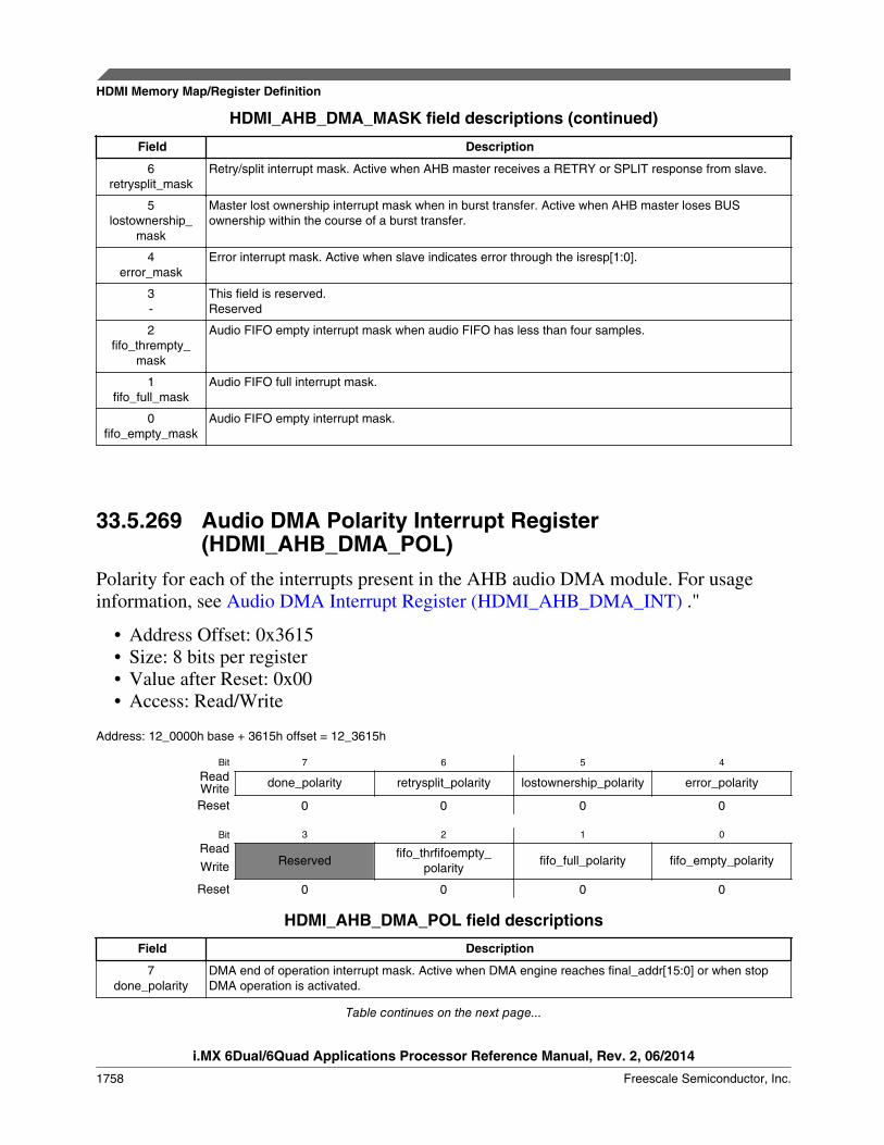
HDMI_AHB_DMA_MASK field descriptions (continued)
Field Description
6retrysplit_mask
Retry/split interrupt mask. Active when AHB master receives a RETRY or SPLIT response from slave.
5lostownership_
mask
Master lost ownership interrupt mask when in burst transfer. Active when AHB master loses BUSownership within the course of a burst transfer.
4error_mask
Error interrupt mask. Active when slave indicates error through the isresp[1:0].
3-
This field is reserved.Reserved
2fifo_thrempty_
mask
Audio FIFO empty interrupt mask when audio FIFO has less than four samples.
1fifo_full_mask
Audio FIFO full interrupt mask.
0fifo_empty_mask
Audio FIFO empty interrupt mask.
33.5.269 Audio DMA Polarity Interrupt Register(HDMI_AHB_DMA_POL)
Polarity for each of the interrupts present in the AHB audio DMA module. For usageinformation, see Audio DMA Interrupt Register (HDMI_AHB_DMA_INT) ."
• Address Offset: 0x3615• Size: 8 bits per register• Value after Reset: 0x00• Access: Read/Write
Address: 12_0000h base + 3615h offset = 12_3615h
Bit 7 6 5 4
Read done_polarity retrysplit_polarity lostownership_polarity error_polarityWriteReset 0 0 0 0
Bit 3 2 1 0
ReadReserved
fifo_thrfifoempty_polarity
fifo_full_polarity fifo_empty_polarityWrite
Reset 0 0 0 0
HDMI_AHB_DMA_POL field descriptions
Field Description
7done_polarity
DMA end of operation interrupt mask. Active when DMA engine reaches final_addr[15:0] or when stopDMA operation is activated.
Table continues on the next page...
HDMI Memory Map/Register Definition
i.MX 6Dual/6Quad Applications Processor Reference Manual, Rev. 2, 06/2014
1758 Freescale Semiconductor, Inc.

HDMI_AHB_DMA_POL field descriptions (continued)
Field Description
6retrysplit_polarity
Retry/split interrupt mask. Active when AHB master receives a RETRY or SPLIT response from slave.
5lostownership_
polarity
Master lost ownership interrupt mask when in burst transfer. Active when AHB master loses BUSownership within the course of a burst transfer.
4error_polarity
Error interrupt mask. Active when slave indicates error through the isresp[1:0].
3-
This field is reserved.Reserved
2fifo_thrfifoempty_
polarity
Audio FIFO empty interrupt mask when audio FIFO has less than four samples.
1fifo_full_polarity
Audio FIFO full interrupt mask.
0fifo_empty_
polarity
Audio FIFO empty interrupt mask.
33.5.270 Audio DMA Channel Enable Configuration Register 1(HDMI_AHB_DMA_CONF1)
• Address Offset: 0x3616• Size: 8 bits• Value after Reset: 0x00• Access: Read/Write
Address: 12_0000h base + 3616h offset = 12_3616h
Bit 7 6 5 4 3 2 1 0
Read CH_IN_EN7 CH_IN_EN6 CH_IN_EN5 CH_IN_EN4 CH_IN_EN3 CH_IN_EN2 CH_IN_EN1 CH_IN_EN0WriteReset 0 0 0 0 0 0 0 0
HDMI_AHB_DMA_CONF1 field descriptions
Field Description
7CH_IN_EN7
Channel 7 enable bit
1 Channel enabled0 Channel disabled
6CH_IN_EN6
Channel 6 enable bit
1 Channel enabled0 Channel disabled
Table continues on the next page...
Chapter 33 HDMI Transmitter (HDMI)
i.MX 6Dual/6Quad Applications Processor Reference Manual, Rev. 2, 06/2014
Freescale Semiconductor, Inc. 1759
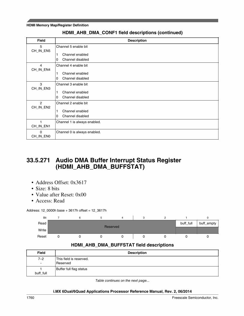
HDMI_AHB_DMA_CONF1 field descriptions (continued)
Field Description
5CH_IN_EN5
Channel 5 enable bit
1 Channel enabled0 Channel disabled
4CH_IN_EN4
Channel 4 enable bit
1 Channel enabled0 Channel disabled
3CH_IN_EN3
Channel 3 enable bit
1 Channel enabled0 Channel disabled
2CH_IN_EN2
Channel 2 enable bit
1 Channel enabled0 Channel disabled
1CH_IN_EN1
Channel 1 is always enabled.
0CH_IN_EN0
Channel 0 is always enabled.
33.5.271 Audio DMA Buffer Interrupt Status Register(HDMI_AHB_DMA_BUFFSTAT)
• Address Offset: 0x3617• Size: 8 bits• Value after Reset: 0x00• Access: Read
Address: 12_0000h base + 3617h offset = 12_3617h
Bit 7 6 5 4 3 2 1 0
ReadReserved
buff_full buff_empty
Write
Reset 0 0 0 0 0 0 0 0
HDMI_AHB_DMA_BUFFSTAT field descriptions
Field Description
7–2-
This field is reserved.Reserved
1buff_full
Buffer full flag status
Table continues on the next page...
HDMI Memory Map/Register Definition
i.MX 6Dual/6Quad Applications Processor Reference Manual, Rev. 2, 06/2014
1760 Freescale Semiconductor, Inc.
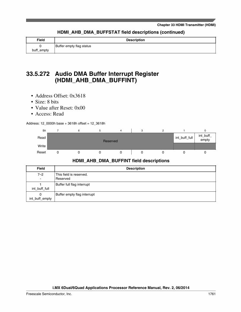
HDMI_AHB_DMA_BUFFSTAT field descriptions (continued)
Field Description
0buff_empty
Buffer empty flag status
33.5.272 Audio DMA Buffer Interrupt Register(HDMI_AHB_DMA_BUFFINT)
• Address Offset: 0x3618• Size: 8 bits• Value after Reset: 0x00• Access: Read
Address: 12_0000h base + 3618h offset = 12_3618h
Bit 7 6 5 4 3 2 1 0
ReadReserved
int_buff_fullint_buff_
empty
Write
Reset 0 0 0 0 0 0 0 0
HDMI_AHB_DMA_BUFFINT field descriptions
Field Description
7–2-
This field is reserved.Reserved
1int_buff_full
Buffer full flag interrupt
0int_buff_empty
Buffer empty flag interrupt
Chapter 33 HDMI Transmitter (HDMI)
i.MX 6Dual/6Quad Applications Processor Reference Manual, Rev. 2, 06/2014
Freescale Semiconductor, Inc. 1761
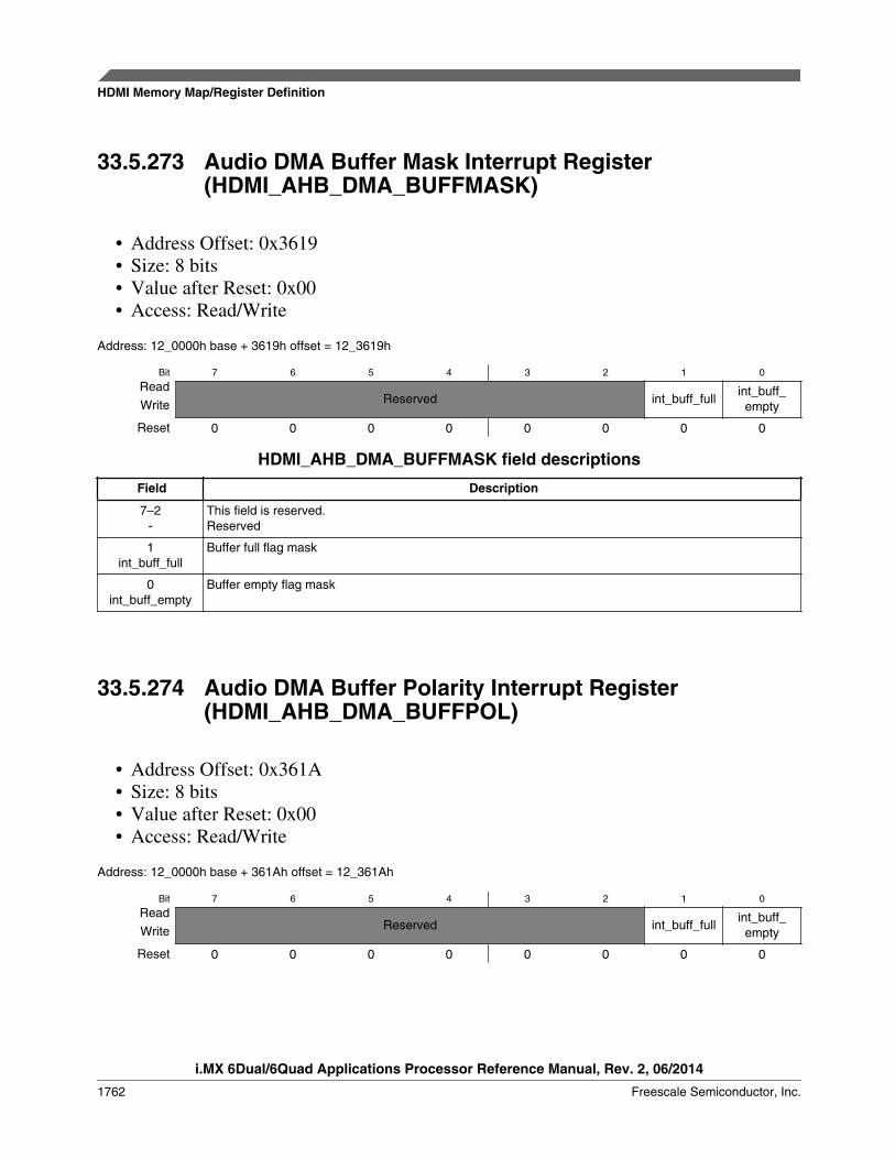
33.5.273 Audio DMA Buffer Mask Interrupt Register(HDMI_AHB_DMA_BUFFMASK)
• Address Offset: 0x3619• Size: 8 bits• Value after Reset: 0x00• Access: Read/Write
Address: 12_0000h base + 3619h offset = 12_3619h
Bit 7 6 5 4 3 2 1 0
ReadReserved int_buff_full
int_buff_emptyWrite
Reset 0 0 0 0 0 0 0 0
HDMI_AHB_DMA_BUFFMASK field descriptions
Field Description
7–2-
This field is reserved.Reserved
1int_buff_full
Buffer full flag mask
0int_buff_empty
Buffer empty flag mask
33.5.274 Audio DMA Buffer Polarity Interrupt Register(HDMI_AHB_DMA_BUFFPOL)
• Address Offset: 0x361A• Size: 8 bits• Value after Reset: 0x00• Access: Read/Write
Address: 12_0000h base + 361Ah offset = 12_361Ah
Bit 7 6 5 4 3 2 1 0
ReadReserved int_buff_full
int_buff_emptyWrite
Reset 0 0 0 0 0 0 0 0
HDMI Memory Map/Register Definition
i.MX 6Dual/6Quad Applications Processor Reference Manual, Rev. 2, 06/2014
1762 Freescale Semiconductor, Inc.

HDMI_AHB_DMA_BUFFPOL field descriptions
Field Description
7–2-
This field is reserved.Reserved
1int_buff_full
Buffer full flag polarity
0int_buff_empty
Buffer empty flag polarity
33.5.275 Main Controller Synchronous Clock Domain DisableRegister (HDMI_MC_CLKDIS)
Main controller synchronous disable control per clock domain. Upon release ofsynchronous disable the corresponding sw reset NRZ request signal, to that domain, istoggled asking to the output for a synchronized active low reset to be generated to thatdomain.
• Address Offset: 0x4001• Size: 8 bits• Value after Reset: 0x00• Access: Read/Write
Address: 12_0000h base + 4001h offset = 12_4001h
Bit 7 6 5 4 3 2 1 0
ReadReserved Reserved
cecclk_disable
cscclk_disable
audclk_disable
prepclk_disable
tmdsclk_disable
pixelclk_disableWrite
Reset 0 0 0 0 0 0 0 0
HDMI_MC_CLKDIS field descriptions
Field Description
7-
This field is reserved.Reserved
6hdcpclk_disable
This field is reserved.Reserved
5cecclk_disable
CEC Engine clock synchronous disable signal.
4cscclk_disable
Color Space Converter clock synchronous disable signal.
3audclk_disable
Audio Sampler clock synchronous disable signal.
2prepclk_disable
Pixel Repetition clock synchronous disable signal.
Table continues on the next page...
Chapter 33 HDMI Transmitter (HDMI)
i.MX 6Dual/6Quad Applications Processor Reference Manual, Rev. 2, 06/2014
Freescale Semiconductor, Inc. 1763
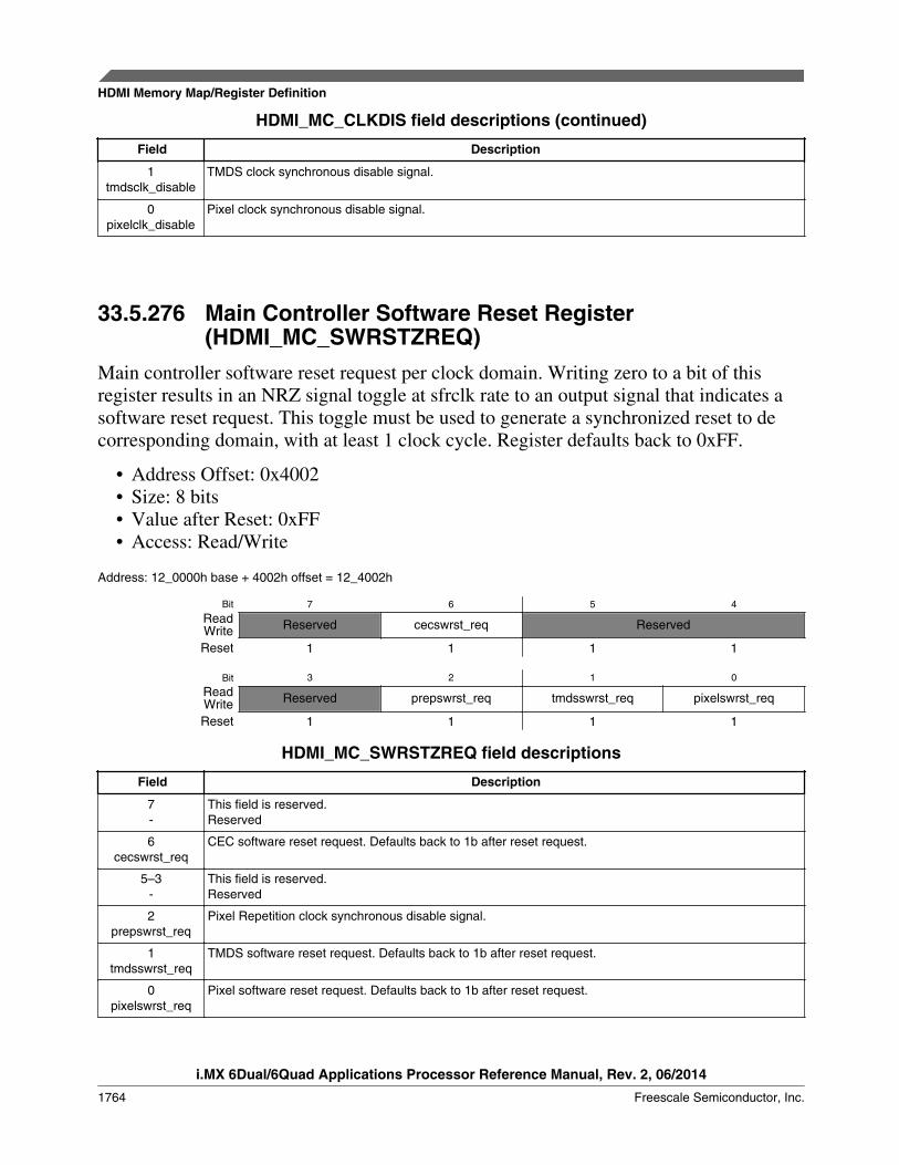
HDMI_MC_CLKDIS field descriptions (continued)
Field Description
1tmdsclk_disable
TMDS clock synchronous disable signal.
0pixelclk_disable
Pixel clock synchronous disable signal.
33.5.276 Main Controller Software Reset Register(HDMI_MC_SWRSTZREQ)
Main controller software reset request per clock domain. Writing zero to a bit of thisregister results in an NRZ signal toggle at sfrclk rate to an output signal that indicates asoftware reset request. This toggle must be used to generate a synchronized reset to decorresponding domain, with at least 1 clock cycle. Register defaults back to 0xFF.
• Address Offset: 0x4002• Size: 8 bits• Value after Reset: 0xFF• Access: Read/Write
Address: 12_0000h base + 4002h offset = 12_4002h
Bit 7 6 5 4
Read Reserved cecswrst_req ReservedWriteReset 1 1 1 1
Bit 3 2 1 0
Read Reserved prepswrst_req tmdsswrst_req pixelswrst_reqWriteReset 1 1 1 1
HDMI_MC_SWRSTZREQ field descriptions
Field Description
7-
This field is reserved.Reserved
6cecswrst_req
CEC software reset request. Defaults back to 1b after reset request.
5–3-
This field is reserved.Reserved
2prepswrst_req
Pixel Repetition clock synchronous disable signal.
1tmdsswrst_req
TMDS software reset request. Defaults back to 1b after reset request.
0pixelswrst_req
Pixel software reset request. Defaults back to 1b after reset request.
HDMI Memory Map/Register Definition
i.MX 6Dual/6Quad Applications Processor Reference Manual, Rev. 2, 06/2014
1764 Freescale Semiconductor, Inc.

33.5.277 Main Controller Feed Through Control Register(HDMI_MC_FLOWCTRL)
• Address Offset: 0x4004• Size: 8 bits• Value after Reset: 0x00• Access: Read/Write
Address: 12_0000h base + 4004h offset = 12_4004h
Bit 7 6 5 4 3 2 1 0
ReadReserved
Feed_through_offWrite
Reset 0 0 0 0 0 0 0 0
HDMI_MC_FLOWCTRL field descriptions
Field Description
7–1-
This field is reserved.Reserved
0Feed_through_off
Video path Feed Through enable bit:
1 Color Space Converter is in the video data path.0 Color Space Converter is bypassed (not in the video data path).
33.5.278 Main Controller PHY Reset Register(HDMI_MC_PHYRSTZ)
• Address Offset: 0x4005• Size: 8 bits• Value after Reset: 0x00• Access: Read/Write
Address: 12_0000h base + 4005h offset = 12_4005h
Bit 7 6 5 4 3 2 1 0
Read Reserved phyrstzWriteReset 0 0 0 0 0 0 0 0
Chapter 33 HDMI Transmitter (HDMI)
i.MX 6Dual/6Quad Applications Processor Reference Manual, Rev. 2, 06/2014
Freescale Semiconductor, Inc. 1765
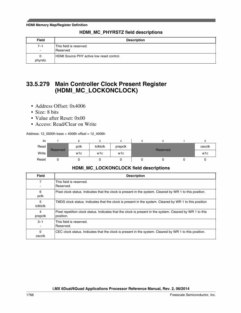
HDMI_MC_PHYRSTZ field descriptions
Field Description
7–1-
This field is reserved.Reserved
0phyrstz
HDMI Source PHY active low reset control.
33.5.279 Main Controller Clock Present Register(HDMI_MC_LOCKONCLOCK)
• Address Offset: 0x4006• Size: 8 bits• Value after Reset: 0x00• Access: Read/Clear on Write
Address: 12_0000h base + 4006h offset = 12_4006h
Bit 7 6 5 4 3 2 1 0
ReadReserved
pclk tclktclk prepclkReserved
cecclk
Write w1c w1c w1c w1c
Reset 0 0 0 0 0 0 0 0
HDMI_MC_LOCKONCLOCK field descriptions
Field Description
7-
This field is reserved.Reserved.
6pclk
Pixel clock status. Indicates that the clock is present in the system. Cleared by WR 1 to this position.
5tclktclk
TMDS clock status. Indicates that the clock is present in the system. Cleared by WR 1 to this position
4prepclk
Pixel repetition clock status. Indicates that the clock is present in the system. Cleared by WR 1 to thisposition.
3–1-
This field is reserved.Reserved.
0cecclk
CEC clock status. Indicates that the clock is present in the system. Cleared by WR 1 to this position.
HDMI Memory Map/Register Definition
i.MX 6Dual/6Quad Applications Processor Reference Manual, Rev. 2, 06/2014
1766 Freescale Semiconductor, Inc.
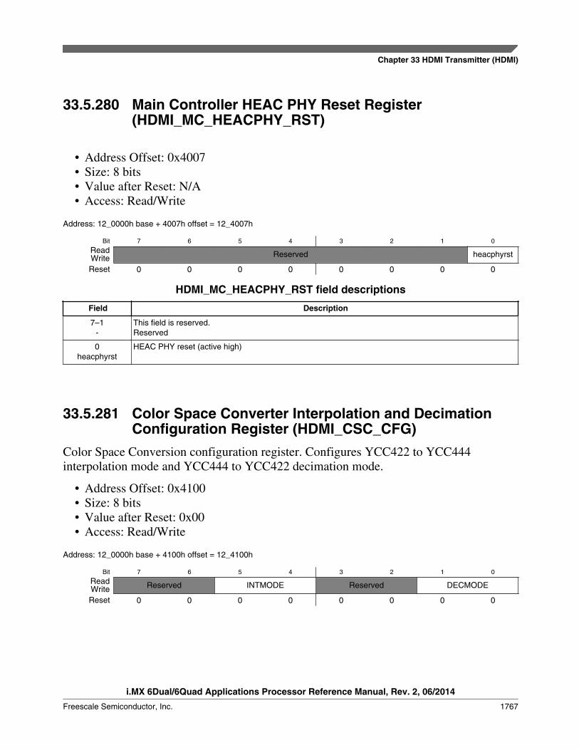
33.5.280 Main Controller HEAC PHY Reset Register(HDMI_MC_HEACPHY_RST)
• Address Offset: 0x4007• Size: 8 bits• Value after Reset: N/A• Access: Read/Write
Address: 12_0000h base + 4007h offset = 12_4007h
Bit 7 6 5 4 3 2 1 0
Read Reserved heacphyrstWriteReset 0 0 0 0 0 0 0 0
HDMI_MC_HEACPHY_RST field descriptions
Field Description
7–1-
This field is reserved.Reserved
0heacphyrst
HEAC PHY reset (active high)
33.5.281 Color Space Converter Interpolation and DecimationConfiguration Register (HDMI_CSC_CFG)
Color Space Conversion configuration register. Configures YCC422 to YCC444interpolation mode and YCC444 to YCC422 decimation mode.
• Address Offset: 0x4100• Size: 8 bits• Value after Reset: 0x00• Access: Read/Write
Address: 12_0000h base + 4100h offset = 12_4100h
Bit 7 6 5 4 3 2 1 0
Read Reserved INTMODE Reserved DECMODEWriteReset 0 0 0 0 0 0 0 0
Chapter 33 HDMI Transmitter (HDMI)
i.MX 6Dual/6Quad Applications Processor Reference Manual, Rev. 2, 06/2014
Freescale Semiconductor, Inc. 1767

HDMI_CSC_CFG field descriptions
Field Description
7–6-
This field is reserved.Reserved
5–4INTMODE
Chroma interpolation configuration:
00 interpolation disabled
01 H u (z) = 1 + z -1
10 H u (z)=1/2 + Z -1 +1/2 z -2
11 interpolation disabled.
3–2-
This field is reserved.Reserved
DECMODE Chroma decimation configuration: DECMODE[1:0] Chroma decimation 00 decimation disabled 01 H d? z?=1 10 H d? z?=1/ 4?1/ 2 z?1?1/4 z?2 11 H d? z?!211=?5?12 z?2?22 z?4?39 z?6?65 z?8?109 z?10?204z?12?648 z?14?1024 z?15?648 z?16?204 z?18?109 z?20?65 z?22?39 z?24?22 z?26?12 z?28?5 z?30
00 decimation disabled
01 H d (z) = 1
10 H d (Z)=1/4 + 1/2z -1 1+1/4z -2
11H d (z)x2 11 =-5+12z -2 +22z -4 +39z -8 +109z -10 -204z -12 +648z -14 +1024z -15 +648z -16 -204z -18
+109z -20 -65z -22 +39z -24 -22z -26 +12z -28 -5z -30
33.5.282 Color Space Converter Scale and Deep ColorConfiguration Register (HDMI_CSC_SCALE)
• Address Offset: 0x4101• Size: 8 bits• Value after Reset: 0x01• Access: Read/Write
GRB
= 2 csc scale - 12 x
A1 A2 A3
B1 B2 B3
C1 C2 C3
+ 2 csc scale x
A4
B4
C4
YCbCr
= 2 cscscale - 12 x
A1 A2 A3
B1 B2 B3
C1 C2 C3
+ 2 cscscale x
A4
B4
C4
Figure 33-299. CSC Conversion Functions
HDMI Memory Map/Register Definition
i.MX 6Dual/6Quad Applications Processor Reference Manual, Rev. 2, 06/2014
1768 Freescale Semiconductor, Inc.

Address: 12_0000h base + 4101h offset = 12_4101h
Bit 7 6 5 4 3 2 1 0
Read csc_colorde_pth[3:0] Reserved -WriteReset 0 0 0 0 0 0 0 1
HDMI_CSC_SCALE field descriptions
Field Description
7–4csc_colorde_
pth[3:0]
Color space converter color depth configuration:
Other: Reserved.
0000 24 bit per pixel video (8 bit per component).0100 24 bit per pixel video (8 bit per component).0101 30 bit per pixel video (10 bit per component).0110 36 bit per pixel video (12 bit per component).0111 48 bit per pixel video (16 bit per component).
3–2-
This field is reserved.Reserved
- Defines the cscscale[1:0] scale factor to apply to all coefficients in Color Space Conversion. This scalefactor is expressed in the number of left shifts to apply to each of the coefficients, ranging from 0 to 2.
33.5.283 CSC_COEF_A1_MSB (HDMI_CSC_COEF_A1_MSB)Color Space Conversion A1 coefficient.
• Address Offset: 0x4102• Size: 8 bits• Value after Reset: 0x20• Access: Read/Write
Address: 12_0000h base + 4102h offset = 12_4102h
Bit 7 6 5 4 3 2 1 0
Read CSC_COEF_A1_MSBWriteReset 0 0 1 0 0 0 0 0
HDMI_CSC_COEF_A1_MSB field descriptions
Field Description
CSC_COEF_A1_MSB
Color Space Conversion A1 MSB coefficient.
33.5.284 CSC_COEF_A1_LSB (HDMI_CSC_COEF_A1_LSB)Color Space Conversion A1 coefficient.
Chapter 33 HDMI Transmitter (HDMI)
i.MX 6Dual/6Quad Applications Processor Reference Manual, Rev. 2, 06/2014
Freescale Semiconductor, Inc. 1769

• Address Offset: 0x4103• Size: 8 bits• Value after Reset: 0x00• Access: Read/Write
Address: 12_0000h base + 4103h offset = 12_4103h
Bit 7 6 5 4 3 2 1 0
Read CSC_COEF_A1_LSBWriteReset 0 0 0 0 0 0 0 0
HDMI_CSC_COEF_A1_LSB field descriptions
Field Description
CSC_COEF_A1_LSB
Color Space Conversion A1 LSB coefficient
33.5.285 CSC_COEF_A2_MSB (HDMI_CSC_COEF_A2_MSB)Color Space Conversion A2 coefficient.
• Address Offset: 0x4104• Size: 8 bits• Value after Reset: 0x00• Access: Read/Write
Address: 12_0000h base + 4104h offset = 12_4104h
Bit 7 6 5 4 3 2 1 0
Read CSC_COEF_A2_MSBWriteReset 0 0 0 0 0 0 0 0
HDMI_CSC_COEF_A2_MSB field descriptions
Field Description
CSC_COEF_A2_MSB
Color Space Conversion A2 MSB coefficient.
33.5.286 CSC_COEF_A2_LSB (HDMI_CSC_COEF_A2_LSB)Color Space Conversion A2 coefficient.
• Address Offset: 0x4105• Size: 8 bits
HDMI Memory Map/Register Definition
i.MX 6Dual/6Quad Applications Processor Reference Manual, Rev. 2, 06/2014
1770 Freescale Semiconductor, Inc.

• Value after Reset: 0x00• Access: Read/Write
Address: 12_0000h base + 4105h offset = 12_4105h
Bit 7 6 5 4 3 2 1 0
Read CSC_COEF_A2_LSBWriteReset 0 0 0 0 0 0 0 0
HDMI_CSC_COEF_A2_LSB field descriptions
Field Description
CSC_COEF_A2_LSB
Color Space Conversion A2 LSB coefficient.
33.5.287 CSC_COEF_A3_MSB (HDMI_CSC_COEF_A3_MSB)Color Space Conversion A3 coefficient.
• Address Offset: 0x4106• Size: 8 bits• Value after Reset: 0x00• Access: Read/Write
Address: 12_0000h base + 4106h offset = 12_4106h
Bit 7 6 5 4 3 2 1 0
Read CSC_COEF_A3_MSBWriteReset 0 0 0 0 0 0 0 0
HDMI_CSC_COEF_A3_MSB field descriptions
Field Description
CSC_COEF_A3_MSB
Color Space Conversion A3 MSB coefficient.
33.5.288 CSC_COEF_A3_LSB (HDMI_CSC_COEF_A3_LSB)Color Space Conversion A3 coefficient.
• Address Offset: 0x4107• Size: 8 bits• Value after Reset: 0x00• Access: Read/Write
Chapter 33 HDMI Transmitter (HDMI)
i.MX 6Dual/6Quad Applications Processor Reference Manual, Rev. 2, 06/2014
Freescale Semiconductor, Inc. 1771
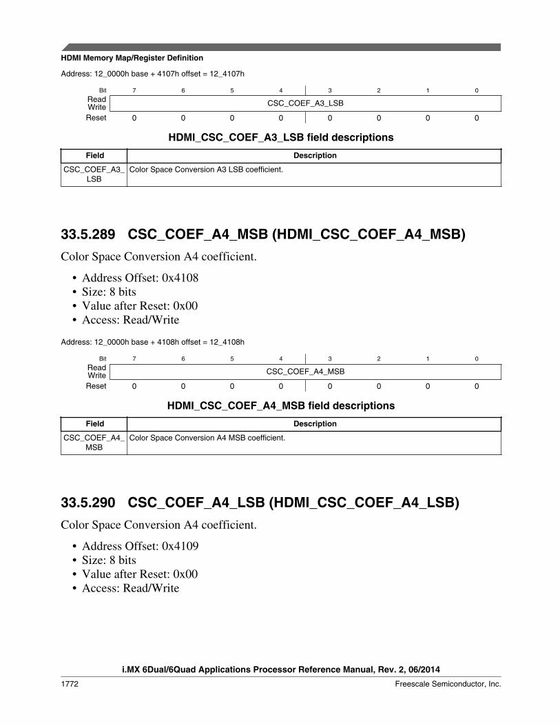
Address: 12_0000h base + 4107h offset = 12_4107h
Bit 7 6 5 4 3 2 1 0
Read CSC_COEF_A3_LSBWriteReset 0 0 0 0 0 0 0 0
HDMI_CSC_COEF_A3_LSB field descriptions
Field Description
CSC_COEF_A3_LSB
Color Space Conversion A3 LSB coefficient.
33.5.289 CSC_COEF_A4_MSB (HDMI_CSC_COEF_A4_MSB)Color Space Conversion A4 coefficient.
• Address Offset: 0x4108• Size: 8 bits• Value after Reset: 0x00• Access: Read/Write
Address: 12_0000h base + 4108h offset = 12_4108h
Bit 7 6 5 4 3 2 1 0
Read CSC_COEF_A4_MSBWriteReset 0 0 0 0 0 0 0 0
HDMI_CSC_COEF_A4_MSB field descriptions
Field Description
CSC_COEF_A4_MSB
Color Space Conversion A4 MSB coefficient.
33.5.290 CSC_COEF_A4_LSB (HDMI_CSC_COEF_A4_LSB)Color Space Conversion A4 coefficient.
• Address Offset: 0x4109• Size: 8 bits• Value after Reset: 0x00• Access: Read/Write
HDMI Memory Map/Register Definition
i.MX 6Dual/6Quad Applications Processor Reference Manual, Rev. 2, 06/2014
1772 Freescale Semiconductor, Inc.

Address: 12_0000h base + 4109h offset = 12_4109h
Bit 7 6 5 4 3 2 1 0
Read CSC_COEF_A4_LSBWriteReset 0 0 0 0 0 0 0 0
HDMI_CSC_COEF_A4_LSB field descriptions
Field Description
CSC_COEF_A4_LSB
Color Space Conversion A4 LSB coefficient.
33.5.291 CSC_COEF_B1_MSB (HDMI_CSC_COEF_B1_MSB)Color Space Conversion B1 coefficient.
• Address Offset: 0x410A• Size: 8 bits• Value after Reset: 0x00• Access: Read/Write
Address: 12_0000h base + 410Ah offset = 12_410Ah
Bit 7 6 5 4 3 2 1 0
Read CSC_COEF_B1_MSBWriteReset 0 0 0 0 0 0 0 0
HDMI_CSC_COEF_B1_MSB field descriptions
Field Description
CSC_COEF_B1_MSB
Color Space Conversion B1 MSB coefficient.
33.5.292 CSC_COEF_B1_LSB (HDMI_CSC_COEF_B1_LSB)Color Space Conversion B1 coefficient.
• Address Offset: 0x410B• Size: 8 bits• Value after Reset: 0x00• Access: Read/Write
Chapter 33 HDMI Transmitter (HDMI)
i.MX 6Dual/6Quad Applications Processor Reference Manual, Rev. 2, 06/2014
Freescale Semiconductor, Inc. 1773

Address: 12_0000h base + 410Bh offset = 12_410Bh
Bit 7 6 5 4 3 2 1 0
Read CSC_COEF_B1_LSBWriteReset 0 0 0 0 0 0 0 0
HDMI_CSC_COEF_B1_LSB field descriptions
Field Description
CSC_COEF_B1_LSB
Color Space Conversion B1 LSB coefficient.
33.5.293 CSC_COEF_B2_MSB (HDMI_CSC_COEF_B2_MSB)Color Space Conversion B2 coefficient.
• Address Offset: 0x410C• Size: 8 bits• Value after Reset: 0x20• Access: Read/Write
Address: 12_0000h base + 410Ch offset = 12_410Ch
Bit 7 6 5 4 3 2 1 0
Read CSC_COEF_B2_MSBWriteReset 0 0 1 0 0 0 0 0
HDMI_CSC_COEF_B2_MSB field descriptions
Field Description
CSC_COEF_B2_MSB
Color Space Conversion B2 MSB coefficient.
33.5.294 CSC_COEF_B2_LSB (HDMI_CSC_COEF_B2_LSB)Color Space Conversion B2 coefficient.
• Address Offset: 0x410D• Size: 8 bits• Value after Reset: 0x00• Access: Read/Write
HDMI Memory Map/Register Definition
i.MX 6Dual/6Quad Applications Processor Reference Manual, Rev. 2, 06/2014
1774 Freescale Semiconductor, Inc.

Address: 12_0000h base + 410Dh offset = 12_410Dh
Bit 7 6 5 4 3 2 1 0
Read CSC_COEF_B2_LSBWriteReset 0 0 0 0 0 0 0 0
HDMI_CSC_COEF_B2_LSB field descriptions
Field Description
CSC_COEF_B2_LSB
Color Space Conversion B2 LSB coefficient.
33.5.295 CSC_COEF_B3_MSB (HDMI_CSC_COEF_B3_MSB)Color Space Conversion B3 coefficient.
• Address Offset: 0x410E• Size: 8 bits• Value after Reset: 0x00• Access: Read/Write
Address: 12_0000h base + 410Eh offset = 12_410Eh
Bit 7 6 5 4 3 2 1 0
Read CSC_COEF_B3_MSBWriteReset 0 0 0 0 0 0 0 0
HDMI_CSC_COEF_B3_MSB field descriptions
Field Description
CSC_COEF_B3_MSB
Color Space Conversion B3 MSB coefficient.
33.5.296 CSC_COEF_B3_LSB (HDMI_CSC_COEF_B3_LSB)Color Space Conversion B3 coefficient.
• Address Offset: 0x410F• Size: 8 bits• Value after Reset: 0x00• Access: Read/Write
Chapter 33 HDMI Transmitter (HDMI)
i.MX 6Dual/6Quad Applications Processor Reference Manual, Rev. 2, 06/2014
Freescale Semiconductor, Inc. 1775

Address: 12_0000h base + 410Fh offset = 12_410Fh
Bit 7 6 5 4 3 2 1 0
Read CSC_COEF_B3_LSBWriteReset 0 0 0 0 0 0 0 0
HDMI_CSC_COEF_B3_LSB field descriptions
Field Description
CSC_COEF_B3_LSB
Color Space Conversion B3 LSB coefficient.
33.5.297 CSC_COEF_B4_MSB (HDMI_CSC_COEF_B4_MSB)Color Space Conversion B4 coefficient.
• Address Offset: 0x4110• Size: 8 bits• Value after Reset: 0x00• Access: Read/Write
Address: 12_0000h base + 4110h offset = 12_4110h
Bit 7 6 5 4 3 2 1 0
Read CSC_COEF_B4_MSBWriteReset 0 0 0 0 0 0 0 0
HDMI_CSC_COEF_B4_MSB field descriptions
Field Description
CSC_COEF_B4_MSB
Color Space Conversion B4 MSB coefficient.
33.5.298 CSC_COEF_B4_LSB (HDMI_CSC_COEF_B4_LSB)Color Space Conversion B4 coefficient.
• Address Offset: 0x4111• Size: 8 bits• Value after Reset: 0x00• Access: Read/Write
HDMI Memory Map/Register Definition
i.MX 6Dual/6Quad Applications Processor Reference Manual, Rev. 2, 06/2014
1776 Freescale Semiconductor, Inc.
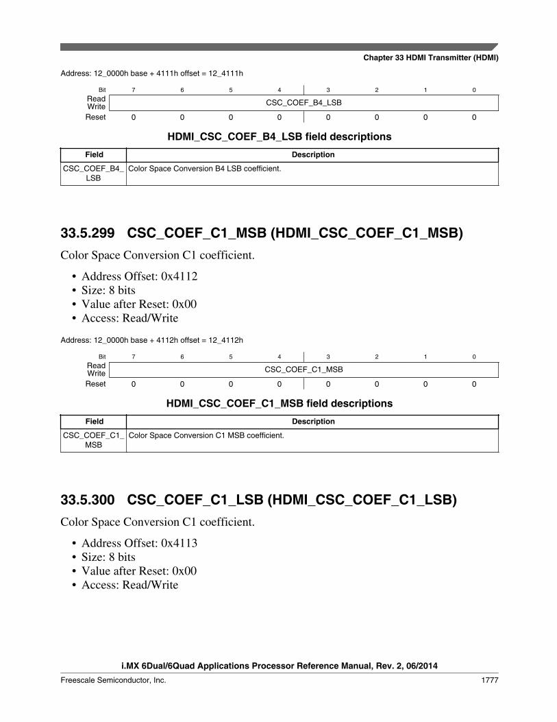
Address: 12_0000h base + 4111h offset = 12_4111h
Bit 7 6 5 4 3 2 1 0
Read CSC_COEF_B4_LSBWriteReset 0 0 0 0 0 0 0 0
HDMI_CSC_COEF_B4_LSB field descriptions
Field Description
CSC_COEF_B4_LSB
Color Space Conversion B4 LSB coefficient.
33.5.299 CSC_COEF_C1_MSB (HDMI_CSC_COEF_C1_MSB)Color Space Conversion C1 coefficient.
• Address Offset: 0x4112• Size: 8 bits• Value after Reset: 0x00• Access: Read/Write
Address: 12_0000h base + 4112h offset = 12_4112h
Bit 7 6 5 4 3 2 1 0
Read CSC_COEF_C1_MSBWriteReset 0 0 0 0 0 0 0 0
HDMI_CSC_COEF_C1_MSB field descriptions
Field Description
CSC_COEF_C1_MSB
Color Space Conversion C1 MSB coefficient.
33.5.300 CSC_COEF_C1_LSB (HDMI_CSC_COEF_C1_LSB)Color Space Conversion C1 coefficient.
• Address Offset: 0x4113• Size: 8 bits• Value after Reset: 0x00• Access: Read/Write
Chapter 33 HDMI Transmitter (HDMI)
i.MX 6Dual/6Quad Applications Processor Reference Manual, Rev. 2, 06/2014
Freescale Semiconductor, Inc. 1777

Address: 12_0000h base + 4113h offset = 12_4113h
Bit 7 6 5 4 3 2 1 0
Read CSC_COEF_C1_LSBWriteReset 0 0 0 0 0 0 0 0
HDMI_CSC_COEF_C1_LSB field descriptions
Field Description
CSC_COEF_C1_LSB
Color Space Conversion C1 LSB coefficient.
33.5.301 CSC_COEF_C2_MSB (HDMI_CSC_COEF_C2_MSB)Color Space Conversion C2 coefficient.
• Address Offset: 0x4114• Size: 8 bits• Value after Reset: 0x00• Access: Read/Write
Address: 12_0000h base + 4114h offset = 12_4114h
Bit 7 6 5 4 3 2 1 0
Read CSC_COEF_C2_MSBWriteReset 0 0 0 0 0 0 0 0
HDMI_CSC_COEF_C2_MSB field descriptions
Field Description
CSC_COEF_C2_MSB
Color Space Conversion C2 MSB coefficient.
33.5.302 CSC_COEF_C2_LSB (HDMI_CSC_COEF_C2_LSB)Color Space Conversion C2 coefficient.
• Address Offset: 0x4115• Size: 8 bits• Value after Reset: 0x00• Access: Read/Write
HDMI Memory Map/Register Definition
i.MX 6Dual/6Quad Applications Processor Reference Manual, Rev. 2, 06/2014
1778 Freescale Semiconductor, Inc.

Address: 12_0000h base + 4115h offset = 12_4115h
Bit 7 6 5 4 3 2 1 0
Read CSC_COEF_C2_LSBWriteReset 0 0 0 0 0 0 0 0
HDMI_CSC_COEF_C2_LSB field descriptions
Field Description
CSC_COEF_C2_LSB
Color Space Conversion C2 LSB coefficient.
33.5.303 CSC_COEF_C3_MSB (HDMI_CSC_COEF_C3_MSB)Color Space Conversion C3 coefficient.
• Address Offset: 0x4116• Size: 8 bits• Value after Reset: 0x20• Access: Read/Write
Address: 12_0000h base + 4116h offset = 12_4116h
Bit 7 6 5 4 3 2 1 0
Read CSC_COEF_C3_MSBWriteReset 0 0 1 0 0 0 0 0
HDMI_CSC_COEF_C3_MSB field descriptions
Field Description
CSC_COEF_C3_MSB
Color Space Conversion C3 MSB coefficient.
33.5.304 CSC_COEF_C3_LSB (HDMI_CSC_COEF_C3_LSB)Color Space Conversion C3 coefficient.
• Address Offset: 0x4117• Size: 8 bits• Value after Reset: 0x00• Access: Read/Write
Chapter 33 HDMI Transmitter (HDMI)
i.MX 6Dual/6Quad Applications Processor Reference Manual, Rev. 2, 06/2014
Freescale Semiconductor, Inc. 1779
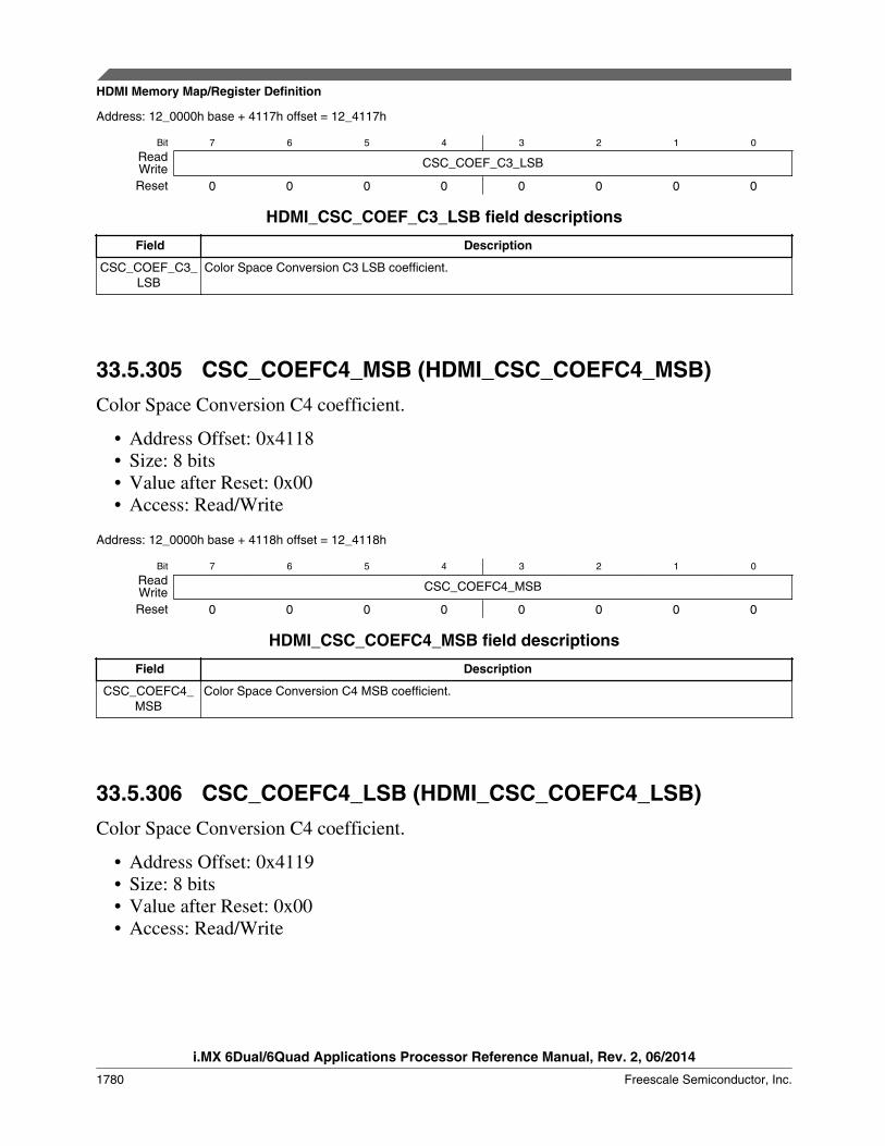
Address: 12_0000h base + 4117h offset = 12_4117h
Bit 7 6 5 4 3 2 1 0
Read CSC_COEF_C3_LSBWriteReset 0 0 0 0 0 0 0 0
HDMI_CSC_COEF_C3_LSB field descriptions
Field Description
CSC_COEF_C3_LSB
Color Space Conversion C3 LSB coefficient.
33.5.305 CSC_COEFC4_MSB (HDMI_CSC_COEFC4_MSB)Color Space Conversion C4 coefficient.
• Address Offset: 0x4118• Size: 8 bits• Value after Reset: 0x00• Access: Read/Write
Address: 12_0000h base + 4118h offset = 12_4118h
Bit 7 6 5 4 3 2 1 0
Read CSC_COEFC4_MSBWriteReset 0 0 0 0 0 0 0 0
HDMI_CSC_COEFC4_MSB field descriptions
Field Description
CSC_COEFC4_MSB
Color Space Conversion C4 MSB coefficient.
33.5.306 CSC_COEFC4_LSB (HDMI_CSC_COEFC4_LSB)Color Space Conversion C4 coefficient.
• Address Offset: 0x4119• Size: 8 bits• Value after Reset: 0x00• Access: Read/Write
HDMI Memory Map/Register Definition
i.MX 6Dual/6Quad Applications Processor Reference Manual, Rev. 2, 06/2014
1780 Freescale Semiconductor, Inc.
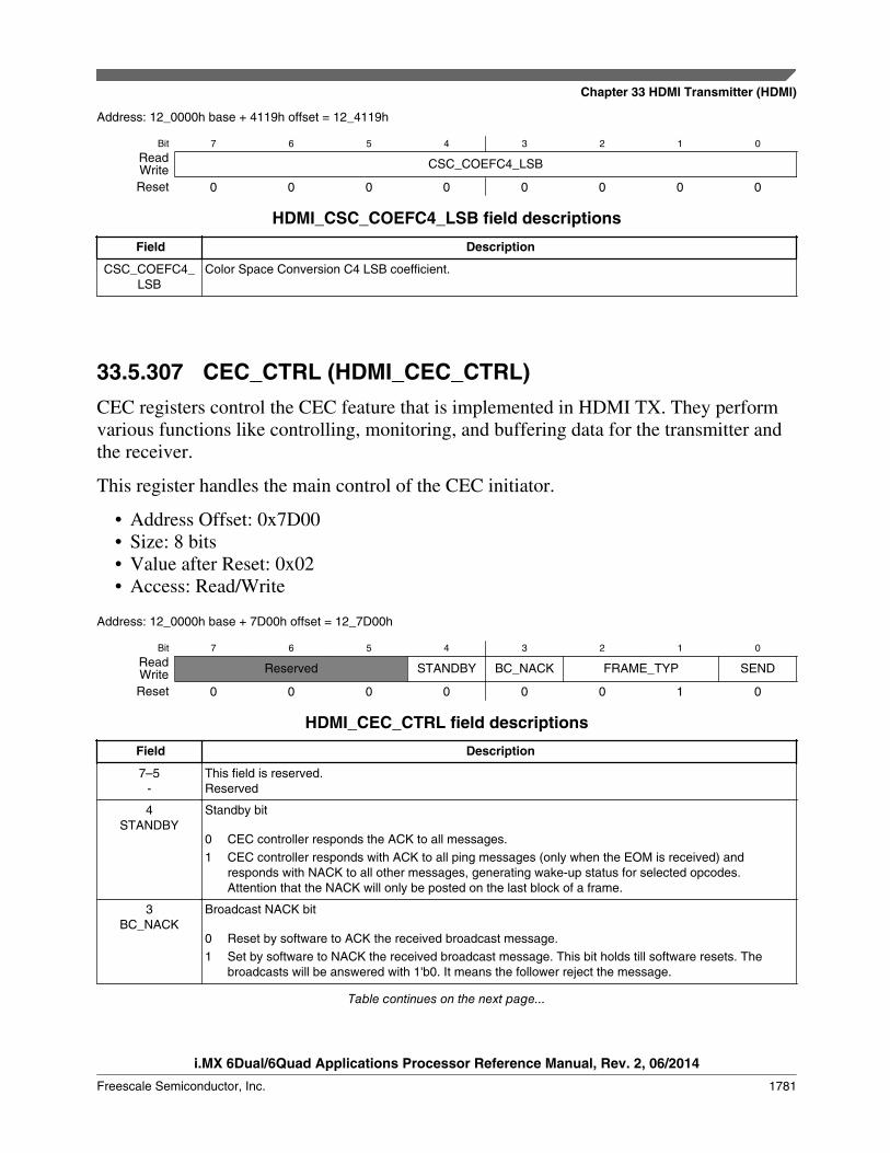
Address: 12_0000h base + 4119h offset = 12_4119h
Bit 7 6 5 4 3 2 1 0
Read CSC_COEFC4_LSBWriteReset 0 0 0 0 0 0 0 0
HDMI_CSC_COEFC4_LSB field descriptions
Field Description
CSC_COEFC4_LSB
Color Space Conversion C4 LSB coefficient.
33.5.307 CEC_CTRL (HDMI_CEC_CTRL)CEC registers control the CEC feature that is implemented in HDMI TX. They performvarious functions like controlling, monitoring, and buffering data for the transmitter andthe receiver.
This register handles the main control of the CEC initiator.
• Address Offset: 0x7D00• Size: 8 bits• Value after Reset: 0x02• Access: Read/Write
Address: 12_0000h base + 7D00h offset = 12_7D00h
Bit 7 6 5 4 3 2 1 0
Read Reserved STANDBY BC_NACK FRAME_TYP SENDWriteReset 0 0 0 0 0 0 1 0
HDMI_CEC_CTRL field descriptions
Field Description
7–5-
This field is reserved.Reserved
4STANDBY
Standby bit
0 CEC controller responds the ACK to all messages.1 CEC controller responds with ACK to all ping messages (only when the EOM is received) and
responds with NACK to all other messages, generating wake-up status for selected opcodes.Attention that the NACK will only be posted on the last block of a frame.
3BC_NACK
Broadcast NACK bit
0 Reset by software to ACK the received broadcast message.1 Set by software to NACK the received broadcast message. This bit holds till software resets. The
broadcasts will be answered with 1'b0. It means the follower reject the message.
Table continues on the next page...
Chapter 33 HDMI Transmitter (HDMI)
i.MX 6Dual/6Quad Applications Processor Reference Manual, Rev. 2, 06/2014
Freescale Semiconductor, Inc. 1781

HDMI_CEC_CTRL field descriptions (continued)
Field Description
2–1FRAME_TYP
Frame Type bit
00 Signal Free Time = 3-bit periods. Previous attempt to send frame is unsuccessful.01 Signal Free Time = 5-bit periods. New initiator wants to send a frame.10 Signal Free Time = 7-bit periods. Present initiator wants to send another frame immediately after its
previous frame. (spec CEC 9.1)11 Illegal value. If software write this value, hardware will set the value to the default 2'b01.
0SEND
Send bit
0 Reset to 0 by hardware when the CEC transmission is done (no matter successful or failed). It canalso work as an indicator checked by software to see whether the transmission is finished.
1 Set by software to trigger CEC sending a frame as an initiator. This bit keeps at 1 while thetransmission is going on.
33.5.308 CEC_STAT (HDMI_CEC_STAT)This register indicates the status of CEC line. All bits are read only. When an eventoccurs, the corresponding bit will set to 1 for one SFR clock cycle only. Then, the bitautomatically resets to 0. No software reset is required. Software can read the "stable"interrupts on IH_CEC_STAT0 register (this register has the same bit arrangement asCEC_STAT register).
• Address Offset: 0x7D01• Size: 8 bits• Value after Reset: N/A• Access: Read
Address: 12_0000h base + 7D01h offset = 12_7D01h
Bit 7 6 5 4 3 2 1 0
ReadReserved
WAKEUPERROR_
FOLLERROR_
INITARB_LOST NACK EOM DONE
Write
Reset 0 0 0 0 0 0 0 0
HDMI_CEC_STAT field descriptions
Field Description
7-
This field is reserved.Reserved
6WAKEUP
Follower received wake-up command (for follower only).
5ERROR_FOLL
An error is notified by a follower. Abnormal logic data bit error (for follower).
Table continues on the next page...
HDMI Memory Map/Register Definition
i.MX 6Dual/6Quad Applications Processor Reference Manual, Rev. 2, 06/2014
1782 Freescale Semiconductor, Inc.

HDMI_CEC_STAT field descriptions (continued)
Field Description
4ERROR_INIT
An error is detected on cec line (for initiator only).
3ARB_LOST
The initiator losses the CEC line arbitration to a second initiator. (specification CEC 9).
2NACK
A frame is not acknowledged in a directly addressed message. Or a frame is negatively acknowledged ina broadcast message (for initiator only).
1EOM
EOM is detected so that the received data is ready in the receiver data buffer (for follower only).
0DONE
The current transmission is successful (for initiator only).
33.5.309 CEC_MASK (HDMI_CEC_MASK)This read/write register masks/unmasks the interrupt events. When the bit is set to 1(masked), the corresponding event will not trigger an interrupt signal at the systeminterface. When the bit is reset to 0, the interrupt event is unmasked.
• Address Offset: 0x7D02• Size: 8 bits• Value after Reset: 0x00• Access: Read/Write
Address: 12_0000h base + 7D02h offset = 12_7D02h
Bit 7 6 5 4 3 2 1 0
Read
ReservedWAKEUP_
MASK
ERROR_FOLL_MASK
ERROR_INIT_MASK
ARB_LOST_MASK
NACK_MASK
EOM_MASKDONE_MASKWrite
Reset 0 0 0 0 0 0 0 0
HDMI_CEC_MASK field descriptions
Field Description
7-
This field is reserved.Reserved
6WAKEUP_MASK
Follower wake-up signal mask
5ERROR_FOLL_
MASK
An error is notified by a follower. Abnormal logic data bit error (for follower).
4ERROR_INIT_
MASK
An error is detected on cec line (for initiator only).
Table continues on the next page...
Chapter 33 HDMI Transmitter (HDMI)
i.MX 6Dual/6Quad Applications Processor Reference Manual, Rev. 2, 06/2014
Freescale Semiconductor, Inc. 1783

HDMI_CEC_MASK field descriptions (continued)
Field Description
3ARB_LOST_
MASK
The initiator losses the CEC line arbitration to a second initiator. (specification CEC 9).
2NACK_MASK
A frame is not acknowledged in a directly addressed message. Or a frame is negatively acknowledged ina broadcast message (for initiator only).
1EOM_MASK
EOM is detected so that the received data is ready in the receiver data buffer (for follower only).
0DONE_MASK
The current transmission is successful (for initiator only).
33.5.310 CEC_POLARITY (HDMI_CEC_POLARITY)This register is readable and writable, which controls the polarity of the interrupt statusregister as well as the polarity of the interrupt signals at system interface.
• Address Offset: 0x7D03• Size: 8 bits• Value after Reset: 0x7F• Access: Read/Write
Address: 12_0000h base + 7D03h offset = 12_7D03h
Bit 7 6 5 4 3 2 1 0
ReadReserved
WAKEUP_POL
ERROR_FOLL_POL
ERROR_INIT_POL
ARB_LOST_POL
NACK_POL EOM_POL DONE_POLWrite
Reset 0 1 1 1 1 1 1 1
HDMI_CEC_POLARITY field descriptions
Field Description
7-
This field is reserved.Reserved
6WAKEUP_POL
Follower wakeup signal polarity
5ERROR_FOLL_
POL
CEC line error polarity (for follower only)
4ERROR_INIT_
POL
CEC line error polarity (for initiator only)
3ARB_LOST_POL
Initiator Arbitration lost signal polarity
2NACK_POL
Frame NACK signal polarity
Table continues on the next page...
HDMI Memory Map/Register Definition
i.MX 6Dual/6Quad Applications Processor Reference Manual, Rev. 2, 06/2014
1784 Freescale Semiconductor, Inc.
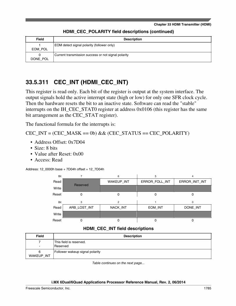
HDMI_CEC_POLARITY field descriptions (continued)
Field Description
1EOM_POL
EOM detect signal polarity (follower only)
0DONE_POL
Current transmission success or not signal polarity
33.5.311 CEC_INT (HDMI_CEC_INT)This register is read only. Each bit of the register is output at the system interface. Theoutput signals hold the active interrupt state (high or low) for only one SFR clock cycle.Then the hardware resets the bit to an inactive state. Software can read the "stable"interrupts on the IH_CEC_STAT0 register at address 0x0106 (this register has the samebit arrangement as the CEC_STAT register).
The functional formula for the interrupts is:
CEC_INT = (CEC_MASK == 0b) && (CEC_STATUS == CEC_POLARITY)
• Address Offset: 0x7D04• Size: 8 bits• Value after Reset: 0x00• Access: Read
Address: 12_0000h base + 7D04h offset = 12_7D04h
Bit 7 6 5 4
ReadReserved
WAKEUP_INT ERROR_FOLL_INT ERROR_INIT_INT
Write
Reset 0 0 0 0
Bit 3 2 1 0
Read ARB_LOST_INT NACK_INT EOM_INT DONE_INT
Write
Reset 0 0 0 0
HDMI_CEC_INT field descriptions
Field Description
7-
This field is reserved.Reserved
6WAKEUP_INT
Follower wakeup signal polarity
Table continues on the next page...
Chapter 33 HDMI Transmitter (HDMI)
i.MX 6Dual/6Quad Applications Processor Reference Manual, Rev. 2, 06/2014
Freescale Semiconductor, Inc. 1785

HDMI_CEC_INT field descriptions (continued)
Field Description
5ERROR_FOLL_
INT
Follower wakeup interrupt
4ERROR_INIT_
INT
CEC line error interrupt (for follower only)
3ARB_LOST_INT
CEC line error interrupt (for initiator only)
2NACK_INT
Initiator Arbitration lost interrupt
1EOM_INT
Frame NACK interrupt
0DONE_INT
EOM detect interrupt (for follower only)
33.5.312 CEC_ADDR_L (HDMI_CEC_ADDR_L)CEC_ADDR_L and CEC_ADDR_H registers indicate the logical address(es) allocated tothe CEC device. The logical address mappings are shown in CEC_ADDR_L(HDMI_CEC_ADDR_L) and CEC_ADDR_H (HDMI_CEC_ADDR_H) . This register iswritten by software when the logical allocation is finished. Bit value 1 means thecorresponding logical address is allocated to this device. Bit value 0 means thecorresponding logical address is not allocated to this device.
• Address Offset: 0x7D05• Size: 8 bits• Value after Reset: 0x00• Access: Read/Write
Address: 12_0000h base + 7D05h offset = 12_7D05h
Bit 7 6 5 4
Read CEC_ADDR_L7 CEC_ADDR_L6 CEC_ADDR_L5 CEC_ADDR_L4WriteReset 0 0 0 0
Bit 3 2 1 0
Read CEC_ADDR_L3 CEC_ADDR_L2 CEC_ADDR_L1 CEC_ADDR_L0WriteReset 0 0 0 0
HDMI Memory Map/Register Definition
i.MX 6Dual/6Quad Applications Processor Reference Manual, Rev. 2, 06/2014
1786 Freescale Semiconductor, Inc.
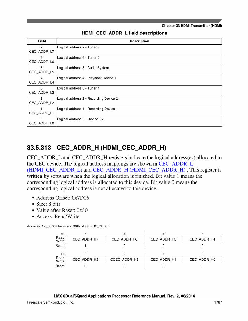
HDMI_CEC_ADDR_L field descriptions
Field Description
7CEC_ADDR_L7
Logical address 7 - Tuner 3
6CEC_ADDR_L6
Logical address 6 - Tuner 2
5CEC_ADDR_L5
Logical address 5 - Audio System
4CEC_ADDR_L4
Logical address 4 - Playback Device 1
3CEC_ADDR_L3
Logical address 3 - Tuner 1
2CEC_ADDR_L2
Logical address 2 - Recording Device 2
1CEC_ADDR_L1
Logical address 1 - Recording Device 1
0CEC_ADDR_L0
Logical address 0 - Device TV
33.5.313 CEC_ADDR_H (HDMI_CEC_ADDR_H)CEC_ADDR_L and CEC_ADDR_H registers indicate the logical address(es) allocated tothe CEC device. The logical address mappings are shown in CEC_ADDR_L(HDMI_CEC_ADDR_L) and CEC_ADDR_H (HDMI_CEC_ADDR_H) . This register iswritten by software when the logical allocation is finished. Bit value 1 means thecorresponding logical address is allocated to this device. Bit value 0 means thecorresponding logical address is not allocated to this device.
• Address Offset: 0x7D06• Size: 8 bits• Value after Reset: 0x80• Access: Read/Write
Address: 12_0000h base + 7D06h offset = 12_7D06h
Bit 7 6 5 4
Read CEC_ADDR_H7 CEC_ADDR_H6 CEC_ADDR_H5 CEC_ADDR_H4WriteReset 1 0 0 0
Bit 3 2 1 0
Read CEC_ADDR_H3 CCEC_ADDR_H2 CEC_ADDR_H1 CEC_ADDR_H0WriteReset 0 0 0 0
Chapter 33 HDMI Transmitter (HDMI)
i.MX 6Dual/6Quad Applications Processor Reference Manual, Rev. 2, 06/2014
Freescale Semiconductor, Inc. 1787

HDMI_CEC_ADDR_H field descriptions
Field Description
7CEC_ADDR_H7
Logical address 15 - Unregistered (as initiator address), Broadcast (as destination address)
6CEC_ADDR_H6
Logical address 14 - Free use
5CEC_ADDR_H5
Logical address 13 - Reserved
4CEC_ADDR_H4
Logical address 12 - Reserved
3CEC_ADDR_H3
Logical address 11 - Playback Device 3
2CCEC_ADDR_
H2
Logical address 10 - Tuner 4
1CEC_ADDR_H1
Logical address 9 - Playback Device 3
0CEC_ADDR_H0
Logical address 8 - Playback Device 2
33.5.314 CEC_TX_CNT (HDMI_CEC_TX_CNT)This register indicates the size of the frame in bytes (including header and data blocks),which are available in the transmitter data buffer.
When the value is zero, the CEC controller ignores the send command triggered bysoftware. When the transmission is done (no matter success or not), the current value isheld until it is overwritten by software.
• Address Offset: 0x7D07• Size: 8 bits• Value after Reset: 0x00• Access: Read/Write
Address: 12_0000h base + 7D07h offset = 12_7D07h
Bit 7 6 5 4 3 2 1 0
Read Reserved CEC_TX_CNTWriteReset 0 0 0 0 0 0 0 0
HDMI_CEC_TX_CNT field descriptions
Field Description
7–5-
This field is reserved.Reserved
Table continues on the next page...
HDMI Memory Map/Register Definition
i.MX 6Dual/6Quad Applications Processor Reference Manual, Rev. 2, 06/2014
1788 Freescale Semiconductor, Inc.
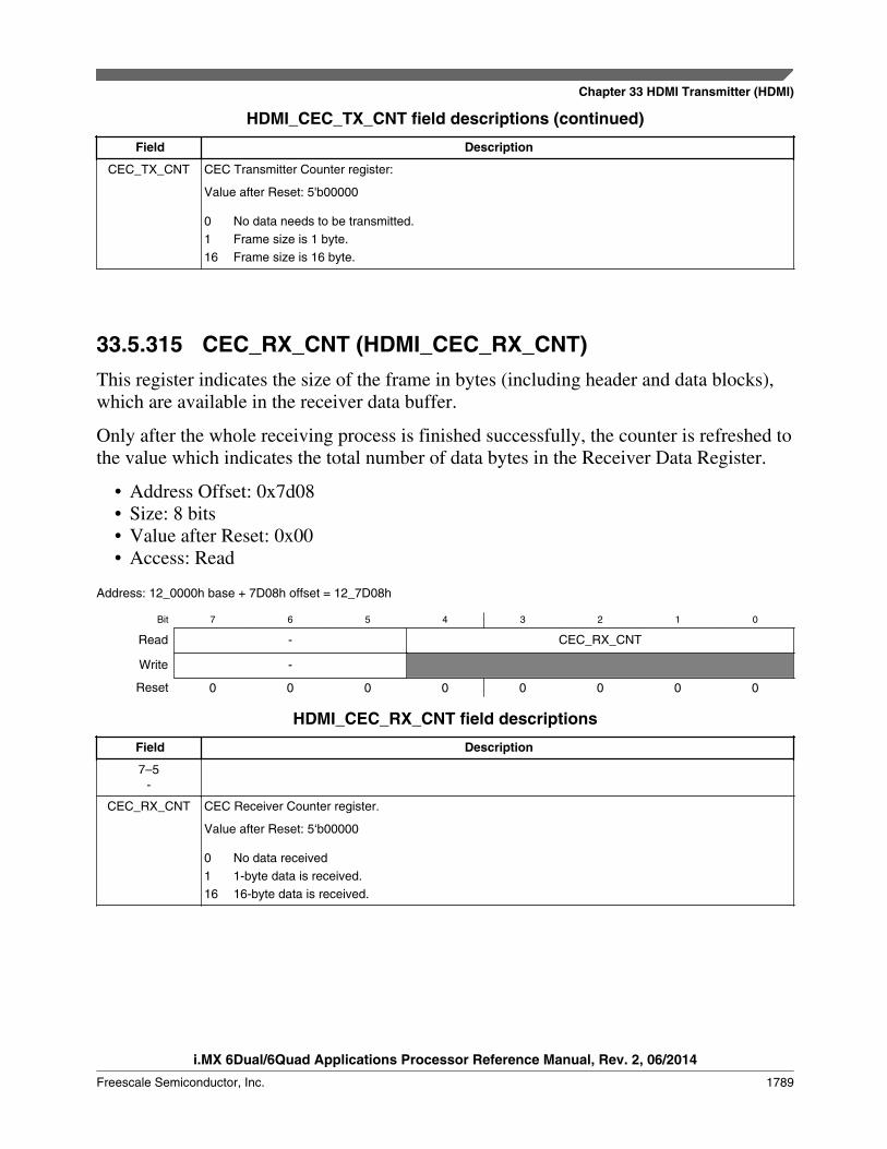
HDMI_CEC_TX_CNT field descriptions (continued)
Field Description
CEC_TX_CNT CEC Transmitter Counter register:
Value after Reset: 5'b00000
0 No data needs to be transmitted.1 Frame size is 1 byte.16 Frame size is 16 byte.
33.5.315 CEC_RX_CNT (HDMI_CEC_RX_CNT)This register indicates the size of the frame in bytes (including header and data blocks),which are available in the receiver data buffer.
Only after the whole receiving process is finished successfully, the counter is refreshed tothe value which indicates the total number of data bytes in the Receiver Data Register.
• Address Offset: 0x7d08• Size: 8 bits• Value after Reset: 0x00• Access: Read
Address: 12_0000h base + 7D08h offset = 12_7D08h
Bit 7 6 5 4 3 2 1 0
Read - CEC_RX_CNT
Write -
Reset 0 0 0 0 0 0 0 0
HDMI_CEC_RX_CNT field descriptions
Field Description
7–5-
CEC_RX_CNT CEC Receiver Counter register.
Value after Reset: 5‘b00000
0 No data received1 1-byte data is received.16 16-byte data is received.
Chapter 33 HDMI Transmitter (HDMI)
i.MX 6Dual/6Quad Applications Processor Reference Manual, Rev. 2, 06/2014
Freescale Semiconductor, Inc. 1789
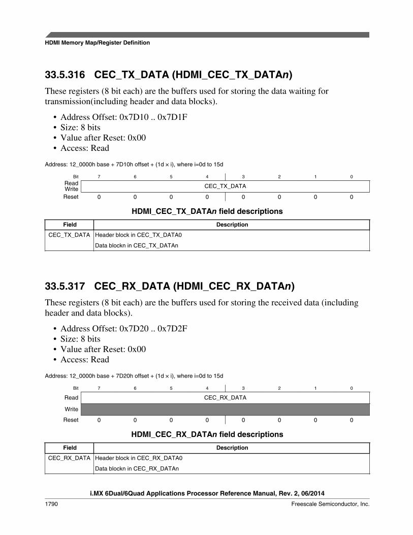
33.5.316 CEC_TX_DATA (HDMI_CEC_TX_DATAn)These registers (8 bit each) are the buffers used for storing the data waiting fortransmission(including header and data blocks).
• Address Offset: 0x7D10 .. 0x7D1F• Size: 8 bits• Value after Reset: 0x00• Access: Read
Address: 12_0000h base + 7D10h offset + (1d " i), where i=0d to 15d
Bit 7 6 5 4 3 2 1 0
Read CEC_TX_DATAWriteReset 0 0 0 0 0 0 0 0
HDMI_CEC_TX_DATAn field descriptions
Field Description
CEC_TX_DATA Header block in CEC_TX_DATA0
Data blockn in CEC_TX_DATAn
33.5.317 CEC_RX_DATA (HDMI_CEC_RX_DATAn)These registers (8 bit each) are the buffers used for storing the received data (includingheader and data blocks).
• Address Offset: 0x7D20 .. 0x7D2F• Size: 8 bits• Value after Reset: 0x00• Access: Read
Address: 12_0000h base + 7D20h offset + (1d " i), where i=0d to 15d
Bit 7 6 5 4 3 2 1 0
Read CEC_RX_DATA
Write
Reset 0 0 0 0 0 0 0 0
HDMI_CEC_RX_DATAn field descriptions
Field Description
CEC_RX_DATA Header block in CEC_RX_DATA0
Data blockn in CEC_RX_DATAn
HDMI Memory Map/Register Definition
i.MX 6Dual/6Quad Applications Processor Reference Manual, Rev. 2, 06/2014
1790 Freescale Semiconductor, Inc.
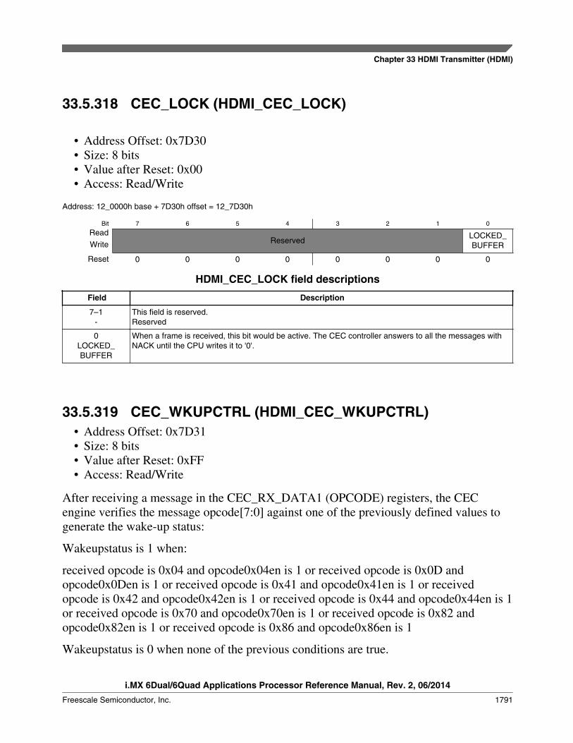
33.5.318 CEC_LOCK (HDMI_CEC_LOCK)
• Address Offset: 0x7D30• Size: 8 bits• Value after Reset: 0x00• Access: Read/Write
Address: 12_0000h base + 7D30h offset = 12_7D30h
Bit 7 6 5 4 3 2 1 0
ReadReserved
LOCKED_BUFFERWrite
Reset 0 0 0 0 0 0 0 0
HDMI_CEC_LOCK field descriptions
Field Description
7–1-
This field is reserved.Reserved
0LOCKED_BUFFER
When a frame is received, this bit would be active. The CEC controller answers to all the messages withNACK until the CPU writes it to '0'.
33.5.319 CEC_WKUPCTRL (HDMI_CEC_WKUPCTRL)• Address Offset: 0x7D31• Size: 8 bits• Value after Reset: 0xFF• Access: Read/Write
After receiving a message in the CEC_RX_DATA1 (OPCODE) registers, the CECengine verifies the message opcode[7:0] against one of the previously defined values togenerate the wake-up status:
Wakeupstatus is 1 when:
received opcode is 0x04 and opcode0x04en is 1 or received opcode is 0x0D andopcode0x0Den is 1 or received opcode is 0x41 and opcode0x41en is 1 or receivedopcode is 0x42 and opcode0x42en is 1 or received opcode is 0x44 and opcode0x44en is 1or received opcode is 0x70 and opcode0x70en is 1 or received opcode is 0x82 andopcode0x82en is 1 or received opcode is 0x86 and opcode0x86en is 1
Wakeupstatus is 0 when none of the previous conditions are true.
Chapter 33 HDMI Transmitter (HDMI)
i.MX 6Dual/6Quad Applications Processor Reference Manual, Rev. 2, 06/2014
Freescale Semiconductor, Inc. 1791
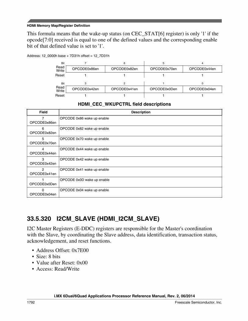
This formula means that the wake-up status (on CEC_STAT[6] register) is only '1' if theopcode[7:0] received is equal to one of the defined values and the corresponding enablebit of that defined value is set to '1'.
Address: 12_0000h base + 7D31h offset = 12_7D31h
Bit 7 6 5 4
Read OPCODE0x86en OPCODE0x82en OPCODE0x70en OPCODE0x44enWriteReset 1 1 1 1
Bit 3 2 1 0
Read OPCODE0x42en OPCODE0x41en OPCODE0x0Den OPCODE0x04enWriteReset 1 1 1 1
HDMI_CEC_WKUPCTRL field descriptions
Field Description
7OPCODE0x86en
OPCODE 0x86 wake up enable
6OPCODE0x82en
OPCODE 0x82 wake up enable
5OPCODE0x70en
OPCODE 0x70 wake up enable
4OPCODE0x44en
OPCODE 0x44 wake up enable
3OPCODE0x42en
OPCODE 0x42 wake up enable
2OPCODE0x41en
OPCODE 0x41 wake up enable
1OPCODE0x0Den
OPCODE 0x0D wake up enable
0OPCODE0x04en
OPCODE 0x04 wake up enable
33.5.320 I2CM_SLAVE (HDMI_I2CM_SLAVE)I2C Master Registers (E-DDC) registers are responsible for the Master's coordinationwith the Slave, by coordinating the Slave address, data identification, transaction status,acknowledgement, and reset functions.
• Address Offset: 0x7E00• Size: 8 bits• Value after Reset: 0x00• Access: Read/Write
HDMI Memory Map/Register Definition
i.MX 6Dual/6Quad Applications Processor Reference Manual, Rev. 2, 06/2014
1792 Freescale Semiconductor, Inc.
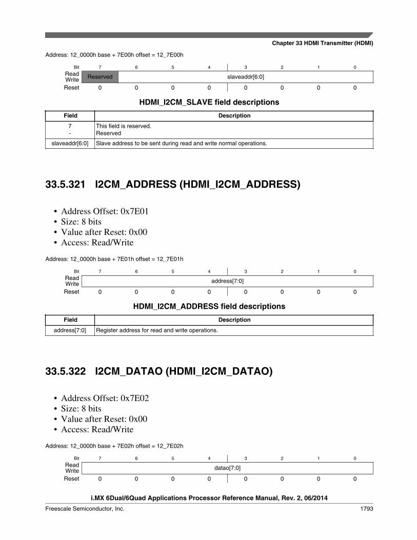
Address: 12_0000h base + 7E00h offset = 12_7E00h
Bit 7 6 5 4 3 2 1 0
Read Reserved slaveaddr[6:0]WriteReset 0 0 0 0 0 0 0 0
HDMI_I2CM_SLAVE field descriptions
Field Description
7-
This field is reserved.Reserved
slaveaddr[6:0] Slave address to be sent during read and write normal operations.
33.5.321 I2CM_ADDRESS (HDMI_I2CM_ADDRESS)
• Address Offset: 0x7E01• Size: 8 bits• Value after Reset: 0x00• Access: Read/Write
Address: 12_0000h base + 7E01h offset = 12_7E01h
Bit 7 6 5 4 3 2 1 0
Read address[7:0]WriteReset 0 0 0 0 0 0 0 0
HDMI_I2CM_ADDRESS field descriptions
Field Description
address[7:0] Register address for read and write operations.
33.5.322 I2CM_DATAO (HDMI_I2CM_DATAO)
• Address Offset: 0x7E02• Size: 8 bits• Value after Reset: 0x00• Access: Read/Write
Address: 12_0000h base + 7E02h offset = 12_7E02h
Bit 7 6 5 4 3 2 1 0
Read datao[7:0]WriteReset 0 0 0 0 0 0 0 0
Chapter 33 HDMI Transmitter (HDMI)
i.MX 6Dual/6Quad Applications Processor Reference Manual, Rev. 2, 06/2014
Freescale Semiconductor, Inc. 1793
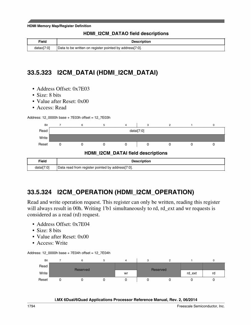
HDMI_I2CM_DATAO field descriptions
Field Description
datao[7:0] Data to be written on register pointed by address[7:0].
33.5.323 I2CM_DATAI (HDMI_I2CM_DATAI)
• Address Offset: 0x7E03• Size: 8 bits• Value after Reset: 0x00• Access: Read
Address: 12_0000h base + 7E03h offset = 12_7E03h
Bit 7 6 5 4 3 2 1 0
Read datai[7:0]
Write
Reset 0 0 0 0 0 0 0 0
HDMI_I2CM_DATAI field descriptions
Field Description
datai[7:0] Data read from register pointed by address[7:0].
33.5.324 I2CM_OPERATION (HDMI_I2CM_OPERATION)Read and write operation request. This register can only be written, reading this registerwill always result in 00h. Writing 1'b1 simultaneously to rd, rd_ext and wr requests isconsidered as a read (rd) request.
• Address Offset: 0x7E04• Size: 8 bits• Value after Reset: 0x00• Access: Write
Address: 12_0000h base + 7E04h offset = 12_7E04h
Bit 7 6 5 4 3 2 1 0
ReadReserved Reserved
Write wr rd_ext rd
Reset 0 0 0 0 0 0 0 0
HDMI Memory Map/Register Definition
i.MX 6Dual/6Quad Applications Processor Reference Manual, Rev. 2, 06/2014
1794 Freescale Semiconductor, Inc.
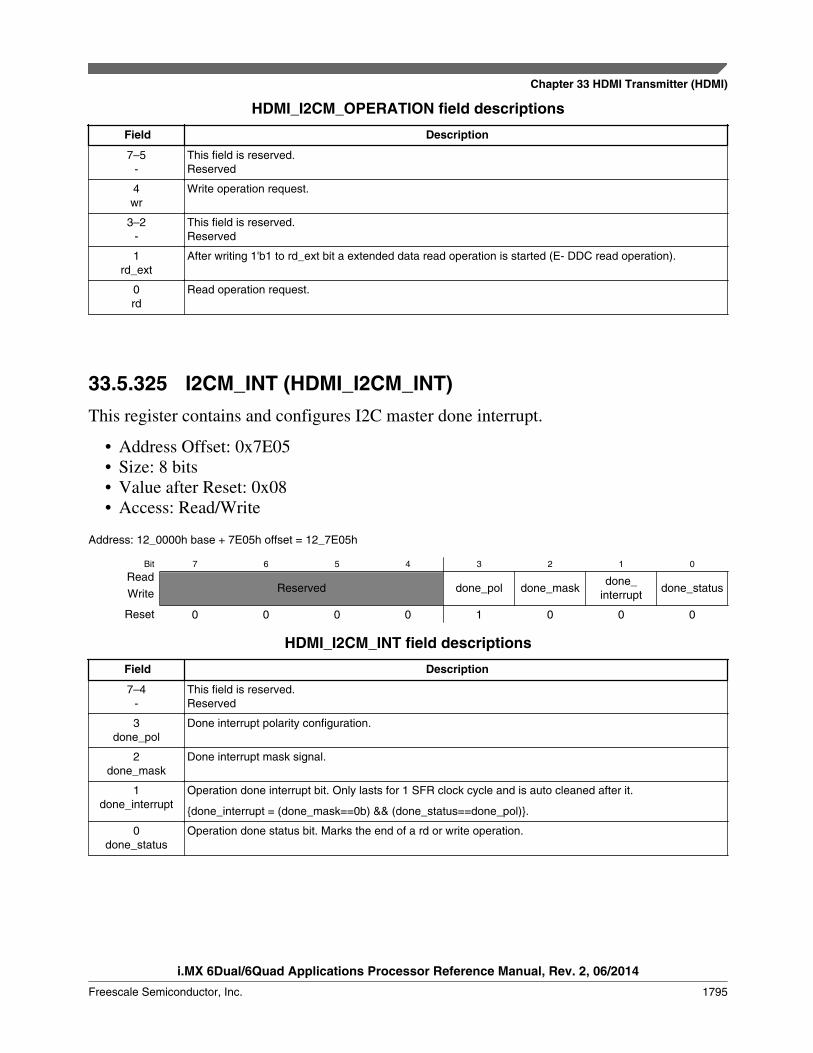
HDMI_I2CM_OPERATION field descriptions
Field Description
7–5-
This field is reserved.Reserved
4wr
Write operation request.
3–2-
This field is reserved.Reserved
1rd_ext
After writing 1'b1 to rd_ext bit a extended data read operation is started (E- DDC read operation).
0rd
Read operation request.
33.5.325 I2CM_INT (HDMI_I2CM_INT)This register contains and configures I2C master done interrupt.
• Address Offset: 0x7E05• Size: 8 bits• Value after Reset: 0x08• Access: Read/Write
Address: 12_0000h base + 7E05h offset = 12_7E05h
Bit 7 6 5 4 3 2 1 0
ReadReserved done_pol done_mask
done_interrupt
done_statusWrite
Reset 0 0 0 0 1 0 0 0
HDMI_I2CM_INT field descriptions
Field Description
7–4-
This field is reserved.Reserved
3done_pol
Done interrupt polarity configuration.
2done_mask
Done interrupt mask signal.
1done_interrupt
Operation done interrupt bit. Only lasts for 1 SFR clock cycle and is auto cleaned after it.
{done_interrupt = (done_mask==0b) && (done_status==done_pol)}.
0done_status
Operation done status bit. Marks the end of a rd or write operation.
Chapter 33 HDMI Transmitter (HDMI)
i.MX 6Dual/6Quad Applications Processor Reference Manual, Rev. 2, 06/2014
Freescale Semiconductor, Inc. 1795
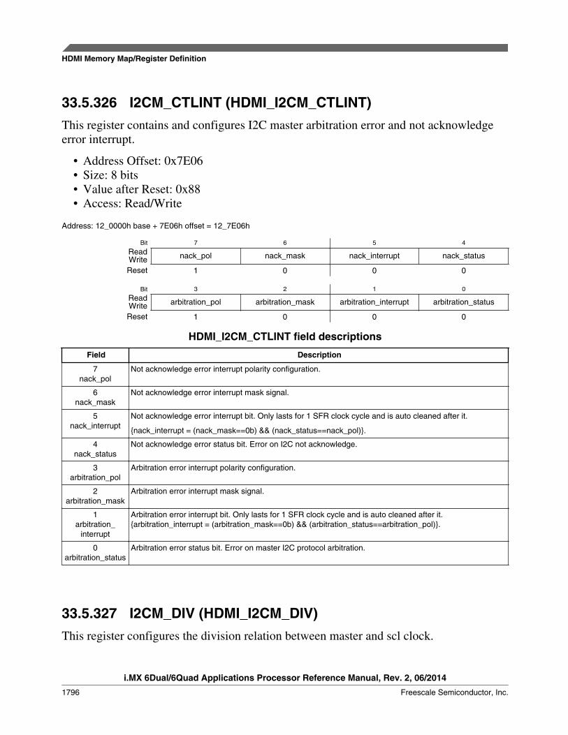
33.5.326 I2CM_CTLINT (HDMI_I2CM_CTLINT)This register contains and configures I2C master arbitration error and not acknowledgeerror interrupt.
• Address Offset: 0x7E06• Size: 8 bits• Value after Reset: 0x88• Access: Read/Write
Address: 12_0000h base + 7E06h offset = 12_7E06h
Bit 7 6 5 4
Read nack_pol nack_mask nack_interrupt nack_statusWriteReset 1 0 0 0
Bit 3 2 1 0
Read arbitration_pol arbitration_mask arbitration_interrupt arbitration_statusWriteReset 1 0 0 0
HDMI_I2CM_CTLINT field descriptions
Field Description
7nack_pol
Not acknowledge error interrupt polarity configuration.
6nack_mask
Not acknowledge error interrupt mask signal.
5nack_interrupt
Not acknowledge error interrupt bit. Only lasts for 1 SFR clock cycle and is auto cleaned after it.
{nack_interrupt = (nack_mask==0b) && (nack_status==nack_pol)}.
4nack_status
Not acknowledge error status bit. Error on I2C not acknowledge.
3arbitration_pol
Arbitration error interrupt polarity configuration.
2arbitration_mask
Arbitration error interrupt mask signal.
1arbitration_
interrupt
Arbitration error interrupt bit. Only lasts for 1 SFR clock cycle and is auto cleaned after it.{arbitration_interrupt = (arbitration_mask==0b) && (arbitration_status==arbitration_pol)}.
0arbitration_status
Arbitration error status bit. Error on master I2C protocol arbitration.
33.5.327 I2CM_DIV (HDMI_I2CM_DIV)This register configures the division relation between master and scl clock.
HDMI Memory Map/Register Definition
i.MX 6Dual/6Quad Applications Processor Reference Manual, Rev. 2, 06/2014
1796 Freescale Semiconductor, Inc.

• Address Offset: 0x7E07• Size: 8 bits• Value after Reset: 0x0B• Access: Read/Write
Address: 12_0000h base + 7E07h offset = 12_7E07h
Bit 7 6 5 4 3 2 1 0
ReadReserved
fast_std_mode
ReservedWrite
Reset 0 0 0 0 1 0 1 1
HDMI_I2CM_DIV field descriptions
Field Description
7–4-
This field is reserved.Reserved
3fast_std_mode
Sets the I2C Master to work in Fast Mode or Standard Mode:
1 Fast Mode0 Standard Mode
- This field is reserved.Reserved
33.5.328 I2CM_SEGADDR (HDMI_I2CM_SEGADDR)This register configures the segment address for extended RD/WR destination.
• Address Offset: 0x7E08• Size: 8 bits• Value after Reset: 0x00• Access: Read/Write
Address: 12_0000h base + 7E08h offset = 12_7E08h
Bit 7 6 5 4 3 2 1 0
Read Reserved SEGADDRWriteReset 0 0 0 0 0 0 0 0
HDMI_I2CM_SEGADDR field descriptions
Field Description
7-
This field is reserved.Reserved
SEGADDR E-DDC Extended read segment address
Chapter 33 HDMI Transmitter (HDMI)
i.MX 6Dual/6Quad Applications Processor Reference Manual, Rev. 2, 06/2014
Freescale Semiconductor, Inc. 1797
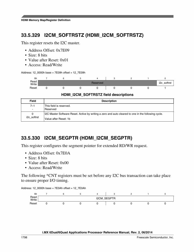
33.5.329 I2CM_SOFTRSTZ (HDMI_I2CM_SOFTRSTZ)This register resets the I2C master.
• Address Offset: 0x7E09• Size: 8 bits• Value after Reset: 0x01• Access: Read/Write
Address: 12_0000h base + 7E09h offset = 12_7E09h
Bit 7 6 5 4 3 2 1 0
Read Reserved i2c_softrstWriteReset 0 0 0 0 0 0 0 1
HDMI_I2CM_SOFTRSTZ field descriptions
Field Description
7–1-
This field is reserved.Reserved
0i2c_softrst
I2C Master Software Reset. Active by writing a zero and auto cleared to one in the following cycle.
Value after Reset: 1b
33.5.330 I2CM_SEGPTR (HDMI_I2CM_SEGPTR)This register configures the segment pointer for extended RD/WR request.
• Address Offset: 0x7E0A• Size: 8 bits• Value after Reset: 0x00• Access: Read/Write
The following *CNT registers must be set before any I2C bus transaction can take placeto ensure proper I/O timing.
Address: 12_0000h base + 7E0Ah offset = 12_7E0Ah
Bit 7 6 5 4 3 2 1 0
Read I2CM_SEGPTRWriteReset 0 0 0 0 0 0 0 0
HDMI Memory Map/Register Definition
i.MX 6Dual/6Quad Applications Processor Reference Manual, Rev. 2, 06/2014
1798 Freescale Semiconductor, Inc.

HDMI_I2CM_SEGPTR field descriptions
Field Description
I2CM_SEGPTR I2CM_SEGPTR is used for EDID reading operations, particularly for the Extended Data Read Operation(See I2C Master Interface Extended Read Mode ") which is used for Enhanced DDC. This is all describedin the VESA Enhanced Display Data Channel Standard v1.1 spec. (addresses A0h/A1h pairs and asegment pointer - 60h).
33.5.331 I2CM_SS_SCL_HCNT_1_ADDR(HDMI_I2CM_SS_SCL_HCNT_1_ADDR)
• Address Offset: 0x7E0B• Size: 8 bits• Value after Reset: 0x00• Access: Read/Write
Address: 12_0000h base + 7E0Bh offset = 12_7E0Bh
Bit 7 6 5 4 3 2 1 0
Read i2cmp_ss_scl_hcnt[15:8]WriteReset 0 0 0 0 0 0 0 0
HDMI_I2CM_SS_SCL_HCNT_1_ADDR field descriptions
Field Description
i2cmp_ss_scl_hcnt[15:8]
Value after Reset: 8'h00
33.5.332 I2CM_SS_SCL_HCNT_0_ADDR(HDMI_I2CM_SS_SCL_HCNT_0_ADDR)
• Address Offset: 0x7E0C• Size: 8 bits• Value after Reset: 0x6C• Access: Read/Write
Address: 12_0000h base + 7E0Ch offset = 12_7E0Ch
Bit 7 6 5 4 3 2 1 0
Read i2cmp_ss_scl_hcnt[7:0]WriteReset 0 1 1 0 1 1 0 0
Chapter 33 HDMI Transmitter (HDMI)
i.MX 6Dual/6Quad Applications Processor Reference Manual, Rev. 2, 06/2014
Freescale Semiconductor, Inc. 1799

HDMI_I2CM_SS_SCL_HCNT_0_ADDR field descriptions
Field Description
i2cmp_ss_scl_hcnt[7:0]
Value after Reset: 8'h6C
33.5.333 I2CM_SS_SCL_LCNT_1_ADDR(HDMI_I2CM_SS_SCL_LCNT_1_ADDR)
• Address Offset: 0x7E0D• Size: 8 bits• Value after Reset: 0x00• Access: Read/Write
Address: 12_0000h base + 7E0Dh offset = 12_7E0Dh
Bit 7 6 5 4 3 2 1 0
Read i2cmp_ss_scl_lcnt[15:8]WriteReset 0 0 0 0 0 0 0 0
HDMI_I2CM_SS_SCL_LCNT_1_ADDR field descriptions
Field Description
i2cmp_ss_scl_lcnt[15:8]
Value after Reset: 8'h00
33.5.334 I2CM_SS_SCL_LCNT_0_ADDR(HDMI_I2CM_SS_SCL_LCNT_0_ADDR)
• Address Offset: 0x7E0E• Size: 8 bits• Value after Reset: 0x7F• Access: Read/Write
Address: 12_0000h base + 7E0Eh offset = 12_7E0Eh
Bit 7 6 5 4 3 2 1 0
Read i2cmp_ss_scl_lcnt[7:0]WriteReset 0 1 1 1 1 1 1 1
HDMI Memory Map/Register Definition
i.MX 6Dual/6Quad Applications Processor Reference Manual, Rev. 2, 06/2014
1800 Freescale Semiconductor, Inc.

HDMI_I2CM_SS_SCL_LCNT_0_ADDR field descriptions
Field Description
i2cmp_ss_scl_lcnt[7:0]
Value after Reset: 8'h7F
33.5.335 I2CM_FS_SCL_HCNT_1_ADDR(HDMI_I2CM_FS_SCL_HCNT_1_ADDR)
• Address Offset: 0x7E0F• Size: 8 bits• Value after Reset: 0x00• Access: Read/Write
Address: 12_0000h base + 7E0Fh offset = 12_7E0Fh
Bit 7 6 5 4 3 2 1 0
Read i2cmp_fs_scl_hcnt[15:8]WriteReset 0 0 0 0 0 0 0 0
HDMI_I2CM_FS_SCL_HCNT_1_ADDR field descriptions
Field Description
i2cmp_fs_scl_hcnt[15:8]
Value after Reset: 8'h00
33.5.336 I2CM_FS_SCL_HCNT_0_ADDR(HDMI_I2CM_FS_SCL_HCNT_0_ADDR)
• Address Offset: 0x7E10• Size: 8 bits• Value after Reset: 0x11• Access: Read/Write
Address: 12_0000h base + 7E10h offset = 12_7E10h
Bit 7 6 5 4 3 2 1 0
Read i2cmp_fs_scl_hcnt[7:0]WriteReset 0 0 0 1 0 0 0 1
Chapter 33 HDMI Transmitter (HDMI)
i.MX 6Dual/6Quad Applications Processor Reference Manual, Rev. 2, 06/2014
Freescale Semiconductor, Inc. 1801

HDMI_I2CM_FS_SCL_HCNT_0_ADDR field descriptions
Field Description
i2cmp_fs_scl_hcnt[7:0]
Value after Reset: 8'h11
33.5.337 I2CM_FS_SCL_LCNT_1_ADDR(HDMI_I2CM_FS_SCL_LCNT_1_ADDR)
• Address Offset: 0x7E11• Size: 8 bits• Value after Reset: 0x00• Access: Read/Write
Address: 12_0000h base + 7E11h offset = 12_7E11h
Bit 7 6 5 4 3 2 1 0
Read i2cmp_fs_scl_lcnt[15:8]WriteReset 0 0 0 0 0 0 0 0
HDMI_I2CM_FS_SCL_LCNT_1_ADDR field descriptions
Field Description
i2cmp_fs_scl_lcnt[15:8]
Value after Reset: 8'h00
33.5.338 I2CM_FS_SCL_LCNT_0_ADDR(HDMI_I2CM_FS_SCL_LCNT_0_ADDR)
• Address Offset: 0x7E12• Size: 8 bits• Value after Reset: 0x24• Access: Read/Write
Address: 12_0000h base + 7E12h offset = 12_7E12h
Bit 7 6 5 4 3 2 1 0
Read i2cmp_fs_scl_lcnt[7:0]WriteReset 0 0 1 0 0 1 0 0
HDMI Memory Map/Register Definition
i.MX 6Dual/6Quad Applications Processor Reference Manual, Rev. 2, 06/2014
1802 Freescale Semiconductor, Inc.

HDMI_I2CM_FS_SCL_LCNT_0_ADDR field descriptions
Field Description
i2cmp_fs_scl_lcnt[7:0]
Value after Reset: 8'h24
33.5.339 BASE_POINTER_ADDR (HDMI_BASE_POINTER_ADDR)The I2C Slave Registers allow register memory pagination, and function in theincremental burst operation mode that increases the data throughput when consecutiveaddressed registers need to be read or write.
The I2C base pointer operation mode is a aimed to allow register memory pagination. Aslong as this operational mode is enabled the value written to this register will be used asthe seven most significant bits of the internal Special Function Register address interface(sfraddr[14:8]) for all read or write operations. I2C data transfer protocol used shall bethe 7-bit addressed as defined in the section 9 of the I2C-bus Specification, version 2.1.
• Address Offset: 0x7F00• Size: 8 bits• Value after Reset: 0x00• Access: Read/Write
Address: 12_0000h base + 7F00h offset = 12_7F00h
Bit 7 6 5 4 3 2 1 0
Read en_base_pointer_addr
base_pointer_base_addr[6:0]Write
Reset 0 0 0 0 0 0 0 0
HDMI_BASE_POINTER_ADDR field descriptions
Field Description
7en_base_
pointer_addr
Enables the base pointer operation mode.
base_pointer_base_addr[6:0]
Defines the base address for base pointer operation mode. They represent the address bits [14:8]
Chapter 33 HDMI Transmitter (HDMI)
i.MX 6Dual/6Quad Applications Processor Reference Manual, Rev. 2, 06/2014
Freescale Semiconductor, Inc. 1803