chapter 36 image formation. summary: mirrors sign conventions: + on the left - on the right convex...
TRANSCRIPT

Chapter 36
Image Formation
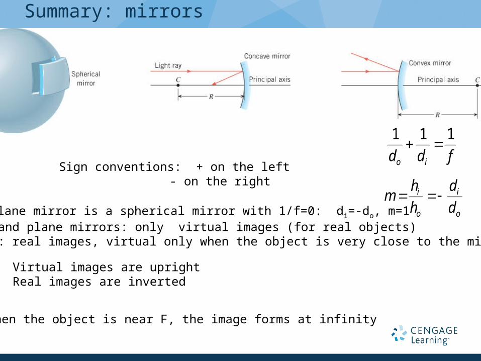
Summary: mirrors
fdd io
111
o
i
o
i
d
d
h
hm
Sign conventions: + on the left - on the right
Convex and plane mirrors: only virtual images (for real objects)Concave: real images, virtual only when the object is very close to the mirror (do<f)
Virtual images are uprightReal images are inverted
A plane mirror is a spherical mirror with 1/f=0: di=-do, m=1
When the object is near F, the image forms at infinity

25.3 The Formation of Images by a Plane Mirror
Conceptual Example 1 Full-Length Versus Half-Length Mirrors
What is the minimum mirror height necessary for her to see her fullimage?

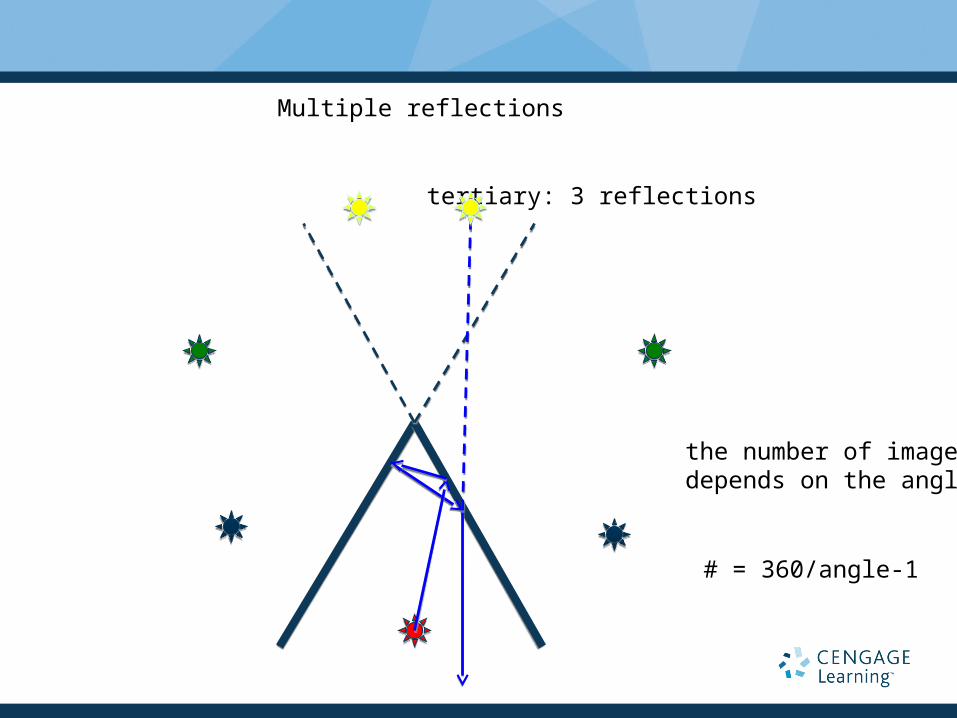
Multiple reflections
primary
secondary
tertiary
object

Multiple reflections
secondary: 2 reflections
Multiple reflections
tertiary: 3 reflections
the number of imagesdepends on the angle
# = 360/angle-1
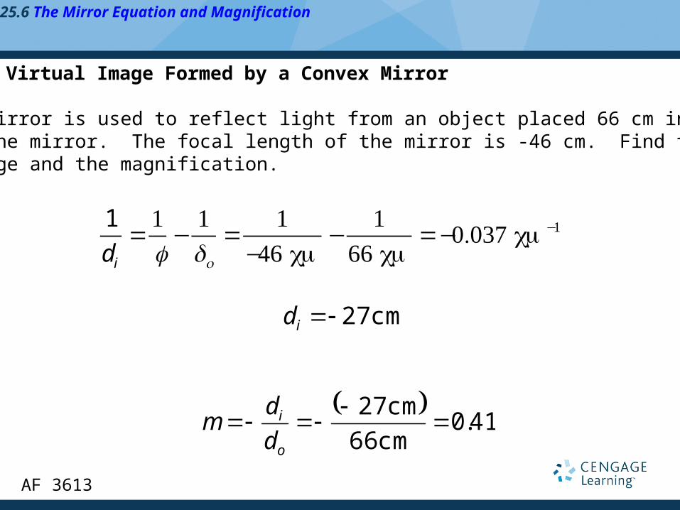
25.6 The Mirror Equation and Magnification
Example 5 A Virtual Image Formed by a Convex Mirror
A convex mirror is used to reflect light from an object placed 66 cm infront of the mirror. The focal length of the mirror is -46 cm. Find the locationof the image and the magnification.
1
di1f−
1do
1
−46 cm−
166 cm
−0.037 cm −1
cm 27id
41.0
cm 66
cm 27
o
i
d
dm
AF 3613
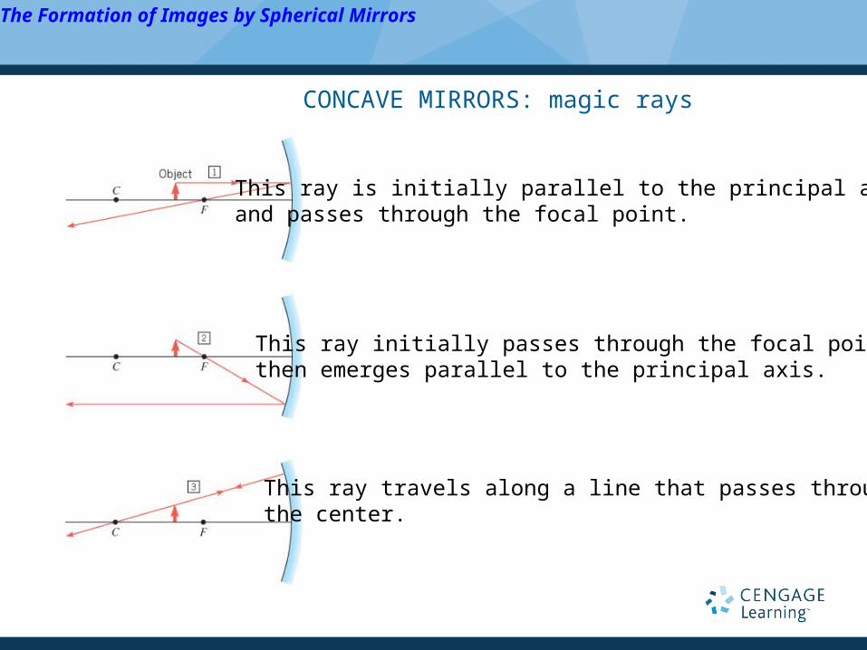
The Formation of Images by Spherical Mirrors
CONCAVE MIRRORS: magic rays
This ray is initially parallel to the principal axisand passes through the focal point.
This ray initially passes through the focal point,then emerges parallel to the principal axis.
This ray travels along a line that passes through the center.
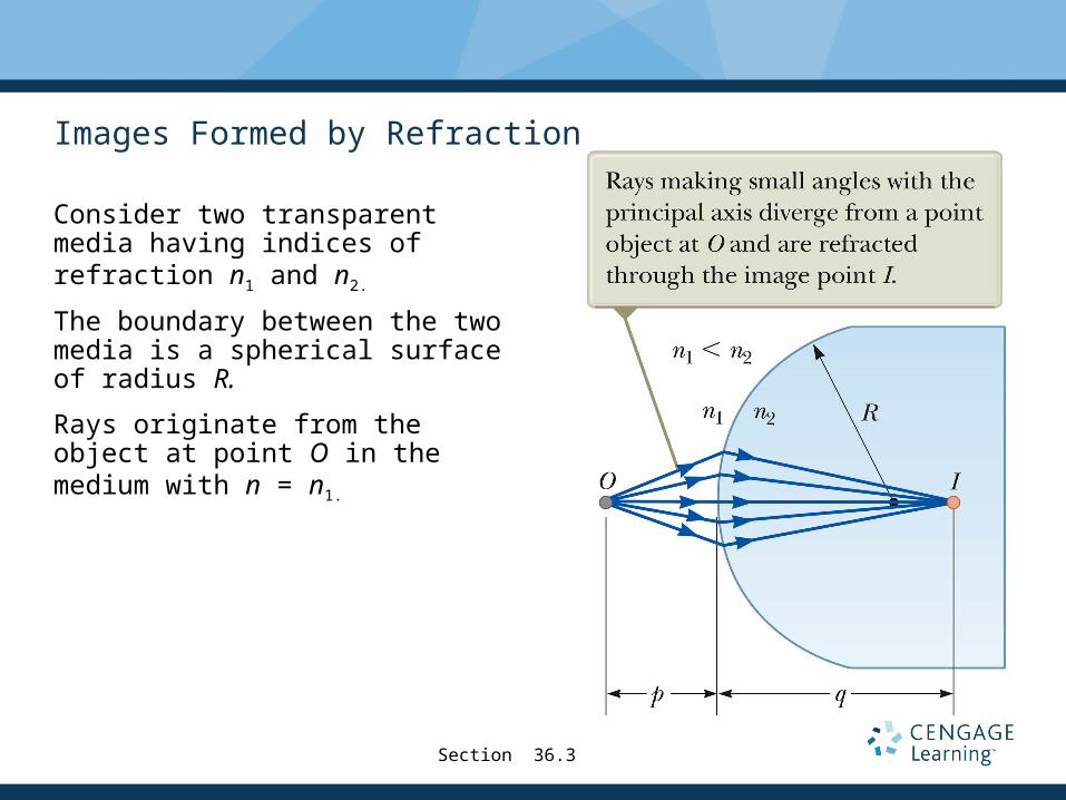
Images Formed by Refraction
Consider two transparent media having indices of refraction n1 and n2.
The boundary between the two media is a spherical surface of radius R.
Rays originate from the object at point O in the medium with n = n1.
Section 36.3
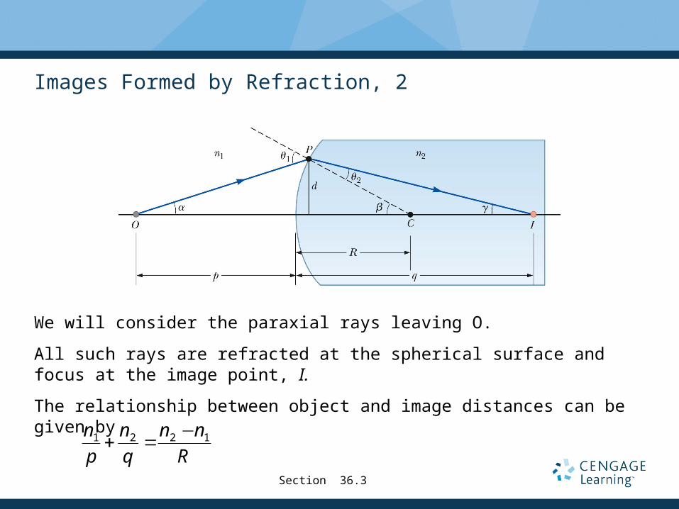
Images Formed by Refraction, 2
We will consider the paraxial rays leaving O.
All such rays are refracted at the spherical surface and focus at the image point, I.
The relationship between object and image distances can be given by
1 2 2 1n n n n
p q R
−+ =
Section 36.3

Images Formed by Refraction, 2
proof: ALL SMALL ANGLES: sinθ=tanθ=θ
n1θ1=n2θ2
OPCα+β=θ1
CPI γ+θ2=βθ2=β-γ
α=d/p; β=d/R; γ=d/q
1 2 2 1n n n n
p q R
−+ =
Section 36.3
n1(α+β)=n2(β-γ)

Images Formed by Refraction, 3
The side of the surface in which the light rays originate is defined as the front side.
The other side is called the back side.
Real images are formed by refraction in the back of the surface.
Because of this, the sign conventions for q and R for refracting surfaces are opposite those for reflecting surfaces.
Section 36.3

Sign Conventions for Refracting Surfaces
Section 36.3
For reflection and refraction: negative location = virtual

Flat Refracting Surfaces
If a refracting surface is flat, then R is infinite.
Then q = -(n2 / n1)p
The image formed by a flat refracting surface is on the same side of the surface as the object.
A virtual image is formed.
Section 36.3AF 3618
n1
p+n2
q=n2 −n1R
=0

Images Formed by Thin Lenses
Lenses are commonly used to form images by refraction.
Lenses are used in optical instruments.
Cameras
Telescopes
Microscopes
Light passing through a lens experiences refraction at two surfaces.
The image formed by one refracting surface serves as the object for the second surface.
Section 36.4

Thin Lens Equation
The relationship among the focal length, the object distance and the image distance is the same as for a mirror.
1 1 1
ƒp q+ =
Section 36.4
p q

Notes on Focal Length and Focal Point of a Thin Lens
Because light can travel in either direction through a lens, each lens has two focal points.
One focal point is for light passing in one direction through the lens and one is for light traveling in the opposite direction.
However, there is only one focal length.
Each focal point is located the same distance from the lens.
Section 36.4

Focal Length of a Converging Lens
The parallel rays pass through the lens and converge at the focal point.
The parallel rays can come from the left or right of the lens.
Section 36.4
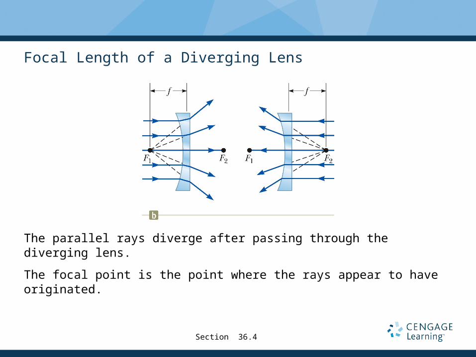
Focal Length of a Diverging Lens
The parallel rays diverge after passing through the diverging lens.
The focal point is the point where the rays appear to have originated.
Section 36.4
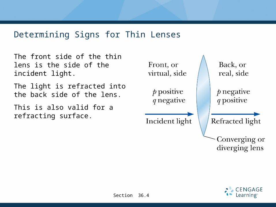
Determining Signs for Thin Lenses
The front side of the thin lens is the side of the incident light.
The light is refracted into the back side of the lens.
This is also valid for a refracting surface.
Section 36.4

Sign Conventions for Thin Lenses
Section 36.4

Magnification of Images Through a Thin Lens
The lateral magnification of the image is
When M is positive, the image is upright and on the same side of the lens as the object.
When M is negative, the image is inverted and on the side of the lens opposite the object.
'h qM
h p= =−
Section 36.4

Thin Lens Shapes
These are examples of converging lenses.
They have positive focal lengths.
They are thickest in the middle.
Section 36.4

More Thin Lens Shapes
These are examples of diverging lenses.
They have negative focal lengths.
They are thickest at the edges.
Section 36.4

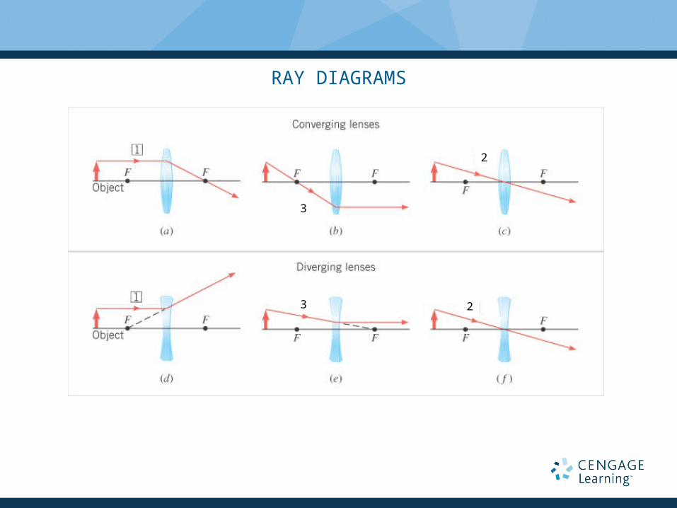
Ray Diagrams for Thin Lenses – Converging
Ray diagrams are convenient for locating the images formed by thin lenses or systems of lenses.
For a converging lens, the following three rays are drawn:
Ray 1 is drawn parallel to the principal axis and then passes through the focal point on the back side of the lens.
Ray 2 is drawn through the center of the lens and continues in a straight line.
Ray 3 is drawn through the focal point on the front of the lens (or as if coming from the focal point if p < ƒ) and emerges from the lens parallel to the principal axis.
Section 36.4
RAY DIAGRAMS
3
3 2
2
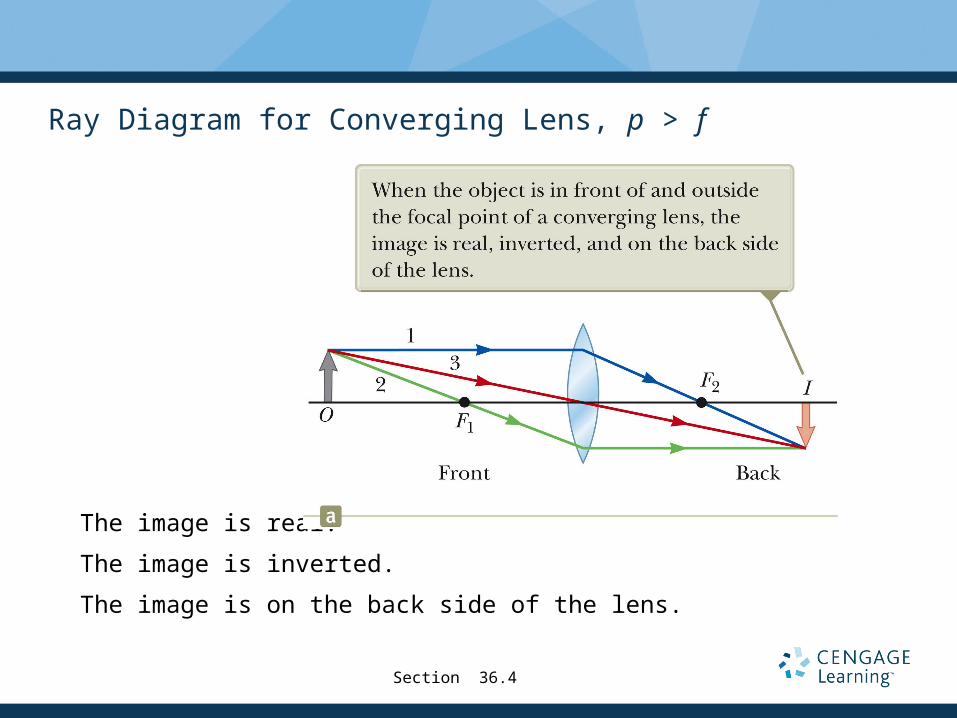
Ray Diagram for Converging Lens, p > f
The image is real.
The image is inverted.
The image is on the back side of the lens.
Section 36.4

Ray Diagram for Converging Lens, p < f
The image is virtual.
The image is upright.
The image is larger than the object.
The image is on the front side of the lens.Section 36.4
AF 3626

Ray Diagrams for Thin Lenses – Diverging
For a diverging lens, the following three rays are drawn:
Ray 1 is drawn parallel to the principal axis and emerges directed away from the focal point on the front side of the lens.
Ray 2 is drawn through the center of the lens and continues in a straight line.
Ray 3 is drawn in the direction toward the focal point on the back side of the lens and emerges from the lens parallel to the principal axis.
Section 36.4

Ray Diagram for Diverging Lens
The image is virtual.
The image is upright.
The image is smaller.
The image is on the front side of the lens.
Section 36.4

Image Summary
For a converging lens, when the object distance is greater than the focal length, (p > ƒ)
The image is real and inverted.
For a converging lens, when the object is between the focal point and the lens, (p < ƒ)
The image is virtual and upright.
For a diverging lens, the image is always virtual and upright.
This is regardless of where the object is placed.
Section 36.4

Example 9 The Real Image Formed by a Camera Lens
A 1.70-m tall person is standing 2.50 m in front of a camera. Thecamera uses a converging lens whose focal length is 0.0500 m. (a)Find the image distance and determine whether the image isreal or virtual. (b) Find the magnification and height of the imageon the film.
1
q=1f−1p=
10.0500 m
−1
2.50 m=19.6 m−1(a)
q =0.0510 m real image
(b)
( )( ) m 0347.0m 50.20204.0 −=−== oi mhh