chapter 4 concrete - globalsecurity.org · concrete 4-1 chapter 4 concrete this chapter discusses...
TRANSCRIPT

RETURN TO TOC
Chapter 4
Concrete
This chapter discusses the testing of both fresh and hardened concrete andthe construction materials used to mix it. These tests are performed toensure that the concrete meets design requirements before it is poured.Since there are many factors that contribute to the success of the finishedproduct, all test methods must adhere to ASTM standards.
Further information on concrete types, components, design, and uses inmilitary construction can be found in FM 5-428.
Concrete is one of the most economical, versatile, and universally usedconstruction materials. It is one of the few building materials that can beproduced by the user directly on the job to meet the specific requirements.Concrete is an artificial stone which, when first mixed, forms a plastic orputty-like mixture. This mixture can then be placed into a form and allowedto harden or cure for a prescribed length of time. When cured, the finishedconcrete is a hard, stone-like material. It is used for pavements, foundations,dams and retaining walls, bridges, and buildings of all types.
DESCRIPTION AND COMPONENTS
Concrete is a mixture of portland cement, fine and coarse aggregates,entrapped or entrained air, and water. During mixing, the cement, air, andwater form a fluid paste that contributes to thorough mixing and effectiveplacement of the concrete. The cement and water, when mixed, combinechemically to bind the aggregate particles together. This combining process—called hydration—results in a rapid development of strength in the first fewhours after mixing, followed by less rapid gains in strength during thefollowing weeks.
CEMENT
Cement is a substance that hardens with time and holds or entraps objects orparticles in a definite relation to each other. For concrete, portland cementusually is used.
Portland cement is a substance that when mixed with water, hardens andbinds objects or particles together to form concrete. This process beginsimmediately and continues as long as moisture and temperature conditionsare favorable. As hydration continues, concrete becomes harder and stronger.Most of the hydration takes place during the first 30 days. Hydration cancontinue well over 50 years but at a much slower rate. References to cementin this manual mean portland cement. The ASTM specifies eight common
SECTION I. CHARACTERISTICS AND IDENTIFICATION
Concrete 4-1

FM 5-472/NAVFAC MO 330/AFJMAN 32-1221(I)
types of portland cement (ASTM C 150-97). These are adequate for mostpurposes. The various types of portland cement are known as hydrauliccements because they are capable of hardening and developing strength in thepresence of water. These cements include—
• Type I. Cement used for general construction when special propertiesfor any other type are not required.
• Type IA. Air-entraining cement used for the same purposes as Type I,except that air entrainment is desired. Entrained air improvesworkability and provides resistance to frost action, freezing, andthawing.
• Type II. Cement used for general purposes, especially when moderatesulfate resistance or moderate heat of hydration is desired. It has alower heat of hydration than the normal Type I, generates heat at aslower rate, and has improved resistance to sulfate attack. Type IIcement is used in locations where a high temperature rise in theconcrete is objectionable, as in structures of considerable mass such aslarge piers, heavy abutments, and heavy retaining walls.
• Type IIA. Air-entraining cement used for the same purposes as TypeII, except that air entrainment is desired.
• Type III. Cement used when a high strength is needed quickly. Thismay be due to a demand for early use or in cold-weather constructionto reduce the period of protection against low or freezingtemperatures.
• Type IIIA. Air-entraining cement used for the same purposes as TypeIII, except that air entrainment is desired.
• Type IV. Cement used when a low heat of hydration is desired to keepthe amount and rate of heat generated to a minimum. Type IVcement develops strength at a slower rate than Type I cement buthelps prevent the development of high temperatures in the structurewith the attendant danger of thermal cracking later when it cools.
• Type V. Cement used when high sulfate resistance is desired.Sulfates react chemically with the cement compounds, causingundesirable expansion of the mixture. The sulfates may be present inthe water used to mix the concrete or may be created by sulfurousgases from nearby industrial areas. The principal source of sulfateattack, however, occurs on foundations and other concrete in contactwith the earth in certain regions and is caused by a reaction betweenthe groundwater (containing dissolved reactive minerals or acid) andthe hardened cement. Type V cement is low in calcium aluminate andis highly resistant to sulfate attack.
AIR-ENTRAINED CEMENT
Concrete made with air-entrained cement is resistant to severe frost actionand to salts used for ice and snow removal. In general, air entrainment maybe controlled to a much greater extent by using admixtures with normalcements during mixing. This combination results in concrete with tiny,distributed and separated air bubbles (up to millions per cubic foot). The
4-2 Concrete

FM 5-472/NAVFAC MO 330/AFJMAN 32-1221(I)
entrained air bubbles improve the workability of fresh concrete. Thesebubbles reduce the capillary and water-channel structure within water, whichprevents the buildup of damaging water. Air-entrained concrete has greatlyincreased durability in outdoor locations exposed to freezing weather. Each ofthe first three Types (I, II, and III) are available as air-entrained. To signifythis characteristic, a letter A is added after the type. For example, a Type IIcement with an air-entrained admixture is identified as Type IIA.
WATER
Water plays an important part in the concrete mix. Its principal uses are tomake the mix workable and to start the chemical reaction. Any material inthe water that retards or changes the reaction is detrimental. A good rule ofthumb is, "If it's good enough to drink, it may be used for concrete.”
Ordinary Water
The materials found in some types of water include organic compounds, oil,alkali, and acid. Each has an effect on the hydration process.
• Organic material and oil. These compounds tend to coat the aggregateand cement particles and prevent the full chemical action andadherence. The organic material may also react with the cement andcreate a weakened cementing action, thus contributing todeterioration and structural failure of the concrete.
• Alkalies, acids, and sulfates. Certain limiting amounts of thesechemical impurities in the water tend to react adversely with thecement. The result is inadequate cementing and weakened concrete.Water must be substantially free of these chemicals for use in concretemixing.
Sea Water
The salts in sea water are normally thought of as being corrosive. However,sea water is sometimes used for concrete mixing with satisfactory results. A10 to 20 percent loss in compressive strength can be expected when using thesame amount of sea water as fresh water. This can be compensated forsomewhat by reducing the water-cement ratio.
AGGREGATES
The aggregates commonly used for concrete are natural deposits of sand andgravel, where available, or crushed stone. Crushed aggregate may cost moreto produce; however, this may be the only way to obtain substantial quantitiesof large-sized stone. Artificial aggregates such as a blast-furnace slag orspecially burned shales and clays are used.
Aggregates are divided into the following types:
• Fine aggregate.
• Coarse aggregate.
When properly proportioned and mixed with cement, these two groups willyield an almost voidless stone that is strong and durable. Aggregate should beequal to or better in strength and durability than the hardened cement pasteif it is to withstand the design loads and effects of severe weather.
Concrete 4-3

FM 5-472/NAVFAC MO 330/AFJMAN 32-1221(I)
Fine Aggregates
Fine aggregates are the material that will pass a No. 4 sieve and will bepredominantly retained on a No. 200 sieve. To increase workability and foreconomy as reflected by using less cement, the fine aggregates should have arounded shape. Their purpose is to fill the voids between coarse-aggregateparticles and to modify the concrete’s workability. This workabilitycharacteristic is discussed more in the description of finished concrete.
Coarse Aggregates
Coarse aggregates are the material that will be retained on a No. 4 sieve. Indetermining the maximum size of coarse aggregate, other factors must also beconsidered. The coarser the aggregate used, the more economical the mix, asaggregate costs less than cement. Larger pieces offer less surface area of theparticles than an equivalent volume of small pieces. Using the largestpermissible maximum size of coarse aggregate permits a reduction in cementand water requirements. One restriction usually assigned to coarse aggregateis its maximum size. Large pieces can interlock and form arches orobstructions within a concrete form. This restricts the area below to a void orat best, fills the area below with the finer particles of sand and cement. Thisis either a weakened area or a cement-sand concentration that does not leaveenough mortar to coat the rest of the aggregate. The capacity of mixingequipment, the spacing of reinforcement, or the minimum width of formslimits the maximum aggregate size. A listing of maximum sizes of coarseaggregate is indicated in Section II of this chapter.
PROPERTIES OF CONCRETE
To combine the ingredients correctly and to form the required concrete, it isessential to know the required physical properties of both the plastic and thehardened concrete. The hardened concrete must have the followingproperties:
• Strength.
• Durability.
• Watertightness.
• Workability.
• Consistency.
• Uniformity.
The quality and character of the hardened concrete is greatly influenced bythe properties of the mix when it is plastic. To attain optimum quality, theplastic mix must be uniform, consistent, and workable. This permits placingthe concrete without developing segregation, honeycombing, or other defectsin filling the forms or in producing the desired smooth, hard, and resilientsurface.
STRENGTH
Strength is the concrete’s ability to resist a load in compression, bending, orshear (see Sections IV and V of this chapter). The desired design strength is
4-4 Concrete

FM 5-472/NAVFAC MO 330/AFJMAN 32-1221(I)
obtained by proportioning the mixture with correctly graded aggregates, anadequate amount of cement to coat the surface area of the particles, and theproper amount of mixing water. The most important influencing factor onstrength is the ratio of water to cement (W/C ratio). For plastic and workablemixes, lower values of the W/C ratio give higher strengths. Two and one-halfgallons of water is the minimum amount necessary to hydrate a sack of cementadequately.
This minimal amount of water is not sufficient to economically provide theneeded plasticity and workability for freshly mixed concrete. Additional watermust be added to the mixture to improve workability but must be minimized toobtain the desired strength with an economical cement content. Additionalwater thins the paste content and therefore coats more particles. This increasesthe yield from each sack of cement and produces a more economical mix.Excessive amounts of water (too high a W/C ratio) weakens the paste byallowing the cement particles to hydrate while suspended in water withoutbeing in contact with the aggregate or other cement particles. This watereventually evaporates, leaving holes or voids in the hardened concrete thatcause additional losses in strength. Minimum and maximum amounts of waterare specified to assure an economical mix with no loss in strength. This rangesfrom 4 to 8 gallons per sack of cement (94 pounds).
DURABILITY
Durability is the concrete’s ability to resist the elements of weathering andloading. The primary elements affecting concrete are wind, abrasion, freezingand thawing, wetting and drying, and the chemical action of salts. As the W/Cratio is increased (4 gallons per sack), more voids develop in the hardenedconcrete. Therefore, more surface area is available for the detrimentalelements to attack, resulting in a less-durable structure. Weak or easilycrushed rock or other mineral particles that break down under applied loadsintroduce internal stresses that cause a breakdown of the concrete. Rocks ormineral particles that are absorptive or susceptible to swelling whensaturated will deteriorate when subjected to severe weather conditions.Freezing moisture causes expansion stresses that can easily ruptureabsorptive rocks. Rocks swollen from the sun's radiant heat and thensubjected to shrinkage from sudden cooling by rain or temperature drop maybreak down from the severe weathering. The concrete aggregate mustwithstand all these forces of nature.
WATERTIGHTNESS
A well-mixed, well-proportioned concrete presents a solid surface to preventwater penetration. Superficial voids permit some water to enter below theconcrete’s surface but the water soon meets a dense, solid mass that preventsfurther penetration. As the W/C ratio is increased, the excess water formsmore holes or voids that eventually interconnect to form channels into andthroughout the concrete. The end result is a more porous concrete thatpermits water to pass. For watertightness, 6 gallons of water or less per sackof cement will meet the requirement.
Concrete 4-5

FM 5-472/NAVFAC MO 330/AFJMAN 32-1221(I)
WORKABILITY
Workability is the relative ease of difficulty of placing and consolidatingconcrete. It is controlled primarily by the amount of each aggregate inproportion to a given quantity of cement paste. As more aggregate is added to agiven amount of paste, the mixture becomes harsh and stiff. The increasedstiffness makes it more difficult to work the concrete into the forms and aroundthe reinforcing bars. The consistency needed depends on the conditions underwhich the concrete must be placed and finished. Very dry and stiff mixturesmay be placed in most situations where high-frequency vibrations are used toassist in consolidating and compacting fresh concrete. In other situations,difficult placing conditions may require a more fluid concrete mixture to fillnarrow forms and to flow around reinforcement.
CONSISTENCY
Concrete is a fluid mixture containing particles of different size, shape, andmass. Heavier particles have a tendency to settle out through the mixturefaster than lighter particles. Often the result is a segregated mixture of a verypoor quality. When concrete is properly proportioned and mixed and carefullyhandled, segregation is held to a minimum. The mixture must have theproper proportion of cement/sand mortar to prevent the larger coarse-aggregate particles from separating from the batch during mixing,transporting, and placing. When cement is allowed to drop (free fall) over aconsiderable distance, it can cause segregation of the mixture. To minimizesegregation for drops in excess of 3 to 5 feet, bottom dump buckets should beused to place concrete as close to the final location as possible. See TM 5-742for construction procedures.
UNIFORMITY
Uniformity refers to a single batch of concrete and to all batches for an entireproject. The same amount of each ingredient should be mixed into each batchor a nonuniform structure will result. Design would not be met in all sectionsof the structure and possible failure of these sections could result. Propersupervision in mixing and handling of the concrete ensures uniformity.
CONCRETE CURING
Concrete does not develop its full strength until the chemical process of curing(hydration) is complete. Cement must have sufficient water to continue itshydration. Curing is the means of keeping water available so the hydrationcan continue. The curing process takes place over an extended period. Themost critical time is the first 7 days. The extent and rate of curing depends onthe—
• Temperature within the concrete.
• Presence of moisture.
TEMPERATURE
The ideal temperature for concrete work is between 55° and 70°F. Above thistemperature, rapid evaporation of moisture creates serious problems suchas—
4-6 Concrete

FM 5-472/NAVFAC MO 330/AFJMAN 32-1221(I)
• Increased water demand.
• Slump loss.
• Decreased setting time.
• Increased tendency for plastic shrinkage cracking.
The hydration process is delayed at lower temperatures. Temperatures below32°F completely stop the hydration process. Since the chemical reaction givesoff some heat, proper methods must be used to keep the heat within thestructure during times of low temperatures. Cold-weather construction mayrequire heating the individual ingredients or the concrete and covering theemplaced concrete or providing a heated enclosure. In hot weather, extra careis required to prevent a high temperature rise and rapid drying of the freshconcrete. Spraying the aggregate stockpiles with cool water helps lower theconcrete temperature. To keep the water as cool as possible, reflective whiteor aluminum paint is applied to the water supply lines and storage tanks.
On massive construction projects, such as dams and heavy retaining walls, themixing water is often kept cool by substituting ice for part of the mixing water.The ice must be melted by the time the concrete is fully mixed and is ready toleave the mixer. Large voids result from unmelted ice in the concrete. Cementreplacement materials (such as pozzolans and diatomaceous earth, pumicites,or fly ash) may be used to depress concrete temperature by reducing the heatof hydration in a structure. However, pozzolans vary widely and may haveadverse effects on strength, air content, and durability if used in excessiveamounts.
MOISTURE
Concrete curing depends on a chemical reaction in the presence of water.Moisture lost during the curing process—by seepage or evaporation—delaysor prevents a complete hydration of the cement and ultimately prevents thedevelopment of optimum strength and watertightness. Saturating thesubgrade on which the concrete will be placed will delay, if not prevent,seepage from occurring. Impervious membranes (plastic or polyethylenesheets) can also be used to prevent seepage through the subgrade. Woodforms should be thoroughly wetted if they have not been otherwise treatedwith a moisture sealer.
One method of reducing evaporation is to cover the concrete with a materialsuch as straw, burlap, plastic, or a sprayed-on chemical curing compound assoon after finishing as possible. The preferred method of curing is by usingcontinuous sprays and flowing or ponded water after the concrete has setinitially so it does not damage the finish. This water application can also bepart of the temperature control during cold- and hot-weather concreting. Theincrease of the concrete’s compressive strength with age is shown by thecurves in Figure 4-1, page 4-8. Note the long-time gain in strength that occurswhen proper temperature and moisture conditions are maintained.
CONCRETE ADMIXTURES
Chemical agents or admixtures are available for almost any purpose such asincreasing workability, durability, and strength or compensating forinadequate curing conditions.
Concrete 4-7

FM 5-472/NAVFAC MO 330/AFJMAN 32-1221(I)
ACCELERATORS
Sometimes it is desirable to accelerate the hydration process to obtain a high-early strength and a high rate of heat production. This combination is usefulfor cold-weather concreting operations. The addition of a chemicalaccelerating admixture (generally calcium chloride) to the concrete mixtureproduces the desired reactions. The recommended maximum dosage forcalcium chloride is 2 percent by weight of cement. The ultimate strength ofconcrete will be slightly lower with the use of an accelerator.
RETARDERS
Retarders are used when excessively high heat or too-rapid setting of concretewill prevent full hydration of the cement. Many materials retard the settingof concrete, but the most common is hydroxylated carboxylic acid salts. Sugarhas also been used quite successfully.
AIR-ENTRAINING AGENTS
The greatest improvement in watertightness and resistance to the disruptiveaction of freezing and thawing is obtained by incorporating 4 to 7.5 percent byvolume of entrained air into the concrete. Workability of fresh concrete is also
Figure 4-1. Increase of compressive strength wi th curing age
Compressive strength (percent)
In air after 7 days
In air after 3 days
In air entire time
Moist-cured entire time
150
125
10
75
50
25
03 7 28
228 90
Age, in days180
125
4-8 Concrete

FM 5-472/NAVFAC MO 330/AFJMAN 32-1221(I)
enhanced by entraining air. Soaps, oils, acids, wood resins, alkali salts, finepozzolans, and several proprietary compounds are available for use as air-entraining admixtures with hydraulic cement. These agents form very small,uniformly spaced, discrete air voids that relieve the buildup of damagingpressures from the expansion of freezing water into ice.
WATER REDUCERS (PLASTICIZERS)
The concrete’s workability is governed by the proportions of cement, water,and aggregate in a concrete mixture. When a reduction of aggregate or anincrease in cement is impractical, the concrete’s workability can be increasedby adding a water-reducing admixture or plasticizer. Another primarycharacteristic is the strength gained from a decreased water demand. Lesswater is required for the same workability, which leads to a lower W/C ratio,and therefore higher strength. Water requirements may be reduced as muchas 10 percent for most water-reducing admixtures. Air-entraining agents arealso considered as plasticizers because the void system reacts as a lubricant inconcrete.
Aggregate used in mixing concrete is a mixture of fine and coarse material,usually sand with either natural gravel or crushed rock. It serves as aninert filler to provide the bulk material required. Well-graded aggregatescontain particles of all sizes, from the largest permitted by the dimension ofthe member to be formed to sand fines. The smaller particles fill the spacesbetween the larger particles, thus providing a dense material that requires aminimum of cement paste for binder. The aggregate materials must be cleanand hard, resist weathering, and have no unfavorable reaction with thecement.
An aggregate must provide maximum strength and durability in a concretemixture. Fineness, coarseness, and aggregate gradation are factorsconsidered when deriving the correct concrete mix for a specific constructionpurpose. Specific gravity, absorption, and moisture also affect theaggregate’s ability to bind well with cement and water in a concrete mix.The components of the final mix (cement, water, and aggregate) must bondadequately for structural strength and must resist weather and loads.Correct aggregate selection also reduces the project’s cost. An engineeringanalysis determines the aggregate best suited for a particular purpose.Testing allows the best selection.
For the aggregate tests to be worthwhile, the samples for testing must berepresentative of the aggregates to be used. Take aggregate samples as closeas possible to the finished product to give the best representative sample ofthe aggregate. Take a sufficient size and number of samples from theprocessing-plant’s discharge point to represent the material in the stockpile.The sample should consist of at least four times as much material as isneeded for the tests and should be reduced to the desired size throughsplitting and or quartering the sample. Minimum sample sizes can be foundin Table 4-1, page 4-10.
SECTION II. AGGREGATE TESTING
Concrete 4-9

FM 5-472/NAVFAC MO 330/AFJMAN 32-1221(I)
STOCKPILE SAMPLING (ASTM D 75-87)
It is difficult to ensure that unbiased samples are obtained from stockpiles.This is due to the segregation that often occurs when material is stockpiled,with coarser particles rolling to the outside base of the pile. For coarse ormixed coarse and fine aggregates, every effort should be made to enlist theservices of power equipment to develop a separate, small sampling pilecomposed of materials drawn from several increments.
When power equipment is not available, take samples from at least threeincrements—from the top third, the midpoint, and the bottom third of thepile. Shove a board vertically into the pile just above the sampling point toprevent further segregation. When sampling fine-aggregate stockpiles,remove the outer surface before taking the sample.
Take samples from near the top, middle, and bottom of the stockpile andrecombine them to represent their particular stockpile. Push a board intothe stockpile just above the points of sampling to prevent the material abovethe sampling points from falling into the sample and causing sizecontamination.
Pit samples are sources of sand and gravel. Sample them by channelingexposed faces or channeling in pits if exposures are not available. Take careto ensure that the samples include only materials that are below theoverburden or strip zone.
GRADATION DETERMINATION
Gradation of aggregate refers to the distribution of particles of aggregateamong various sizes. Aggregates having a smooth grading curve and neither
Table 4-1. Minimum sample sizes
Nominal Maximum Size Minimum Weight of Test Sample
mm in kg lb
12.5 or less 1/2 or less 2 4.4
19.0 3/4 3 6.6
25.0 1 4 8.8
37.5 1 1/2 5 11.0
50.0 2 8 18.0
63.0 2 1/2 12 26.0
75.0 3 18 40.0
90.0 3 1/2 25 55.0
100.0 4 40 88.0
112.0 4 1/2 50 110.0
125.0 5 75 165.0
150.0 6 125 276.0
4-10 Concrete

FM 5-472/NAVFAC MO 330/AFJMAN 32-1221(I)
a deficiency nor an excess of any one particle size usually produces mixtureswith fewer voids between particles. A too-large proportion of coarseaggregate leaves voids that require more cement paste to fill. This affectsthe economy of the mix. Too much fine aggregate increases the amount ofsurface area that must be coated with cement paste. This may weaken theconcrete and is uneconomical. Good gradation results in—
• A dense mass of concrete with a minimum volume of voids.
• An economical mix.
• A strong structure.
Optimum strength, water tightness, and durability in the hardened concreterequire careful control of aggregate gradation.
A gradation or sieve analysis indicates whether an aggregate’s particle-sizedistribution meets the project’s requirements. Dense aggregates can resultin a concrete that is denser and stronger and more economical, watertight,and resistant. See ASTM C 136-90 for analysis methods and Table 4-2 andTables 4-3 and 4-4, page 4-12, for recommended size and gradation limits.
APPARATUS, TEST PROCEDURES, AND CALCULATIONS
The apparatus, test procedures, and calculations required to determine thegradation of aggregate for portland-cement concrete are the same asexplained for sieve analysis, except that the No. 4 sieve is taken as thedividing line between fine and course aggregates. The minimum sample sizerequired in the sieve analysis of fine aggregate is 500 grams. The result ofthis test is a gradation curve for the aggregate concerned.
MATERIAL FINER THAN .075 MILLIMETERS (NO. 200 SIEVE)
The extremely fine mineral material (clay, silt, dust, or loam) occurring inmost aggregates requires relatively large increases in the amounts of mixingwater. Fines tend to work to the surface of concrete and cause cracking upondrying, due to shrinkage. If the fines adhere to the larger aggregate particles,they also tend to interfere with the bond between the aggregate particles andcement-water paste. Specifications limit the amount of such material to asmall percentage. ASTM C 117-95 gives the standard test method for fine
Table 4-2. Maximum recommended size of coarse aggregate
StructureMinimum Dimension (Inches)
2 1/2 to 5 6 to 11 12 to 29 30 or More
Reinforced walls, beams, and columns 1/2 to 3/4 3/4 to 1 1/2 1 1/2 to 3 1 1/2 to 3
Unreinforced walls 3/4 1 1/2 3 6
Slabs, heavily reinforced 3/4 to 1 1 1/2 1 1/2 to 3 1 1/2 to 3
Slabs, lightly reinforced 3/4 to 1 1/2 1 1/2 to 3 3 3 to 6
NOTE: Maximum size not to exceed 1/5 of minimum dimension of a wall or similar structure, 1/3 of slab thickness for horizontal slab, or 3/4 of minimum clear spacing between reinforcing bars
Concrete 4-11

FM 5-472/NAVFAC MO 330/AFJMAN 32-1221(I)
materials. The apparatus, test procedures, and calculations to determine thispercentage are described in the test for impurities. Fine material, not toexceed 3 to 5 percent of the total aggregate weight, is generally not harmful toconcrete. For some purposes, a small amount of such fines may improve theworkability.
Table 4-3. Desirable gradation for coarse aggregate in concrete
Percent Passing Indicated Sieve
Nominal Sieve Size (Inches)
4 3 1/2 3 2 1/2 2 1 1/2 1 3/4 1/2 3/8 No. 4
3 1/2 to 1 1/2 10090 to 100
25 to 60
0 to 15
0 to 5
2 1/2 to 1 1/2 10090 to 100
35 to 70
0 to 15
0 to 5
2 to 1 10090 to 100
35 to 70
0 to 15
0 to 5
2 to No. 4 10095 to 100
35 to 70
10 to 30
0 to 5
1 1/2 to 3/4 10090 to 100
20 to 55
0 to 15
0 to 5
1 1/2 to No. 4 10095 to 100
35 to 70
10 to 30
0 to 5
1 to No. 4 10095 to 100
25 to 60
0 to 10
3/4 to No. 4 10090 to 100
20 to 55
0 to 10
1/2 to No. 4 10090 to 100
40 to 70
0 to 15
3/8 to No. 4 10085 to 100
10 to 30
Table 4-4. Desirable gradation for fine aggregate in concrete
Sieve SizeUS Standard
Percent by Weight Passing
4 95 to 100
8 80 to 100
10 75 to 95
16 50 to 85
20 40 to 75
30 25 to 60
40 20 to 50
50 10 to 30
60 10 to 25
100 2 to 10
4-12 Concrete

FM 5-472/NAVFAC MO 330/AFJMAN 32-1221(I)
FINENESS MODULUS
Fineness modulus is an empirical factor that gives a relative measure of theproportional particle-size distribution of an aggregate’s fine and coarseparticles. The fineness modulus does not represent any gradation of thematerial although the process is similar. A 500-gram sample of sand is sievedthrough a series of sieves (No. 4, 8, 16, 30, 50, and 100). The weight retainedon each sieve is converted into a cumulative weight and a cumulativepercentage retained, starting with the No. 4 sieve. The sum of the 6percentages divided by 100 is the fineness modulus. Another procedure fordetermining the fineness modulus is calculated using the cumulativepercentage passing, the usual means of expressing aggregate gradation. Thetotal number of sieves involved times 100 minus the sum of the cumulativepercentage passing and divided by 100 gives the fineness modulus. Thefineness-modulus values range from 2.20 for fine aggregate to 7.50 for coarseaggregate. Typical values are 2.70 for fine aggregate, 7.40 for coarseaggregate, and 5.80 for 35 to 65 fine-coarse combination. Fineness-modulusranges for fine aggregate are shown in Table 4-5.
TESTS FOR SPECIFIC GRAVITY, ABSORPTION, AND SURFACE MOISTURE
Perform tests for specific gravity, absorption, and surface moisture on theaggregates before making the necessary calculations to design the concretemixture. For aggregates used in portland-cement concrete, measure todetermine the bulk specific gravity of the aggregates in a saturated, surface-dry (SSD) condition. This is the condition in which the pores in eachaggregate particle are filled with water and no excess water is on the particlesurface. When used in concrete, this moisture condition of an aggregate canbe defined as neither absorbing water from nor contributing water to theconcrete mixture. Specific gravity is thus based on determining the totalvolume occupied by the aggregate particles, including the permeable porespace. Absorption and surface-moisture determinations are necessary tocalculate the amount of mixing water used in a concrete mixture.
SPECIFIC GRAVITY AND ABSORPTION OF COARSE AGGREGATE (ASTM C 127-88)
This test method covers the specific gravity and absorption of coarseaggregate. The specific gravity may be expressed as bulk specific gravity, bulkspecific gravity SSD, or apparent specific gravity.
Table 4-5. Fineness-modulus ranges for fine aggregates
Fineness Modulus Designation
2.3 to 2.6 Fine sand
2.6 to 2.9 Medium sand
2.9 to 3.1 Coarse sand
Concrete 4-13
FM 5-472/NAVFAC MO 330/AFJMAN 32-1221(I)
Equipment
Use the following items to perform tests for bulk specific gravity SSD, percentabsorption, and surface moisture:
• A balance, sensitive to 0.5 gram, capable of suspending the samplecontainer in water from the center of the weighing platform or pan ofthe weighing device.
• A wire sample basket or a bucket with a 4- to 7-liter capacity for 1 1/2 -inch or smaller aggregate and a larger basket or bucket for largeraggregate sizes.
• A water tank large enough to hold the basket.
• A pycnometer, 2 to 3 cubic feet.
• A heat source (oven or hot plate).
• A metal sample container.
• A metal spatula.
• An absorbent towel.
Steps
Perform the following steps to determine the bulk specific gravity of coarseaggregate in an SSD condition:
Step 1. Wash a representative sample over the No. 4 sieve to obtain a samplesize according to Table 4-1, page 4-10.
Step 2. Dry the sample to a constant weight at 110°C + 5°.
Step 3. Allow the sample time to cool to 50°C, immerse it in water, and allowit to soak at room temperature for 24 hours.
Step 4. Remove the sample from the water and roll it in a large, absorbentcloth until all visible films of water are removed. The surfaces of the particleswill still appear to be slightly damp. The larger fragments may be wipedindividually. The aggregate sample is now in an SSD condition. Weigh thesample in air in its SSD condition. Record this and subsequent weights to thenearest 0.5 gram on DD Form 1208.
Step 5. Place the weighed SSD sample immediately in the wire basketcontainer. Determine its weight in water at 23°C + 1.7°. Shake the basket orcontainer while it is immersed to remove any entrapped air. This weight isthe immersed weight (or weight in water).
Step 6. Calculate the bulk specific gravity in an SSD condition as follows:
where—
B = weight, in grams, of SSD sample in air
C = weight, in grams, of SSD sample in water
BB C–-------------
4-14 Concrete

FM 5-472/NAVFAC MO 330/AFJMAN 32-1221(I)
SPECIFIC GRAVITY OF FINE AGGREGATE (ASTM C 128-93)
This test method covers the specific gravity and absorption of fine aggregate.The specific gravity of fine aggregate may be expressed as bulk specificgravity, bulk specific gravity SSD, or apparent specific gravity. For this testmethod, fine aggregate is defined as material smaller than the No. 4 sieve andlarger than the No. 200 sieve.
Equipment
Use the following items to perform this test:
• A pycnometer; 500-milliliter.
• A mold; metal-frustum (half-cone brass mold) water-absorption cone.
• A metal flat-head tamper.
Steps
Perform the following steps to determine the bulk specific gravity of fineaggregate in an SSD condition:
Step 1. Obtain a representative sample weighing about 1,000 grams.
Step 2. Dry the sample to a constant weight at 110°C.
Step 3. Cool the sample to a comfortable handling temperature. Immerse itin water, and allow it to soak for 24 + 4 hours.
Step 4. Decant the excess water carefully, ensuring that no loss of finesoccurs. Spread the sample on a flat, nonabsorbent surface and stir it to obtainuniform drying. Continue drying the sample until it approaches a surface-drycondition.
Step 5. Place the metal frustum water-absorption cone (half-cone brass mold,see Figure 4-2) with the large opening down on a smooth surface and fill itloosely with the aggregate. Lightly tamp the surface (raise the metal tamperabout 5 millimeters and allow it to fall under its own weight) of the aggregate25 times with the metal tamper.
Figure 4-2. Water-absorption cone and tamping rod
Concrete 4-15

FM 5-472/NAVFAC MO 330/AFJMAN 32-1221(I)
Step 6. Remove the loose sand from around the base and lift the moldvertically. The fine aggregate is at the SSD condition when it slightly slumpswhen you lift the mold. If the material does not slump, continue the drying,accompanied by constant stirring. Repeat the cone tests at frequent intervalsuntil the cone of fine artillery slumps slightly upon removal of the water-absorption cone.
Step 7. Weigh 500 + 10 grams of the SSD sample, and introduce it into apartially water-filled 500-milliliter pycnometer. Agitate the sample to removeall entrapped air bubbles. Adjust the water temperature to 23°C + 1.7° and fillthe pycnometer to 90 percent of its calibrated capacity. Roll, invert, and agitatethe pycnometer 15 to 20 minutes to eliminate the air bubbles. Fill thepycnometer to calibrated capacity, weigh it, and record the weight to the nearest0.1 gram.
Step 8. Calculate the bulk specific gravity in an SSD condition as follows:
where—
B = weight, in grams, of pycnometer filled with water to calibrated capacity
S = weight, in grams, of SSD specimen
C = weight, in grams, of pycnometer filled with the sample and water tocalibrated capacity
COARSE- AND FINE-AGGREGATE ABSORPTION
Absorption in aggregates is the aggregate’s ability to steal moisture from theconcrete-mix design until its thirst or attraction is satisfied.
Equipment
The following procedure is a continuation of the specific-gravitydeterminations; therefore, the same equipment shall be used.
Steps
Perform the following steps to determine the percent absorption of coarse andfine aggregates.
Step 1. Weigh the coarse aggregate in water and the fine aggregate in thepycnometer.
Step 2. Remove the aggregates and dry to a constant weight at a temperatureof 110°C + 5°.
Step 3. Weigh and record the oven-dried samples.
Step 4. Calculate the percent of absorption using the following formula:
where—
P = absorption of the aggregate, in percent
S = weight of SSD specimen, in grams
A = weight of SSD sample in the oven-dried state, in grams
SB S C–+-----------------------
PS A–
A------------ 100×=
4-16 Concrete

FM 5-472/NAVFAC MO 330/AFJMAN 32-1221(I)
The percent absorption represents the moisture content (oven-dried basis) ofthe aggregate when it is in an SSD condition.
SURFACE MOISTURE
Surface moisture is the excess moisture remaining after the absorptionrequirement of the aggregate has been met. This excess moisture determineshow much water is added to the concrete mix to meet the required W/C ratiofor the proper strength requirements. Perform this test just before mixing theconcrete as designed. This allows for adjusting the water, coarse-, and fine-aggregate weights to retain design integrity.
Surface moisture is the water present in both the fine and coarse aggregates,exceeding that which corresponds to an SSD condition. This water willbecome part of the mixing water when the aggregate is used in makingconcrete. The amount of mixing water used must be corrected to allow for itspresence. See ASTM C 566-89 and ASTM C 70-79.
After concrete is first mixed, a slump test and an air-content test areperformed and used as a control measure to determine the concrete’s qualityand consistency throughout a project.
Take samples of concrete for test specimens at the mixer by repeatedlypassing a receptacle through the entire discharged stream until sufficientconcrete is collected into the pan. In the case of ready-mixed concrete, takesamples from the transporting vehicle while it’s discharging the concrete (seeFigure 4-3).
Figure 4-3. Sampling concrete from a truck mixer
SECTION III. FRESH-CONCRETE TESTS
Concrete 4-17

FM 5-472/NAVFAC MO 330/AFJMAN 32-1221(I)
f
The contents of a paving mixer should be discharged into a pile and samplematerial taken by a shovel from at least five different portions of the pile. Thesample of concrete from which test specimens are made will be representativeof the entire batch. Obtain two or more samples by repeatedly passing a scoopor pail through the discharging stream of concrete from the middle portion ofthe batch to obtain the amount of material required by the test method.Transport the samples to the testing site. To counteract segregation, mix theconcrete with a shovel until the concrete is uniform in appearance. Note thetruck, time, and location of the placement of the concrete for future reference.In the case of paving concrete, samples may be taken from the batchimmediately after depositing on the subgrade. Take at least five samples fromdifferent portions of the pile, and mix these samples thoroughly to form thetest specimen.
SLUMP TEST (ASTM C 143-90A)
When the mixture appears to have reached the desired consistency, perform aslump test. This method of testing covers the procedure to be used in thelaboratory and in the field for determining the consistency of concrete, whichis a characteristic of workability. It is not an exact method, but it givessufficiently accurate results.
Use this test to measure the consistency of a concrete mix by measuring thevertical distance that the concrete settles to the nearest 1/4 inch.
NOTE: This test is not applicable when there is a considerable amount oaggregate over 1 1/2 inches in the concrete.
EQUIPMENT
Use the following items to perform this test in a field or simulated fieldenvironment:
• A ruler.
• A scoop.
• A trowel.
• A water source.
• A flat, smooth surface.
• A slump cone with tamping rod.
• A pencil.
• Paper.
STEPS
Perform the following steps to determine the slump:
Step 7. Moisten the inside of the slump cone and place it on a flat, moist,nonabsorbent (rigid) surface. Hold it in place during filling by standing on thetwo foot pieces.
Step 8. Fill the slump cone to one third of its volume (2 5/8 inches high) withplastic concrete.
4-18 Concrete

FM 5-472/NAVFAC MO 330/AFJMAN 32-1221(I)
Concrete 4-19
NOTE: From steps 2 to 10, a total time of no more than 2 1/2 minutes shouldelapse.
Step 9. Rod the concrete by applying 25 evenly distributed strokes,penetrating the full depth of the first layer in the slump cone.
Step 10. Add a second layer of concrete to the slump cone until two thirds ofits volume is filled (about 6 1/8 inches high).
Step 11. Rod the second layer in the same manner as the first, with the rodjust penetrating the underlying layer.
Step 12. Add the third and last layer of concrete, overfilling if possible.
Step 13. Rod the third layer following the procedure in step 5. If the concreteheight subsides below the top of the cone, add additional concrete to keep itabove the top of the mold.
Step 14. Strike off the excess concrete with a screeding and rolling motion ofthe tamping rod so the cone is completely filled.
Step 15. Remove the slump cone from the concrete.
a. Place the hands on the handles and press downward.
b. Step off the footholds.
c. Raise the cone carefully and quickly in a vertical direction. Raise thecone a distance of 12 inches within 5 to 7 seconds by a steady upward liftwith no lateral or twisting motion.
d. Place the cone directly beside the slumped concrete. At this pointabout 2 1/2 minutes should have elapsed since the start of filling in step 2.
Step 10. Measure and record the slump immediately (see Figure 4-4).
Figure 4-4. Measuring the slump of fresh concrete
FM 5-472/NAVFAC MO 330/AFJMAN 32-1221(I)
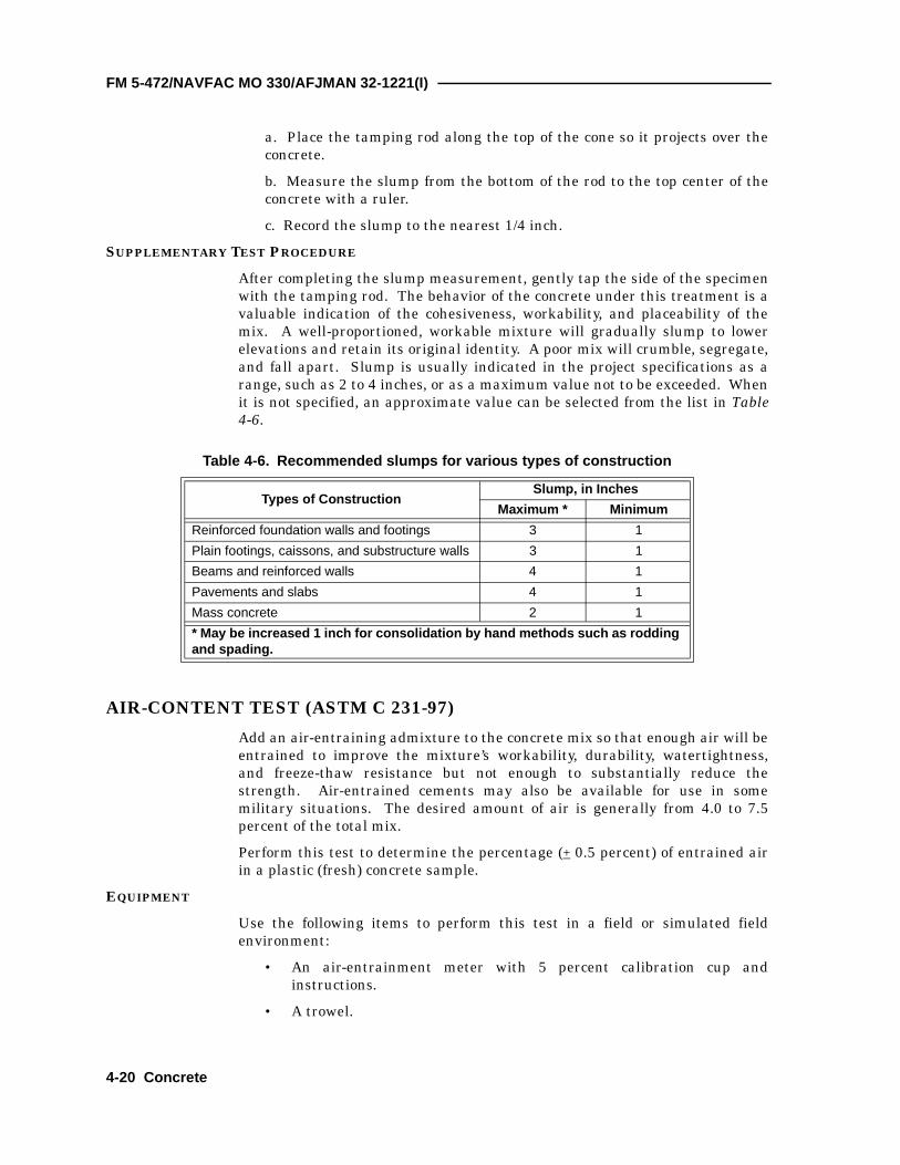
a. Place the tamping rod along the top of the cone so it projects over theconcrete.
b. Measure the slump from the bottom of the rod to the top center of theconcrete with a ruler.
c. Record the slump to the nearest 1/4 inch.
SUPPLEMENTARY TEST PROCEDURE
After completing the slump measurement, gently tap the side of the specimenwith the tamping rod. The behavior of the concrete under this treatment is avaluable indication of the cohesiveness, workability, and placeability of themix. A well-proportioned, workable mixture will gradually slump to lowerelevations and retain its original identity. A poor mix will crumble, segregate,and fall apart. Slump is usually indicated in the project specifications as arange, such as 2 to 4 inches, or as a maximum value not to be exceeded. Whenit is not specified, an approximate value can be selected from the list in Table4-6.
AIR-CONTENT TEST (ASTM C 231-97)
Add an air-entraining admixture to the concrete mix so that enough air will beentrained to improve the mixture’s workability, durability, watertightness,and freeze-thaw resistance but not enough to substantially reduce thestrength. Air-entrained cements may also be available for use in somemilitary situations. The desired amount of air is generally from 4.0 to 7.5percent of the total mix.
Perform this test to determine the percentage (+ 0.5 percent) of entrained airin a plastic (fresh) concrete sample.
EQUIPMENT
Use the following items to perform this test in a field or simulated fieldenvironment:
• An air-entrainment meter with 5 percent calibration cup andinstructions.
• A trowel.
Table 4-6. Recommended slumps for various types of construction
Types of ConstructionSlump, in Inches
Maximum * Minimum
Reinforced foundation walls and footings 3 1
Plain footings, caissons, and substructure walls 3 1
Beams and reinforced walls 4 1
Pavements and slabs 4 1
Mass concrete 2 1
* May be increased 1 inch for consolidation by hand methods such as rodding and spading.
4-20 Concrete

C2, FM 5-472/NAVFAC MO 330/AFJMAN 32-1221(I)
• A tamping rod (5/8 inch in diameter and 24 inches long with a roundedend).
• A sample of plastic (fresh) concrete.
• Water.
• Oil.
• Rags.
• A pail.
• A mixing pan (from the concrete test set).
• A kitchen scoop.
• Paper.
• A pencil.
• A rubber mallet.
STEPS
There are many different air-entrainment meters currently fielded andreplacements of old equipment may not be the same. For this reason, it isrecommended that the steps outlined in the manufacturer’s user’s manual befollowed.
The flexural strength of hardened concrete is measured by using a simpleconcrete beam and third-point loading mechanism. The flexural strength isdetermined by calculating measured breaks of the beam and is expressed as amodulus of rupture in psi.
TEST BEAMS
Beam forms for casting test beams from fresh concrete are available in manysizes. The most commonly used size is 6 x 6 x 21 inches. Although equipmentfor obtaining sawed specimens may not be available, the test may beperformed on beams sawed from existing concrete structures for evaluationpurposes.
FORMING THE BEAMS (ASTM C 192-90A)
Assemble a standard 6- x 6- x 21-inch concrete-beam mold and lightly oil theinside. Fill the mold with two layers of concrete from the production batches,each about 3 inches deep. Consolidate each layer by rodding, using one strokeper 2 square inches (63 per layer), evenly distributed over the layer’s surface.Tap the sides lightly 10 to 15 times with a rubber mallet to close the voids leftby rodding. Lightly spade the concrete along the mold’s sides with a trowel tohelp remove surface voids. When rodding the second layer, penetrate the firstlayer about 1/2 inch. Strike off the top surface with a straightedge, and finishit with a wood or magnesium float.
SECTION IV. FLEXURAL-STRENGTH TEST (MODULUS OF RUPTURE)
Concrete 4-21

FM 5-472/NAVFAC MO 330/AFJMAN 32-1221(I)
TAKING THE SPECIMENS
Take test specimens at least once for each 100 cubic yards or fraction thereof,for each class of concrete placed in any one day, or as directed in the projectspecifications. Make at least three specimens for each test age and mixturedesign being evaluated in the lab. Additional specimens may be made forfuture testing. Test ages are normally 14 and 28 days for flexural-strengthtests. For testing field-placed concrete, a minimum of two specimens for eachtest age is required.
CURING THE BEAMS
Place a suitable identifying label on the finished surface of the specimens.Cover the entire specimens—still in the mold—with a double thickness of wetburlap. Ensure that the specimens remain on site and are undisturbed for aninitial curing period (the first 16 to 48 hours after molding). After this curingperiod, move them to the testing laboratory and remove them from the moldsfor further curing. The most satisfactory curing range for concrete is 68° to86°F, with 73.4°F being the most favorable temperature. Moist-cure thebeams in saturated lime water, totally submerged in a wet-tank humidityroom, or keep them wet until they are tested.
FLEXURAL-STRENGTH TEST (ASTM C 78-94)
Perform this test to determine the flexural strength (modulus of rupture) ofthe test specimen to + 10 psi. Record the specimen identification, modulus ofrupture, any defects noted, and specimen’s age.
EQUIPMENT
Use the following items to perform this test in a laboratory environment:
• The flexural-strength test apparatus.
• A concrete beam, 6 x 6 x 21 inches.
• A measuring tape.
• A stopwatch.
• Pens.
• Pencils.
• Paper.
• Safety goggles.
• A proving-ring with proving-ring calibration and constant.
• Specimen identification.
• A calculator.
STEPS
Perform the following steps to determine the flexural strength. Wear safetygoggles throughout this test.
Step 1. Assemble the test apparatus and check for functional operation (seeFigure 4-5).
4-22 Concrete

C2, FM 5-472/NAVFAC MO 330/AFJMAN 32-1221(I)
Step 2. Measure the length of span and record the measurement on a piece ofpaper. The length of span is determined by measuring the distance fromcenter to center of the two loading points (or supports) on the base of theapparatus (see Figure 4-5). The normal length of specimen is 21 inches andthe normal length of span is 18 inches.
Step 3. Place the specimen in the tester and bring the loading surface intocontact with the test specimen (see Figure 4-5).
Step 4. Zero the gauge. Some apparatus are equipped with a hydraulic pumpand corresponding gauge while others are equipped with a loading jack andproving ring.
Step 5. Apply a load at a continuous rate that constantly increases theextreme fiber stress between 125 and 175 psi per minute. This is anapproximate load of 1,500 to 2,100 pounds per minute.
Step 6. Obtain the total load, in pounds, at the time of specimen failure, andrecord the weight on the paper provided. On machines equipped withhydraulics, take the reading directly from the gauge. For machines equippedwith a proving ring, this reading is the product of the dial-gauge reading andthe proving-ring constant.
Step 7. Determine and record the width and depth of the specimen, in inches,at the point of failure (normally 6 x 6 inches).
Step 8. Determine the point of failure in the specimen, and calculate themodulus of rupture. If the specimen fails outside the middle third of the spanlength by more than 5 percent of the total span length, then the specimen is
Figure 4-5. Apparatus for flexural-strength test
Steel rod
Specimen
Apply load here
Loading
Steel ball
Steel ball
Steel rod
Length of span
(d)in
Concrete 4-23

C2, FM 5-472/NAVFAC MO 330/AFJMAN 32-1221(I)
considered unusable and should be discarded (not more than 0.9 inches for an18-inch span (18 x 0.05 = 0.9).
a. Use the following formula to calculate the modulus of rupture if thespecimen fails within the middle third of the span length:
where—
R = modulus of rupture, in psi
P = applied load, in pounds
L = length of span, in inches
b = width of specimen at failure point, in inches
d = depth of specimen at failure point, in inches
b. Use the following formula to calculate the modulus of rupture if thespecimen fails outside the middle third of the length of span by not morethan 5 percent of the span length:
where—
R = modulus of rupture, in psi
P = applied load, in pounds
b = width of specimen at failure point, in inches
d = depth of specimen at failure point, in inches
a = distance between the failure point and the nearest support, measuredalong the centerline of the bottom of the specimen, in inches
Step 9. Record the following information about the test (some informationmay be unavailable at the time of the test):
• Specimen’s identification number.
• Average width to the nearest 0.05 inch.
• Average depth to the nearest 0.05 inch.
• Span length, in inches.
• Maximum applied load, in pounds.
• Modulus of rupture, to the nearest 10 psi.
• Curing history (how the specimen was cured) and apparent moisturecontent of the specimen at the time of the test.
• Any defects noted in the specimen.
• The age of the specimen.
RP L×b d2×---------------=
R3P a×b d2×----------------=
4-24 Concrete

FM 5-472/NAVFAC MO 330/AFJMAN 32-1221(I)
The compressive strength of hardened concrete, as measured by compressiontests on standard forms of cylindrical specimens, is used in the design ofstructures. Compressive-strength tests are made on concrete trial mixtures toevaluate the performance of available materials and to establish mixtureproportions that give the required strength. Strength tests are used also tocontrol the quality of concrete being manufactured in the field. Compressivestrength is defined as the average of the strengths of all cylinders of the sameage made from a sample taken from a single batch of concrete. At least twocylinders are required to constitute a test. Therefore, a minimum of fourspecimens are required if tests are to be made at 7 and 28 days. The testresults will be the average of the strengths of the two specimens tested at 28days.
CASTING A CONCRETE CYLINDER
The standard test specimen is a cylinder 6 inches in diameter by 12 incheslong, capped with a suitable material to provide smooth, bearing surfaces oneach end. Load is applied to the end surfaces through metal platens on thetesting machine (cylinder breaker), causing compressive stress in thelongitudinal direction of the cylinder.
Make the cylinders as near as possible to the place where they will be storedfor the first 16 to 48 hours. Sufficient concrete (about 1 cubic foot) for thedesired number of cylinders must be available in the trial mixture or fieldsample. Material from the air-content test must not be reused, since this maybe contaminated with excess water. Use appropriate sampling procedures forprocuring your sample as stated in Section III.
EQUIPMENT
Use the following items and information to perform this test in a field orsimulated field environment:
• A tamping rod (5/8 inch in diameter and 24 inches long with a roundedend).
• A sample of fresh concrete.
• A trowel.
• Oil.
• Rags.
• A disassembled cylinder mold.
• A sheet of plastic or burlap.
• A kitchen scoop.
• A pan (24 inches wide x 24 inches long x 3 inches deep).
• A grease pencil.
SECTION V. COMPRESSIVE-STRENGTH TEST
Concrete 4-25
FM 5-472/NAVFAC MO 330/AFJMAN 32-1221(I)
• Waterproof paper tags.
• Gummed labels.
• An ink pen.
• Paper.
• Water.
• The test-specimen number.
• The origin of a concrete sample.
STEPS
Perform the following steps to produce and label a concrete cylinder fortesting:
Step 1. Prepare the mold.
a. Clean and dry the mold.
b. Oil the mold lightly.
c. Assemble the mold.
Step 2. Make the cylinder.
a. Fill the mold one-third full with fresh concrete.
b. Consolidate the concrete by applying 25 evenly distributed strokes overthe mold’s surface area with the tamping rod. The tamping rod musttotally penetrate the layer of concrete.
c. Tap the side of the mold 8 to 10 times with the tamping rod.
d. Add concrete to the mold so as to fill it two-thirds full.
e. Apply 25 evenly distributed strokes to the mold’s surface area using therounded end of the tamping rod, which must pass entirely through thesecond layer of concrete and 1 inch into the preceding layer.
f. Tap the side of the mold 8 to 10 times with the tamping rod.
g. Add concrete to the mold to slightly overfill it.
h. Repeat step 2e. The tamping rod must pass entirely through the toplayer and 1 inch into the preceding layer.
i. Tap the side of the mold 8 to 10 times with the tamping rod.
j. Trowel off the concrete so that it is flush with the top of the mold andsmoothly finished.
Step 3. Label the mold. The label should include, as a minimum, all of thefollowing information:
• The specimen number.
• The date the cylinder was made.
• The project or placement that the concrete came from.
4-26 Concrete

FM 5-472/NAVFAC MO 330/AFJMAN 32-1221(I)
The system of labeling is optional. The information should be recorded on apaper tag or gummed label and attached to the mold.
Step 4. Cover the cylinder with plastic or wet burlap to maintain moisture inthe sample. The covering should be tight around the cylinder but should notmake contact with the fresh concrete.
Step 5. Allow the cylinder to cure undisturbed for 24 hours.
Step 6. Remove the covering and the mold from the cylinder after 24 (+ 8)hours.
Step 7. Transfer the label from the mold to the concrete cylinder. The labelitself may be transferred or the information may be recorded directly on thecylinder with a grease pencil.
Step 8. Cure the cylinder.
NUMBER OF SPECIMENS
The number of specimens tested depends on the job specifications. If norequirement is listed in the specifications, a minimum of 2 will be molded foreach test age for each 100 cubic yards, or fraction thereof, of each class ofconcrete placed in any one day. A third specimen may be taken to assist indetermining when forms may be removed. The test specimens must remainon site and undisturbed for an initial curing period (the first 16 to 48 hoursafter molding). Normally the test ages are 7 and 28 days for compressivestrength tests.
CURING AND STORING CYLINDERS
After an initial curing period for 16 to 48 hours, remove (from the jobsite)specimens that are intended for checking the strength of laboratory trialmixtures or to serve as the basis for acceptance or quality control of fieldconcrete. Take them to the testing laboratory and moist-cure them at 73.4°F.Store them in moist rooms, in damp sand or sawdust, or in limewater tomaintain free water on all surfaces of the specimen at all times.
Occasionally, test specimens are made in the field to determine when formsmay be removed. Form these in addition to the specimens formed for strengthdetermination. Give these specimens (as much as possible) the sameprotection from the elements on all surfaces as is given to the portions of thestructure that they represent. Store them in or on the structure as near aspossible to the point of use. Test them in the moist condition resulting fromthe specified curing treatment. Specimens intended for testing to determinewhen a structure may be put into use are removed from the molds at the sametime the forms are removed from the structure.
When shipping specimens from the field to the laboratory for testing, packthem in a sturdy wooden box or other suitable container surrounded by wetsawdust or wet sand. Provide protection from freezing during storage orshipment. Moist curing is continued when the specimens are received in thelaboratory.
Concrete 4-27

FM 5-472/NAVFAC MO 330/AFJMAN 32-1221(I)
CAPPING CYLINDERS
Plane the ends of compression-test specimens within 0.002 inch and within0.5 degree of being perpendicular to the axis of the cylinder.
Cap (with neat cement) specimens formed in strong metal molds havingaccurately flat baseplates 2 to 4 hours after molding. Make a stiff paste ofportland cement and water at the time the cylinder is molded so that thecapping mixture will shrink before application. Remove any free water orlaitance a (layer of fine particles on the surface) from the end of thespecimen. Apply the paste to the top of the concrete and work it with a flatplate until it is smooth and level with the top of the mold.
Grind hardened concrete specimens to smooth the ends or cap them with amaterial having greater compressive strength than the concrete. Preparedmixtures of sulfur and granular materials, special high-strength gypsumplasters, and neat high-early strength cement are satisfactory cappingmaterials (ordinary low-strength plaster of paris, compressible rubber, orfibrous materials are not suitable for caps). Apply the selected material in aplastic state and finish it to the desired plane surface by applying glass ormetal plates and squeezing out excess material to provide a cap that is asthin as possible.
Apply sulfur caps in time to harden at least 2 hours before testing. Plastercaps cannot be stored over 4 hours in the moist room. Age neat cement caps6 days or more in the moist room (2 days when Type II cement is used).During capping, protect moist-cured specimens against drying by coveringthem with wet burlap. There are numerous alternatives to sulfur caps listedin ASTM C 617-94. The metal cap with a rubber membrane is not an ASTM-approved method; however, specific guidelines for their use are under reviewby the ASTM. The test procedures used in this manual refer to the metalcaps due to their availability within the supply system. If you must usesulfur caps, ensure that sulfur vapors are not inhaled while heating thecapping compound. Ensure that there is adequate ventilation and thatrespiratory protection is used. Used sulfur capping compound is ahazardous material and must be properly disposed of.
DETERMINING COMPRESSIVE STRENGTH OF A CYLINDRICAL SPECIMEN (ASTM C 39-96)
Perform this test to determine the compressive strength of the concretecylinder to within breakage and to determine anything unusual about thebreak.
EQUIPMENT
Use the following items to perform this test in a well-ventilated laboratory:
• A concrete cylinder (6 inches in diameter and 12 inches in height).
• A concrete capping set.
• Heat-resistant gloves.
• Capping compound.
4-28 Concrete

FM 5-472/NAVFAC MO 330/AFJMAN 32-1221(I)
• A ruler accurate to 0.01 inch.
• Calipers with at least a 6-inch opening.
• Paper.
• Pencils.
• Safety goggles and protective apron.
• A face shield.
• Oil.
• Rags.
• A calculator.
• A concrete compression tester with a 250,000-pound capacity.
• A hammer (ball peen or carpenter’s).
STEPS
Perform the following steps to determine the concrete cylinder’s compressivestrength:
Step 1. Prepare the concrete cylinder.
NOTE: If rubber-filled metal is used, go to step 1j.
a. Melt the capping compound in the melting pot. Ensure that you meltenough compound to make several caps.
b. Clean and lightly oil the baseplate of the capping apparatus.
c. Set the baseplate into the capping-apparatus stand.
d. Pour a small amount of the heated (liquid) capping compound into thebaseplate.
e. Position the cylinder at midheight against the backrest of the cappingapparatus. Slowly lower the cylinder into the baseplate while keeping thecylinder flush against the backrest. If the cylinder is not kept flush withthe backrest while capping, the caps and the cylinder will not beperpendicular, and a proper break will not occur.
f. Remove the cylinder from the capping apparatus once the cappingcompound has solidified.
g. Inspect the cap for uniformity and defects. If you see any defects,remove the cap and recap the cylinder; then return to step 1a.
h. Repeat steps 1a through 1g for the uncapped end of the cylinder.
i. Determine and record the average diameter of the concrete cylinder.The average diameter is the average of two diameters taken perpendicularto each other at midheight of the cylinder.
j. Clean and examine the bearing surface of the steel cap (if used) fornicks, gouges, and warping. Check the rubber inserts for tears, rips, cuts,and gouges. Replace them if they are in poor condition or if the maximum
Concrete 4-29

C2, FM 5-472/NAVFAC MO 330/AFJMAN 32-1221(I)
number of serviceable uses has been exceeded. Place the steel cap firmlyon the cylinder’s ends.
Step 2. Prepare the compression tester (see Figure 4-6).
a. Clean the tester’s bearing plates (loading surfaces).
b. Check the tester for proper operation.
c. Set the gauge to zero.
Step 3. Place the capped cylinder into the compression tester and center it onthe bearing plates. Secure the protective cage around the cylinder.
Step 4. Apply the test load at a rate of 20 to 50 psi per second, not to exceed 50psi per second (50 psi per second is about equivalent to a load [gauge reading]of 1,400 pounds per second).
Step 5. Read the gauge and record the load applied at the time of failure.
Step 6. Inspect the broken cylinder and record the following information:
• Identification number.
• Diameter.
• Cross-sectional area, in square inches.
• Maximum load applied, in pounds.
• Compressive strength, calculated to the nearest 10 psi.
• Type of break (see Figure 4-7).
• Defects in either specimen or caps.
• Age of specimen.
Step 7. Calculate and record the compressive strength of the cylinder usingthe following formula:
where—
P = load at time of failure, in pounds
A = π r2
Compressive strengthPA---=
4-30 Concrete

Concrete 4-31
C2, FM 5-472/NAVFAC MO 330/AFJMAN 32-1221(I)
Figure 4-6. Compression tester
Figure 4-7. Types of fractures
Cone Cone and split Cone and shear Shear Columnar