chapter 4 – concrete/steel section - ct.gov … 4 – concrete/steel section overview the...
TRANSCRIPT
Chapter 4 – Concrete/Steel Section Overview The Concrete/Steel Section performs testing and/or inspection of portland cement concrete and related materials, structural steel and incidental construction and maintenance materials used by the Department. The section is composed of the following subsections: Concrete/Physical Testing, Cement/Aggregate/Portland Cement, Concrete Plant/Field Operations and Structural Steel Fabrication. The Supervising Materials Testing Engineer (SMTE) is the administrative and technical head of the Concrete/Steel Section and reports directly to the Director of Research and Materials. The SMTE directs the testing of all concrete, concrete products and allied products; directs the sampling and testing of metals. The SMTE also administers the inspection activities of a commercial testing agency under contract to the ConnDOT for the purpose of shop inspection of the fabrication of structural steel and precast/prestressed concrete structures. The SMTE makes recommendations as to the solution of problems concerning portland cement concrete, its production and use, and the fabrication of precast/prestressed concrete structures and structural steel; conducts research into the development of improved concrete mixes, concrete products and other construction materials; initiates and directs the training of laboratory and construction personnel in the sampling and testing of materials, to include training in the nondestructive testing of welds; reviews work activities of all employees to ensure technical competence in job performance and satisfactory attendance; prepares and keeps current the concrete/steel section of the DMT's “Materials Testing Manual;” initiates and aids in the preparation of material specifications; confers with producers, contractors and engineers concerning materials and their uses; initiates or supervises the preparation of technical reports or allied documents; directs the application of statistical techniques to the quality control of materials; prepares personnel, equipment and overtime budget requirements; directs the maintenance, calibration and procurement of equipment and apparatus necessary for testing and inspection purposes. The SMTE is also responsible for the daily activities of Department personnel dedicated to the quality assurance of structural-steel and related materials for Department projects. The SMTE assigns, oversees, and evaluates these personnel. Further duties of the SMTE include making recommendations as to the suitability for use of construction and maintenance materials used by the Department such as cement, concrete, aggregates, Portland cement concrete mixtures, precast and/or prestressed concrete products, structural steel products, pipe, guiderail, signs, traffic signals, highway illumination items, etc. A Materials Testing Engineer (MTE)/Trans. Engineer III (TE3) assists the SMTE. The MTE/TE3 is responsible for the routine operation of the Concrete and Physical Test Unit, monitors the job performance of field personnel by periodic visits to the work sites and assesses an employee's technical competence and conformance to standard testing techniques. In the absence of the SMTE, the MTE/TE3 is the acting head of the entire Section. Each of the functional subsections within the Section is headed by a Materials Technician III (MT3) or Trans. Engineer II (TE2) who directs the testing and inspection operations applicable to that subsection. The MT3 or TE2 supervises employees who are assigned to that subsection; schedules personnel for duty assignments; reviews work, both in progress and after completion, to ensure competent job performance by the employee; and monitors employee attendance and conformance to the daily work schedule.
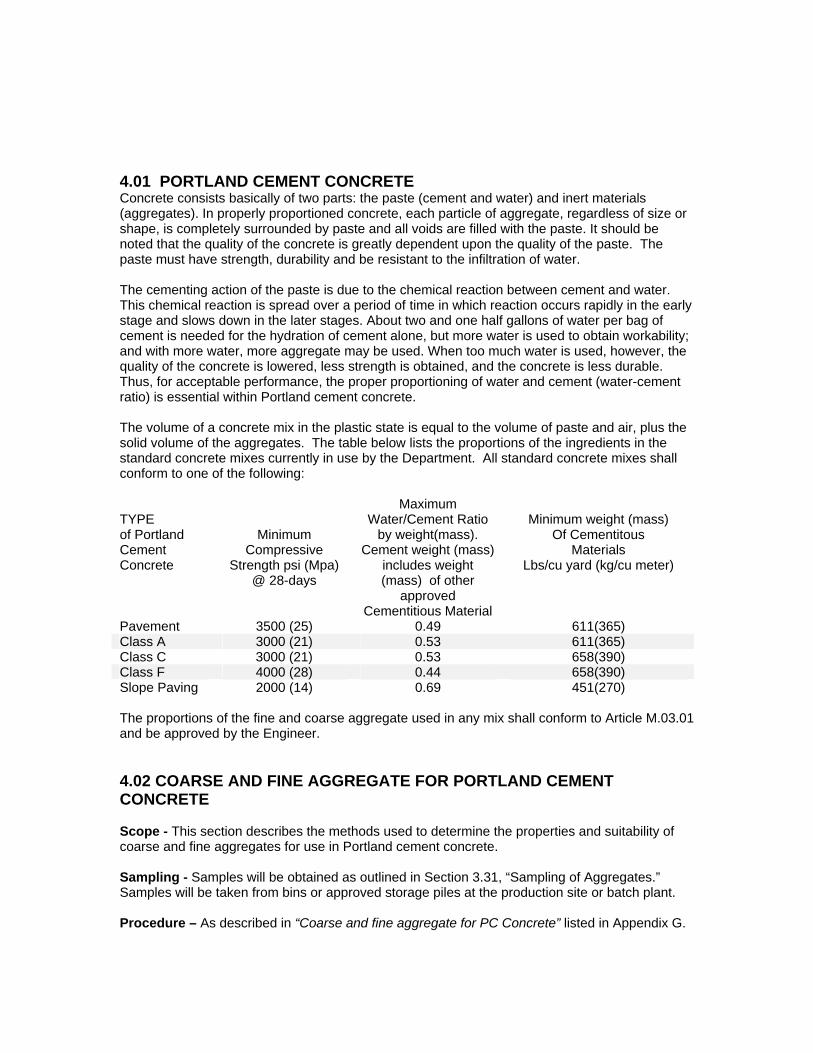
4.01 PORTLAND CEMENT CONCRETE Concrete consists basically of two parts: the paste (cement and water) and inert materials (aggregates). In properly proportioned concrete, each particle of aggregate, regardless of size or shape, is completely surrounded by paste and all voids are filled with the paste. It should be noted that the quality of the concrete is greatly dependent upon the quality of the paste. The paste must have strength, durability and be resistant to the infiltration of water. The cementing action of the paste is due to the chemical reaction between cement and water. This chemical reaction is spread over a period of time in which reaction occurs rapidly in the early stage and slows down in the later stages. About two and one half gallons of water per bag of cement is needed for the hydration of cement alone, but more water is used to obtain workability; and with more water, more aggregate may be used. When too much water is used, however, the quality of the concrete is lowered, less strength is obtained, and the concrete is less durable. Thus, for acceptable performance, the proper proportioning of water and cement (water-cement ratio) is essential within Portland cement concrete. The volume of a concrete mix in the plastic state is equal to the volume of paste and air, plus the solid volume of the aggregates. The table below lists the proportions of the ingredients in the standard concrete mixes currently in use by the Department. All standard concrete mixes shall conform to one of the following: TYPE of Portland Cement Concrete
Minimum Compressive
Strength psi (Mpa) @ 28-days
Maximum Water/Cement Ratio
by weight(mass). Cement weight (mass)
includes weight (mass) of other
approved Cementitious Material
Minimum weight (mass)
Of Cementitous Materials
Lbs/cu yard (kg/cu meter)
Pavement 3500 (25) 0.49 611(365) Class A 3000 (21) 0.53 611(365) Class C 3000 (21) 0.53 658(390) Class F 4000 (28) 0.44 658(390) Slope Paving 2000 (14) 0.69 451(270) The proportions of the fine and coarse aggregate used in any mix shall conform to Article M.03.01 and be approved by the Engineer. 4.02 COARSE AND FINE AGGREGATE FOR PORTLAND CEMENT CONCRETE Scope - This section describes the methods used to determine the properties and suitability of coarse and fine aggregates for use in Portland cement concrete. Sampling - Samples will be obtained as outlined in Section 3.31, “Sampling of Aggregates.” Samples will be taken from bins or approved storage piles at the production site or batch plant. Procedure – As described in “Coarse and fine aggregate for PC Concrete” listed in Appendix G.
Specification - Standard Specifications, Article M.03.01
Report - Forms MAT-205, MAT-206 or MAT-207. 4.03 PORTLAND CEMENT Scope – This section covers the requirements for testing Portland cement to be used in the production of concrete for use in Department projects. Sampling - All Portland cement delivered to a construction site will be sampled by a representative of the Department and submitted with a MAT-100 to the DMT. An acceptable sample is a single factory sealed bag of each type used on the project. Sampling at a terminal or bulk storage facility will be done by DMT personnel to asssure the quality of Portland Cement used in concrete delivered to a project in accordance with the ConnDOT Program for Acceptance of Cement by Certification. Procedure - Test procedures will be as prescribed by AASHTO M 85 or M 240, whichever is applicable. Specification - In accordance with AASHTO M 85 or AASHTO M 240 Report - Form MAT-316, 317, 318, 319, or 320 whichever applies. 4.04 TRANSVERSE JOINTS FOR CONCRETE PAVEMENT Scope - This section covers corrosion-resistant load transfer devices, preformed expansion joint fillers,and wood joint filler. LOAD TRANSFER DEVICES Sampling – Project personnel are responsible for submitting a MAT-100 with a minimum of two (2) samples, accompanied by a Certified Test Report conforming to the requirements of Standard Specifications, Article 1.06.07, for each shipment. Note: Each sample must consist of at least three (3) load transfer dowels. Procedure – DMT personnel will review the Certified Test Report to ensure conformance to specification. When required, assurance Tests will be performed in accordance with AASHTO T 253 and AASHTO T 244. Specification - Standard Specifications, Article M.03.01-5 Report - Forms MAT-315. PREFORMED EXPANSION JOINT FILLERS Sampling – Project personnel are responsible for submitting a MAT-100 with a Materials Certificate and Certified Test Report conforming to Standard Specifications, Article 1.06.07, for
each shipment. Samples for assurance testing when required must consist of one (1) square foot per size per shipment. Procedure – DMT personnel will review the Certified Test Report to ensure conformance to specification. When required, assurance tests will be performed in accordance with AASHTO T 42 Specification - Standard Specifications, Article M.03.01-5 Report - Forms MAT-315 WOOD JOINT FILLER Sampling – Project personnel are responsible for submitting a MAT-100 with a Materials Certificate conforming to Standard Specifications, Article 1.06.07, for each shipment. Note: Materials Certificate must include a statement indicating preservative treatment. Procedure – DMT personnel will review the Certified Test Report to ensure conformance to specification. Specification - Standard Specifications, Article M.03.01-5 Report - Forms MAT-315 4.05 LONGITUDINAL JOINT DEVICES Scope - This section covers longitudinal joint devices for use in the construction of concrete pavements. Sampling – Project personnel are responsible for submitting a MAT-100 with a Materials Certificate for each shipment. When required for assurance testing, one sample (six units) will be submitted for each mile (1.6 km) of pavement. Procedure - DMT personnel will review the Certified Test Report to ensure conformance to specification. When required, assurance testing will be conducted in accordance with AASHTO T 244 Specification - In accordance with Standard Specifications, Article M.03.01-6. The dimensions will be as shown on the plans Report - Form MAT-315 4.06 PREFORMED EXPANSION JOINT FOR STRUCTURES Scope - This section covers expansion joint material to be used in the construction of concrete structures. Sampling – Project personnel are responsible for submitting a minimum of one sample with a MAT-100 for each shipment. An acceptable sample is a square with a minimum dimension of 12-in on any side. Procedure
1. Preformed expansion joint filler for bridges: In accordance with AASHTO T 42, Type II. 2. Premolded expansion joint filler for bridge bearings: In accordance with AASHTO T 42.
Specification
1. Preformed expansion joint filler for bridges: In accordance with AASHTO M 153, Type II. 2. Premolded expansion joint filler for bridge bearings: In accordance with AASHTO M 33.
Report - Form MAT-315. 4.07 JOINT SEALANTS Scope - This section covers joint sealants for use in concrete pavement and concrete structures. Sampling - In accordance with AASHTO M 173 Procedure - In accordance with AASHTO T 187 Specification - In accordance with AASHTO M 173 Report - Form MAT-424 or 425.
Structures Sampling - N/A Procedure - Joint sealants for structures will be as specified on the plans or as required by the Special Provisions. Specification - As specified on the plans or in the Special Provisions Report - Form MAT-424 or 425. 4.08 ADMIXTURES Scope When project specifications require that an admixture shall perform the desired function without injurious effect upon the concrete, proof of conformance to this requirement will be in the form of a certified statement from a recognized laboratory. The certified statement will contain evidence based on tests pertinent to the admixture made in the recognized laboratory by the use of concrete materials and by methods that meet requirements of current AASHTO and ASTM standards. Tests may be made on samples taken from a quantity submitted by the Contractor for use on the project or on samples submitted and certified by the manufacturer as representative of the admixture to be supplied. A recognized laboratory is any cement and concrete laboratory approved by the Engineer and inspected regularly by the Cement and Concrete Reference Laboratory sponsored by ASTM and the National Institute of Standards and Technology. Sampling - In accordance with AASHTO M 154 and AASHTO M 194 Procedure - Approval of the certified statement submitted for an admixture will qualify that admixture for inclusion in the Department Qualified Products List regarding Admixtures for Portland Cement Concrete. Specification - In accordance with Standard Specifications, Article M.03.01-9
Report – MAT-315 4.09 PROTECTIVE COMPOUND MATERIAL Scope - This section covers material used as a protective coating for surfaces of concrete structures. Sampling - Samples are not required on a project level. Qualified products are listed on the Departments “Qualified Products List”. Procedure - Standard Specifications, Article M.03.01-11 Specification - Standard Specifications, Article M.03.01-11 Report - Form MAT-315. 4.10 NON-SHRINK, NON-STAINING GROUT Scope - This section covers non-shrink, nonstaining grout for use as directed in the plans or specifications. Sampling – Project personnel are responsible for submitting one (1) unopened container of the premixed material with a MAT-100 per shipment per project. Container will be clearly marked with the manufacturers name, date of production, batch number, and instructions for proper mixing, placement, and curing of the material. Procedure - Non-shrink, nonstaining grout will be tested in accordance with ASTM C 1107, Grade B. Specification - Standard Specifications, Article M.03.01-12 Report - Form MAT-330 4.11 MAKING AND CURING CONCRETE TEST SPECIMENS IN THE LABORATORY Scope - This section covers procedures for making and curing test specimens of concrete in the laboratory under accurate control of materials and test conditions in order to determine variations in the properties of the plastic and hardened concrete. Sampling - In accordance with the Standard Method for Sampling Freshly Mixed Concrete, AASHTO T 141. Procedure - The procedure for preparing the concrete and the procedures for molding and curing the test specimens will be in accordance with the Standard Method of Making and Curing Concrete Test Specimens in the Laboratory, AASHTO T 126. 4.12 CONCRETE CORES
Scope - This section covers the procedure for obtaining, preparing and testing specimens of hardened concrete from structures and pavements. Sampling - In accordance with the Standard Method for Obtaining and Testing Drilled Cores and Sawed Beams of Concrete, AASHTO T 24. Procedure - In accordance with the Standard Method for Obtaining and Testing Drilled Cores and Sawed Beams of Concrete, AASHTO T 24. Specification - In accordance with Standard Specifications, Section 4.01 or 6.01 whichever applies. Report - Form MAT-321 4.13 CONCRETE CORES (LENGTH) Scope - This section covers the procedure for determining the length of a core drilled from a concrete pavement or structure. Sampling - In accordance with the Standard Method of Measuring the Length of Drilled Concrete Cores, AASHTO T 148, Section 4 – Test Specimens. Procedure - In accordance with the Standard Method of Measuring the Length of Drilled Concrete Cores, AASHTO T 148, Section 5 - Procedure. Specification - In accordance with Standard Specifications, Section 4.01 or 6.01 whichever applies. Report - Form MAT-409 4.14 COMPRESSIVE STRENGTH OF CYLINDRICAL CONCRETE SPECIMENS Scope - This section covers the procedure for compression testing of molded concrete cylinders. Sampling - In accordance with the Standard Method of Sampling Freshly Mixed Concrete, AASHTO T 141; the Standard Method of Making and Curing Concrete Test Specimens in the Lab, AASHTO T 126. Procedure - In accordance with the Standard Method for Compressive Strength of Cylindrical Concrete Specimens, AASHTO T 22. Specification - In accordance with Standard Specifications, Section 4.01 or 6.01 Report - Form MAT-308 4.15 STEEL REINFORCING BARS FOR CONCRETE Scope - This section covers deformed billet steel bars for concrete reinforcement.
Sampling - A sample of each size bar will be submitted for each shipment as follows: All sizes-one sample per size from each manufacturer for each 200 tons. Samples submitted for test will be cut from the shipment on the project site and will be not less than 5 ft. (1.5 m) in length. Procedure - In accordance with AASHTO T 244 Specification - Bar reinforcement will be tested in accordance with procedures prescribed in AASHTO M 31 (ASTM A 615) and shall conform to the requirements of Grades 60 or metric grade 420, whichever is required by the project specifications. Bar reinforcement required to be galvanized or epoxy coated shall be in accordance with ASTM A 153 for galvanized material, or AASHTO M 284 for epoxy coated material. Report - Form MAT-305 4.16 WIRE AND WELDED WIRE STEEL WIRE FABRIC Scope - This section covers wire and welded steel wire fabric for use as concrete reinforcement. Sampling – A 1 yd2 (0.9 m2) sample of each type will be submitted for test per 8,000 yd2 (7,000 m2 ) of fabric used. Procedure - In accordance with AASHTO T 244 Specification Specifications for the various types of wire and welded steel wire fabric shall be as follows:
1. Cold-drawn steel wire: AASHTO M 32 2. Welded steel wire fabric: AASHTO M 55 3. Deformed steel wire: AASHTO M 225 4. Welded Deformed Steel Wire Fabric: AASHTO M 221
Report - Form MAT-306 or 328 whichever applies. 4.17 DEFORMED BAR MAT REINFORCEMENT Scope - This section covers deformed bar mat reinforcement for use in the construction of concrete pavement. Sampling - One sample consisting of 1 yd2 (m2)of each type will be submitted for each 1 mile (1.6 km) of pavement lane. Procedure - In accordance with AASHTO T 244 Specification - In accordance with AASHTO M 54 Report - Form MAT-305 4.18 PRESTRESSING STEEL Scope - This section covers uncoated high tensile strength, seven-wire, steel strand for use in prestressed and post-tensioned concrete members.
Sampling - One 7 ft. (2.2 m) length and one 1 ft. (305 mm) length of strand shall be sampled for test from each reel or coil. Up to five reel packs or coils identified with the same heat number can be covered with a single sample. Procedure - In accordance with AASHTO T 244 Specification - In accordance with AASHTO M 203 Report - Form MAT-323
4.19 STRUCTURAL STEEL Scope - This section covers all structural steel for use in riveted, bolted or welded construction. STEEL Sampling - Test samples for the grade of structural steel specified on the plans or in the Special Provisions shall be in accordance with Standard Specifications, Article M.06.02-1 (Charpy V-notch) Procedure - As specified on the plans or in the Special Provisions and in accordance with Standard Specifications, Article M. 06.02. Project personnel are responsible for submitting a MAT-100 when the material is delivered to the project site. Specification - As specified on the plans or in the Special Provisions and in accordance with Standard Specifications, Article 6.03 and M.06.02. Report - Form MAT-305 or 315 whichever applies. STRUCTURAL STEEL COATINGS Sampling - Test samples of coatings are generally not required unless specified in the project Special Provisions or on the plans. All paint must be approved by the Northeast Protective Coating Committee (NEPCOAT) and listed on their Qualified Products List A or B. Procedure – Fabricators of structural steel are responsible for making themselves aware of the entire coating specification for each individual project prior to starting the work. The DMT must be notified in advance of any coating work on structural steel for Department use. Field painting and touch-up work must conform to Article 6.03.03-38. Project personnel are responsible for submitting a MAT-100 when the material is delivered to the project site. Specification - As specified on the plans, in the Special Provisions or in accordance with Standard Specifications, Article 6.03 and M.07. Report - Form MAT-315. 4.20 EYEBAR STEEL Scope - This section covers steel for eye bars. Sampling - Sampling will conform to those required for the grade of steel specified on the plans or in the contract documents.
Procedure - Procedures shall conform to those required for the grade of steel specified on the plans or in the contract documents. Specification - Specifications shall conform to those required for the grade of steel specified on the plans or in the contract documents. Report - Form MAT-315. 4.21 ANCHOR BOLTS Scope - This section covers anchor bolts, nuts and washers for structural steel construction. Sampling - One (1) bolt for each size, heat #, and shipment is required for each project. Each sample must be submitted with a Certified Test Report and Materials Certificate. Procedure - In accordance with AASHTO T 244 Specification - Standard Specs, M.06.02-2 and M.15.02-1, 2 and 3, and/or project special provisions. Report - Form MAT-300 or MAT-301 whichever applies. 4.22 HIGH STRENGTH BOLTS Scope - This section covers high strength bolts, nuts and washers for use in structural steel construction. Sampling - Submit request for test with sample, Certified Test Report, and Materials Certificate. Procedure - In accordance with ”Standard Method of Test for Mechanical Testing of Steel Products” AASHTO T 244. Certified Test Report and Materials Certificate must show conformance to applicable specifications. Specification - Standard Specifications, Articles M.06.02-5, and/or project special provisions. Report - Form MAT-302 4.23 STEEL SHAFTINGS AND FORGINGS Scope - This section covers pins and rollers for structural steel construction. Sampling - In accordance with Standard Specifications, Article M.06.02-7 Procedure - In accordance with Standard Specifications, Article M.06.02-7 Specialization - In accordance with Standard Specifications, Article M.06.02-7 Report - Form MAT-305 4.24 WELDED AND SEAMLESS STEEL PIPE Scope - This section covers welded and seamless steel pipe
Sampling - In accordance with ASTM A 53 and as supplemented in Standard Specifications, Article M.06.02-8. Procedure - In accordance with ASTM A 53 and as supplemented in Standard Specifications, Article M.06.02-8. Specification - In accordance with ASTM A 53 and as supplemented in Standard Specifications, Article M.06.02-8. Report - Form MAT-315 4.25 METAL CASTINGS Scope - This section covers castings for general application in highway and bridge construction. Refer to Standard Specifications, Article M.06.02-9 for general condition of casting. Sampling - In accordance with the governing specifications as indicated below. Procedure and Specification- In accordance with the following unless otherwise specified:
Carbon Steel Castings shall conform to ASTM A 27. Grade 415-205, 450-240, or 485-250 Malleable Castings shall conform to ASTM A 47, Grade 24018. Ductile Iron Castings shall conform to ASTM A 536, Grade 414-276-18. Gray Iron Castings shall conform to ASTM A 48 Class 207. Chromium Alloy Steel Castings shall conform to ASTM A 296 Grade 10.
Report - Form MAT-315
4.26 BRONZE OR COPPER ALLOY BEARING AND EXPANSION PLATES Scope - This section covers bronze or copper alloy bearing or expansion plates intended for use in bridge construction. Sampling - Standard Specifications, Article M.06.02-10 Procedure - The Contractor shall submit a Certified Test Report confirming that the lubricant compound conforms to Standard Specifications, Article M.06.02-10 and the project specification. Specification - Standard Specifications, Article M.06.02-10 Report - Laboratory test results will be reported on Form MAT-315 4.27 ALUMINUM CASTING, TUBING AND FITTINGS Scope - This section covers aluminum castings, tubing and fittings for ornamental posts, traffic rail posts, bases, post connection splice bars, end caps, etc. Sampling - Standard Specifications, M.06.02-11
Procedure - In accordance with Standard Specifications, M.06.02-11 Specification - Standard Specifications, M.06.02-11 Report - Form MAT-315. 4.28 MILL AND SHOP INSPECTION OF STRUCTURAL STEEL Scope - This section covers the mill and shop inspection of structural steel. Sampling - N/A Procedure - Mill and shop inspection shall be in accordance with Standard Specification, Article 6.03.03. Specification - Standard Specification Article 6.03.03.
Report - Reports will be submitted in accordance with the consultant inspection contracts and distributed by DMT personnel to the appropriate district construction personnel. 4.29 GALVANIZING Scope - This section covers galvanizing on iron and steel materials other than wire. Also, galvanized grates incorporated into catch basin tops are marked in the field by a Department inspector and are documented through the MAT-314 (PC-1) . Sampling - N/A Procedure - In accordance with ASTM A 123 or ASTM A 153, whichever shall apply. Specification - In accordance with ASTM A 123 or ASTM A 153, whichever shall apply. Report – Form MAT-315. 4.30 FILLER METAL FOR WELDING Scope - This section covers filler metal for welding in highway construction. Sampling - One sample of each size and lot of electrodes used for field welding shall be submitted for each project with certified test reports to the DMT. Procedure - In accordance with Standard Specifications, Article M.06.04. Specification - In accordance with Standard Specifications, Article M.06.04. Report - Form MAT-315. 4.31 CERTIFICATION OF WELDERS
Scope - This section covers the certification of field welders who perform work on Department projects. Sampling – All welders working on Department projects must be certified by the DMT and must posses a valid up-to-date certificate for the duration of any welding operations. Procedure - In accordance with Standard Specifications, Article 6.03.03-6. Specification - In accordance with Standard Specifications, Article 6.03.03-6. Report - Welders who pass certification testing will be issued a ConnDOT Welder Certification I.D. card by DMT personnel. The ID card is valid for two years from date of issue and must be updated every six months. The ID card contains qualified weld processes and positions informaton. 4.32 REINFORCED CONCRETE PIPE AND ALLIED PRODUCTS Purpose
This outline is to serve as a guide to personnel involved in the inspection of the manufacture of reinforced concrete pipe and allied products. Many factors enter into the proper control of reinforced concrete pipe manufacturing. It is a combination of good quality control and quality assurance.
1. Testing and inspection of the various materials selected for use. 2. Proper proportioning and adequate mixing of the materials. 3. Sufficient reinforcement and proper placement of reinforcement within form work. 4. Proper handling, placing and consolidating procedures. 5. Proper curing of the product.
To ensure effective inspection, each phase should be carefully observed. A competent inspector should become familiar with various. manufacturing processes, designs, specifications, and procedures followed for the particular plant at which they are inspecting.
Scope This section covers reinforced concrete pipe and allied products, (reinforced elliptical concrete pipe, slotted reinforced concrete pipe, and reinforced concrete culvert ends for underdrains and outlets) that may be accepted by the Department on the basis of the manufacturer's certification. Products covered under this item shall include, but not be limited to, reinforced concrete pipe intended for use by the Department in the construction of culverts, slotted reinforced concrete pipe for use as underdrains, and reinforced concrete culvert ends. Annual Plant Inspection
The purpose of this inspection is to ensure that a plant is capable of producing a product in accordance with those standards set forth in AASHTO M 170M, AASHTO M 207M and AASHTO M 175M Type II, amended and supplemented by Standard Specifications, Article M.08.01 as applicable.
Inspection Form MAT-324 indicates the name, address and plant number of the manufacturer and list the number, make, capacity, type and condition of all scales and seal dates, mixers and pipe machines intended for use on ConnDOT projects.
Materials
The inspector will obtain samples of cement, water, coarse aggregate, fine aggregate, admixtures and reinforcing steel he proposed for use on the project from the manufacturer and indicate on Form MAT-324 the suppliers of the materials.
Sampling
Component materials will be sampled as follows:
1. Portland cement shall conform to AASHTO M 85. All cement will be sampled at the mill and tested by an approved laboratory whose methods and equipment are regularly inspected by the Cement and Concrete Reference Laboratory. One copy of the test report certifying the acceptability of the cement shall be furnished to the Director of Research and Materials. At the time of the annual inspection, the inspector may obtain a sample of cement currently in use and a copy of the corresponding certified test report. Cement shall be subject to sampling and testing at any time by the Department.
2. Aggregate: Aggregate Samples shall be obtained from approved storage piles or bins by the inspector during the annual inspection. Additional aggregate samples shall be taken at least once every month or from each new source.
3. Water: Each source of supply shall be sampled annually. 4. Reinforcement: Samples of each size and type of reinforcement shall be taken every six
months, or as required. 5. Admixtures: Only approved admixtures shall be used. Samples of each type of
admixture from each source of supply shall be obtained annually or as required.
Fabrication
Fabrication of reinforced concrete pipe shall be in accordance with AASHTO M 170M; AASHTO M 207M; and Standard Specifications, Articles M.08.01-6, 9, 10 and 22, as applicable.
The inspector will observe the production process which shall include checking the splices, spacing and size of reinforcing at the time cages are assembled. The reinforcing shall be lapped not less than 51 mm and welded with an electric welding machine. The spacing, center-to-center, of adjacent rings of circumferential reinforcement in the cage shall not exceed 102 mm for pipe having a 102 mm wall thickness, nor exceed the wall thickness for larger pipe, and in no case shall exceed 152 mm. The cage shall contain sufficient longitudinal bars or members, extending through the wall of the pipe to maintain the reinforcement rigidly in shape and in the correct position within the form. For multiple layers, a line of circumferential reinforcement for any given total area may be composed of two layers for pipe with a wall thickness of less than 178 mm or three layers for pipe with a wall thickness of 178 mm or greater. The layers shall not be separated by more than the thickness of one longitudinal plus 6.4 mm. The multiple layers shall be fastened together to forma single rigid cage. All other specification requirements such as laps, welds, tolerance of placement in the wall of the pipe, etc., shall apply to this method of fabricating a line of reinforcement.
The reinforcing shall be free of objectionable coatings, particularly heavy corrosion prior to installation in the form. An adherent film of rust or mill scale is not considered objectionable. The reinforcement should be secure so that the placement of the concrete will not displace the steel from its proper position.
Curing The pipe shall be cured for a sufficient length of time so that the concrete will develop the specified strength at 28 days or less. After curing, the pipe shall not be subjected to sudden and drastic temperature changes. Shipping
Pipe shall not be shipped until it is at least 7 days old, unless earlier shipment is authorized by the Laboratory on the basis of 3-edge testing. Preliminary Tests and Tests for Extended Deliveries - Sampling
As part of the yearly certification process, Laboratory personnel will select RCP and witness 3-edge testing in the Spring and Fall of each year that certification is requested, two of each size pipe up through 750 mm diameter and one of each size greater than 750 mm diameter. The pipe sample shall be tested by the 3-edge bearing test as per AASHTO T 280, except as follows: 1. Modified or special design pipe shall be tested to the 0.3 mm (0.01 in.) load and the
ultimate load requirements as per AASHTO M 170 and M 207. 2. At the discretion of the Engineer, pipe of standard design, as specified in AASHTO M
170M, may be tested to the 0.3 mm (0.01 in.) requirement plus 10 percent additional load in lieu of ultimate load testing. Test pipe attaining 0.3 mm (0.01 in.) crack will not be acceptable for use on ConnDOT projects.
Rejection
For pipe that fails to meet the above requirements, it shall be necessary for the manufacturer to either physically isolate the rejected pipe in his yard or provide some means to clearly indicate the unacceptably of said pipe. When production is resumed on any size pipe previously rejected, preliminary tests shall be performed.
Field Inspection of Reinforced Concrete Pipe
Reinforced concrete pipe is accepted on certification providing that the Laboratory has inspected the manufacturer's facilities and fabrication procedures, and has performed the required load-bearing and materials tests to ensure to the fullest extent practical that the quality of materials, the process of fabrication and the plant tests for all reinforced concrete pipe supplied to ConnDOT projects are satisfactory; however, final acceptance of the pipe shall be the responsibility of the receiving district. All pipe received on the construction site will be inspected by District inspection personnel. Individual sections may be rejected for any of the following conditions: 1. Fractures or cracks passing through the wall, except for a single end crack that does not
exceed the depth of the joint 2. Defects that indicate imperfect proportioning, mixing or molding; 3. Surface defects indicating honeycombed or open texture; 4. Damaged or cracked ends where such damage would prevent making a satisfactory joint;
and, 5. Any continuous crack having a surface width of 0.3 mm or more and extending for a
length of 300 mm or more, regardless of position in the wall of the pipe.
The conditions outlined in (4) and (5) above are those which field personnel are most likely to encounter. These conditions can result during shipment or during handling on the project. Pipe may be repaired, if necessary, because of accidental damage during handling and will be acceptable if the repairs are sound, properly finished and cured, and the repaired pipe conforms to the requirements of the specifications. The exposure of the ends of the longitudinal steel, stirrups, or spacers that have been used to position cages during the manufacturing process shall not be cause for rejection. Each section of concrete pipe shall be clearly marked by the manufacturer with the following information:
Date of manufacture, Pipe Class, Size, Name or trademark of the manufacturer
This information will be obtained by the District inspection personnel from each section of pipe
delivered to the project and will be submitted to the Laboratory with a Request for Test
(Form MAT-100), and the original (white copy) of the MAT-314 (PC-1) furnished with each shipment by the manufacturer.
4.33 REINFORCED CONCRETE CULVERT ENDS Scope - This section covers reinforced concrete culvert ends to be used in culvert installations. Sampling - Cement, aggregates, water, admixtures and steel reinforcement shall be sampled as described under 4.40 in this manual.
Procedure - Standard Specifications, Article M.08.01-22. Plant and field inspection procedures shall be as outlined in section 4.40 in this manual except 3-edge bearing tests will not be required. Specification - Standard Specifications, Article M.08.01-22. Report - MAT-314 4.34 PLAIN AND PERFORATED CONCRETE DRAIN PIPE Scope - This section covers plain and perforated concrete drain pipe for use in drainage. Sampling - Cement, aggregates, water and finished pipe will be sampled the same as described under 4.40, except as follows: Samples of each size and type of pipe shall be subjected to 3-edge bearing and absorption tests each spring and fall or prior to delivery. Frequency of test for extended deliveries shall not apply to this product.
Procedure - In accordance with AASHTO M 170M and T 280. Specification - In accordance with AASHTO M 170M and T 280 and Standard Specifications, Article M.08.01-7, respectively. Report - Form MAT-314 4.35 PLASTIC AND POLYETHYLENE CORRUGATED DRAINAGE PIPE Scope - This section cover plastic and polyethylene corrugated pipe or tubing for use in drainage. Sampling - Certified test reports in accordance with Standard Specification Article 1.06.07 will be submitted for each size of pipe.
Procedure - In accordance with AASHTO M 252 as supplemented and amended by Standard Specifications, Article M.08.01-25. Specification - In accordance with AASHTO M 252 as supplemented and amended by Standard Specifications, Article M.08.01-25. Report - Form MAT-315.
4.36 GEOTEXTILES Scope - This section covers geotextile intended for use in highway drainage and erosion control of soil. Sampling - NA. Procedure - In accordance with Standard Specifications, Article M.08.01-26 Specification - In accordance with AASHTO M 288 Report - Form MAT-315 4.37 POLYVINYL CHLORIDE PLASTIC PIPE Scope - This section covers polyvinyl chloride plastic pipe, elbows and couplings for highway drainage. Sampling - The Contractor shall submit a Materials Certificate conforming to Standard Specifications, Article 1.06.07, for each shipment. Procedure - N/A Specification - In accordance with ASTM D 1785 for pipe, and ASTM D 2466 or ASTM D 2467 for couplings and elbows. Report - Form MAT-315 4.38 CATCH BASINS, MANHOLES AND DROP INLETS BRICK Scope - This section covers brick (made from clay or shale and burned) intended for use in the construction of drainage structures. Sampling - Six (6) bricks will be submitted to the Laboratory in accordance with AASHTO T 32 on a annual basis. Procedure - In accordance with AASHTO T 32 and amended and/or supplemented by Standard Specifications, Article M.08.02-1. Specification Units shall conform to AASHTO M 91 as amended or supplemented by Standard Specifications, Article M.08.02-1. Brick shall be Grade SM unless otherwise specified. Report - Form MAT-312 CONCRETE BUILDING BRICK
Scope - This section covers concrete building brick for use in the construction of drainage structures. Sampling - Six (6) bricks will be submitted to the Laboratory in accordance with ASTM C 140 on a annual basis . Procedure - In accordance with ASTM C 140 Specification - Units shall conform to ASTM C 55. Brick shall be Grade S II unless otherwise specified. Report - Form MAT-309 MASONRY CONCRETE UNITS Scope - These requirements cover solid, precast, segmental concrete masonry units intended for use in the construction of drainage structures. Sampling - Six (6) bricks will be submitted to the Laboratory in accordance with ASTM C 140 on a annual basis. Procedure - Tested in accordance with ASTM C 140. Specification - Units shall conform to ASTM C 139 Report - Form MAT-309 PRECAST UNITS FOR DRAINAGE STRUCTURES Scope
This section covers precast concrete units to be used in the construction of drainage structures. Precast units shall include, but not be limited to, products such as box culverts, catch basins, drop inlet and manhole tops, riser sections, sumps and other appurtenances.
ConnDOT specifications provide for the acceptance of precast units on the basis of the manufacturer's certification and require the manufacturer to exercise certain quality control procedures to ensure that the units conform to the necessary requirements. The following outline describes the role of the Division of Materials Testing in monitoring the production, quality assurance and acceptance of precast concrete units.
Quality Control Manual Each fabricator which proposes to manufacture precast units for use by ConnDOT shall develop and maintain a plant-specific Quality Control Manual addressing in detail the production and certification process of products for use on Department projects. This Manual shall be submitted to the Director of Research and Materials on an annual basis for approval.
Annual Plant Certification Each plant shall also be subjected to an annual inspection by a representative of the Division of Materials Testing. The purpose of this inspection is to determine if the facility has the infrastructure to manufacture precast units to the requirements set forth in Standard Specifications, Article M.08.02-4. The inspection is also to determine if plant personnel are exercising in-plant quality control in accordance with the approved Quality Control Manual for that plant.
The inspector will review all phases of the manufacturing process, and will document the results of his inspection by completing the information required on Inspection Form MAT-324 "Yearly Inspection of Precast/Prestressed Concrete Structure, and Concrete Pipe Manufacturers."
Sampling
The quality of the materials used in the manufacture of precast units shall be determined by tests on samples taken in accordance with the following schedule: (Sample size, sampling methods and test procedures shall be as prescribed elsewhere in this Manual unless otherwise specified below).
1. Portland Cement: Cement shall conform to AASHTO M 85 or AASHTO M 240 and shall
be from a Department qualified source. All cement shall be sampled at the mill and tested by an approved laboratory whose methods and equipment are regularly inspected by the Cement and Concrete Reference Laboratory. One copy of all test reports certifying the acceptability of the cement shall be furnished to the Division of Materials Testing. Cement shall be subject to sampling and testing at any time by the DMT.
2. Aggregate: Samples of aggregate shall be obtained from approved storage piles or bins
by the inspector during the annual inspection. Additional samples shall be taken at least every month or from each new source.
3. Water: Each source of supply shall be sampled annually.
4. Reinforcement: Samples of each size and type of reinforcement shall be taken each six
(6) months or as directed by the Engineer.
5. Miscellaneous Hardware: Manhole steps shall conform to AASHTO M 199M. Sampling frequency will be determined by the Engineer. All steel frames and grates incorporated into catch basin and drop inlet tops shall bear the Independent Testing Agency Acceptance stamp.
6. Admixtures: Only admixtures listed on the Department’s Qualified Products List shall be
used. Fabrication Process Review
During the annual inspection, the inspector will review the standard fabrication process in use at the plant to determine that the precast units are manufactured in accordance with the requirements specified in Standard Specifications, Article M.08.02-4, and the approved Quality Control Manual for that plant. The following areas of the production operations are to be carefully inspected:
1. Storage and handling of component materials. 2. Concrete batching and mixing equipment and procedures, including use of approved
concrete mix designs. 3. Fabrication of reinforcement or reinforcing cages, where applicable. 4. Dimensions, condition and construction of forms. 5. Prior to placing concrete, the positioning of reinforcing bars or cages in the forms; and in
the case of catch basin or drop inlet tops, the positioning of steel frames. 6. Transportation, placement and consolidation of plastic concrete. 7. Curing methods, handling and storage of units. 8. Dimensions, details, surface finish, and freedom from defects of finished units. 9. Proper marking and identification of units.
10. Application of protective compound to surfaces of precast catch basin and drop inlet tops which will be exposed when in service.
Review of Materials Testing by Plant Personnel
The manufacturer is required to furnish the equipment and personnel necessary to perform compressive strength tests and air content determinations to demonstrate conformance to the contract specifications and plans, and to document the results of these tests in the plant records.
During the annual inspection, the inspector will review the testing equipment and procedures employed at the plant for conformance to the following requirements:
1. Sampling Freshly Mixed Concrete - AASHTO T 41 2. Making and Curing Concrete Test Specimens In The Field - AASHTO T 23 3. Obtaining and Testing Drilled Cores and Sawed Beams of Concrete - AASHTO T 24 4. Compressive Strength of Cylindrical Concrete Specimens - AASHTO T 22 6. Air Content of Freshly Mixed Concrete by the Pressure Method – AASTHTO T 52 7. Slump of Hydraulic Cement Concrete - AASHTO T 119 8. Frequency of sampling and testing shall be in accordance with Standard Specifications,
Article M.08.02-4. 9. The compressive strength machine shall be calibrated by an approved agency at least
once each twelve (12) months. The pressure meter/volumetric meter is to be calibrated by the plant quality control personnel as required by the Engineer.
The inspector will witness the performance of the required tests by the manufacturer's personnel and shall designate on Inspection Form MAT-324 those plant employees qualified to perform the respective tests. The inspector will consult the manufacturer's Quality Control Manual for the procedure for recording test results to ensure that said records are accurate, complete and available to a representative of the Division of Materials Testing upon request. Shipping
Precast units shall not be shipped until they have achieved design strength. It is the responsibility of the manufacturer to supply only precast units conforming to the requirements of the specifications and to be able to confirm this conformance with documented test results that are available for review by the Division of Materials Testing inspector. The manufacturer shall certify that the precast units do in fact conform to the necessary requirements by completing a, “CERTIFICATION OF PRECAST CONCRETE PRODUCTS MAT-314 (PC-1)” form and sending two copies of it to the ConnDOT Project Engineer with each shipment. The manufacturer shall retain one copy for their files.
Periodic Plant Inspection
Once each month, while the plant is producing precast units for ConnDOT (or at a frequency to be determined by the Engineer), an inspector from the Division of Materials Testing will visit the plant to perform the following inspection activities:
1. Ascertain that the fabrication process and equipment used in production and the test
procedures, equipment and personnel employed in the manufacturer's quality control program are in continuing compliance with the specifications and the approved Quality Control Plan for that plant.
2. Review the manufacturer's records relative to production, testing and shipment of the precast units for the purpose of determining that: 2.1 the compressive strength, air content and slump of the concrete consistently met
the requirements at time of shipping; and, 2.2 the records are complete and accurate.
3. Sample component materials as prescribed previously under “Sampling.”
Field Inspection of Precast Units Precast units are accepted on the basis of the manufacturer's certification. However, final approval of individual precast units is the responsibility of the receiving District. All precast units received on the construction site will be inspected by District inspection personnel. Individual units may be rejected for any of the following conditions:
1. Units that do not bear proper identification; e.g., manufacturer's name or trademark and date of manufacture.
2. Catch basin or drop inlet tops and sumps that are cracked, show evidence of honeycomb, or have areas of excessive patching.
3. Catch basin, drop inlets or manhole riser sections, based and appurtenances that exhibit: 3.1 Fractures or cracks passing through the wall, except for a single end crack that
does not exceed the depth of the joint. 3.2 Defects that indicate imperfect proportioning, mixing or molding. 3.3 Surface defects indicating honeycombed or open texture on an area greater than
10 percent of the total surface area of the component. 3.4 Damaged or cracked ends where such damage would prevent making a
satisfactory joint. 3.5 Any continuous crack having a surface width of 0.01 inch (0.3 mm) or more and
extending for a length of 1 inch (300 mm) or more, regardless of position in the section wall.
Precast units may be repaired, because of accidental damage during handling, and will be acceptable if the repairs are realized through a preapproved repair procedure. The repair procedure shall be submitted by the fabricator in writing to the Engineer for approval. The repaired unit must conform to the requirements of the original specifications, as determined by the Engineer. Each precast unit shall be clearly marked by the manufacturer with the date of manufacture and name or trademark of the manufacturer. This information, together with the ConnDOT stencil number or Testing Agency acceptance stamp on the steel frames and grates in the case of catch basin or drop inlet precast tops, will be verified by the District inspection personnel for each precast unit delivered to the project. Following a favorable on-site inspection, this information will then be submitted to the Division of Materials Testing on “REQUEST FOR TEST MAT-100” form for each type of unit included in a delivery grouped with the original white copy of the “CERTIFICATION OF PRECAST CONCRETE PRODUCTS MAT-314 (PC-1)” from the manufacturer. Upon receipt of all required information and certification, the Division of Materials Testing will generally recommend acceptance of the precast units. METAL FOR DRAINAGE STRUCTURES Scope - This section covers metal for drainage structures such as frames, grates, covers and ladder rungs. Sampling
A sample of each size and grade of structural steel from each shipment will be submitted for test. The other metals will be sampled in accordance with governing specifications.
Procedure
Procedures will be in accordance with the following: Cast iron shall conform to the requirements of AASHTO M 105, Class 25 for the frames and Class 50 for the grates.
Cast steel shall conform to the requirements of ASTM A 27, grade optional, and shall be thoroughly annealed. Structural steel shall conform to the requirements of ASTM A 36 or A 709, Grade 250 or better, as to the quality and details of fabrication, except that in the chemical composition of the steel, the two-tenths of one percent of copper may be omitted. Malleable iron shall conform to the requirements of ASTM A 47 Grade 22010. Ladder rungs for manholes shall conform to AASHTO M 199.
Specification
Cast iron shall conform to the requirements of AASHTO M 105, Class 25 for the frames and Class 50 for the grates.
Cast steel shall conform to the requirements of ASTMA 27, grade optional, and shall be thoroughly annealed. Structural steel shall conform to the requirements of ASTMA 36 or A 709, Grade 250 or better, as to the quality and details of fabrication, except that in the chemical composition of the steel, the two-tenths of one percent of copper may be omitted. Malleable iron shall conform to the requirements, of ASTM A 47 Grade 22010. Ladder rungs for manholes shall conform to AASHTO M 199.
Report - MAT-314 4.39 SHEET PILING, TIMBER Scope - This section covers sheet piling constructed wholey or substantially of wood. Sampling – Timber sheet piling will be inspected in the field by project personnel to determine conformance to specifications. Project personnel are responsible for submitting a Request for Test, with a Materials Certificate indicating the species of wood, dimensions, and certificate of treatment, if applicable, from the supplier. Procedure - Laboratory personnel are responsible for reviewing the Request for Test and the Materials Certificate to determine conformance to applicable specifications. Specification - Standard Specifications, Article M.09.01-1 and all project specifications including special provisions. Report - Form MAT-315 4.40 SHEET PILING, STEEL Scope - This section covers sheet piling constructed wholey or substantially of steel. Sampling – Steel sheet piling will be inspected in the field by project personnel to determine conformance to specifications. Project personnel are responsible for submitting a Request for Test, with a Materials Certificate.
Procedure - Laboratory personnel are responsible for reviewing the Request for Test and the Materials Certificate to determine conformance to applicable specifications. Specification – Material shall conform to Standard Specifications Article M.09.01-2 and all project specifications. Report - Form MAT-315. 4.41 PILES, TIMBER Scope – This section covers treated and untreated timber piles. Sampling - Timber piling will be inspected in the field by project personnel to determine conformance to specifications. Field inspection indicating dimensions, species, soundness, knots, holes, splits, peeling, cutting and trimming, straightness, taper and twist of grain. Project personnel are responsible for submitting a Request for Test, with a Materials Certificate indicating the species of wood, dimensions, and certificate of treatment, if applicable, from the supplier. Procedure - Laboratory personnel are responsible for reviewing the Request for Test and the Materials Certificate to determine conformance Standard Specifications Article M.09.02 and all project specifications Specification - Material shall conform to Standard Specifications, Article M.09.02. Report - Form MAT-315 4.42 PILES, STEEL Scope - This section covers rolled steel, sectioned, to be used as piles. Sampling – Project field personnel are responsible for submitting a MAT-100, a Materials Certificate, and Certified Test Report with a sample (if required). Field personnel should contact the Division of Materials Testing for sampling requirements. Procedure - In accordance with AASHTO T 244. Specification - In accordance with Standard Specifications, Article M.09.02-3. Report - Form MAT-327. 4.43 PILES, CONCRETE Scope - This section covers precast, cast-in-place and prestressed (pretensioned) concrete piles for use in highway construction. PRECAST AND PRESTRESSED CONCRETE PILES Sampling – Samples are not required. Project personnel are responsible for notifying the Division of Materials Testing of the source of this material prior to fabication. Quality Assurance inspection will be performed by the Department or its represenative at the fabrication location. Upon reciept of the material, project personnel must submit a MAT-100 for all material.
Procedure – DMT personnel will review quality assurance documentation to determine conformance to specification. Specification - In accordance with Standard Specifications, Article M.09.01-4 to M.09.01-6, whichever applies and with details shown on shop drawings, plans and special provisions.
Report – MAT- 315 CAST-IN-PLACE CONCRETE PILES Sampling – Samples of the component materials are required in accordance with the reqirements of that material. Procedure – Component materials will be tested in accordance with the requirements of that material. Specification - In accordance with Standard Specifications, and with details shown on shop drawings, plans, and special provisions.
Report – As indicated for component materials. 4.44 CABLE GUIDE RAILING AND ANCHORAGES Scope - This section covers wire rope and fittings for use in the construction of wire rope railing supported by wood or steel posts. Sampling – Samples are not required. Project personnel are required to submit a MAT-100 with a Materials Certificate. Procedure – DMT personnel will review the submittal for conformance to project specifications. Specification – Material must meet Standard Specifications, Article M.10.01-1. Materials Certificate shall conform to Standard Specifications Article 1.06.07. Report - Form MAT-315. 4.45 METAL BEAM-TYPE RAIL AND ANCHORAGES Scope - This section covers metal beam elements attached to steel posts by various type of hardware and ending in appropriate terminal treatment, intended for use in various highway guardrail installations. RAIL ELEMENT, RUB RAIL AND TERMINAL SECTIONS Sampling Project personnel will submit Request for Test (Form MAT-100) indicating the following Brand
Registration which shall be marked on each rail element, rub rail or terminal section:
1. Name or brand of manufacture.
2. Identification symbols, or code for heat number or coating lot. 3. Class (A or B). 4. Type (1 or 2).
Procedure – DMT personnel will review the submittal for conformance to project specifications. Specification: Material must conform to Standard Specifications, Article M.10.02-3. Report - Form MAT-329 OTHER COMPONENTS Sampling - A representative sample of each type of component from each shipment must be submiited with a MAT-100 and a Materials Certificate. Procedure - DMT personnel will review the submittal for conformance to project specifications. Specification - Material must conform to Standard Specifications, Article M.10.02-3. Report - Form MAT-315 4.46 BARWAYS Scope - This section covers barways which prohibit access to off-road areas. They normally consist of two vertical posts and removable horizontal rails.
WOOD POSTS - WOOD RAILS
Field inspection for conformance to Standard Specifications, Article M.10.03-2. FITTINGS - Submit one per type per project for test. Procedure - As stated for wood posts and rails, above. Fittings shall be of the type and
dimensions shown on the plans and shall be subject to approval by the Engineer. Report - Form MAT-315
4.47 WIRE FENCE Scope - This section covers wire fence and support posts. Sampling – All fence components will be inspected in the field by project personnel to determine conformance to specifications. Project personnel are responsible for submitting a Request for Test, with a Materials Certificate. For treated wood posts, a certificate of treatment is also required. Procedure - Laboratory personnel are responsible for reviewing the Request for Test and the Materials Certificate to determine conformance to applicable specifications. Specification – All Material shall confrom to Standard Specifications, Article M.10.04
Report - Form MAT-315 4.48 CHAIN-LINK FENCE Scope - This section covers aluminum-coated or polyvinyl chloridecoated steel chain-link fabric, aluminum alloy fabric, galvanized metal or polyvinyl chloride-coated material or aluminum alloy posts, top and brace rails, and fittings to be used in the construction of chain-link fence. FABRIC Sampling - One sample of chain-link fabric at least 3 feet (1 meter) wide and the full height of the fence will be submitted to the Division of Materials Testing for each shipment of 100 rolls or fraction thereof. Procedure – In accordance with AASHTO T 244 and the following as applicable:
a. Aluminum-Coated Steel Fabric: Standard Method of Test for Weight [Mass] of coating on aluminum-coated iron or steel articles, AASHTO T 213.
b. Polyvinyl Chloride-Coated Steel Fabric: Standard Specification for Poly (Vinyl-Chloride) (PVC) –Coated Steel Chain Link Fence ASTM F 668.
c. Aluminum Alloy Fabric: Standard Specification for Aluminum and Aluminum-Alloy Bar, Rod, and Wire, ASTM B 211.
Specification - In accordance with Standard Specifications, Article M.10.05-1 Fabric. Report: – Form MAT-303 METAL POSTS, RAILS, AND GATE Sampling Gate: Submit one (1) request for test with a Materials Certificate for each shipment. Metal Posts and Rails: Submit one (1) request for test with a Materials Certificate for each size and type. Procedure – DMT personnel will review Materials Certificate for conformance to Standard Specification, Article 1.06.07. Specification – In accordance with Standard Specification, Article M.10.05-2. Report – Form MAT -315 FITTINGS Sampling – Submit one (1) representative sample for each size and type. Procedure – Average thickness of coating on hot-dipped galvanized fittings shal be determined with the use of a magnetic thickness gage in accordance with ASTM Practice E 376. Specification – In accordance with ASTM A 153. Report – Form MAT-325.
TENSION WIRE Sampling – Submit one (1) representative sample for each type of tension wire. Procedure - In accordance with AASHTO T 244 and AASHTO T 213 Specification - In accordance with Standard Specifications, Article M.10.05-4, Tension and Tie Wire. Report - Form MAT-326 4.49 OBJECT MARKERS Scope - This section covers aluminum sign blanks, silk-screen ink, reflective sheeting and steel posts for object markers. Sampling - Submit one (1) representative post for test Procedure - In accordance with AASHTO T 244, AASHTO T 65 and ASTM E 376 Contractor shall submit a Materials Certificate conforming to Standard Specifications, Article 1.06.07 for aluminum sign blanks, silk-screen ink, reflective sheeting and hardware. Specification - Standard Specifications, Article M.18.14 Report - Form MAT-315. 4.50 MASONRY FACING Scope - Masonry facing stone shall be either dimensioned masonry stone or ashlar masonry stone. Sampling - Field inspection of stone by project personnel unless samples are required. Procedure - N/A Specification - In accordance with Standard Specifications, Article M.11.01 Report - Form MAT-315. 4.51 CEMENT RUBBLE MASONRY AND DRY RUBBLE MASONRY Scope - These requirements cover cement rubble and dry rubble masonry.
Sampling - Field inspection of stone by project personnel unless samples are required Procedure - N/A Specification - In accordance with Standard Specifications, Article M.11.02-1 Report - Form MAT-315. 4.52 BRICK MASONRY
Scope – This section covers brick for use other than the construction of catch basins, manholes and drop inlets. Sampling - Six bricks will be submitted to the Laboratory for each lot of 10,000 bricks or fraction thereof.
Procedure - In accordance with AASHTO T 32 Specification - In accordance with AASHTO M 114 and amended and/or supplemented in Standard Specifications, Article M.11.03. Brick shall be Grading SW, unless otherwise specified. Report - Form MAT-312 4.53 MORTAR Scope - This section covers all mortar for masonry construction. Sampling - None Procedure – Visual inspection of bags by project personnel. See Portland Cement for bulk testing procedures. Specification - In accordance with the Department’s Standard Specifications, Article M.11.04 Report - None
4.54 BEARING AREAS Scope - This section covers prefabricated pads for bearing areas. Sampling – Project personnel are responsible for submitting a MAT-100 with a Materials Certificate conforming to Standard Specification, Article 1.06.07. Procedure - DMT personnel are responsible for reviewing the Materials Certificate to determine conformance to project specifications. Specification – In accordance with Standard Specifications, Article M.12.01. Report - Form MAT-315 4.55 CONCRETE BLOCK FOR SLOPE PROTECTION Scope - This section covers precast, rectangular blocks made from Portland cement concrete. Sampling – Concrete block for slope protection will be sampled by DMT personnel on a quarterly basis. Procedure - In accordance with ASTM C 140 and Standard Specifications, Article M.12.12. Specification - In accordance with Standard Specifications, Article M.12.12 Report - Form MAT-313
4.56 HIGHWAY ILLUMINATION Scope - This section covers materials used in highway illumination. The Contractor may use material and products of any manufacturer provided they meet the design standards and are approved by ConnDOT.
Typical items requiring approval are as follows:
1. Light Standards 2. Luminaries 3. Lamp Ballast 4. Cast Iron Junction Box 5. Single Conductors in Conduit 6. Nonmetallic Sheathed Cable 7. Navigation Lights
Sampling - The contract documents for the individual projects will generally designate the type of material documentation (i.e., Certified Test Report or Materials Certificate) required for materials used in highway illumination. In the absence of specific instructions for individual projects, the method of material control shall be in accordance with the provisions of Standard Specifications, Article 1.06. Procedure - In accordance with the requirements of Standard Specifications, Section M.15, unless otherwise specified by contract documents. Specification - In accordance with the requirements of Standard Specifications, Section M.15, unless otherwise specified by contract documents. Report - Form MAT-315 4.57 TRAFFIC CONTROL SIGNALS Scope - This section covers materials used in traffic control signal installations. The Contractor may use material and products of any manufacturer provided they meet the design standards and are approved by the Engineer. Sampling - The contract documents for the individual projects will generally designate the type of material control (i.e., Certified Test Report or Materials Certificate) required for materials used in traffic control signal installations. In the absence of specific instructions for individual projects, the method of material control shall be in accordance with the provisions of Standard Specifications, Section 1.06. Procedure - In accordance with the requirements of Standard Specifications, Section M.16, unless specified otherwise by contract documents. Specification - In accordance with the requirements of Standard Specifications, Section M.16, unless specified otherwise by contract documents. Report - Form MAT-315. 4.58 ELASTOMERIC BEARING PADS
Scope - This section covers laminated and non-laminated bearing pads and adhesive for use in the construction of bridge structures. Sampling – Project personel are responsible for submitting a MAT-100 with a Certified Test Report. In addition, a copy of the approved shop drawings must be provided. One test pad must be provided for every fifty (50) pads, or portion thereof, required on a structure. If there are multiple types/sizes of pads on a structure, the test pad shall be representative of the most common type/size. All samples shall be furnished at no cost to the State. Procedure – DMT personnel will review the Certified Test Report and test material as required to determine conformance to the project specifications. Specification - In accordance with Standard Specifications, Article M.17.01 Report - Form MAT-310 4.59 ELASTOMERIC COMPRESSION SEAL Scope - This section covers compression seals manufactured from elastomeric material and lubricant adhesives for use in transverse joints in concrete structures. Sampling - In accordance with Standard Specifications, Article M.17.02 Procedure - In accordance with Standard Specifications, Article M.17.02 Specification - In accordance with Standard Specifications, Article M.17.02 Report - Form MAT-315 4.60 SIGNS Scope - This section covers materials used as signs on Department projects. Sampling - The contract documents for the individual projects will generally designate the type of material documentation (i.e., Certified Test Report or Materials Certificate) required for materials used in signing installations. In the absence of specific instructions for individual projects, the method of material control shall be in accordance with provisions of Standard Specifications, Section 1.06. Procedure - In accordance with Standard Specifications, Section M.18 unless specified otherwise by contract documents. Specification - In accordance with Standard Specifications, Section M.18 unless specified otherwise by contract documents. Report - Form MAT-315 4.61 PRECAST, PRESTRESSED AND POST-TENSIONED CONCRETE MEMBERS Scope - These section covers precast, prestressed and post-tensioned concrete members for use in the construction of bridges or structures.
Procedure - Precast, prestressed and post-tensioned concrete members are inspected at the fabricating plant during fabrication and immediately prior to shipment by a representative of the DMT to ensure conformance with the requirements of the applicable specifications. Representative samples of component materials used in the manufacture of these concrete members may be sampled and tested to determine compliance with Standard Specifications. Specification - In accordance with Project Specifications. 4.62 FABRICATION INSPECTION OF PRECAST CONCRETE MEMBERS Scope - Due to the critical function of precast, prestressed and post-tensioned concrete members as load-bearing units of bridges and structures, it is essential that these units be constructed in strict conformance with the specifications. To ensure this conformance, the Division of Materials Testing assigns an inspector to the manufacturing plant to inspect in detail, all phases of manufacture. Procedure - Precast, prestressed and post-tensioned concrete members are inspected at the fabricating plant during fabrication and immediately prior to shipment by the Division of Materials Testing personnel to insure conformance with the requirements of the applicable specifications. Representative samples of component materials used in the manufacture of these concrete members are sampled by Division of Materials Testing personnel and tested to determine compliance with Standard Specifications. Sampling
The following component materials shall be sampled for test in accordance with standard ConnDOT procedures and frequencies listed below:
1. Portland cement: PC shall be from an approved source. Each load shall be accepted by
certification. Samples shall be taken as directed by the Engineer. 2. Aggregate: Samples from bins or stockpiles each month for each source of supply, or as
directed by the Engineer. 3. Admixtures: Only approved admixtures are to be used. Samples to be taken as directed
by the Engineer. 4. Prestressing steel strand: Sample strand in accordance with Standard Specifications,
Article M.14.01-2. 5. Post-tensioning tendons and anchorages: Sample as per Special Provisions. 6. Reinforcing steel: From each source, a 5 ft. (1.5 m) sample of each size for every 400
tons (181.4 mtons), with a minimum of one sample of each size from each source per project.
Inspection of Plant Facilities and Manufacturing Procedures (Inspection Form MAT-324)
1. Storage and handling of materials 2. Batching, mixing, transportation and placement of concrete 3. Curing method and apparatus; i.e., steam, radiant heat or other approved method
including provision for recording time and temperature data during the curing cycle. 4. Concrete testing equipment; i.e., compression-testing machine (should be calibrated
each 12 months), pressure-type air meters, cylinder molds, slump cones, unit weight apparatus and facilities for moist-curing test cylinders in accordance with ASTM C 192.
5. Equipment and procedure for consolidation of concrete 6. Construction and capacity of casting beds 7. Dimensions, condition and construction of forms
8. Method and equipment for applying prestressing or post-tensioning forces 9. Method and equipment for measuring prestressing or post-tensioning forces and the
procedure for measuring elongation of strands or tendons 10. Construction details, accuracy and calibration data of pressure gauges (Gauges shall be
calibrated at intervals not to exceed 6 months). Inspection of Casting Bed
1. Check Cleanliness, level and alignment of form liner. 2. Check position of bulkheads for proper length of units and skewed or sloped ends, when
applicable. 3. Inspect stringing of prestressing strands to ensure correct number and position of
strands and location of “hold-downs.” 4. For each strand: inspect tension, measure elongation and check gauge reading for
proper force application. Force measurement of elongation and gauge reading shall check each other and the theoretical value within 5 percent; if they do not, suspend tensioning operations until the problem is corrected.
5. Witness back tensioning at the non-jacking end of deflected strands and straight strands to verify application of the required prestressing force in accordance with Standard Specifications, Article 5.14.03.
6. Inspect installation of post-tensioning tendons and anchorages, when applicable. 7. Check size, type and location of reinforcing steel, hardware and miscellaneous steel
when placed in forms. 8. Inspect condition and alignment of side forms. 9. Check proper bracing and anchorage of casting bed and end anchorages.
Inspection of Concrete Operations 1. Check identification marker for required data and placement in unit. 2. For deck units, inspect internal void forms for material, size and proper installation. 3. Inspect concrete delivered to forms for homogeneity and uniformity of successive batches. 4. Witness/monitor sampling of concrete for quality control testing 5. Witness slump, air tests, concrete temperature and unit weight for conformance to
specifications; accept or deem unacceptable on basis of results. 6. Spot-check batching and mixing of concrete to assure that approved mix design and
procedures are being used. 7. Inspect placement, consolidation and finishing of concrete for conformance to specifications
and accepted concrete practices. 8. Ensure that approved curing method is used and applied at proper time; if steam or radiant
heat is used, ensure that required preset period is observed. Inspection of Fabricated Units
1. Inspect units to determine if they were cured uniformly. Review the time/temperature record of curing cycle for specification compliance.
2. Witness testing of cylinders for required concrete strength prior to removal of forms or detensioning.
3. After removal of side forms, inspect units for honeycomb, cracks, etc. Report major defects to supervisor for structural review by ConnDOT Bridge Design Section and or Designer.
4. Inspect detensioning operations for proper sequence, method and timing of strand release.
5. Witness removal of units from casting bed. 6. Inspect completed units for as-built dimensions, camber, horizontal alignment, etc.
7. When applicable, witness testing of cylinders for required concrete strength prior to post-tensioning.
8. Witness post-tensioning operations (checking elongation of tendons and gauge readings) to assure gauge pressures and elongations are within prescribed limits.
9. Witness grouting of post-tensioning ducts for conformance to approved grout mix, equipment and pumping procedure.
10. Witness all repairs to determine compliance with approved procedures and use of approved materials.
11. Witness testing of cylinders to determine concrete strength for shipping, when required, and 28-day strength for acceptance.
Report Results of all tests and inspections shall be reported on appropriate forms. The inspector will
maintain accurate records in the form of a daily log and production records of all information concerning the manufacture of each individual member. Final approval of precast, prestressed and post-tensioned concrete members will be reported on Form MAT-315.