chapter 4 exergy and exergy analysis€¦ · chapter 4 exergy and exergy analysis outline...
TRANSCRIPT
CHAPTER 4 – EXERGY AND EXERGY ANALYSIS
Instructor:
Prof. Dr. Uğur Atikol
Chapter 4 Exergy and Exergy Analysis Outline
Fundamentals on Exergy
Exergy Associated with KE and PE
Irreversibility (Exergy Destruction)
Second Law Efficiency
Nonflow Exergy
Exergy of a Flow stream
Exergy by Heat, Work and Mass
Exergy Balance
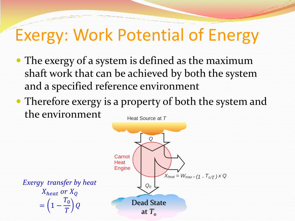
Exergy: Work Potential of Energy
The exergy of a system is defined as the maximum shaft work that can be achieved by both the system and a specified reference environment
Therefore exergy is a property of both the system and the environment
Exergy transfer by heat 𝑋ℎ𝑒𝑎𝑡 𝑜𝑟 𝑋𝑄
= 1 −𝑇0𝑇
𝑄
CarnotHeatEngine
Heat Source at T
Environment at T0
Q
Q0
X = W (1 - heat max = T0/T ) x Q
Dead State at T0
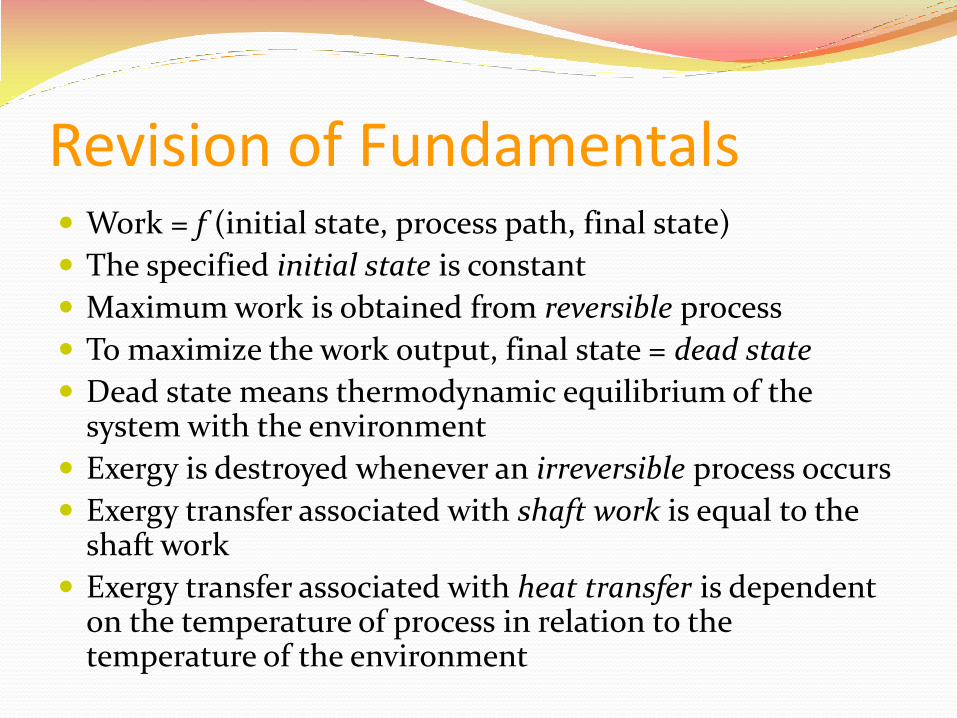
Revision of Fundamentals Work = f (initial state, process path, final state)
The specified initial state is constant
Maximum work is obtained from reversible process
To maximize the work output, final state = dead state
Dead state means thermodynamic equilibrium of the system with the environment
Exergy is destroyed whenever an irreversible process occurs
Exergy transfer associated with shaft work is equal to the shaft work
Exergy transfer associated with heat transfer is dependent on the temperature of process in relation to the temperature of the environment

Exergy Associated with KE and PE
Kinetic and potential energies are forms of mechanical energy
Hence they can be converted to work entirely, i.e. The work potential or exergy are themselves:
zgx
Vx
pe
ke
pe
2ke
2
zgx
x
pe
ke
ep:energypotentialofexergy
2ek:energykineticofexergy
2
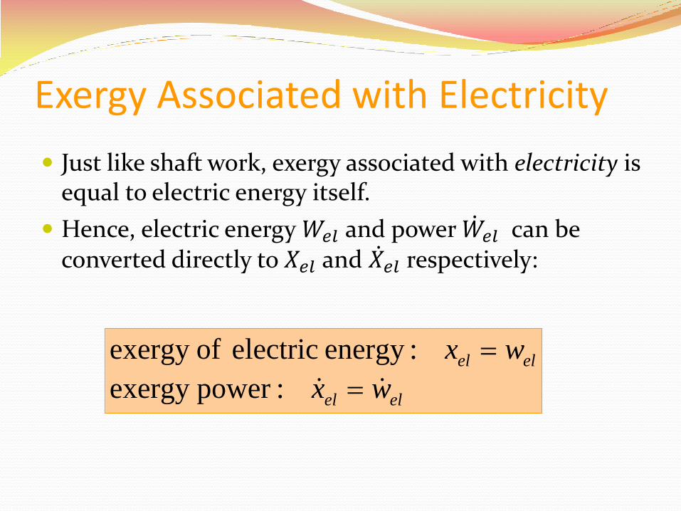
Exergy Associated with Electricity
Just like shaft work, exergy associated with electricity is equal to electric energy itself.
Hence, electric energy 𝑊𝑒𝑙 and power 𝑊 𝑒𝑙 can be converted directly to 𝑋𝑒𝑙 and 𝑋 𝑒𝑙 respectively:
zgx
Vx
pe
ke
pe
2ke
2
elel
elel
wx
wx
:powerexergy
:energyelectricofexergy
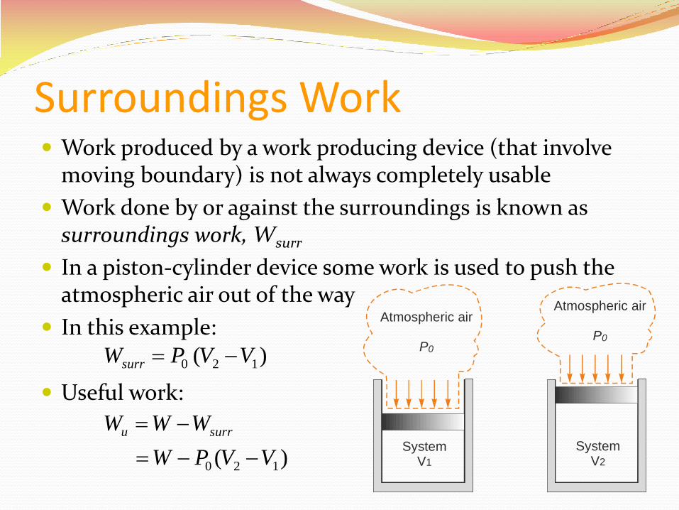
Surroundings Work Work produced by a work producing device (that involve
moving boundary) is not always completely usable
Work done by or against the surroundings is known as surroundings work, Wsurr
In a piston-cylinder device some work is used to push the atmospheric air out of the way
In this example:
Useful work:
SystemV1
SystemV2
Atmospheric air
P0
Atmospheric air
P0
)( 120 VVPWsurr
)( 120 VVPW
WWW surru
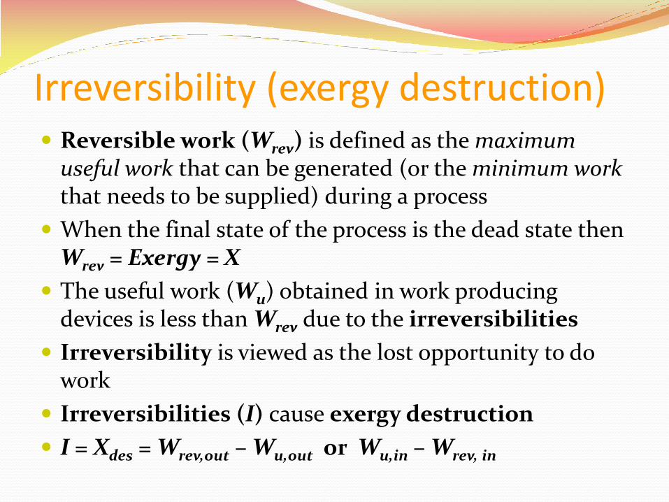
Irreversibility (exergy destruction) Reversible work (Wrev) is defined as the maximum
useful work that can be generated (or the minimum work that needs to be supplied) during a process
When the final state of the process is the dead state then Wrev = Exergy = X
The useful work (Wu) obtained in work producing devices is less than Wrev due to the irreversibilities
Irreversibility is viewed as the lost opportunity to do work
Irreversibilities (I) cause exergy destruction
I = Xdes = Wrev,out – Wu,out or Wu,in – Wrev, in
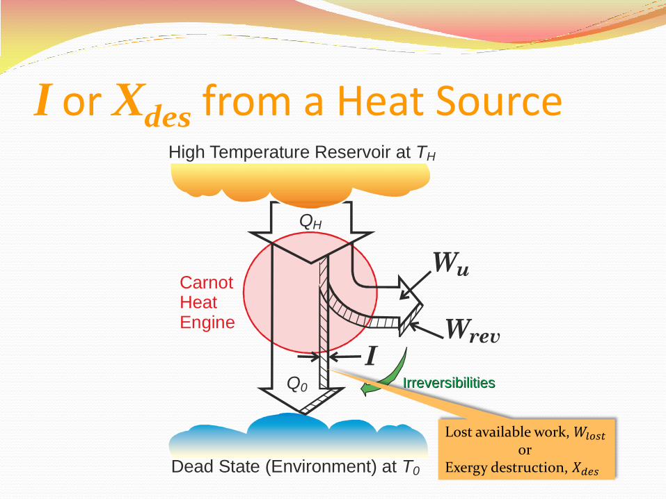
I or Xdes from a Heat Source
CarnotHeatEngine
High Temperature Reservoir at TH
Dead State (Environment) at T0
QH
Q0 IrreversibilitiesIrreversibilities
Lost available work, 𝑊𝑙𝑜𝑠𝑡 or
Exergy destruction, 𝑋𝑑𝑒𝑠
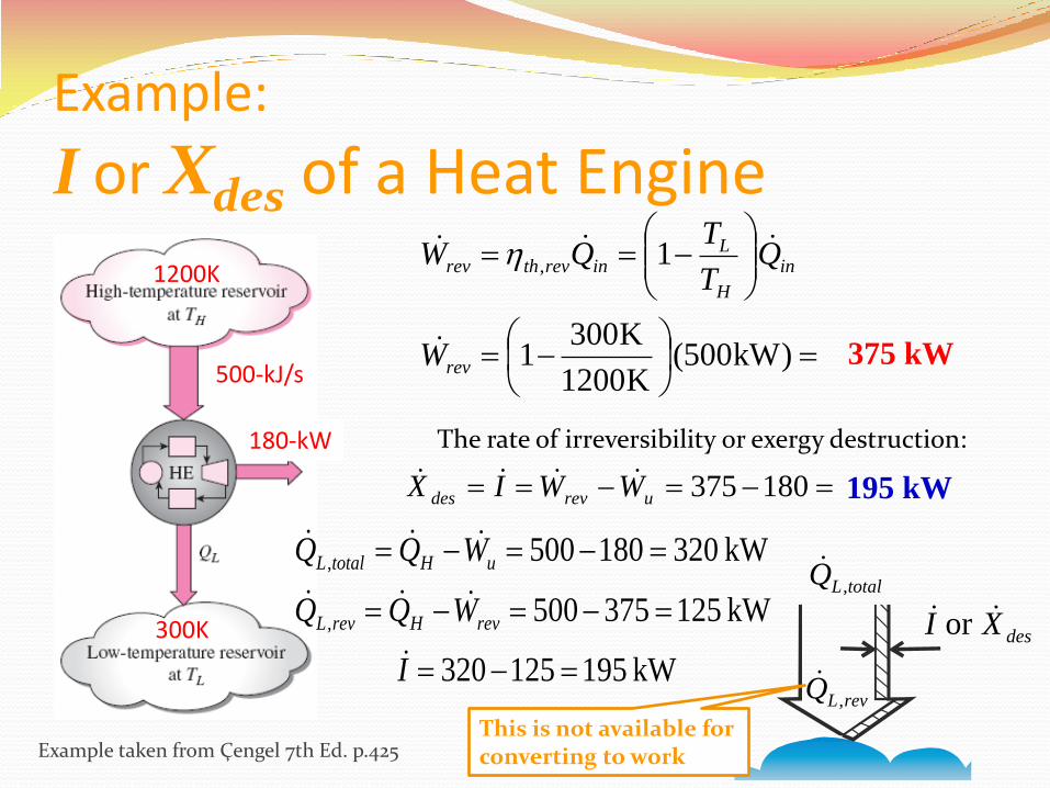
Example:
I or Xdes of a Heat Engine
1200K
300K
180-kW
500-kJ/s
)kW500(K1200
K3001
1,
rev
in
H
Linrevthrev
W
QT
TQW
375 kW
180375urevdes WWIX 195 kW
The rate of irreversibility or exergy destruction:
Example taken from Çengel 7th Ed. p.425
totalLQ ,
desXI or
revLQ ,kW 195125320
kW 125375500
kW 320180500
,
,
I
WQQ
WQQ
revHrevL
uHtotalL
This is not available for converting to work
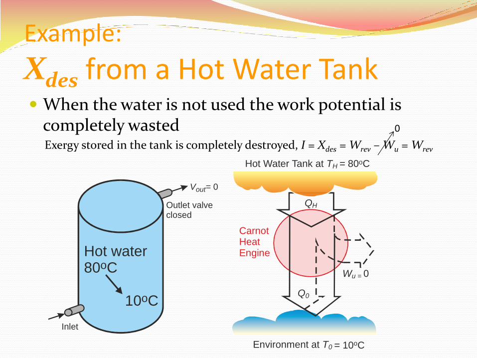
Example:
Xdes from a Hot Water Tank When the water is not used the work potential is
completely wasted
CarnotHeatEngine
Hot Water Tank at TH = 80 Co
Environment at T0 = 10 Co
QH
Q0
Wu = 0
Inlet
Outlet valveclosed
Hot water80 C 10 C
o
o
V = out 0
Exergy stored in the tank is completely destroyed, I = Xdes = Wrev – Wu = Wrev
0
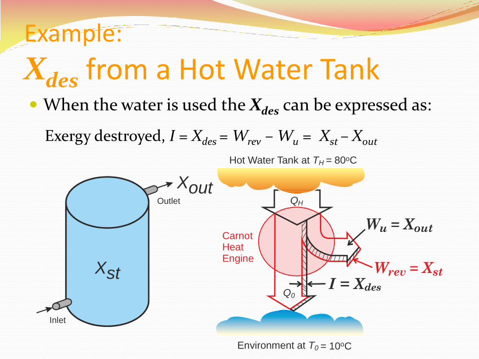
Example:
Xdes from a Hot Water Tank When the water is used the Xdes can be expressed as:
Exergy destroyed, I = Xdes = Wrev – Wu = Xst – Xout
Inlet
Outlet
Xst
Xout
CarnotHeatEngine
QH
Q0
Hot Water Tank at TH = 80 Co
Environment at T0 = 10 Co
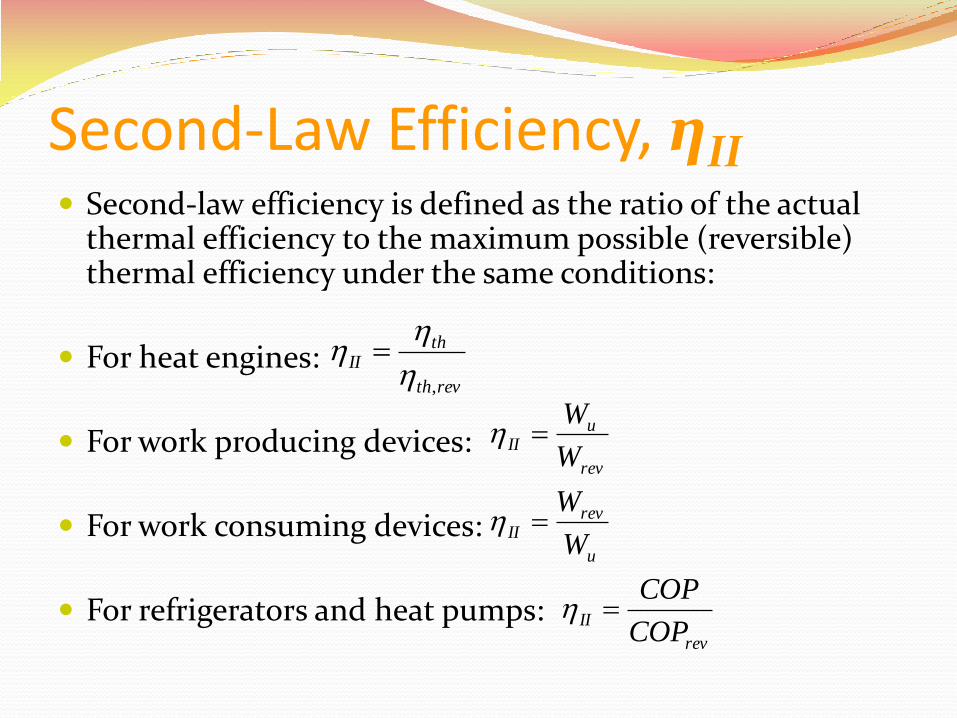
Second-Law Efficiency, ηII Second-law efficiency is defined as the ratio of the actual
thermal efficiency to the maximum possible (reversible) thermal efficiency under the same conditions:
For heat engines:
For work producing devices:
For work consuming devices:
For refrigerators and heat pumps:
revth
thII
,
rev
uII
W
W
rev
IICOP
COP
u
revII
W
W
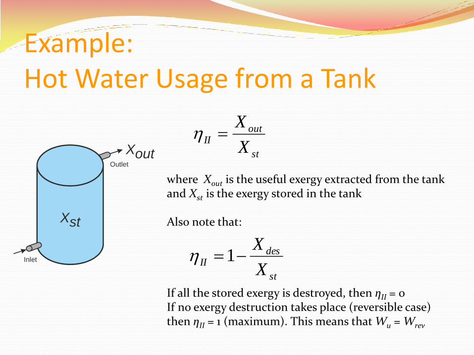
Example: Hot Water Usage from a Tank
Inlet
Outlet
Xst
Xout st
outII
X
X
where Xout is the useful exergy extracted from the tank and Xst is the exergy stored in the tank Also note that: If all the stored exergy is destroyed, then ηII = 0 If no exergy destruction takes place (reversible case) then ηII = 1 (maximum). This means that Wu = Wrev
st
desII
X
X1
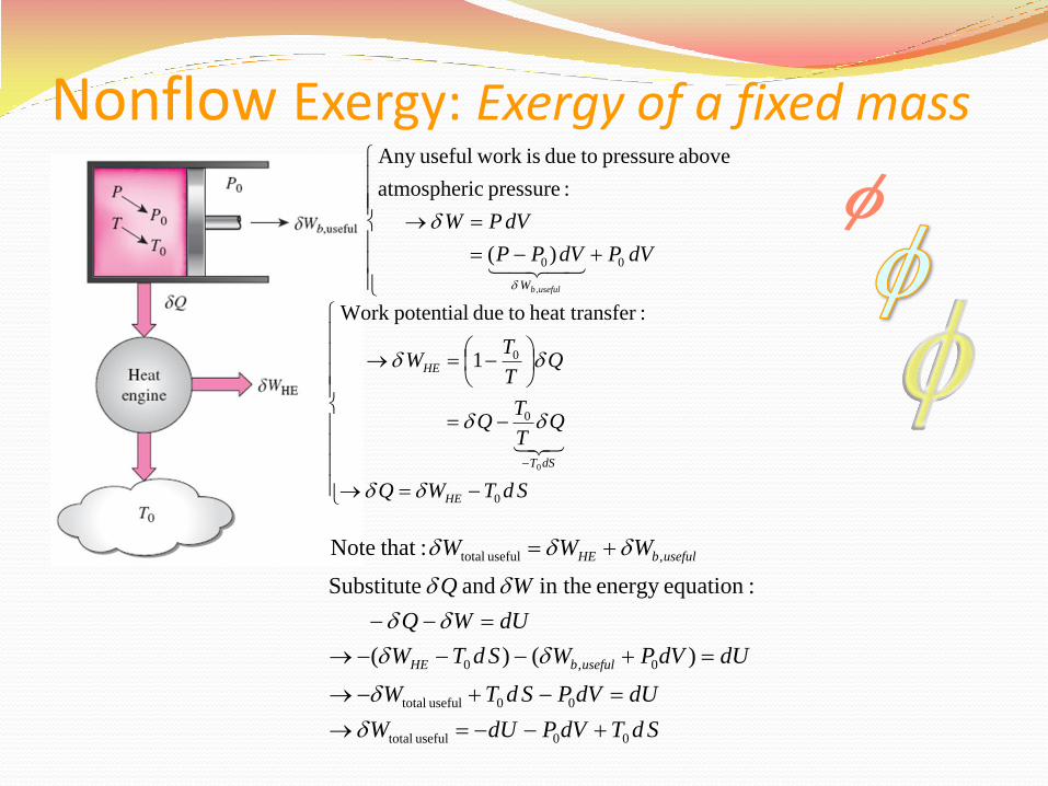
Nonflow Exergy: Exergy of a fixed mass
dVPdVPP
dVPW
usefulbW
00
,
)(
:pressure catmospheri
above pressure todue is work usefulAny
SdTWQ
QT
TQ
QT
TW
HE
dST
HE
0
0
0
0
1
:ferheat trans todue potentialWork
SdTdVPdUW
dUdVPSdTW
dUdVPWSdTW
dUWQ
WQ
WWW
usefulbHE
usefulbHE
00useful total
00useful total
0,0
,useful total
)()(
:equationenergy in the and Substitute
: thatNote
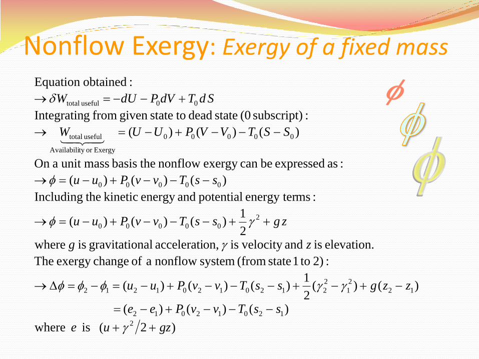
Nonflow Exergy: Exergy of a fixed mass
)2( is where
)()()(
)()(2
1)()()(
:2) to1 state (from system nonflow a of changeexergy The
elevation. is and velocity is on,accelerati nalgravitatio is where2
1)()()(
:msenergy ter potential andenergy kinetic theIncluding
)()()(
:as expressed becan exergy nonflow thebasis massunit aOn
)()()(
:subscript) (0 state dead tostategiven from gIntegratin
:obtainedEquation
2
12012012
12
2
1
2
21201201212
2
00000
00000
00000
Exergyor ty Availabili
useful total
00useful total
gzue
ssTvvPee
zzgssTvvPuu
zg
zgssTvvPuu
ssTvvPuu
SSTVVPUUW
SdTdVPdUW
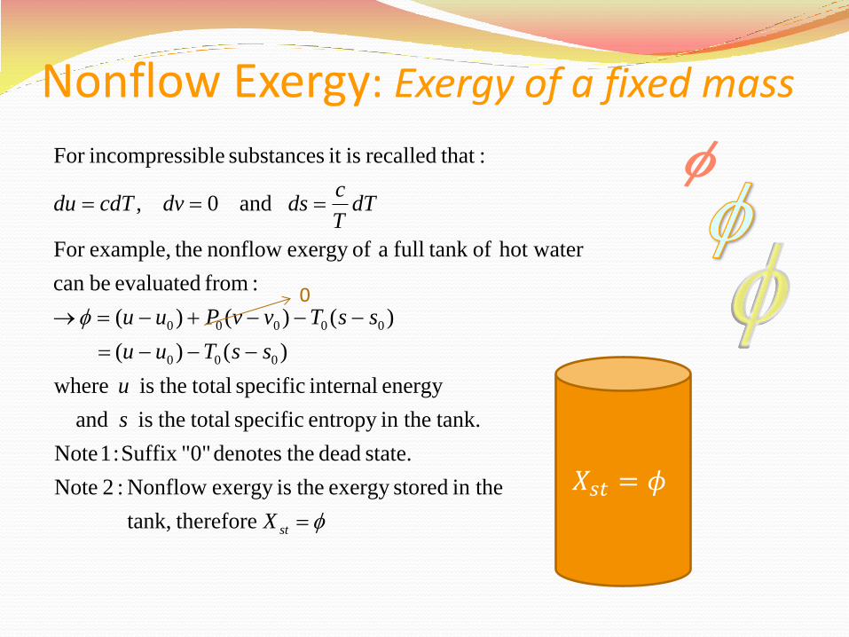
Nonflow Exergy: Exergy of a fixed mass
stX
s
u
ssTuu
ssTvvPuu
dTT
cdsdvcdTdu
therefore tank,
in the storedexergy theisexergy Nonflow :2 Note
state. dead thedenotes "0"Suffix :1 Note
tank.in theentropy specific total theis and
energy internal specific total theis where
)()(
)()()(
:from evaluated becan
hot water of tank full a ofexergy nonflow theexample,For
and 0 ,
: thatrecalled isit substances ibleincompressFor
000
00000
𝑋𝑠𝑡 = 𝜙
0
Flow Exergy: Exergy of a flow stream
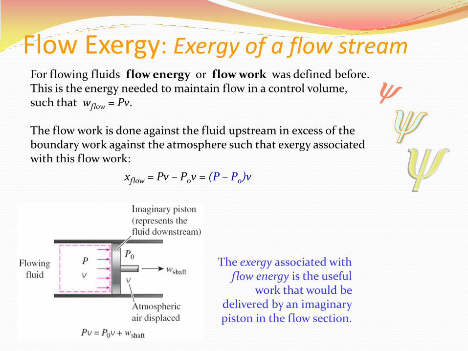
The exergy associated with flow energy is the useful
work that would be delivered by an imaginary piston in the flow section.
For flowing fluids flow energy or flow work was defined before. This is the energy needed to maintain flow in a control volume, such that wflow = Pv. The flow work is done against the fluid upstream in excess of the boundary work against the atmosphere such that exergy associated with this flow work:
xflow = Pv – P0v = (P – P0)v
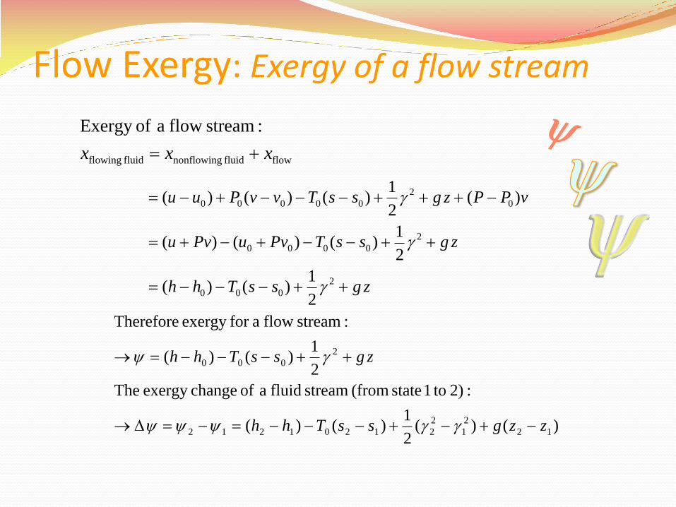
Flow Exergy: Exergy of a flow stream
flowfluid nonflowingfluid flowing
:stream flow a ofExergy
xxx
zgssThh
zgssTPvuPvu
vPPzgssTvvPuu
2
000
2
0000
0
2
00000
2
1)()(
2
1)()()(
)(2
1)()()(
)()(2
1)()(
:2) to1 state (from stream fluid a of changeexergy The
2
1)()(
:stream flow afor exergy Therefore
12
2
1
2
21201212
2
000
zzgssThh
zgssThh
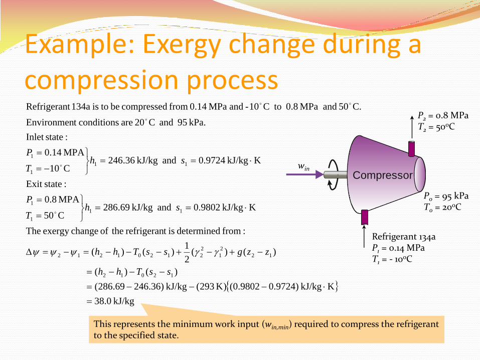
Example: Exergy change during a compression process
kJ/kg 38.0
KkJ/kg )9724.09802.0()K 293( kJ/kg )36.24669.286(
)()(
)()(2
1)()(
:from determined ist refrigeran theof changeexergy The
KkJ/kg 9802.0 and kJ/kg 69.286C50
MPA 8.0
:stateExit
KkJ/kg 9724.0 and kJ/kg 36.246C10
MPA 14.0
:stateInlet
kPa. 95 and C20 are conditionst Environmen
C.50 and MPa 0.8 toC10- and MPa 0.14 from compressed be tois 134at Refrigeran
12012
12
2
1
2
21201212
11
1
1
11
1
1
ssThh
zzgssThh
shT
P
shT
P
This represents the minimum work input (win,min) required to compress the refrigerant to the specified state.
Compressor
Refrigerant 134a P1 = 0.14 MPa T1 = - 10oC
P2 = 0.8 MPa T2 = 50oC
P0 = 95 kPa T0 = 20oC
win
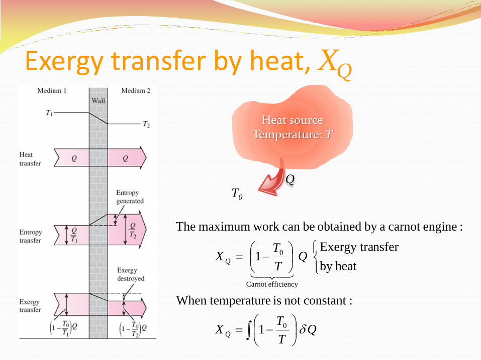
Exergy transfer by heat, XQ
QT
TX
QT
TX
Q
Q
0
efficiencyCarnot
0
1
:constantnot is ratureWhen tempe
heatby
nsfer Exergy tra1
:enginecarnot aby obtained becan work maximum The
Heat source Temperature: T
Q T0
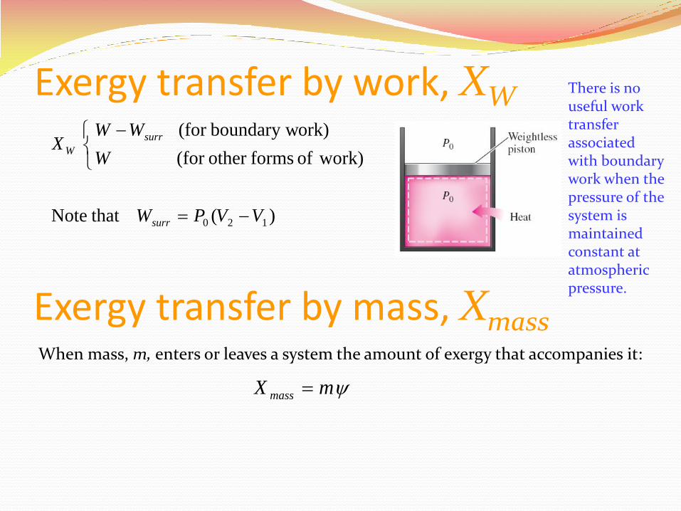
Exergy transfer by work, XW
)( that Note
work)of formsother (for
ork)boundary w(for
120 VVPW
W
WWX
surr
surr
W
There is no useful work transfer associated with boundary work when the pressure of the system is maintained constant at atmospheric pressure.
Exergy transfer by mass, Xmass When mass, m, enters or leaves a system the amount of exergy that accompanies it:
mX mass
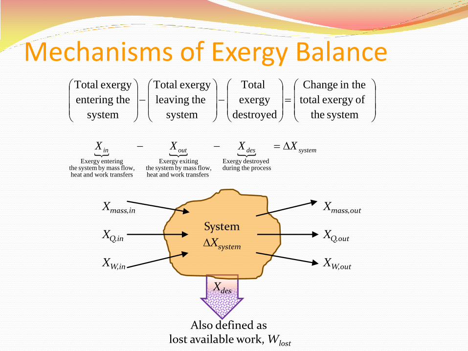
Mechanisms of Exergy Balance
Xmass,in
XQ,in
XW,in
Xmass,out
XQ,out
XW,out
systemdesoutin XXXX
process theduringdestroyedExergy
sfers work tranandheat flow, massby system the
exitingExergy
sfers work tranandheat flow, massby system the
enteringExergy
system the
ofexergy total
in the Change
destroyed
exergy
Total
system
theleaving
exergy Total
system
theentering
exergy Total
Also defined as lost available work, Wlost
Xdes
System
Xsystem
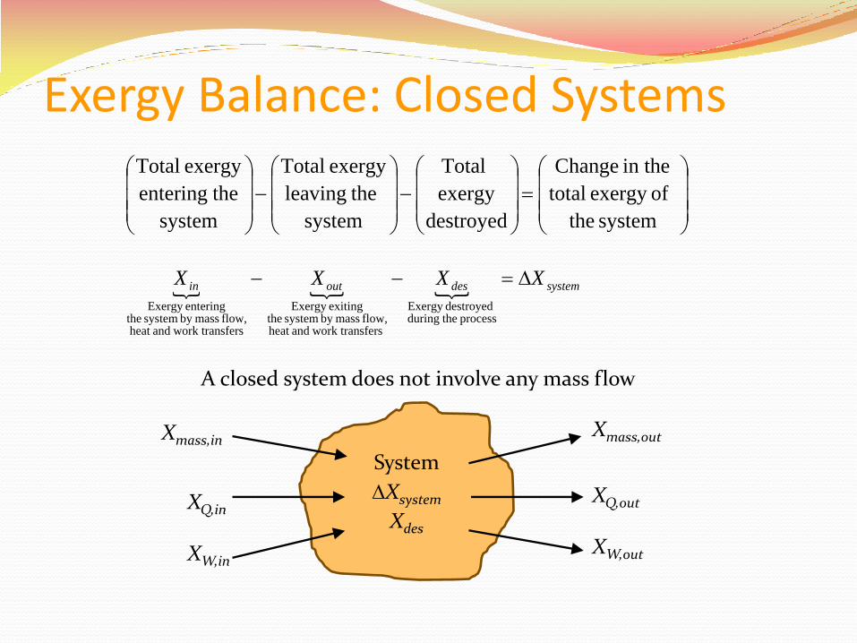
Exergy Balance: Closed Systems
System
Xsystem
Xdes
XQ,in
XW,in
XQ,out
XW,out
systemdesoutin XXXX
process theduringdestroyedExergy
sfers work tranandheat flow, massby system the
exitingExergy
sfers work tranandheat flow, massby system the
enteringExergy
system the
ofexergy total
in the Change
destroyed
exergy
Total
system
theleaving
exergy Total
system
theentering
exergy Total
A closed system does not involve any mass flow
Xmass,in Xmass,out
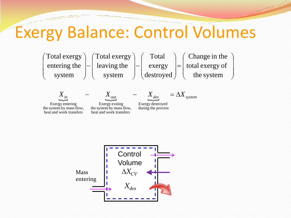
Exergy Balance: Control Volumes
systemdesoutin XXXX
process theduringdestroyedExergy
sfers work tranandheat flow, massby system the
exitingExergy
sfers work tranandheat flow, massby system the
enteringExergy
system the
ofexergy total
in the Change
destroyed
exergy
Total
system
theleaving
exergy Total
system
theentering
exergy Total
Control
Volume
XCV
Xdes
Mass entering
Procedure for Exergy Analysis
Subdivide the process under consideration into sections as desired
Conduct conventional energy analysis
Select a reference environment
Evaluate energy and exergy values relative to the environment
Set up the exergy balance and determine exergy destruction
Define first and second law efficiencies of the system
Interpretation of results and conclusions
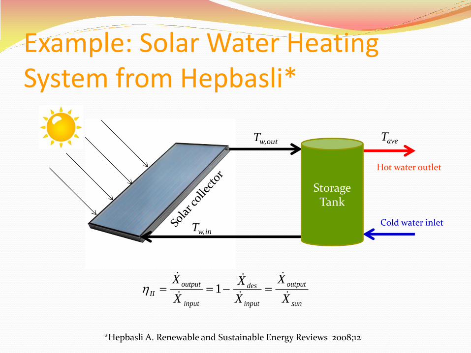
Example: Solar Water Heating System from Hepbasli*
Tave Tw,out
Tw,in
*Hepbasli A. Renewable and Sustainable Energy Reviews 2008;12
sun
output
input
des
input
output
IIX
X
X
X
X
X
1
Storage Tank
Cold water inlet
Hot water outlet
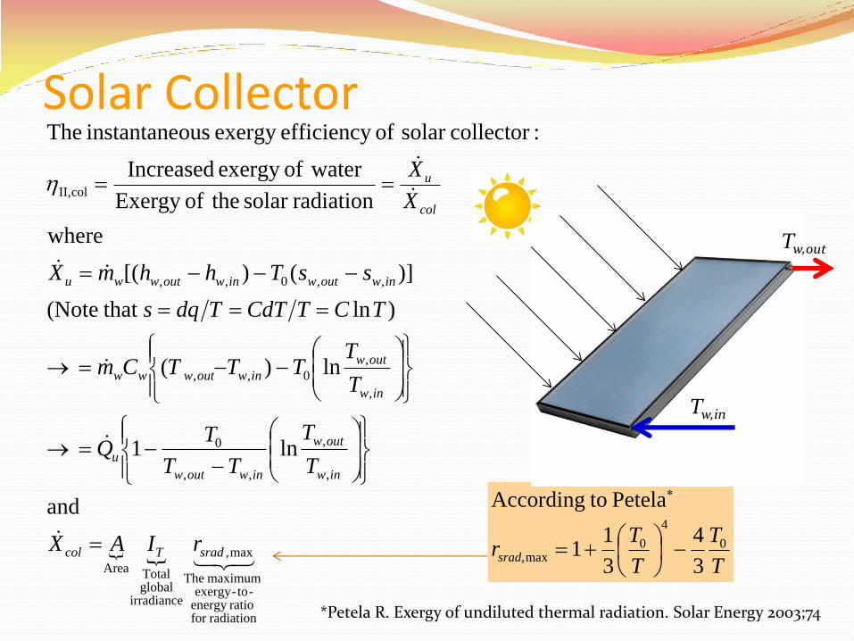
Solar Collector
and
ln1
ln)(
)ln that (Note
)]()[(
where
radiationsolar theofExergy
waterofexergy Increased
:collectorsolar of efficiencyexergy ousinstantane The
radiationfor ratioenergy
-to-exergy maximum The
max,
irradianceglobalTotalArea
,
,
,,
0
,
,
0,,
,,0,,
colII,
sradTcol
inw
outw
inwoutw
u
inw
outw
inwoutwww
inwoutwinwoutwwu
col
u
rIAX
T
T
TT
TQ
T
TTTTCm
TCTCdTTdqs
ssThhmX
X
X
T
T
T
Trsrad,
0
4
0max
3
4
3
11
Petela toAccording
*Petela R. Exergy of undiluted thermal radiation. Solar Energy 2003;74
Tw,out
Tw,in
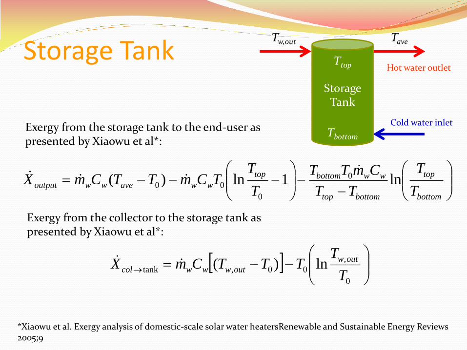
Storage Tank
bottom
top
bottomtop
wwbottomtop
wwavewwoutputT
T
TT
CmTT
T
TTCmTTCmX ln1ln)( 0
0
00
Tave
Storage Tank
Cold water inlet
Hot water outlet
Exergy from the storage tank to the end-user as presented by Xiaowu et al*:
Ttop
Tbottom
*Xiaowu et al. Exergy analysis of domestic-scale solar water heatersRenewable and Sustainable Energy Reviews 2005;9
Exergy from the collector to the storage tank as presented by Xiaowu et al*:
0
,
00,tank ln)(T
TTTTCmX outw
outwwwcol
Tw,out