chapter 4-machining of ceramics
TRANSCRIPT
8/10/2019 Chapter 4-Machining of Ceramics
http://slidepdf.com/reader/full/chapter-4-machining-of-ceramics 1/26
Machining of ceramics
Advanced Material Removal Processes Page 1
Chapter 4
MACHINING OF CERAMICS
Introduction:
A ceramic is an inorganic, non-metallic solid prepared by the action of
heat and subsequent cooling. Ceramic materials may have a crystalline or
partly crystalline structure, or may be amorphous (e.g., a glass). Because most
common ceramics are crystalline, the definition of ceramic is often restricted to
inorganic crystalline materials, as opposed to the noncrystalline glasses, a
distinction followed here.
The word "ceramic" comes from the Greek word (keramikos) "of
pottery" or "for pottery" (keramos) "potter's clay, tile and pottery".
Types of ceramic material:
A ceramic material is an inorganic, non-metallic, often crystalline oxide,
nitride or carbide material. Some elements, such as carbon or silicon, may be
considered ceramics.
Traditional ceramic raw materials include clay minerals such as
kaolinite, whereas more recent materials include aluminium oxide, more
commonly known as alumina. The modern ceramic materials, which are
classified as advanced ceramics, include silicon carbide and tungsten carbide.
Both are valued for their abrasion resistance, and hence find use in applications
such as the wear plates of crushing equipment in mining operations.
1) Crystalline ceramics:
Crystalline ceramic materials are not amenable to a great range of
processing. Methods for dealing with them tend to fall into one of two
categories – either makes the ceramic in the desired shape, by reaction in
situ, or by "forming" powders into the desired shape, and then sintering
to form a solid body. Ceramic forming techniques include shaping by
hand (sometimes including a rotation process called "throwing"), slip
casting, tape casting (used for making very thin ceramic capacitors,
e.g.), injection moulding, dry pressing, and other variations.. A few
methods use a hybrid between the two approaches.
8/10/2019 Chapter 4-Machining of Ceramics
http://slidepdf.com/reader/full/chapter-4-machining-of-ceramics 2/26
Machining of ceramics
Advanced Material Removal Processes Page 2
2) Non-crystalline ceramics:
Non-crystalline ceramics, being glass, tend to be formed from
melts. The glass is shaped when either fully molten, by casting, or when
in a state of toffee-like viscosity, by methods such as blowing into amould. If later heat treatments cause this glass to become partly
crystalline, the resulting material is known as a glass-ceramic, widely
used as cook-top and also as a glass composite material for nuclear waste
disposal.
Types of ceramic product:
For convenience, ceramic products are usually divided into four sectors;
these are shown below with some examples:
Structural, including bricks, pipes, floor and roof tiles
Refractories, such as kiln linings, gas fire radiant, steel and glass making
crucibles
Whitewares, including tableware, cookware, wall tiles, pottery products
and sanitary ware
Technical, is also known as engineering, advanced, special, and in Japan,
fine ceramics. Such items include tiles used in the Space Shuttleprogram, gas burner nozzles, ballistic protection, nuclear fuel uranium
oxide pellets, biomedical implants, coatings of jet engine turbine
blades, ceramic disk brake, missile nose cones, bearing
(mechanical),etc. Frequently, the raw materials do not include clays.
Classification of technical ceramics:
Technical ceramics can also be classified into three distinct material
categories:
Oxides: alumina, beryllia, ceria, zirconia
Nonoxides: carbide, boride, nitride, silicide
Composite materials: particulate reinforced, fibre reinforced,
combinations of oxides and non-oxides
8/10/2019 Chapter 4-Machining of Ceramics
http://slidepdf.com/reader/full/chapter-4-machining-of-ceramics 3/26
Machining of ceramics
Advanced Material Removal Processes Page 3
Properties of Ceramics:
Ceramics have some attractive properties compared to metals and
polymers, which make them useful for specific applications. Their physical
properties have been utilized for many applications. In other applications their
mechanical properties are important.
The most important advantageous features of ceramic materials are:
Low electrical conductivity,
Low thermal conductivity,
Low density,
High strength at high temperatures,
Wear resistance,
Corrosion resistance,
Specific physical properties (optical, electrical, magnetic).
The main disadvantages of ceramics are:
Low tensile strength at room temperature for some materials,
Brittleness,
Large scatter of strengths, Subcritical crack extension.
1) Physical properties:
Physical properties means the behaviour of materials in response to
physical forces other than mechanical, such as; Volumetric, thermal,
electric and electrochemical properties.
Most Ceramics are lighter than metals but heavier than polymers. Most ceramics have a higher melting point than most metals as it is
that some ceramics such as China can with stand high temperatures
to about 1200 degrees centigrade.
Ceramics also has lower Electrical and Thermal Conductivity than
most metals but the range of value is greater in ceramics permitting
some ceramics to be used as insulators, for example Porcelain
insulators and others as conductors like Lithium-ion conducting
glass-ceramics and oxide ceramics.
8/10/2019 Chapter 4-Machining of Ceramics
http://slidepdf.com/reader/full/chapter-4-machining-of-ceramics 4/26
Machining of ceramics
Advanced Material Removal Processes Page 4
Thermal expansion is another physical property of ceramics,
Ceramic thermal expansion coefficients are less than those of
metals but effects are more damaging in ceramics bringing about
cracks and other failures (Thermal shock and thermal cracking) as
for ceramic materials with relatively high thermal expansion and
low thermal conductivity however there is glass ceramics that has
low thermal expansion thus resisting thermal shock and thermal
cracking, for example Pyrex glass ceramics.
2) Mechanical properties:
Mechanical properties are important in structural and buildingmaterials as well as textile fabrics. They include the properties used to
describe the strength of materials such as: elasticity / plasticity, tensile
strength, compressive strength, shear strength, fracture toughness &
ductility (low in brittle materials), and indentation hardness.
Ceramic materials are usually ionic or covalent bonded materials,
and can be crystalline or amorphous. A material held together by either
type of bond will tend to fracture before any plastic deformation takes place, which results in poor toughness in these materials. Additionally,
because these materials tend to be porous, the pores and other
microscopic imperfections act as stress concentrators, decreasing the
toughness further, and reducing the tensile strength. These combine to
give catastrophic failures, as opposed to the normally much more gentle
failure modes of metals.
Brittleness means that failure occurs without prior measurable
plastic deformation. This is due to the strong atomic bonding of ceramics,which lead to high stresses for the motion of dislocations. Thus, failure
can start from small flaws before plastic deformation is possible. This fact
can also be expressed in low resistance against crack extension, which is
characterised by the fracture toughness. The absence of local plastic
deformation leads to failure at locations of high local stresses, e.g. at
notches, at contacts between different material or during thermal shock.
In metals these strain controlled local stresses lead to small plastic strains.
8/10/2019 Chapter 4-Machining of Ceramics
http://slidepdf.com/reader/full/chapter-4-machining-of-ceramics 5/26
Machining of ceramics
Advanced Material Removal Processes Page 5
The large scatter of strength is caused by the statistical
distribution of the flaw size and the flaw location. This requires a
statistical description of the strength and a relation between failure
probability and the stress distribution in a component.
Subcritical crack extension can cause failure under constant or
cyclic loading during the operation of a component and will lead,
consequently, to a limited lifetime.
To overcome the brittle behaviour, ceramic material development
has introduced the class of ceramic matrix composite materials, in
which ceramic fibres are embedded and with specific coatings are
forming fibre bridges across any crack. This mechanism substantially
increases the fracture toughness of such ceramics. The ceramic disc
brakes are, for example using a ceramic matrix composite material
manufactured with a specific process.
3) Electrical properties:
Semiconductors:-
Some ceramics are semiconductors. Most of these are
transition metal oxides that are II-VI semiconductors, such as zinc
oxide.
While there are prospects of mass-producing blue LEDs from
zinc oxide, ceramicists are most interested in the electrical properties
that show grain boundary effects.
One of the most widely used of these is the varistor. These are
devices that exhibit the property that resistance drops sharply at a
certain threshold voltage. This makes them ideal for surge-
protection applications; as there is control over the threshold voltage
and energy tolerance, they find use in all sorts of applications. The
best demonstration of their ability can be found in electrical
substations, where they are employed to protect the infrastructure
from lightning strikes. They have rapid response, are low
8/10/2019 Chapter 4-Machining of Ceramics
http://slidepdf.com/reader/full/chapter-4-machining-of-ceramics 6/26
Machining of ceramics
Advanced Material Removal Processes Page 6
maintenance, and do not appreciably degrade from use, making them
virtually ideal devices for this application.
Semiconducting ceramics are also employed as gas sensors.
When various gases are passed over a polycrystalline ceramic, its
electrical resistance changes. With tuning to the possible gas mixtures,
very inexpensive devices can be produced.
Superconductivity:-
Under some conditions, such as extremely low temperature,
some ceramics exhibit high temperature superconductivity. The
exact reason for this is not known, but there are two major families ofsuperconducting ceramics.
Ferro-electricity and supersets -
Piezoelectricity, a link between electrical and mechanical
response, is exhibited by a large number of ceramic materials,
including the quartz used to measure time in watches and other
electronics. Such devices use both properties of piezoelectric, using
electricity to produce a mechanical motion (powering the device)
and then using this mechanical motion to produce electricity
(generating a signal). The unit of time measured is the natural
interval required for electricity to be converted into mechanical
energy and back again.
The most common such materials are lead zirconate
titanate and barium titanate. Aside from the uses mentioned
above, their strong piezoelectric response is exploited in the designof high-frequency loudspeakers, transducers for sonar, and
actuators for atomic force and scanning tunnelling microscopes.
4) Optical properties:
Optically transparent materials focus on the response of a
material to incoming light waves of a range of wavelengths. Frequency
selective optical filters can be utilized to alter or enhance the brightness
and contrast of a digital image.
8/10/2019 Chapter 4-Machining of Ceramics
http://slidepdf.com/reader/full/chapter-4-machining-of-ceramics 7/26
Machining of ceramics
Advanced Material Removal Processes Page 7
Thus, there is an increasing need in the military sector for high-
strength, robust materials which have the capability to transmit light
(electromagnetic waves) in the visible (0.4 – 0.7 micrometres) and mid-
infrared (1 – 5 micrometres) regions of the spectrum. These materials are
needed for applications requiring transparent armour, including next-
generation high-speed missiles and pods, as well as protection against
improvised explosive devices (IED).
In the 1960s, scientists at General Electric (GE) discovered that
under the right manufacturing conditions, some ceramics, especially
aluminium oxide (alumina), could be made translucent. During the past
two decades, additional types of transparent ceramics have been
developed for applications such as nose cones for heat-seeking missiles,
windows for fighter aircraft, and scintillation counters for computed
tomography scanners.
Applications of Ceramics:
Knife blades: the blade of a ceramic knife will stay sharp for much
longer than that of a steel knife, although it is more brittle and can snap
from a fall onto a hard surface. Ceramic brake disks for vehicles are resistant to abrasion at high
temperatures.
Advanced composite ceramic and metal matrices have been designed
for most modern armoured fighting vehicles because they offer superior
penetrating resistance against shaped charges (such as HEAT rounds)
and kinetic energy penetrators.
Ceramics such as alumina and boron carbide have been used in ballistic
armoured vests to repel large-calibre rifle fire. Such plates are knowncommonly as small arms protective inserts, or SAPIs. Similar material
is used to protect the cockpits of some military airplanes, because of the
low weight of the material.
Ceramics can be used in place of steel for ball bearings. Their higher
hardness means they are much less susceptible to wear and typically last
for triple the lifetime of a steel part. Two drawbacks to ceramic bearings
are a significantly higher cost and susceptibility to damage under shock
loads.
8/10/2019 Chapter 4-Machining of Ceramics
http://slidepdf.com/reader/full/chapter-4-machining-of-ceramics 8/26
Machining of ceramics
Advanced Material Removal Processes Page 8
Recent advances have been made in ceramics which include bio-
ceramics, such as dental implants and synthetic bones. Hydroxyapatite,
the natural mineral component of bone, has been made synthetically from
a number of biological and chemical sources and can be formed into
ceramic materials. Orthopaedic implants coated with these materials bond
readily to bone and other tissues in the body without rejection or
inflammatory reactions
High-tech ceramic is used in watchmaking for producing watch cases.
The material is valued by watchmakers for its light weight, scratch
resistance, durability and smooth touch.
Machining Techniques:
Ceramics are manufactured by compacting powder to a body which is
then sintered at high temperatures. The geometry, production volume and
characteristic requirements for the component govern the choice of
manufacturing process.
Ultrasonic machining:
1. Introduction:
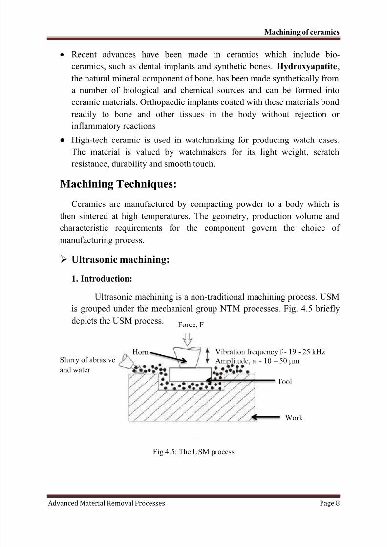
Ultrasonic machining is a non-traditional machining process. USM
is grouped under the mechanical group NTM processes. Fig. 4.5 briefly
depicts the USM process.
Fig 4.5: The USM process
Slurry of abrasive
and water
Horn
Force, F
Vibration frequency f~ 19 - 25 kHz
Amplitude, a ~ 10 – 50 μm
Tool
Work
8/10/2019 Chapter 4-Machining of Ceramics
http://slidepdf.com/reader/full/chapter-4-machining-of-ceramics 9/26
Machining of ceramics
Advanced Material Removal Processes Page 9
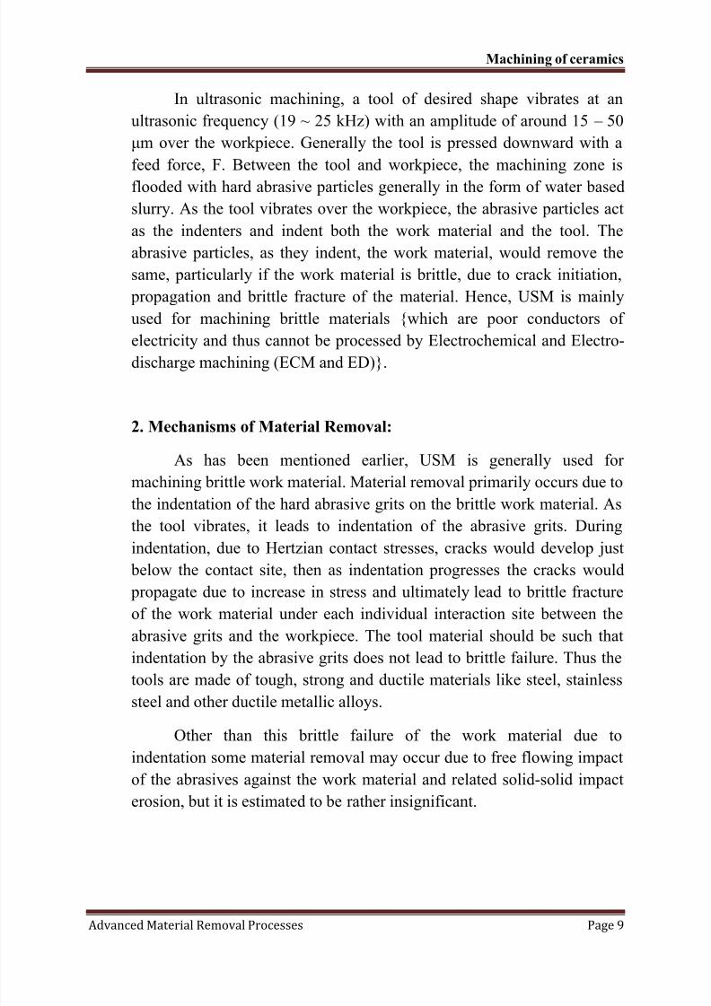
In ultrasonic machining, a tool of desired shape vibrates at an
ultrasonic frequency (19 ~ 25 kHz) with an amplitude of around 15 – 50
μm over the workpiece. Generally the tool is pressed downward with a
feed force, F. Between the tool and workpiece, the machining zone is
flooded with hard abrasive particles generally in the form of water based
slurry. As the tool vibrates over the workpiece, the abrasive particles act
as the indenters and indent both the work material and the tool. The
abrasive particles, as they indent, the work material, would remove the
same, particularly if the work material is brittle, due to crack initiation,
propagation and brittle fracture of the material. Hence, USM is mainly
used for machining brittle materials {which are poor conductors of
electricity and thus cannot be processed by Electrochemical and Electro-
discharge machining (ECM and ED)}.
2. Mechanisms of Material Removal:
As has been mentioned earlier, USM is generally used for
machining brittle work material. Material removal primarily occurs due to
the indentation of the hard abrasive grits on the brittle work material. As
the tool vibrates, it leads to indentation of the abrasive grits. Duringindentation, due to Hertzian contact stresses, cracks would develop just
below the contact site, then as indentation progresses the cracks would
propagate due to increase in stress and ultimately lead to brittle fracture
of the work material under each individual interaction site between the
abrasive grits and the workpiece. The tool material should be such that
indentation by the abrasive grits does not lead to brittle failure. Thus the
tools are made of tough, strong and ductile materials like steel, stainless
steel and other ductile metallic alloys.
Other than this brittle failure of the work material due to
indentation some material removal may occur due to free flowing impact
of the abrasives against the work material and related solid-solid impact
erosion, but it is estimated to be rather insignificant.
8/10/2019 Chapter 4-Machining of Ceramics
http://slidepdf.com/reader/full/chapter-4-machining-of-ceramics 10/26
Machining of ceramics
Advanced Material Removal Processes Page 10
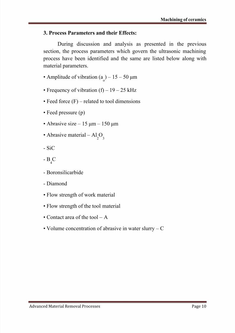
3. Process Parameters and their Effects:
During discussion and analysis as presented in the previous
section, the process parameters which govern the ultrasonic machining
process have been identified and the same are listed below along withmaterial parameters.
• Amplitude of vibration (ao) – 15 – 50 μm
• Frequency of vibration (f) – 19 – 25 kHz
• Feed force (F) – related to tool dimensions
• Feed pressure (p)
• Abrasive size – 15 μm – 150 μm
• Abrasive material – Al2O
3
- SiC
- B4C
- Boronsilicarbide
- Diamond
• Flow strength of work material
• Flow strength of the tool material
• Contact area of the tool – A
• Volume concentration of abrasive in water slurry – C
8/10/2019 Chapter 4-Machining of Ceramics
http://slidepdf.com/reader/full/chapter-4-machining-of-ceramics 11/26
Machining of ceramics
Advanced Material Removal Processes Page 11
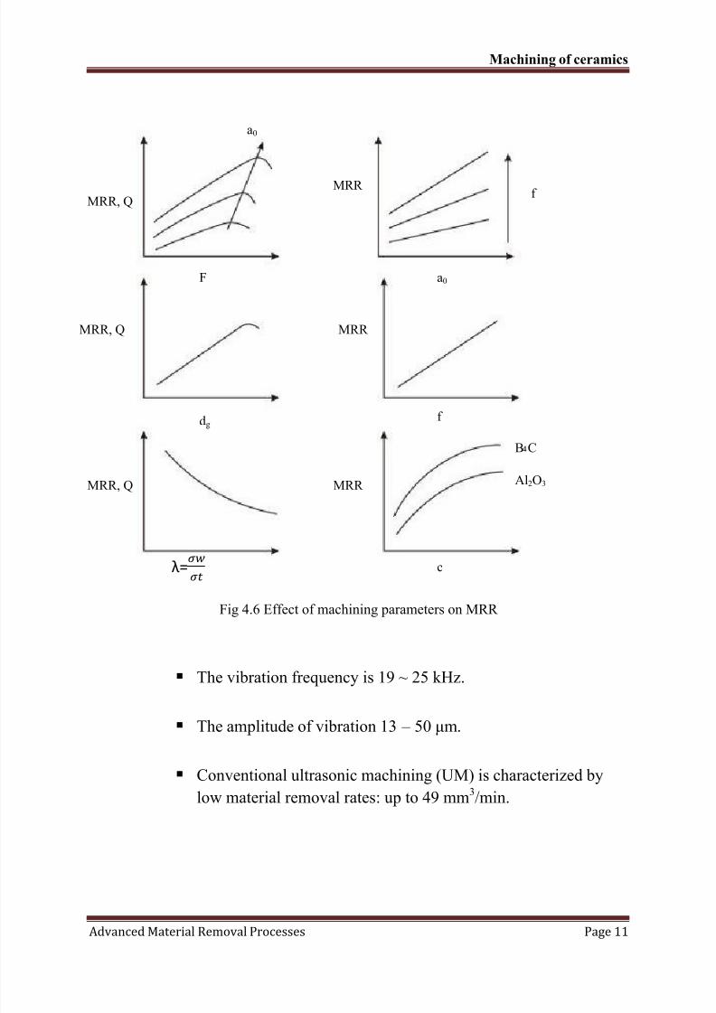
Fig 4.6 Effect of machining parameters on MRR
The vibration frequency is 19 ~ 25 kHz.
The amplitude of vibration 13 – 50 μm.
Conventional ultrasonic machining (UM) is characterized by
low material removal rates: up to 49 mm3/min.
MRR, Q
F
a0
fMRR
a0
MRR, Q
dgf
MRR
MRR, Q MRR
B C
Al2O3
cλ=
8/10/2019 Chapter 4-Machining of Ceramics
http://slidepdf.com/reader/full/chapter-4-machining-of-ceramics 12/26
Machining of ceramics
Advanced Material Removal Processes Page 12
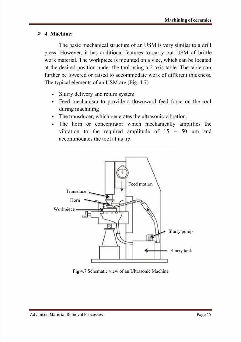
4. Machine:
The basic mechanical structure of an USM is very similar to a drill
press. However, it has additional features to carry out USM of brittle
work material. The workpiece is mounted on a vice, which can be locatedat the desired position under the tool using a 2 axis table. The table can
further be lowered or raised to accommodate work of different thickness.
The typical elements of an USM are (Fig. 4.7)
• Slurry delivery and return system
• Feed mechanism to provide a downward feed force on the tool
during machining
• The transducer, which generates the ultrasonic vibration.
• The horn or concentrator which mechanically amplifies the
vibration to the required amplitude of 15 – 50 μm and
accommodates the tool at its tip.
Fig 4.7 Schematic view of an Ultrasonic Machine
Feed motion
Transducer
Horn
Workpiece
Slurry pump
Slurry tank
8/10/2019 Chapter 4-Machining of Ceramics
http://slidepdf.com/reader/full/chapter-4-machining-of-ceramics 13/26
Machining of ceramics
Advanced Material Removal Processes Page 13
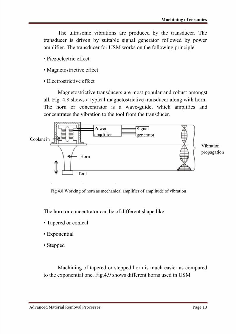
The ultrasonic vibrations are produced by the transducer. The
transducer is driven by suitable signal generator followed by power
amplifier. The transducer for USM works on the following principle
• Piezoelectric effect
• Magnetostrictive effect
• Electrostrictive effect
Magnetostrictive transducers are most popular and robust amongst
all. Fig. 4.8 shows a typical magnetostrictive transducer along with horn.
The horn or concentrator is a wave-guide, which amplifies and
concentrates the vibration to the tool from the transducer.
Fig 4.8 Working of horn as mechanical amplifier of amplitude of vibration
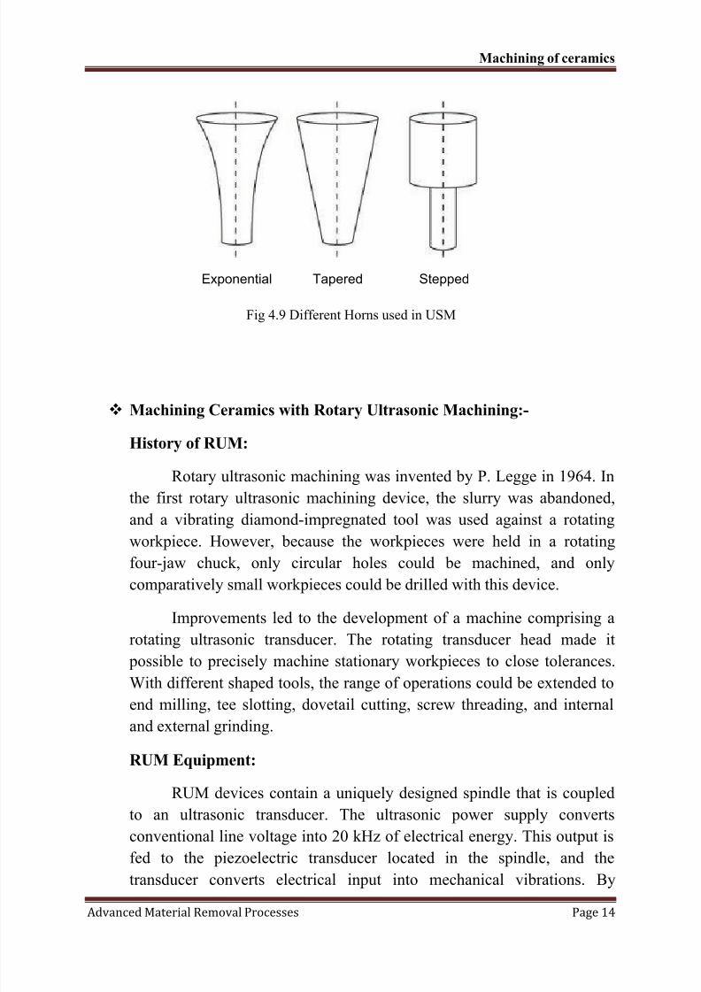
The horn or concentrator can be of different shape like
• Tapered or conical
• Exponential
• Stepped
Machining of tapered or stepped horn is much easier as compared
to the exponential one. Fig.4.9 shows different horns used in USM
Coolant in
Power
am lifier
Signal
generator
Horn
Tool
Vibration
propagation
8/10/2019 Chapter 4-Machining of Ceramics
http://slidepdf.com/reader/full/chapter-4-machining-of-ceramics 14/26
Machining of ceramics
Advanced Material Removal Processes Page 14
Exponential Tapered Stepped
Fig 4.9 Different Horns used in USM
Machining Ceramics with Rotary Ultrasonic Machining:-
History of RUM:
Rotary ultrasonic machining was invented by P. Legge in 1964. In
the first rotary ultrasonic machining device, the slurry was abandoned,
and a vibrating diamond-impregnated tool was used against a rotatingworkpiece. However, because the workpieces were held in a rotating
four-jaw chuck, only circular holes could be machined, and only
comparatively small workpieces could be drilled with this device.
Improvements led to the development of a machine comprising a
rotating ultrasonic transducer. The rotating transducer head made it
possible to precisely machine stationary workpieces to close tolerances.
With different shaped tools, the range of operations could be extended to
end milling, tee slotting, dovetail cutting, screw threading, and internal
and external grinding.
RUM Equipment:
RUM devices contain a uniquely designed spindle that is coupled
to an ultrasonic transducer. The ultrasonic power supply converts
conventional line voltage into 20 kHz of electrical energy. This output is
fed to the piezoelectric transducer located in the spindle, and the
transducer converts electrical input into mechanical vibrations. By
8/10/2019 Chapter 4-Machining of Ceramics
http://slidepdf.com/reader/full/chapter-4-machining-of-ceramics 15/26
Machining of ceramics
Advanced Material Removal Processes Page 15
changing the setting of the output control of the power supply, the
amplitude of the ultrasonic vibration can be adjusted. The spindle speed
(measured in revolutions per minute [rpm]) is programmable using the
CNC controller for speeds up to 8000 rpm.
A variety of tool shapes are used for rotary ultrasonic machining,
and ceramic and technical glass machining applications typically use
either a diamond-impregnated or electroplated tool. Diamond-
impregnated tools are more durable, but electroplated tools are less
expensive, so the selection depends on the particular application.
One of the major differences between USM and RUM equipment
is that USM uses a soft tool, such as stainless steel, brass or mild steel,
and slurry loaded with hard abrasive particles, while in RUM the hard
abrasive particles are diamond and are bonded on the tools. Another
major difference is that the RUM tool rotates and vibrates
simultaneously, while the USM tool only vibrates. These differences
enable RUM to provide both speed and accuracy advantages in ceramic
and glass machining operations.
Rotary ultrasonic machining provides a fast, high-quality
machining method for many ceramic and glass applications. Rotary
ultrasonic machining (RUM) is a hybrid machining process that combines
the material removal mechanisms of diamond grinding with ultrasonic
machining (USM), resulting in higher material removal rates (MRR) than
those obtained by either diamond grinding or USM alone. Experiments
with calcium aluminium silicate and magnesia-stabilized zirconia have
shown that the MRR obtained with RUM is six to 10 times higher than
that of a conventional grinding process under similar conditions, and it is
about 10 times faster than USM. It is also easier to drill deep holes with
RUM than with USM, and the hole accuracy is improved. Other
advantages of this process include a superior surface finish and low tool
pressure.
8/10/2019 Chapter 4-Machining of Ceramics
http://slidepdf.com/reader/full/chapter-4-machining-of-ceramics 16/26
Machining of ceramics
Advanced Material Removal Processes Page 16
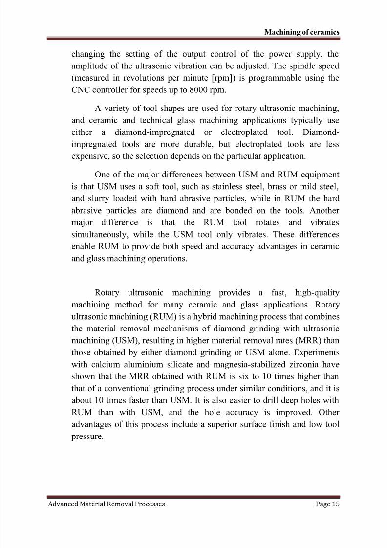
Figure-4.10: In ultrasonic machining, the tool, which is shaped conversely to the desired hole
or cavity, oscillates at high frequency, typically 20 kHz, and is fed into the workpiece by a
constant force.
In ultrasonic machining, the tool, shaped conversely to the
desired hole or cavity, oscillates at high frequency, typically 20kHz, and is fed into the workpiece by a constant force (see
Figure 4.10). Abrasive slurry composed of water and small
abrasive particles is supplied between the tool tip and the
workpiece. Material removal occurs when the abrasive particles,
suspended in the slurry between the tool and workpiece, impact
the workpiece due to the down stroke of the vibrating tool.
8/10/2019 Chapter 4-Machining of Ceramics
http://slidepdf.com/reader/full/chapter-4-machining-of-ceramics 17/26
Machining of ceramics
Advanced Material Removal Processes Page 17
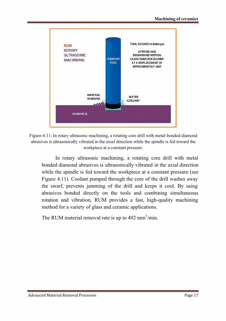
Figure-4.11: In rotary ultrasonic machining, a rotating core drill with metal-bonded diamond
abrasives is ultrasonically vibrated in the axial direction while the spindle is fed toward the
workpiece at a constant pressure.
In rotary ultrasonic machining, a rotating core drill with metal
bonded diamond abrasives is ultrasonically vibrated in the axial direction
while the spindle is fed toward the workpiece at a constant pressure (see
Figure 4.11). Coolant pumped through the core of the drill washes away
the swarf, prevents jamming of the drill and keeps it cool. By using
abrasives bonded directly on the tools and combining simultaneous
rotation and vibration, RUM provides a fast, high-quality machining
method for a variety of glass and ceramic applications.
The RUM material removal rate is up to 492 mm3/min.
8/10/2019 Chapter 4-Machining of Ceramics
http://slidepdf.com/reader/full/chapter-4-machining-of-ceramics 18/26
Machining of ceramics
Advanced Material Removal Processes Page 18
5. Applications of Ultrasonic machining:
1. Machining of cavities in electrically non-conductive ceramics.
2. Used to machine fragile components in which otherwise the scrap rate is
high.3. Used for multistep processing for fabricating silicon nitride (Si3N4)
turbine blades.
4. Large number of holes of small diameter. 930 holes with 0.32mm has
been reported (Benedict, 1973) using hypodermic needle.
5. Used for machining hard, brittle metallic-alloys, semiconductors, glass,
ceramics, carbides etc.
6. Used for machining round, square, irregular shaped holes and surface
impressions.7. Used in machining of dies for wire drawing, punching and blanking
operations.
8. USM can perform machining operations like drilling, grinding and
milling operations on all materials which can be treated suitably with
abrasives.
9. USM has been used for piercing of dies and for parting off and blanking
operations.
10. USM enables a dentist to drill a hole of any shape on teeth without any pain.
11. Ferrites and steel parts, precision mineral stones can be machined using
USM.
12. USM can be used to cut industrial diamonds.
13. USM is used for grinding Quartz, Glass, and ceramics.
14. Cutting holes with curved or spiral centre lines and cutting threads in
glass and mineral or metallo-ceramics.
6. Advantages of ultrasonic machining include:
1. The process is non-thermal, non-chemical, and non-electrical, leaving the
chemical and physical properties of the workpiece unchanged. This low-
stress process translates into high reliability for your critical applications.
2. Multiple features can be machined at the wafer or substrate level
simultaneously, and the process is scalable. Our process is often the
highest quality and lowest cost solution.
8/10/2019 Chapter 4-Machining of Ceramics
http://slidepdf.com/reader/full/chapter-4-machining-of-ceramics 19/26
Machining of ceramics
Advanced Material Removal Processes Page 19
3. Ultrasonic machined features have vertical side walls, enabling you to
preserve valuable space for your designs that translate into higher
productivity.
4. The process integrates well with semiconductor and MEMS processes.
Machined features can be aligned to previously patterned, machined, or
etched substrates.
Grinding of ceramics:
Grinding is used in machining of Ceramics in the sintered state.
Grinding operation involves a rotating abrasive wheel removing thematerial from the surface of the workpiece.
The grinding zone is continuously flushed with a fluid coolant,
which cools the grinding zone, lubricates the contact between the wheel
and the part surfaces, removes the micro-chips (debris) produced in the
grinding process.
Resin-bond wheels with either synthetic or natural diamond of
different grit size pressed at different concentrations in polymer (resin)
matrices are commonly used for grinding ceramics.
Electrolytic in-process dressing (ELID) technique of dressing
metal-bonded grinding wheels is used for fine (Nano) finishes grinding.
The Material Removal Rate (MRR) of grinding ceramics is
maximum 9.832 mm3/min.
Laser assisted machining of ceramics:
Laser assisted machining (LAM) is the method of machining
ceramics using a laser beam directed to the workpiece area located
directly in front of the conventional cutting tool.
The laser beam heats and softens (not melts) the ceramic material
at the surface just prior the cutting action.
8/10/2019 Chapter 4-Machining of Ceramics
http://slidepdf.com/reader/full/chapter-4-machining-of-ceramics 20/26
Machining of ceramics
Advanced Material Removal Processes Page 20
As a result the cut material becomes ductile and it may be removed
much faster than in conventional cutting operation without laser
assistance. The LAM material removal rate is up to 983 mm3/min.
Titanium nitride coated tools are used for the laser assisted
machining of ceramics.
Traditional machining operations (milling, turning) may be
performed by the method of the laser assisted machining.
Laser machining of ceramics
Laser machining of ceramics is the machining operation
performed by a high power laser melting the material, which is blown
away by a supersonic gas jet. The laser energy density required for
melting alumina ranges from 750 J/cm2 to 1000 J/cm
2.
The following machining operation may be performed by laser:
Drilling
Cutting
Scribing and marking
Residual stresses and micro-cracks may form at the cut edge as a
result of the shrinkage of the solidified molten material.
Preheating of the ceramic workpiece to 2550ºF (1399ºC) prior to the laser
machining allows to minimize micro-cracking due to reduction of the
temperature gradients and thermal stresses.
8/10/2019 Chapter 4-Machining of Ceramics
http://slidepdf.com/reader/full/chapter-4-machining-of-ceramics 21/26
Machining of ceramics
Advanced Material Removal Processes Page 21
A note on Fabrication of ceramics:
Sintering:
Sintering is a method for creating objects from powders, including metal and ceramic powders. It is based on atomic diffusion.
Diffusion occurs in any material above absolute zero, but it occurs much
faster at higher temperatures. In most sintering processes, the powdered
material is held in a mould and then heated to a temperature below the
melting point. The atoms in the powder particles diffuse across the
boundaries of the particles, fusing the particles together and creating one
solid piece. Because the sintering temperature does not have to reach the
melting point of the material, sintering is often chosen as the shaping process for materials with extremely high melting points such as
tungsten and molybdenum.
Sintering is traditionally used for manufacturing ceramic objects
but finds applications in almost all fields of industry. The study of
sintering and of powder-related processes is known as powder
metallurgy. A simple, intuitive example of sintering can be observed
when ice cubes in a glass of water adhere to each other.
In certain moulding processes a relatively large amount of
temporary organic binder is used, which needs to be burnt out in a
separate step. Sintering is then carried out in air. We have furnaces for
sintering in air up to 1800°C, or inert graphite furnaces with a maximum
temperature of 2300°C.
Ceramic sintering:
Sintering is part of the firing process used in the manufacture of
pottery and other ceramic objects. These objects are made from
substances such as glass, alumina, zirconia, silica, magnesia, lime,
beryllium oxide and ferric oxide. Some ceramic raw materials have a
lower affinity for water and a lower plasticity index than clay, requiring
organic additives in the stages before sintering. The general procedure of
creating ceramic objects via sintering of powders includes:
Mixing water, binder, deflocculant, and unfired ceramic powder toform a slurry;
8/10/2019 Chapter 4-Machining of Ceramics
http://slidepdf.com/reader/full/chapter-4-machining-of-ceramics 22/26
Machining of ceramics
Advanced Material Removal Processes Page 22
Spray-drying the slurry;
Putting the spray dried powder into a mould and pressing it to form a
green body (an unsintered ceramic item);
Heating the green body at low temperature to burn off the binder; Sintering at a high temperature to fuse the ceramic particles together.
All the characteristic temperatures associated to phase
transformation, glass transitions and melting points, occurring during a
sinterisation cycle of a particular ceramics formulation (i.e., tails and
frits) can be easily obtained by observing the expansion-temperature
curves during optical dilatometer thermal analysis. In fact, sinterisation
is associated to a remarkable shrinkage of the material because glass
phases flow, once their transition temperature is reached, and start
consolidating the powdery structure and considerably reducing the
porosity of the material.
There are two types of sintering: with pressure (also known as hot
pressing), and without pressure. Pressure less sintering is possible with
graded metal-ceramic composites, with a nanoparticle sintering aid and
bulk moulding technology. A variant used for 3D shapes is called hot
isostatic pressing.
To allow efficient stacking of product in the furnace during
sintering and prevent parts sticking together, many manufacturers
separate ware using Ceramic Powder Separator Sheets. These sheets
are available in various materials such as alumina, zirconia and magnesia.
They are additionally categorized by fine, medium and coarse particle
sizes. By matching the material and particle size to the ware being
sintered, surface damage and contamination can be reduced while
maximizing furnace loading.
Hot isostatic pressing:-
Hot isostatic pressing (HIP) is a manufacturing process used to
reduce the porosity of metals and increase the density of many ceramic
materials. This improves the material's mechanical properties and
workability.
The HIP process subjects a component to both elevatedtemperature and isostatic gas pressure in a high pressure containment
8/10/2019 Chapter 4-Machining of Ceramics
http://slidepdf.com/reader/full/chapter-4-machining-of-ceramics 23/26
Machining of ceramics
Advanced Material Removal Processes Page 23
vessel. The pressurizing gas most widely used is argon. An inert gas is
used, so that the material does not chemically react. The chamber is
heated, causing the pressure inside the vessel to increase. Many systems
use associated gas pumping to achieve the necessary pressure level.
Pressure is applied to the material from all directions (hence the term
"isostatic").
For processing castings, metal powders can also be turned to
compact solids by this method; the inert gas is applied between 50.7 MPa
and 310 MPa, with 100 MPa being most common. Process soak
temperatures range from 482 °C for aluminium castings to 1,320 °C for
nickel- based superalloys. When castings are treated with HIP, the
simultaneous application of heat and pressure eliminates internal voidsand micro-porosity through a combination of plastic deformation,
creep, and diffusion bonding; this process improves fatigue resistance of
the component. Primary applications are the reduction of micro-
shrinkage, the consolidation of powder metals, ceramic composites and
metal cladding. Hot isostatic pressing is also used as part of a sintering
(powder metallurgy) process and for fabrication of metal matrix
composites.
Enhanced product properties:-
The ability to manufacture HIP products with irregular shapes and
complex geometry offers several advantages over castings, forgings and
fabricated materials, both in terms of design flexibility and material
properties.
The fine microstructure and isostatic pressure with which the HIP
products are processed result in isotropic mechanical properties, in other
words, properties that are equal in all directions. The isotropic properties
can contribute to, for example, lighter constructions.
Main advantages with products produced by hot isostatic pressing:
Increased design flexibility
Reduction of costly operations like machining and welding
Improved process safety Enhanced material properties
8/10/2019 Chapter 4-Machining of Ceramics
http://slidepdf.com/reader/full/chapter-4-machining-of-ceramics 24/26
Machining of ceramics
Advanced Material Removal Processes Page 24
HIP Applications:-
Aerospace Casting Densification:
HIP is used to remove porosity from a wide range of nickel-based
super alloy and titanium precision castings for aircraft engines and
structural components.
Biomedical Casting Densification:
HIP is used in the medical industry to improve the properties of
cast cobalt chrome, titanium and stainless steel implants.
Industrial Casting Densification:
Industrial applications for hot isostatic pressing cover a wide range
of industries and products such as electrical and electronic casings,
machine tools and pump impellers.
Power Generation Casting Densification:
In the power generation industry, hot isostatic pressing is used to
densify turbine blades, shafts, discs and other components to remove
porosity and enhance performance.
Powder Metallurgy:
Powder metal consolidation via HIP is used to produce near net
shape components faster, with reduced weight and less machining than
traditional castings and forgings.
Cladding & Diffusion Bonding:
HIP is used in a range of applications to clad, weld and join
dissimilar materials.
8/10/2019 Chapter 4-Machining of Ceramics
http://slidepdf.com/reader/full/chapter-4-machining-of-ceramics 25/26
Machining of ceramics
Advanced Material Removal Processes Page 25
Finishing Process:
Ceramic glaze:
Glaze is a layer or coating of a vitreous substance which has beenfused to a ceramic object through firing. Glaze can serve to color,
decorate, strengthen or waterproof an item.
Use:-
Glazing is important for earthenware vessels as otherwise they
would be unsuitable for holding liquids due to porosity. Glaze is also
used on stoneware and porcelain. In addition to the functional aspect of
glazes, they can form a variety of surface finishes, including degrees ofgloss and matte and color. Glazes may also enhance an underlying design
or texture which may be either the unmodified texture of the underlying
body, or an inscribed, carved or painted design.
Glaze is used on building materials. The Iron Pagoda, built in
1049 in Kaifeng, China, of glazed bricks is an example.
Composition:-
Ceramic glaze raw materials generally include silica, which will be
the main glass former. Various metal oxides, such as sodium, potassium
and calcium, act as a flux to lower the melting temperature. Alumina,
often derived from clay, stiffens the molten glaze to prevent it from
running off the piece. Colorants, such as iron oxide, copper carbonate
or cobalt carbonate, and sometimes opacifiers such as tin oxide or
zirconium oxide, are used to modify the visual appearance of the fired
glaze.
Process:-
Glaze may be applied by dry dusting a dry mixture over the surface
of the clay body or by inserting salt or soda into the kiln at high
temperatures to create an atmosphere rich in sodium vapor that interacts
with the aluminium and silica oxides in the body to form and deposit
glass, producing what is known as salt glaze pottery. Most commonly,
glazes in aqueous suspension of various powdered minerals and metaloxides are applied by dipping pieces directly into the glaze. Other
8/10/2019 Chapter 4-Machining of Ceramics
http://slidepdf.com/reader/full/chapter-4-machining-of-ceramics 26/26
Machining of ceramics
d d l l
techniques include pouring the glaze over the piece, spraying it onto the
piece with an airbrush or similar tool, or applying it directly with a brush
or other tool.
To prevent the glazed article from sticking to the kiln during firingeither a small part of the item is left unglazed or supported on small
refractory supports called kiln spurs which are removed and discarded
after the firing. Small marks left by these spurs are sometimes visible on
finished ware.
Decoration applied under the glaze on pottery is generally referred
to as underglaze. Underglazes are applied to the surface of the pottery,
which can be either raw, "greenware", or "biscuit" fired (an initial firing
of some articles before the glazing and re-firing). A wet glaze — usually
transparent — is applied over the decoration. The pigment fuses with the
glaze, and appears to be underneath a layer of clear glaze. An example of
underglaze decoration is the well-known "blue and white" porcelain
famously produced in England, The Netherlands, China and Japan.
The striking blue color is achieved by using cobalt in the form of either
cobalt oxide or cobalt carbonate, both of which are still commonly used.
Decoration applied on top of a layer of glaze is referred to asoverglaze. Overglaze methods include applying one or more layers or
coats of glaze on a piece of pottery or by applying a non-glaze substance
such as enamel or metals (i.e., gold leaf ) over the glaze.
Overglaze colours are low-temperature glazes that give ceramics a
more decorative, glassy look. A piece is fired first, overglaze is applied,
and it is fired again. Once the piece is fired and comes out of the kiln, its
texture becomes smoother because of the glaze.