chapter 4: network layer - École polytechnique …ica layer to get the segment to the destination...
TRANSCRIPT

1
4: Network Layer 4-1
Chapter 4: Network Layer
Silvia Giordano
ICA, EPFL
The transport layer relies on the services of the network layer, which provides a communication service between hosts. In particular, the network layer moves transport- layer segments from one host to another. At the sending host, the transport- layer segment is passed to the network layer. It is then the job of the network layer to get the segment to the destination host and pass the segment up the protocol stack to the transport layer.

2
4: Network Layer 4-2
Network LayerChapter goals:r understand principles
behind network layer services:m routing m how a router worksm advanced topics: IPv6,
multicastr instantiation and
implementation in the Internet
Overview:r network layer servicesr routing principlesr IP addressesr Internet routing protocols
reliable transferm intra-domainm inter-domain
r ICMPr Routers, bridges and switchesr IPv6r multicast routing

3
4: Network Layer 4-3
Network layer functions
r transport packet from sending to receiving hosts
r network layer protocols in every host, router
three important functions:r path determination: route
taken by packets from source to dest. Routing algorithms
r switching: move packets from router’s input to appropriate router output
r call setup: some network architectures require router call setup along path before data flows
networkdata linkphysical
networkdata linkphysical
networkdata linkphysical
networkdata linkphysical
networkdata linkphysical
networkdata linkphysical
networkdata linkphysical
networkdata linkphysical
applicationtransportnetworkdata linkphysical
applicationtransportnetworkdata linkphysical
The network layer involves each and every host and router in the network. The role of the network layer in a sending host is to begin the packet on its journey to the receiving host. The role of the network layer is thus deceptively simple--to transport packets from a sending host to a receiving host. To do so, three important network- layer functions can be identified:
•Path determination. The network layer must determine the route or path taken by packets as they flow from a sender to a receiver. The algorithms that calculate these paths are referred to as routing algorithms.
•Switching. When a packet arrives at the input to a router, the router mustmove it to the appropriate output link.
•Call setup. With TCP, a three-way handshake is required before data actually flow from sender to receiver. This allowed the sender and receiver to set up the needed state information (for example, sequence number and initial flow-control window size). In an analogous manner, some network- layer architectures (for example, ATM) require that the routers along the chosen path from source to destination handshake with each other in order to setupstate before data actually begins to flow. In the network layer, this process is referred to as call setup. The network layer of the Internet architecture does not perform any such call setup.

4
4: Network Layer 4-4
Network service model
rThe network service model defines edge-to-edge channel
rThe most important abstraction provided by network layer: m network-layer connection-oriented
service: virtual circuitm network-layer connectionless service:
datagram
The network-service model defines the characteristics of end-to-end transport of data between one "edge" of the network and the other, that is, between sending and receiving end systems. The most important abstraction that the network layer provides to the transport layer is whether the network layer uses a connection-oriented service (virtual circuits) or a connectionless service(datagram) model.
With a virtual circuits layer a circuit management (setup, data-transfer, teardown) and signaling are needed.
With a datagram network layer, each time an end system wants to send a packet, it stamps the packet with the address of the destination end system, and then pops the packet into the network

5
4: Network Layer 4-5
Virtual circuits
r call setup, teardown for each call before data can flowr each packet carries VC identifier (not destination host ID)r every router on source-dest path maintains “state” for
each passing connectionm transport-layer connection only involved two end systems
r link, router resources (bandwidth, buffers) may be allocated to VCm to get circuit-like performance
“source-to-dest path behaves much like telephone circuit”m performance-wisem network actions along source-to-dest path
There are three identifiable phases in a virtual circuit:
•VC setup. During the setup phase, the sender contacts the network layer, specifies the receiver address, and waits for the network to set up the VC. The network layer determines the path between sender and receiver, that is, the series of links and packet switches through which all packets of the VC will travel. This typically involves updating tables in each of the packet switches in the path. During VC setup, the network layer may also reserve resources (for example, bandwidth) along the path of the VC.
•Data transfer. Once the VC has been established, data can begin to flow along the VC. Each packet knows the VC (carries the VC identifier), and everyswitch on the VC path is aware of the existence of the VC itself.
•Virtual-circuit teardown. This is initiated when the sender (or receiver) informs the network layer of its desire to terminate the VC. The network layer will then typically inform the end system on the other side of the network of the call termination and update the tables in each of the packet switches on the path to indicate that the VC no longer exists.

6
4: Network Layer 4-6
Virtual circuits: signaling protocols
r used to setup, maintain teardown VCr used in ATM, frame-relay, X.25r not used in today’s Internet (at network layer)
applicationtransportnetworkdata linkphysical
applicationtransportnetworkdata linkphysical
1. Initiate call 2. incoming call3. Accept call4. Call connected
5. Data flow begins 6. Receive data
The messages that the end systems send to the network to indicate the initiation or termination of a VC, and the messages passed between the switches to set up the VC (that is, to modify switch tables) are known as signaling messages and the protocols used to exchange these messages are often referred to as signaling protocols. In the Internet virtual circuits is not used at network layer, while ATM, frame relay and X.25, are three other networking technologies that use virtual circuit.

7
4: Network Layer 4-7
Datagram networks: the Internet model
r no call setup at network layerr routers: no state about end-to-end connections
m no network-level concept of “connection”r packets typically routed using destination host ID
m packets between same source-dest pair may take different paths
applicationtransportnetworkdata linkphysical
applicationtransportnetworkdata linkphysical
1. Send data 2. Receive data
Datagram routing is similar to routing ordinary postal mail: packet switches route a packet toward its destination by examining the packet's destination address, indexing a routing table with the destination address, and forwarding the packet in the direction of the destination. There is no “connection management” as well as no tables or state are needed insiede the network. Different packets to the same destination can be routed via a different route. The current Internet architecture provides only one service model, thedatagram service, which is also known as "best-effort service." From the table, it might appear that best effort service is a euphemism for "no service at all." With best-effort service, timing between packets is not guaranteed to be preserved, packets are not guaranteed to be received in the order in which they were sent, nor is the eventual delivery of transmitted packets guaranteed. Given this definition, a network that delivered no packets to the destination would satisfy the definition of best-effort delivery service. However, there are sound reasons for such a minimalist network service model:
•it is easier to interconnect networks that used very different link- layer technologies
•it is easier to add a new service simply by attaching a host to the network and defining a new higher- layer protocol
The Internet's best-effort only service model is currently being extended to include so-called integrated services and differentiated service.

8
4: Network Layer 4-8
The Internet Network layer
routingtable
Host, router network layer functions:
Routing protocols•path selection•RIP, OSPF, BGP
IP protocol•addressing conventions•datagram format•packet handling conventions
ICMP protocol•error reporting•router “signaling”
Transport layer: TCP, UDP
Link layer
physical layer
Networklayer
The pieces of the network layer of the Internet are often collectively referred toas the IP layer (named after the Internet's IP protocol). We'll see, though, that the IP protocol itself is just one piece (albeit a very important piece) of the Internet's network layer. The Internet's network layer provides connectionlessdatagram service rather than virtual-circuit service. When the network layer at the sending host receives a segment from the transport layer, it encapsulates the segment within an IP datagram, writes the destination host address as well as other fields in the datagram, and sends the datagram to the first router on the path toward the destination host. The Internet’s network layer has three major components:
•The Internet Protocol, or more commonly, the IP Protocol, which defines network- layer addressing, the fields in the datagram (that is, the network- layer PDU), and the actions taken by routers and end systems on a datagram based on the values in these fields. There are two versions of the IP protocol in use today: IPv4 [RFC 791] and IPv6 [RFC 2373; RFC 2460], which has been proposed to replace IPv4 in upcoming years.
•The second major component of the network layer is the path determination component; it determines the route a datagram follows from source to destination. Examples of such components used in the Internet are RIP, OSPF, BGP.
•The Internet's network- layer error and information reporting protocol, ICMP, is a facility to report errors in datagrams and respond to requests for certain network- layer information..

9
- an internet can use its own addresses
- Internet addresses are managed worldwide
There is no global Internet organization: like for telephony, the Internets ervcie is provided by a collection of competing Internet Service Providers (ISPs)
Only addresses and standards are managed world-wide.
4: Network Layer 4-9
Internet and intranetr an intranet
a collection of end and intermediate systems interconnected using the TCP/IP architecturenormally inside one organization
r the Internetthe global collection of all hosts and routers interconnected using the TCP/IP architecturecoordinated allocation of addresses and implementation requirements by the Internet Society
r intranets are often connected to the Internet by firewallsm hosts that act as application level relays

10
4: Network Layer 4-10
IP Addressing: introductionr IP address: 32-bit
identifier for host, router interface
r interface: connection between host, router and physical linkm router’s typically have
multiple interfacesm host may have multiple
interfacesm IP addresses
associated with interface, not host, router
128.178.1.1
128.178.1.2
128.178.1.3
128.178.1.4 128.178.2.9
128.178.2.2
128.178.2.1
128.178.3.2128.178.3.1
128.178.3.27
128.1.1.1 = 10000000 00000001 00000001 00000001
128 1 11
32 bits
interface1 interface2
interface3
An IP address is technically associated with an interface, rather than with the host or router containing that interface When IP in the host wants to send adatagram, it will do so over this link. The boundary between the host and the physical link is called an interface. A router's job is to receive a datagram on an "incoming" link and forward the datagram on some "outgoing" link, thus a router has multiple interfaces, one for each of its links.
Each IP address is 32 bits long (equivalently, four bytes), and there are thus a total of 232 possible IP addresses. These addresses are typically written in so-called dotted-decimal notation, in which each byte of the address is written in its decimal form and is separated by a period ("dot") from other bytes in the address. For example, consider the IP address 193.32.216.9. The 193 is the decimal equivalent of the first eight bits of the address; the 32 is the decimal equivalent of the second eight bits of the address, and so on. Thus, the address 193.32.216.9 in binary notation is:
11000001 00100000 11011000 00001001.
Each interface on every host and router in the global Internet must have an IP address that is globally unique.

11
4: Network Layer 4-11
IP Addressingr IP address:
m network (or prefix) part (high order bits)
m host part (low order bits)
r What’s a network ? (from IP address perspective)m device interfaces with
same network part of IP address
m can physically reach each other without intervening router
128.178.1.1
128.178.1.2
128.178.1.3
128.178.1.4128.178.2.9
128.178.2.2
128.178.2.1
128.178.3.2128.178.3.1
128.178.3.27
network consisting of 3 IP networks(for IP addresses starting with 128, first 24 bits are network address)
LAN 128.178.3
Network 128.178.0.0
IP addresses cannot be chosen in a willy-nilly manner, however. In primis, an interface's IP address will be determined by the "network" to which it is connected. The three hosts in the upper- left portion are on the same “IP network” identified by the initial part of their address 128.178.1, and the router interface to which they are connected all have an IP address of the form 128.178.1.xxx. That is, they share a common leftmost 24 bits of their IP address. The 24 address bits that they share in common constitute the network portion of their IP address; the remaining eight bits are the host portion of the IP address. The network itself also has an address: 128.178.1.0/24, where the "/24" notation, sometimes known as a network mask, indicates that the leftmost 24 bits of the 32-bit quantity define the network Sometimes, in the network mask the numbers are substituted with 255. Examples:
subnet mask at EPFL = 255.255.255.0
What are the net:subnet and host parts of : lrcsuns .lrc.epfl.ch ? The address is 128.178.156.24
the prefix is 128.178.156.0

12
4: Network Layer 4-12
Network Example with IP Addresses 129.132
66.46
129.132.100.12
lrcsuns128.178.156.24
08:00:20:71:0D:D4
lrcpc3128.178.156.7
00:00:C0:B8:C2:8D
in-inr128.178.156.1
00:00:0C:02:78:36128.178.79.1
00:00:0C:17:32:96
ed2-in182.1 in-inj
128.178.182.3182.5
128.178.100.3
LRC
15.221
Anneau SIDI SUN
DI
ed0-swi15.13 128.178.100.12
128.178.84.1ed0-ext EPFL-Backbone
sic500cs128.178.84.130
Modem+ PPP
disun3128.178.79.9
08:00:20:20:46:2E
128.178.84.133
stisun1 15.7
128.178.47.5128.178.47.3
Switch
ezci7-ethz- switch129.132.35.1
130.59.x.x
ed2-el
128.178.29.6408:00:07:01:a2:a5
LEMA
128.178.156.2308:00:07:01:a2:a5
ezci7-ethz- switch
KomsysETHZ-Backbone
129.132.100.27
lrcmac4
lrcmac4
13
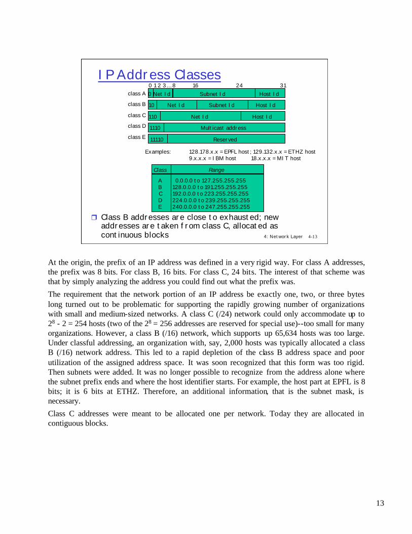
At the origin, the prefix of an IP address was defined in a very rigid way. For class A addresses, the prefix was 8 bits. For class B, 16 bits. For class C, 24 bits. The interest of that scheme was that by simply analyzing the address you could find out what the prefix was.
The requirement that the network portion of an IP address be exactly one, two, or three bytes long turned out to be problematic for supporting the rapidly growing number of organizations with small and medium-sized networks. A class C (/24) network could only accommodate up to 28 - 2 = 254 hosts (two of the 28 = 256 addresses are reserved for special use)--too small for many organizations. However, a class B (/16) network, which supports up 65,634 hosts was too large. Under classful addressing, an organization with, say, 2,000 hosts was typically allocated a class B (/16) network address. This led to a rapid depletion of the class B address space and poor utilization of the assigned address space. It was soon recognized that this form was too rigid. Then subnets were added. It was no longer possible to recognize from the address alone where the subnet prefix ends and where the host identifier starts. For example, the host part at EPFL is 8 bits; it is 6 bits at ETHZ. Therefore, an additional information, that is the subnet mask, is necessary.
Class C addresses were meant to be allocated one per network. Today they are allocated in contiguous blocks.
4: Network Layer 4-13
IP Address Classes
Examples: 128.178.x.x = EPFL host; 129.132.x.x = ETHZ host9.x.x.x = IBM host 18.x.x.x = MIT host
Class Range
ABCDE
0.0.0.0 to 127.255.255.255128.0.0.0 to 191.255.255.255192.0.0.0 to 223.255.255.255224.0.0.0 to 239.255.255.255240.0.0.0 to 247.255.255.255
r Class B addresses are close to exhausted; new addresses are taken from class C, allocated as continuous blocks
0 Net Id0 1 2 3… 8 16 24 31
10 Net Id
110 Net Id
1110 Multicast address
11110 Reserved
Subnet Id
Host Id
Host Id
class A
class B
class C
class D
class E
Host Id
Subnet Id

14
With so-called CIDRized (CIDR: Classless Interdomain Routing) network addresses, the network part of an IP address can be any number of bits long, rather than being constrained to 8, 16, or 24 bits. A CIDRized network address has the dotted-decimal form a.b.c.d/x, where xindicates the number of leading bits in the 32-bit quantity that constitutes the network portion of the address. In our example above, the organization needing to support 2,000 hosts could be allocated a block of only 2,048 host addresses of the form a.b.c.d/21, allowing the approximately 63,000 addresses that would have been allocated and unused under classful addressing to be allocated to a different organization. In this case, the first 21 bits specify the organization's network address and are common in the IP addresses of all hosts in the organization. The remaining 11 bits then identify the specific hosts in the organization. In practice, the organization could further divide these 11 rightmost bits using a procedure known as subnetting to create its own internal networks within the a.b.c.d/21 network.
4: Network Layer 4-14
CIDR: IP Address Hierarchiesr The prefix of an IP address is itself structured in order
to support aggregationm For example: 128.178.x.y represents an EPFL host
128.178.156 / 24 represents the LRC subnet at EPFL128.178 / 16 represents EPFL
m Used between routers by routing algorithmsm This way of doing is called classless and was first introduced in
inter domain routing under the name of CIDR (classlessinterdomain routing)
r Notation: 128.178.0.0/16 means : the prefix made of the 16 first bits of the string
r It is equivalent to: 128.178.0.0 with netmask=255.255.0.0r In the past, the class based addresses, with networks of
class A, B or C was used; now only the distinction between class D and non-class D is relevant.

15
4: Network Layer 4-15
IP Addresses (examples -1)r subnet mask at ETHZ = 255.255.255.192(that is 111111111.11111111.111111111.11000000)r CIDR 129.132.0.0/26r question: net:subnet and host parts of
spr13.tik.ee.ethz.ch = 129.132.119.77 ?answer: (77=01001101)
net:subnet = 129.132.119.64 (64=01000000)host = 13=001101 (6 bits)
net part host part6 bits

16
4: Network Layer 4-16
IP Addresses (examples -2)
r Sovkom has received IP addresses ___________ to ___________
r Java Business Solutions AG has received IP addresses ___________ to
___________r Tango SA
has received IP addresses ___________ to ___________
194.167.0.0/16
Internet Service Provider SovKom
Java Business Solutions AG
Tango SA
194.167.41.0/24
194.167.42.0/23
194.167. 255.255194.167.0.0
194.167.41.255194.167.41.0
194.167.42.0194.167.43.255
total: 216 addr., but .0 and .255 are not usable
total: 28 –2 addresses
total: 2*(28 –2) addresses
17
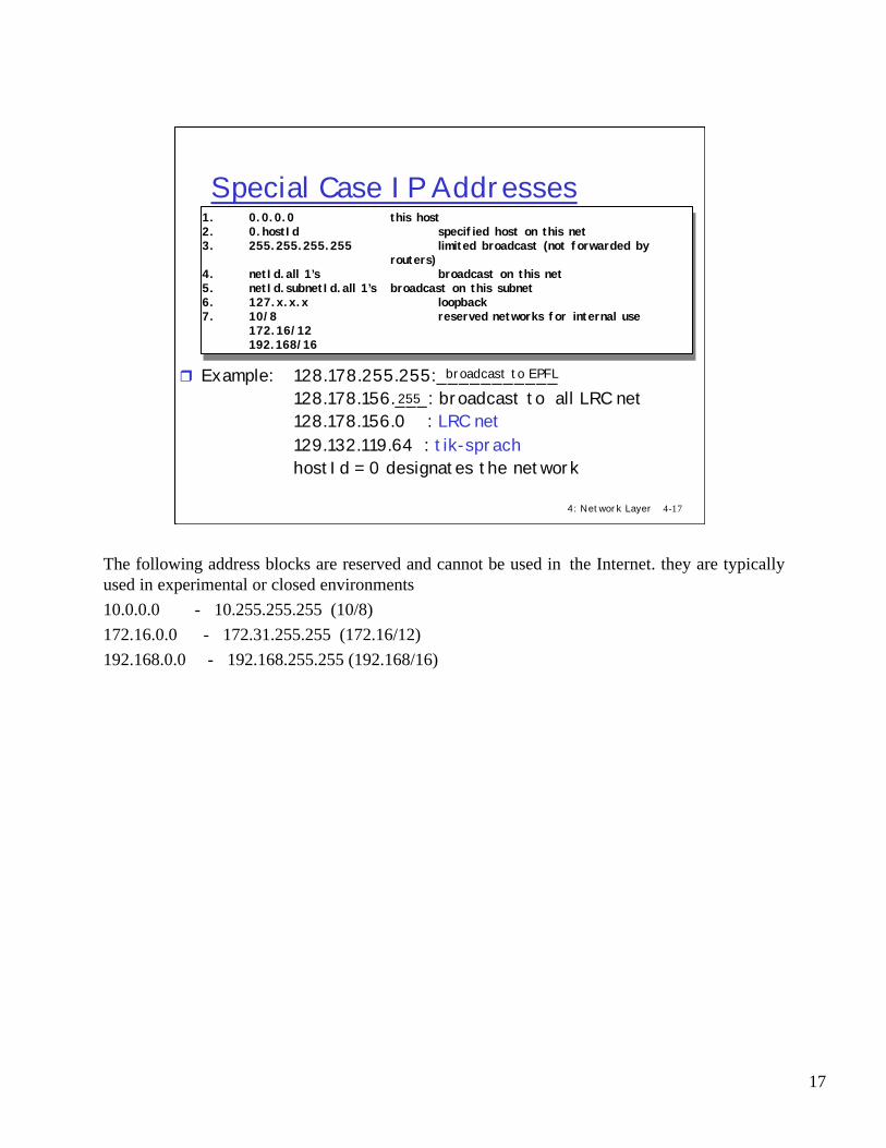
The following address blocks are reserved and cannot be used in the Internet. they are typically used in experimental or closed environments10.0.0.0 - 10.255.255.255 (10/8)172.16.0.0 - 172.31.255.255 (172.16/12)192.168.0.0 - 192.168.255.255 (192.168/16)
4: Network Layer 4-17
Special Case IP Addresses1. 0.0.0.0 this host2. 0.hostId specified host on this net3. 255.255.255.255 limited broadcast (not forwarded by
routers)4. netId.all 1’s broadcast on this net5. netId.subnetId.all 1’s broadcast on this subnet6. 127.x.x.x loopback7. 10/8 reserved networks for internal use
172.16/12 192.168/16
1. 0.0.0.0 this host2. 0.hostId specified host on this net3. 255.255.255.255 limited broadcast (not forwarded by
routers)4. netId.all 1’s broadcast on this net5. netId.subnetId.all 1’s broadcast on this subnet6. 127.x.x.x loopback7. 10/8 reserved networks for internal use
172.16/12 192.168/16
r Example: 128.178.255.255:___________128.178.156.___: broadcast to all LRC net128.178.156.0 : LRC net129.132.119.64 : tik-sprachhostId = 0 designates the network
broadcast to EPFL
255

18
We have seen the main principles of IP addressing: an IP address identifies an interface of an host (rather than the host itself); this address is unique in the Internet. In order to communicate, IP hosts needs to know the IP addresses. We can distinguish between routing inside a subnetwork and routing between subnetworks, where a subnetwork is a collection of hosts that can communicate directly without routers.
4: Network Layer 4-18
IP PrinciplesHomogeneous addressingr an IP address is unique across the whole network (
= the world in general)r IP address is the address of the interfacer communication between IP hosts requires
knowledge of IP addressesRouting:r inside a subnetwork: hosts communicate directly
without routersr between subnetworks: one or several routers are
usedr a subnetwork = a collection of systems with a
common prefix

19
The IP packet forwarding algorithm is the core of the TCP/IP architecture. It defines what a system should do with a packet it has to send or to forward. The rule is simple:
- if the destination IP address has the same prefix as one of self’s interfaces, send directly to that interface
- otherwise send to a router as given by the table
It uses the IP routing table; the table can be checked with a command such as “netstat” with Unix or “Route” with Windows NT
4: Network Layer 4-19
r Rule for sending packets (hosts, routers)m if the destination IP address has the same prefix as one of
self’s interfaces, send directly to that interfacem otherwise send to a router as given by the IP routing table
r Example of IP routing tables and Interface Tables:
The IP Packet Forwarding Algorithm
destination@ subnetMask nextHop
128.178.156.0DEFAULT
255.255.255.0128.178.156.1
At lrcsuns: Next Hop Table
IP subnetMask
128.178.156.24 255.255.255.0
Physical Interface Tables
destination@ subnetMask nextHop
128.178.79.0128.178.156.0
DEFAULT
255.255.255.0255.255.255.0 128.178.182.5
128.178.182.1
At in-inj: NextHop Table
IP subnetMask
128.178.182.3128.178.79.1
255.255.255.0255.255.255.0
Physical Interface Tables

20
In reality there are exceptions to the rule. The complete algorithm is as above; the cases should be test in that order (it is a nested if then else statement).
Remember that the above is the packet forwarding algorithm. The tables are written by the control method (the routing algorithms).
4: Network Layer 4-20
IP Unicast Packet Forwarding AlgorithmRead destAddr= destination IP address /* assume it is unicast */Case 1: a host route exists for destAddr
for every entry in routing table if(destinationaddr= destAddr) then send to nextHop IPaddr; leave
Case 2: destAddr is on a directly connected network (=on-link):for every physical interface IP address A and subnet mask smif(A & sm = destAddr & sm) then send directly to destAddr; leave
Case 3: a network route exists for destAddrfor every entry in routing table if(destinationaddr & subnetMask = destAddr & subnetMask) then send to nextHop IP addr; leave
Case 4: use default routefor every entry in routing table if(destinationaddr=DEFAULT) then send to nextHop IPaddr; leave

21
4: Network Layer 4-21
Getting a datagram from source to dest.
IP datagram:
128.178.1.1
128.178.1.2
128.178.1.3
128.178.1.4128.178.2.9
128.178.2.2
128.178.2.1
128.178.3.2128.178.3.1
128.178.3.27
A
BE
miscfields
sourceIP addr
destIP addr data
r datagram remains unchanged, as it travels source to destination
r addr fields of interest here
routing table in ADest. Net. next router Nhops
128.178.1 1128.178.2 128.178.1.4 2128.178.3 128.178.1.4 2
default 128.178.1.4
to Internet
Every IP datagram has a source address field and a destination address field. The source host fills a datagram's source address field with its own 32-bit IP address. It fills the destination address field with the 32-bit IP address of the final destination host to which the datagram is being sent. The data field of thedatagram is typically filled with a TCP or UDP segment. The IP datagram travels inside the network remaining unchanged. For routing purpose, the fields of main interest (e.g. the fields that are read and used) are the two addresses: source and destination.The way the network transports the datagram from the source to the destination depends on whether the source and destination reside on the same subnetwork.

22
4: Network Layer 4-22
SOME INFO
DEADLINES
r Test1: 7 May – CO1r Test2: 21 May – CO1r Test3: 18 June – CO1r Lab Session: 4 June –
IN3r Project due: 17 June
WEB NEWS
r TCP/UDP Java coder Exercisesr new chapters
course material
r if time: new chapter

23
4: Network Layer 4-23
Last week
Transport Layer: Logical communication between processes
Retransmission Strategym Stop & Gom Selective Repeatm Go Back n
Reliable data transferr data received ordered & error-freer Elements of procedure usually means
the set of following functionsm Error detection and correction (e.g.
ARQ )m Flow Controlm Connection Management
transferred the apps data from S to D! Internet:
mconnectionless transport: UDPmchecksummpkt transmission
mconnection-oriented transport: TCPmreliable servicemflow and congestion controlmTCP fairness
mRTP

24
4: Network Layer 4-24
Last Weekr the network service model
defines edge-to-edge channel
r transport pkt from sending to receiving hosts
r network layer protocols in every host, router
r the most important abstraction provided by network layer: m network-layer connection-
oriented service: virtual circuit
m network-layer connectionless service: datagram
r the network layer functions: r path determination r switching r call setup
r IP addressing:r network & host partr classes and CIDR
r IP principles:r homogeneous addressingr routing
r routing to the same subnetr routing to another subnet

25
4: Network Layer 4-25
Getting a datagram from source to dest.: same subnetwork
128.178.1.1
128.178.1.2
128.178.1.3
128.178.1.4128.178.2.9
128.178.2.2
128.178.2.1
128.178.3.2128.178.3.1
128.178.3.27
A
BE
Starting at A, given IP datagram addressed to B:
r look up net. address of Br find B is on same net. as Ar link layer will send datagram
directly to B inside link-layer framem B and A are directly
connected
Dest. Net. next router Nhops
128.178.1 1128.178.2 128.178.1.4 2128.178.3 128.178.1.4 2
miscfields 128.178.1.1 128.178.1.3 data
P
P
PP
default 128.178.1.4
to Internet
Host A wants to send an IP datagram to host B, which resides on the same network, 128.178.1.0/24, as A. This is accomplished as follows. IP in host Afirst consults its internal routing table, shown in Figure 4.22, and finds an entry, 128.178.1.0/24, whose network address matches the leading bits in the IP address of host B. The routing table shows that the number of hops to network 128.178.1.0 is 1, indicating that B is on the very same network to which A itself is attached. Host A thus knows that destination host B can be reached directly via A's outgoing interface, without the need for any intervening routers. Host A then passes the IP datagram to the link- layer protocol for the interface, which then has the responsibility of transporting thedatagram to host B.

26
4: Network Layer 4-26
Getting a datagram from source to dest.: different subnetworks
128.178.1.1
128.178.1.2
128.178.1.3
128.178.1.4128.178.2.9
128.178.2.2
128.178.2.1
128.178.3.2128.178.3.1
128.178.3.27
A
BE
Starting at A, dest. E:r look up network address of Er E on different network
m A, E not directly attachedr routing table: next hop
router to E is 128.178.1.4 r link layer sends datagram to
router 128.178.1.4 inside link-layer frame
r datagram arrives at 128.178.1.4
r continued…..
Dest. Net. next router Nhops
128.178.1 1128.178.2 128.178.1.4 2128.178.3 128.178.1.4 2
miscfields 128.178.1.1 128.178.2.3 data
P
P
P
default 128.178.1.4
to Internet
Host A wants to send a datagram to another host, say E, that is on a different network. Host A again consults its routing table and finds an entry, 128.178.2.0/24, whose network address matches the leading bits in the IP address of host E. Because the number of hops to the destination is 2, host Aknows that the destination is on another network and thus an intervening router will necessarily be involved. The routing table also tells host A that in order to get the datagram to host E, host A should first send the datagram to IP address 128.178.1.4, the router interface to which A's own interface is directly connected. IP in host A then passes the datagram down to the link layer and indicates to the link layer that it should send the datagram to IP address 128.178.1.4. It's important to note here that although the datagram is being sent (via the link layer) to the router's interface, the destination address of thedatagram remains that of the ultimate destination (host E,) not that of the intermediate router interface.

27
4: Network Layer 4-27
128.178.1.1
128.178.1.2
128.178.1.3
128.178.1.4128.178.2.9
128.178.2.2
128.178.2.1
128.178.3.2128.178.3.1
128.178.3.27
A
BE
Arriving at 128.178.1.4, destined for 128.178.2.2
r look up network address of Er E on same network as router’s
interface 128.178.2.9m router, E directly attached
r link layer sends datagram to 128.178.2.2 inside link-layer frame via interface 128.178.2.9
r datagram arrives at 128.178.2.2!!! (hooray!)
network router Nhops interface
128.178.1 - 1 128.178.1.4128.178.2 - 1 128.178.2.9128.178.3 - 1 128.178.3.27
Dest. next
Getting a datagram from source todest.: different subnetworks
miscfields 128.178.1.1 128.178.2.3 data
P
P
P
P
default xx xx
The datagram is now in the router, and it is the job of the router to move the datagram toward its ultimate destination. The router consults it own routing table and finds an entry, 128.178.2.0/24, whose network address matches the leading bits in the IP address of host E. The routing table indicates that the datagram should be forwarded on router interface 128.178.2.9. Since the number of hops to the destination is 1, the router knows that destination host Eis on the same network as its own interface, 128.178.2.9. The router thus moves the datagram to this interface, which then transmits the datagram to host E.

28
4: Network Layer 4-28
IP datagram format
ver length
32 bits
data (variable length,typically a TCP
or UDP segment)
16-bit identifierInternetchecksum
time tolive
32 bit source IP address
IP protocol versionnumber
header length(bytes)
max numberremaining hops
(decremented at each router)
forfragmentation/reassembly
total datagramlength (bytes)
upper layer protocolto deliver payload to
head.len
type ofservice
“type” of data flgs fragmentoffset
upperlayer
32 bit destination IP address
Options (if any) E.g. timestamp,record routetaken, pecifylist of routers to visit.
The key fields in the IPv4 datagram are the following:
•Version Number. These four bits specify the IP protocol version of the datagram. By looking at the version number, the router can then determine how to interpret the remainder of the IP datagram. Different versions of IP use different datagram formats. • Header Length. Because an IPv4 datagram can contain a variable number of options (that are included in the IPv4 datagram header) these four bits are needed to determine where in the IP datagram the data actually begins. Most IP datagrams do not contain options so the typical IP datagram has a 20-byte header.
•TOS. The type of service (TOS) bits were included in the IPv4 header to allow different "types" of IP datagrams to be distinguished from each other, presumably so that they could be handled differently in times of overload. When the network is overloaded, for example, it would be useful to be able to distinguish network-control datagrams from datagrams carrying data It would also be useful to distinguish real-time datagrams from non-real-time traffic.
•Datagram Length. This is the total length of the IP datagram (header plus data) measured in bytes. Since this field is 16 bits long, the theoretical maximum size of the IP datagram is 65,535 bytes. However, datagrams are rarely greater than 1,500 bytes and are often limited in size to 576 bytes. •Identifier, Flags, Fragmentation Offset. These three fields have to do with so-called IP fragmentation, a topic we will consider in depth shortly. Interestingly, the new version of IP, IPv6, does not allow for fragmentation at routers.
•Time-to-live. The time-to-live (TTL) field is included to ensure that datagrams do not circulate forever (due to, for example, a long-lived router loop) in the network. This field is decremented by one each time the datagram is processed by a router. If the TTL field reaches 0, the datagram must be dropped.
•Protocol. This field is used only when an IP datagram reaches its final destination. The value of this field indicates the transport-layer protocol at the destination to which the data portion of this IP datagram will be passed. For example, a value of 6 indicates that the data portion is passed to TCP, while a value of 17 indicates that the data is passed to UDP. For a listing of all possible numbers, see RFC 1700.
•Header Checksum. The header checksum aids a router in detecting bit errors in a received IP datagram. The header checksum is computed by treating each two bytes in the header as a number and summing these numbers using 1's complement arithmetic.
• Source and Destination IP Address. These fields carry the 32-bit IP address of the source and final destination for this IP datagram. The use and importance of the destination address is clear.
•Options. The options fields allow an IP header to be extended.

29
The maximum amount of data that a link- layer packet can carry is called the MTU (maximum transfer unit). Because each IP datagram is encapsulated within the link- layer packet for transport from one router to the next router, the MTU of the link- layer protocol places a hard limit on the length of an IP datagram. Having a hard limit on the size of an IP datagram is not much of a problem. What is a problem is that each of the links along the route between sender and destination can use different link- layer protocols, and each of these protocols can have different MTUs.
•Modem link: short MTU 1000 B at 9600 b/s = 530 ms too large for interactive traffic
•large MTU = higher throughput less overhead(TCP + IP = 40 bytes header overhead) nofragmentation loss avalanche effect
4: Network Layer 4-29
MTU: Maximum Transfer Unit
“physical networks” have different maximum packet length
r MTU (maximum transmission unit) = maximum packet size usable for an IP packet
r value of short MTU ? of long MTU ?
Network MTU
Ethernet802.3 with LLC/SNAP
Token Ring 4 Mb/s16 Mb/s
FDDIX.25
Frame RelayATM with AAL5
HyperchannelPPP
1500149244641791443525761600918065535296 to1500
lrcsuns:/export/home1/leboudec$ ifconfig -alo0: flags=849<UP,LOOPBACK,RUNNING,MULTICAST> mtu 8232
inet 127.0.0.1 netmask ff000000le0: flags=863<UP,BROADCAST,NOTRAILERS,RUNNING,MULTICAST> mtu 1500
inet 128.178.156.24 netmask ffffff00 broadcast 128.178.156.255ether 8:0:20:71:d:d4

30
4: Network Layer 4-30
IP Fragmentation & Reassemblyr network links have MTU
(max.transfer size) - largest possible link-level frame.m different link types, different
MTUs r large IP datagram divided
(“fragmented”) within netm one datagram becomes several
datagramsm “reassembled” only at final
destinationm IP header bits used to identify,
order related fragmentsr fragmentation is in principle avoided
with TCP and UDP using small segments
fragmentation: in: one large datagramout: 3 smaller datagrams
reassembly
Suppose you receive an IP datagram from one link, you check your routing table to determine the outgoing link, and this outgoing link has an MTU that is smaller than the length of the IP datagram. Time to panic--how are you going to squeeze this oversized IP packet into the payload field of the link- layer packet? The solution to this problem is to "fragment" the data in the IP datagram among two or more smaller IP datagrams, and then send these smaller datagrams over the outgoing link. Each of these smaller datagrams is referred to as a fragment.
Fragments need to be reassembled before they reach the transport layer at the destination. Indeed, both TCP and UDP are expecting to receive complete, unfragmented segments from the network layer. However, Fragmentation and reassembly puts an additional burden on Internet routers and on the destination hosts. For this reason it is desirable to keep fragmentation to a minimum. This is often done by limiting the TCP and UDP segments to a relative ly small size, so that fragmentation of the corresponding datagrams is unlikely.

31
4: Network Layer 4-31
IP Fragmentation and Reassembly
ID=x
offset=0
fragflag=0
length=4000
ID=x
offset=0
fragflag=1
length=1500
ID=x
offset=1480
fragflag=1
length=1500
ID=x
offset=2960
fragflag=0
length=1040
One large datagram becomesseveral smaller datagrams
A datagram of 4,000 bytes arrives at a router, and must be forwarded to a link with an MTU of 1,500 bytes. This implies that the 3,980 data bytes in the original datagram must be allocated to three separate fragments (each of which are also IP datagrams). Suppose that the original datagram is stamped with an identification number of x, all the fragmented datagrams have also ID= x.

32
Routers answer with preference level, setup by admin
ICMP protocol type = 9 (router advertisement) 10 (router sollicitation)
sent over multicast addresses
advertisements randomized every 9 to 10 mn
host sollicits 3 times 3 seconds apart
EGP is between stub/mutlihomed / transit
BGP is between transit nets -> supports policy routing
BGP lets all addresses of all nets be known to all BGP routers
router sollicitation is for host to discover default router only
4: Network Layer 4-32
Routing Table maintenanceat hostr configurationr ICMP redirectr ICMP router discovery messages at routersr configurationr all routers participate in routing protocols: distribute
addresses and routesr autonomous systems (ASs)
m stub or mutlihomed: ex: EPFLm transit: ex: Switch
r between ASs: EGP and BGPinside AS: RIP, OSPF(standard), IGRP (Cisco)
r example. OSPFm routers exchange topology and addressing information ->
topology databasem routes computed with Dijkstra’s SPF algorithm

33
4: Network Layer 4-33
ICMP: Internet Control Message Protocol
r used by hosts, routers, gateways to communication network-level informationm error reporting:
unreachable host, network, port, protocol
m echo request/reply (used by ping)
r network-layer “above” IP:m ICMP msgs carried in IP
datagramsr ICMP message: type, code plus
first 8 bytes of IP datagram causing error
Type Code description0 0 echo reply (ping)3 0 dest. network unreachable3 1 dest host unreachable3 2 dest protocol unreachable3 3 dest port unreachable3 6 dest network unknown3 7 dest host unknown4 0 source quench (congestion
control - not used)8 0 echo request (ping)9 0 route advertisement10 0 router discovery11 0 TTL expired12 0 bad IP header
The most typical use of ICMP is for error reporting. ICMP is often considered part of IP, but architecturally lies just above IP, as ICMP messages are carried inside IP packets. That is, ICMP messages are carried as IP payload, just as TCP or UDP segments are carried as IP payload. ICMP messages have a type and a code field, and also contain the first eight bytes of the IP datagram that caused the ICMP message to be generated in the first place (so that the sender can determine the packet that caused the error). The well-known pingprogram sends an ICMP type 8 code 0 message to the specified host. The destination host, seeing the echo request, sends back a type 0 code 0 ICMP echo reply. Also Traceroute also uses ICMP messages.

34
The ICMP redirect is very useful when source and destination are directly connected. In this case, the source host receives, from the router it contacted for reaching the destination, an ICMP Redirect message that indicates that the destination is directly connected. In the TCP/IP architecture, hosts only transfer packets to connected hosts/routers. They do not have knowledge of the network and learn the minimal view of the network needed via ICMP. Routers, which performs *real* routing, need more extensive information.
4: Network Layer 4-34
r Sent by router to source host to inform source that destination is directly connectedm host updates routing table
r General routing principle of the TCP/IP architecture:m host have minimal routing information
• learn host routes from ICMP redirectsm routers have extensive knowledge of routes
ICMP Redirect
/| IP datagram header (prot = ICMP) +-+-+-+-+-+-+-+-+-+-+-+-+-+-+-+-+-+-+-+-+-+-+-+-+-+-+-+-+-+-+-+| Type=5 | code | checksum +-+-+-+-+-+-+-+-+-+-+-+-+-+-+-+-+-+-+-+-+-+-+-+-+-+-+-+-+-+-+-+| Router IP address that should be preferred +-+-+-+-+-+-+-+-+-+-+-+-+-+-+-+-+-+-+-+-+-+-+-+-+-+-+-+-+-+-+-+| IP header plus 8 bytes of original datagram data /
/| IP datagram header (prot = ICMP) +-+-+-+-+-+-+-+-+-+-+-+-+-+-+-+-+-+-+-+-+-+-+-+-+-+-+-+-+-+-+-+| Type=5 | code | checksum +-+-+-+-+-+-+-+-+-+-+-+-+-+-+-+-+-+-+-+-+-+-+-+-+-+-+-+-+-+-+-+| Router IP address that should be preferred +-+-+-+-+-+-+-+-+-+-+-+-+-+-+-+-+-+-+-+-+-+-+-+-+-+-+-+-+-+-+-+| IP header plus 8 bytes of original datagram data /
ICMPRedirectFormat

35
4: Network Layer 4-35
ICMP Redirect Example
lrcsuns
in-inr156.1182.5
156.24 156.100
1
4
dest IP addr srce IP addr prot data part 1: 128.178.29.9 128.178.156.24 udp xxxxxxx 2: 128.178.29.9 128.178.156.24 udp xxxxxxx 3: 128.178.156.24 128.178.156.1 icmp type=redir code=host cksum
128.178.156.100xxxxxxx (28 bytes of 1)
4: 128.178.29.9 128.178.156.24 udp .........
3 42
2lemas3
29.1ed2-el
inr-el29.929.200
ed2-in

36
4: Network Layer 4-36
ICMP Redirect Example (cont’d)
lrcsuns:/export/home1/leboudec$ netstat -nrRouting Table:
Destination Gateway Flags Ref Use Interface-------------------- -------------------- ----- ----- ------ ---------127.0.0.1 127.0.0.1 UH 0 11239 lo0128.178.156.0 128.178.156.24 U 3 38896 le0224.0.0.0 128.178.156.24 U 3 0 le0default 128.178.156.1 UG 0 85883
Destination Gateway Flags Ref Use Interface-------------------- -------------------- ----- ----- ------ ---------127.0.0.1 127.0.0.1 UH 0 11239 lo0128.178.156.0 128.178.156.24 U 3 38896 le0128.178.29.9 128.178.156.100 UGHD 0 19 224.0.0.0 128.178.156.24 U 3 0 le0default 128.178.156.1 UG 0 85883
BEFORE ICM
P REDIRECT
AFTER ICM
P REDIRECT
Note that ICMP adds route for a single host, not for a net!!!

37
For transferring packets from a sending host to the destination host a packet the network layer performs two functions: routing that, roughly speaking, determines the path or route that the packets are to follow and packet forwarding, the transmission of the packets to an address that can be reached directly. The former is generally performed between routers (by means of routing tables and data structures) and not in real-time; while packet forwarding, being a more simple action, is a real time action.
4: Network Layer 4-37
Routing and Packet forwardingr Routing
m computation of routing tables or data structures for unicast and multicast
m normally only between routersm non-real time: latency up to 2 minutesm uses protocols such as RIP, OSPF, EIGRP
(Cisco) for unicastand DVMRP, M-OSPF, PIM for multicast
r Packet Forwardingm for every packetm real time

38
4: Network Layer 4-38
Routing
Graph abstraction for routing algorithms:
r graph nodes are routers
r graph edges are physical linksm link cost: delay, $ cost,
or congestion level
Goal: determine “good” path(sequence of routers) thru
network from source to dest.
Routing protocol
A
ED
CB
F2
21
3
1
1
2
53
5
r “good” path:m typically means minimum
cost pathm other def’s possible
Given a set of routers, with links connecting the routers, a routing algorithmfinds a "good" path from source to destination. Typically, a "good" path is one that has "least cost." With the graph abstraction for routing algorithms, nodes in the graph represent routers--the points at which packet routing decisions are made--and the lines ("edges" in graph theory terminology) connecting these nodes represent the physical links between these routers. A link also has a value representing the "cost" of sending a packet across the link. The cost may reflect the level of congestion on that link or the physical distance traversed by that link.

39
4: Network Layer 4-39
Routing Algorithm classificationGlobal or decentralized
information?Global:r all routers have complete
topology, link cost infor “link state” algorithmsDecentralized:r router knows physically-
connected neighbors, link costs to neighbors
r iterative process of computation, exchange of info with neighbors
r “distance vector” algorithms
Static or dynamic?Static:r routes change slowly over
timeDynamic:r routes change more quickly
m periodic updatem in response to link cost
changes
A global routing algorithm computes the least-cost path between a source and destination using complete, global knowledge about the network. That is, the algorithm takes the connectivity between all nodes and all link costs as inputs. Example: link state algorithms.
In a decentralized routing algorithm, the calculation of the least-cost path is carried out in an iterative, distributed manner. No node has complete information about the costs of all network links. Instead, each node begins with only the knowledge of the costs of its own directly attached links. Then, through an iterative process of calculation and exchange of information with its neighboring nodes (that is, nodes that are at the "other end" of links to which it itself is attached), a node gradually calculates the least-cost path to a destination or set of destinations. Example: distance vector algorithms.
A second broad way to classify routing algorithms is according to whether they are static or dynamic. In static routing algorithms, routes change very slowly over time, often as a result of human intervention. Dynamic routing algorithms change the routing paths as the network traffic loads or topology change. A dynamic algorithm can be run either periodically or in direct response to topology or link cost changes. While dynamic algorithms are more responsive to network changes, they are also more susceptible to problems such as routing loops and oscillation in routes.
Only two types of routing algorithms are typically used in the Internet: a dynamic global link state algorithm, and a dynamic decentralized distance vector algorithm.

40
4: Network Layer 4-40
Routing in the Internet
r The Global Internet consists of Autonomous Systems (AS) interconnected with each other:m Stub AS: small corporationm Multihomed AS: large corporation (no transit)m Transit AS: provider
r Two-level routing: m Intra-AS: administrator is responsible for choicem Inter-AS: unique standard
Routers are aggregate into regions or autonomous systems (ASs). Routers within the same AS all run the same routing algorithm (for example, an LS or DV algorithm) and have information about each other--exactly as was the case in our idealized model in the previous section. The routing algo rithm running within an autonomous system is called an intraautonomous system routing protocol. It will be necessary, of course, to connect ASs to each other, and thus one or more of the routers in an AS will have the added task of being responsible for routing packets to destinations outside the AS. Routers in an AS that have the responsibility of routing packets to destinations outside the AS are called gateway routers. In order for gateway routers to route packets from one AS to another (possibly passing through multiple other ASs before reaching the destination AS), the gateways must know how to route (that is, determine routing paths) among themselves. The routing algorithm that gateways use to route among the various ASs is known as an inter-autonomous system routing protocol.
41
4: Network Layer 4-41
Internet AS HierarchyInter-AS border (exterior gateway) routers
Intra-AS interior (gateway) routers
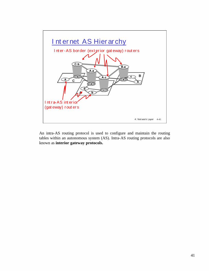
An intra-AS routing protocol is used to configure and maintain the routing tables within an autonomous system (AS). Intra-AS routing protocols are also known as interior gateway protocols.

42
4: Network Layer 4-42
Intra-AS and inter-AS RoutingIntra-AS routing:r Also known as Interior Gateway Protocols (IGP)r Most common IGPs:
m RIP: Routing Information Protocolm OSPF: Open Shortest Path Firstm EIGRP: Extended Interior Gateway Routing Protocol
(Cisco propr.)Inter-AS routing:r Also known as Exterior Gateway Protocols (EGP)r BGP (Border Gateway Protocol): the de facto standardWhy are there Different Inter-AS and Intra-AS Routing
Protocols?r Policyr Scaler Performance
Historically, three routing protocols have been used extensively for routing within an autonomous system in the Internet: RIP (the Routing Information Protocol), OSPF (Open Shortest Path First), and EIGRP (Cisco's propriety Enhanced Interior Gateway Routing Protocol).
The Border Gateway Protocol version 4, specified in RFC 1771 (see also RFC 1772; RFC 1773), is the de facto standard interdomain routing protocol in today's Internet. It is commonly referred to as BGP4 or simply as BGP. As an inter-autonomous system routing protocol, it provides for routing between autonomous systems (that is, administrative domains).
There are several resons for having different Inter-AS and Intra-AS routing protocols:
•Policy. Among ASs, policy issues dominate. It may well be important that traffic originating in a given AS specifically not be able to pass through another specific AS. Similarly, a given AS may well want to control what transit traffic it carries between other ASs. • Scale. The ability of a routing algorithm and its data structures to scale to handle routing to/among large numbers of networks is a critical issue in inter-AS routing. Within an AS, scalability is less of a concern.
•Performance. Because inter-AS routing is so policy-oriented, the quality (for example, performance) of the routes used is often of secondary concern.Indeed, among ASs, there is not even the notion of preference or costs associated with routes.

43
If your ever read commercial literature, you have to be aware of the difference between architecture names and implementation names. The word router (like most words) is unfortunately used in both contexts.
- from an architecture view point, a router is any system which forwards packets based on layer 3 information. Router in that context is a function.
- The router function can be implemented by a piece of software on Unix or Windows NT, or by a complex dedicated machine (a Cisco, IBM, Bay Networks or Flextel box for example).
Most boxes called “routers” perform a set of additional functions that have nothing to do with packet forwarding using layer 3 addresses. For example, they can be used as bridges or application level relay.
4: Network Layer 4-43
Router Definitionsr Definition: IP router
m a system that forwards packets based on IP addressesm performs packet forwarding + routing + control method
• routing, configuration management. DHCP relay, IPv6 router advertisements…
r Implementation: m any UNIX, NT machine can be configured as IP routerm normally, dedicated packet forwarder called router
r Multiprotocol routerm a system that forwards packets based on layer 3 addresses
for various protocol architectures (ex: IP, Appletalk)m CISCO, IBM, etc…m most multiprotocol routers works at both layer 2 and 3
• architecture: forward at layer 2 + forward at layer 3• implementation: one CISCO
m IP router boxes also perform other functions: port filtering, DHCP relay, …

44
4: Network Layer 4-44
Router Architecture Overview
Two key router functions:r run routing algorithms/protocol (RIP, OSPF, BGP)r switching datagrams from incoming to outgoing link
The routing algorithms control the routes taken by packets through the network In the network layer, the real work is the forwarding of datagrams, at first, between an incoming link and an outgoing link. The switching functionof a router is the transfer of datagrams from a router's incoming links to the appropriate outgoing links. The input port performs, among other functions,the physical layer functionality of terminating an incoming phys ical link to a router; and the data- link layer functionality needed to interoperate with the data link layer functionality on the other side of the incoming link. Theswitching fabric connects the router's input ports to its output ports. This switching fabric is completely contained within the router. The output portstores the packets that have been forwarded to it through the switching fabric, and then transmits the packets on the outgoing link. The output port thus performs the reverse data link and physical layer functionality as the input port. The routing processor executes the routing protocols, maintains the routing tables, and performs network management functions, within the router.

45
B (an old macintosh file server) runs only Appletalk. Only applications using the Appletalkprotocols can be used (MacOS file sharing, printing). TCP/IP applications such as the web cannot be used on B.
C (a modern PC) runs only TCP/IP. All TCP/IP applications can be used, but not MacOS file sharing.
A (a windows NT server) runs both in parallel. It can talk to both C and B.
A bridge can be used to interconnect A, B and C; there is nothing special to do. If a router is used instead, it must run in parallel Appletalk and IP.
The protocol stacks shown are all implemented in software. They use the standard Ethernet adapters.
4: Network Layer 4-45
Protocols Other than TCP/IPrSome other protocol families (ex: Appletalk,
IPX) are not compatible with TCP/IPr routers must be multiprotocolrMAC interface (layer 2) is standard
LLC
PHY
MAC
Appletalk
LLC
PHY
MAC
Appletalk
IP
TCP
PHY
MAC
IP
TCP
Bridgelayer 2
A B
C
multiprotocol

46
NetBIOS is an interface for distributed applications which is commonly used with IBM and Microsoft systems. Originally, NetBIOS used the LLC-2 protocol, a link layer protocol which does packet retransmissions, much as TCP does. Only MAC addresses are used. In addition,NetBIOS offers a naming service. This version of NetBIOS works only in a bridged environment.
4: Network Layer 4-46
NetBIOSr NetBIOS was originally developed to work only at
layer 2m uses broadcast that is blocked by routers: LLC-2 similar to
TCP but located in layer 2 (also called NETBEUI) m in that form, it is not “routable”: can only go at layer 2
r NetBIOS today is offered as a TCP/IP applicationm uses the NBT reserved portm Windows machines at EPFL use TCP/IP only
LLC2
PHY
MAC
NetBIOS
LLC2
PHY
MAC
NetBIOS
Layer 2
R1MACMAC
PHY R2
Bridge
App App

47
IPv6 is primarily IP with a larger address space. However, a number of details are different, in particular the IPv6 header is easier to process (but is also longer). An excellent online source of information about IPv6 is The IP Next Generation Homepage [Hinden 1999].
Many features which were originally designed for IPv6 are now part of IPv4 (security and mobility).
The most important changes introduced in IPv6 are evident in the packet format:
•Expanded addressing capabilities. IPv6 increases the size of the IP address from 32 to 128 bits. This ensures that the world won't run out of IP addresses. In addition to unicast and multicast addresses, a new type of address, called an anycast address, has also been introduced, which allows a packet addressed to an anycast address to be delivered to any one of a group of hosts.
•A streamlined 40-byte header. A number of IPv4 fields have been dropped or made optional. The resulting 40-byte fixed- length header allows for faster processing of the IP datagram. A new encoding of options allows for more flexible options processing.
•Flow labeling and priority. IPv6 has an elusive definition of a "flow. " RFC 1752 and RFC 2460 state that this allows "labeling of packets belonging to particular flows for which the sender requests special handling, such as a non-default quality of service or real-time service.
IPv6 is incompatible with IPv4; this is to avoid the IBM’s SNA syndrom (a monster of complexity,, because the last version is compatible with all details of all previous versions).Interworking between the two will use the dual stack approach, as shown for interworkingbetween Appletalk and IP.
4: Network Layer 4-47
IPv6r The current IP is IPv4r IPv4 address space is too small (32 bits)
m will be exhausted some dayr IPv6 is the new version of IP
m addresses are 128 bit longsm RFC 2460
r IPv6 is incompatible with IPv4
45b
prefix by prov.010 subnet interface Id
3b 64b16b
allocated by customerallocated by org / provider

48
4: Network Layer 4-48
Transition From IPv4 To IPv6r Not all routers can be upgraded simultaneous: no “flag days”
m How will the network operate with mixed IPv4 and IPv6 routers? r Two proposed approaches:
r Dual Stack: routers with both v6, v4 “translate” between formats
IPv6/IPv4 IPv4/IPv6

49
4: Network Layer 4-49
Transition From IPv4 To IPv6rTwo proposed approaches:
r Tunneling: v6 carried as payload in v4 datagram among v4 routers

50
4: Network Layer 4-50
Plug and Play and DHCPr IPv6 address is allocated automatically by
negotiation with routersm “stateless allocation”
r alternatively, Dynamic Host Configuration Protocol (DHCP) can be used
r DHCP can be used with IPv4 alsom DHCP server on LAN has a list of IP addresses that can
be allocated dynamicallym MAC address used to identify a host to DHCP serverm renumbering is possiblem more complex to use than IPv6 stateless allocation
With IPv6 an host can negotiate and get its IP address directly from the router which is attached to. As alternative the Dynamic Host Configuration Protocol (DHCP) [RFC 2131], also available for IPv4, and used for MobileIP, can be used
DHCP is sometimes referred to as Plug and Play. With DHCP, a DHCP server in a network (for example, in a LAN) receives DHCP requests from a client and, in the case of dynamic address allocation, allocates an IP address back to the requesting client. DHCP is used extensively in LANs and in residential Internet access.

51
A number of emerging network applications require the delivery of packets from one or more senders to a group of receivers. For each of these applications, an extremely useful abstraction is the notion of a multicast: the sending of a packet from one sender to multiple receivers with a single send operation.Clearly, this second approach toward multicast makes more efficient use of network bandwidth in that only a single copy of a datagram will ever traverse a link. On the other hand, considerable network layer support is needed to implement a multicast-aware network layer. Internet multicast is not a connectionless service--state information for a multicast connection must be established and maintained in routers that handle multicast packets sent among hosts in a so-called multicast group. This, in turn, will require a combination of signaling and routing protocols in order to set up, maintain, and tear down connection state in the routers. in the Internet architecture (and the ATM architecture as well), a multicast datagram is addressed using address indirection. That is, a single identifier is used for the group of receivers, and a copy of the datagram that is addressed to the group using this single identifier is delivered to all of the multicast receivers associated with that group. In the Internet, the single identifier that represents a group of receivers is a Class D multicast address. The group of receivers associated with a class D address is referred to as a multicast group. Multicast addresses are not allocated on a geographical basis. A global allocation scheme is under discussion at the IETF. Today, global scope addresses are allocated using the sd tool on Unix. Note that the unique IP unicast address of an host is completely independent of the address of the multicast group in which it is participating.
4: Network Layer 4-51
Broadcasting, Multicastingr Broadcast = send to all:
m sent to all hosts on one net/subnet ; usedby NetBIOSfor discovery
r Anycast = send to one in a groupm used in IPv6
r Multicast = send to a group m IP multicast address = class D = 224.0.0.0 to 239.255.255.255
224.0.0.1 = all multicast capable systems on subnet224.0.0.2 = all multicast capable routers on subnet
m used for: conferencing, radio distribution, …r IP uses open group paradigm
m multicast IP addresses are logical (= non topological)m for receiving data sent to multicast address m, a host
must subscribe to mm for sending to multicast address m, a host simply writes
m in the dest addr fieldr IP multicast is not a connectionless service

52
1 S sends data to multicast address m; there is no member, the data is simply lost at the router
2 A joins the multicast address m
3 R1 informs the rest of the network that m has a member at R1; the multicast routing protocol builds a tree. Data sent by S now reach A
4 B joins the multicast address m
5 R4 informs the rest of the network that m has a member at R4; the multicast routing protocol adds branches to the tree. Data sent by S now reach both A and B
4: Network Layer 4-52
IP Multicast Principles
R5R1
R2
R4
R3
A
B
S
r hosts subscribe via IGMP join messages sent to routerr routers build distribution tree via multicast routingr sources do not know who destinations arer packet duplication is done by routers
IGMP: join m
2
4
Multicast Routing
P
PP
P to m
1P33
R1R3
R2
5
5
R4
to m
1P

53
The mapping IP to MAC for multicast addresses is not unique. Ethernet hosts must filter up to 32 IP addresses for one MAC multicast address
4: Network Layer 4-53
IP Multicast Forwarding Algorithm
r Systems have to know which group they belong tom Hosts: application processes register to IP m Routers: learn if members present with IGMP
r Direct send to link layer: m algorithmic mapping of 23 last bits : ex : 224.2.166.207 ->
01-00-5E-02-A6-CF
Read address MA = destination IP@
/* assume it is multicast */for every physical interface PI
if MA is enabled on PI then send directly to PI
Read address MA = destination IP@
/* assume it is multicast */for every physical interface PI
if MA is enabled on PI then send directly to PI
send directly(MA, MAC@):map last 23 bits of MA to last 23 bits of MAC address
send MAC frame with DA = 01-00-5E-xx-xx-xx, SA = own i/f address
send directly(MA, MAC@):map last 23 bits of MA to last 23 bits of MAC address
send MAC frame with DA = 01-00-5E-xx-xx-xx, SA = own i/f address
Packet Forwarding (host, router)
Send directly (Ethernet, FDDI)
IP subnetMask
128.178.156.24224.2.166.207224.2.127.255
255.255.255.0
At lrcsuns: Physical Interface Tables

54
4: Network Layer 4-54
Purpose: manage group membership inside one subnetr routers: know if group is present on an interface
m know whether to forward locally or notr hosts: know if a multicast address is already in use
locally
IGMP: Internet Group Management Protocol
lrcsuns lrcpc1 lrcpc2 MCrouter
128.178.156.0
128.178.156.24 128.178.156.31 128.178.156.1
lrcpc2 is configured not to use multicast
lrcpc2 is configured not to use multicast
3
3: IGMP report, TTL =1, IGMP group @ = 224.2.127.255dest IP@ = 224.2.127.255; source IP@ = 128.178.156.24
1
1: IGMP query, TTL =1, IGMP group @ = 0dest IP@ = 224.0.0.1; source IP@ = 128.178.156.1
2
2: IGMP report, TTL =1, IGMP group @ = 224.2.166.207dest IP@ = 224.2.166.207; source IP@ = 128.178.156.24
The Internet Group Management Protocol, IGMP version 2 [RFC 2236], operates between a host and its directly attached router (e.g. S with R1, A with R5, etc..). It provides the means for a host to inform its attached router that an application running on the host wants to join a specific multicast group. TTL isin order to avoid broadcast propagation

55
(1): a first response is sent spontaneously, a short timer (10s) set, then another response sent afterexpiration (because of possible loss)
(2): a random timer is chosen
4: Network Layer 4-55
IGMP Host ImplementationHost Implementationr goal: avoid avalanche effects: one router
originated query might cause a burst of reportsr solution = the synchronization avoidance protocol
m 1. hosts delay responses randomlym 2. hosts listen to responses, only first one answers
MulticastAddressnot used
TimerActive Member
join group: (1)send response
leave group:
leave group:
response read:
timer expires:send responsequery read: (2)
event:action
Host IGMP Finite State Machine

56
4: Network Layer 4-56
MBone (1)r Global Multicast not available
m no stable routing protocol implemented in all routers of the Internetr Mbone = a network of “routers” supporting multicastTunneling used to build virtual linksr protocol = 4 in IP headerr example of use of a network layer as a layer 2 by another
networkm other examples: IPv6 over IPv4, IP over Frame Relay, over ATM,
AppleTalk over IP, etc.r MBone “hacks”
m limitation of multicast enforced by Mbone routers on TTL fieldm multicast routing with Distance Vector Multicast Routing Protocol
(DVMRP) • each router computes SPT from each source using distance vector
algorithm• reverse path forwarding (RPF)
Mbone (1)
The Multicast Backbone (MBONE) is a virtual network. It is layered on top of portions of the physical Internet to support routing of IP multicast packets since that function has not yet been integrated into many production routers. The network is composed of islands that can directly support IP multicast, such as multicast LANs like Ethernet, linked by virtual point-to-point links called "tunnels". The tunnel endpoints are typically workstation-class machines having operating system support for IP multicast and running the "mrouted" multicast routing daemon. IP multicast packets are encapsulated for transmission through tunnels, so that they look like normal unicast datagrams to intervening routers and subnets. A multicast router that wants to send a multicast packet across a tunnel will prepend another IP header, set the destination address in the new header to be the unicast address of the multicast router at the other end of the tunnel, and set the IP protocol field in the new header to be 4 (which means the next protocol is IP). The multicast router at the other end of the tunnel receives the packet, strips off the encapsulating IP header, and forwards the packet as appropriate. Each tunnel has an associated threshold against which the packet's IP time-to-live (TTL) value is compared. Currently, all MBONE applications use UDP.
Distance Vector Multicast Routing Protocol (DVMRP) allows each router to compute the outgoing link (next hop) that is on its shortest path back to each possible source. With the reverse path forwarding (RPF) algorithm, when a router receives a multicast packet with a given source address, it transmits the packet on all of its outgoing links (except the one on which it was received) only if the packet arrived on the link that is on its own shortest path back to the sender. Otherwise, the router simply discards the incoming packet without forwarding it on any of its outgoing links.

57
4: Network Layer 4-57
Mbone (2)
dest IP addr srce IP addr prot IP packet data part1 224.2.165.231 128.178.156.24 UDP bla bla2a 129.132.2.89 128.178.100.67 IP 224.2.165.231 128.178.156.24 UDP bla bla3a 129.132.2.89 128.178.100.67 IP 224.2.165.231 128.178.156.24 UDP bla bla4a 224.2.165.231 128.178.156.24 UDP
MBone routers
Internet
1 4a
4b128.178.156.24
9.141.49.67
129.132.99.67
9.141.1.3
128.178.100.67 129.132.2.89
B
AS
2a
2b
3a
3b
Suppose the host 128.178.156.24 wants to communicate with the Mbonemulticast group. It sends (with multicast routing) the packet inside its local area (EPFL). When the multicast packet (UDP) reaches the Mbone-connected router (128.178.100.67) it is encapsuleted within an IP packet and sent it within the Internet to the other IP multicast routers connected with tunnels to this MBone.multicast group. For example, it reaches the router 129.132.2.89,which has a participant to the MBone.multicast group (129.132.99.67).
At EPFL, IP multicast is supported as follows:(1) inside EPFL, CISCO routers support Multicast IP; (2) scoping is by use of TTL:
TTL < 8: inside LRC
TTL < 16: inside DI
TTL < 32 inside Ecublens
TTL < 64: inside EPFL
TTL = 127: world wide
The routing inside EPFL is done with PIM, outside via Mbone
-to know more about multicast ingeneral: http://www. ipmulticast.com
-at EPFL http://stiwww.epfl.ch/mbone/mbone.html

58
4: Network Layer 4-58
MulticastSocket
r DatagramSocket with joining group capabilities
r Two public constructorsr Socket out of the group can
send to the group
java.lang.Object
|
+--java.net.DatagramSocket
|+--java.net.MulticastSocket
public class Socket
extends DatagramSocket
The multicast datagram socket class is useful for sending and receiving IP multicast packets. A MulticastSocket is a (UDP) DatagramSocket, with additional capabilities for joining "groups" of other multicast hosts on the internet.
One would join a multicast group by first creating a MulticastSocket with the desired port, 224.0.0.1 to 239.255.255.255, inclusive, then invoking the joinGroup(InetAddress groupAddr) method:
When one sends a message to a multicast group, all subscribing recipients to that host and port receive the message (within the time-to- live range of the packet). The socket need not be a member of the multicast group to send messages to it.
When a socket subscribes to a multicast group/port, it receives datagrams sent by other hosts to the group/port, as do all other members of the group and port. A socket relinquishes membership in a group by the leaveGroup(InetAddress addr) method. Multiple MulticastSocket's may subscribe to a multicast group and port concurrently, and they will all receive group datagrams.

59
4: Network Layer 4-59
Constructors and main methodsr public MulticastSocket() throws IOExceptionr public MulticastSocket(int port) throws
IOExceptionr public void joinGroup(InetAddress mcastaddr) throws
IOException
r public void leaveGroup(InetAddress mcastaddr) throws IOException
r public void send(DatagramPacket p, byte ttl) throws IOException
r public void setTimeToLive(int ttl) throws IOException
CONSTRUCTORS
MulticastSocket() throws IOException
Create a multicast socket.
MulticastSocket(int port) throws IOException
Create a multicast socket and bind it to a specific port.
MAIN METHODS
public void joinGroup(InetAddress mcastaddr) throws IOException
Joins a multicast group.Its behavior may be affected by setInterface. If there is a security manager, this method first calls its checkMulticast method with themcastaddr argument as its argument.
public void leaveGroup(InetAddress mcastaddr) throws IOException
Leave a multicast group. Its behavior may be affected by setInterface. If there is a security manager, this method first calls its checkMulticast method with the mcastaddr argument as its argument.
public void send(DatagramPacket p, byte ttl) throws IOException
Sends a datagram packet to the destination, with a TTL (time- to- live) other than the default for the socket. This method need only be used in instances where a particular TTL is desired; otherwise it is preferable to set a TTL once on the socket, and use that default TTL for all packets.
public void setTimeToLive(int ttl) throws IOException
Set the default time-to- live for multicast packets sent out on this socket. The TTL sets the IP time-to- live for DatagramPackets sent to a MulticastGroup, which specifies how many "hops" that the packet will be forwarded on the

60
4: Network Layer 4-60
Example…..byte[] msg = {'H', 'e', 'l', 'l', 'o'};InetAddress group = InetAddress.getByName("228.5.6.7");MulticastSocket s = new MulticastSocket(6789);s.joinGroup(group);DatagramPacket hi = new DatagramPacket(msg, msg.length, group,
6789);s.send(hi);// get their responses!byte[] buf = new byte[1000];DatagramPacket recv = new DatagramPacket(buf, buf.length);s.receive(recv);// OK, I'm done talking - leave the group...s.leaveGroup(group);
…..
In the example we see how to join a Multicast group and send the group salutations.The MulticastSocket s, that is a DatagramSocket, uses the DatagramPacket for building the datagram, which is then sent with the send() method.

61
4: Network Layer 4-61
Summaryr The network layer transports packets from a sending host to
the receiver host.r Main components:
m addressingm routing m routers (and how a router works)
r advanced topics: IPv6, multicastr the Internet network layer
m Connectionlessm Best-effort