chapter 4 network layer - uic computer sciencejbell/coursenotes/networking/slides/... · computer...
TRANSCRIPT

Chapter 4 Network Layer
Computer Networking: A Top Down Approach 6th edition Jim Kurose, Keith Ross Addison-Wesley March 2012
A note on the use of these ppt slides: We’re making these slides freely available to all (faculty, students, readers).
They’re in PowerPoint form so you see the animations; and can add, modify,
and delete slides (including this one) and slide content to suit your needs.
They obviously represent a lot of work on our part. In return for use, we only
ask the following: If you use these slides (e.g., in a class) that you mention their source
(after all, we’d like people to use our book!)
If you post any slides on a www site, that you note that they are adapted
from (or perhaps identical to) our slides, and note our copyright of this
material.
Thanks and enjoy! JFK/KWR All material copyright 1996-2012 J.F Kurose and K.W. Ross, All Rights Reserved
Network Layer 4-1
Network Layer 4-2
Chapter 4: network layer
chapter goals: understand principles behind network layer
services: network layer service models
forwarding versus routing
how a router works
routing (path selection)
broadcast, multicast
instantiation, implementation in the Internet

Network Layer 4-3
4.1 introduction
4.2 virtual circuit and datagram networks
4.3 what’s inside a router
4.4 IP: Internet Protocol datagram format
IPv4 addressing
ICMP
IPv6
4.5 routing algorithms link state
distance vector
hierarchical routing
4.6 routing in the Internet RIP
OSPF
BGP
4.7 broadcast and multicast routing
Chapter 4: outline

Network Layer 4-4
Network layer
transport segment from sending to receiving host
on sending side encapsulates segments into datagrams
on receiving side, delivers segments to transport layer
network layer protocols in every host, router
router examines header fields in all IP datagrams passing through it
application
transport
network
data link
physical
application
transport
network
data link
physical
network
data link
physical
network
data link
physical
network
data link
physical
network
data link
physical
network
data link
physical
network
data link
physical
network
data link
physical
network
data link
physical
network
data link
physical
network
data link
physical
network
data link
physical
Network Layer 4-5
Two key network-layer functions
forwarding: move packets from router’s input to appropriate router output
routing: determine route taken by packets from source to dest.
routing algorithms
analogy:
routing: process of planning trip from source to dest
forwarding: process of getting through single interchange
Network Layer 4-6
1
2 3
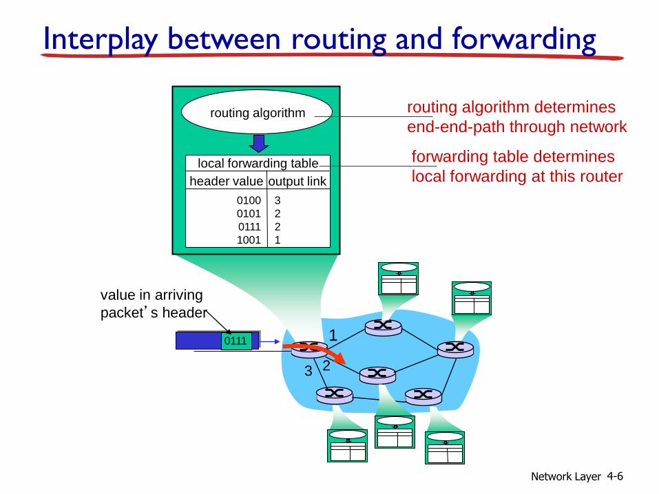
0111
value in arriving
packet’s header
routing algorithm
local forwarding table
header value output link
0100
0101
0111
1001
3
2
2
1
Interplay between routing and forwarding
routing algorithm determines
end-end-path through network
forwarding table determines
local forwarding at this router
Network Layer 4-7
Connection setup
3rd important function in some network architectures: ATM, frame relay, X.25
before datagrams flow, two end hosts and intervening routers establish virtual connection routers get involved
network vs transport layer connection service: network: between two hosts (may also involve intervening
routers in case of VCs)
transport: between two processes

Network Layer 4-8
Network service model
Q: What service model for “channel” transporting
datagrams from sender to receiver?
example services for individual datagrams:
guaranteed delivery
guaranteed delivery with less than 40 msec delay
example services for a flow of datagrams:
in-order datagram delivery
guaranteed minimum bandwidth to flow
restrictions on changes in inter-packet spacing
Network Layer 4-9
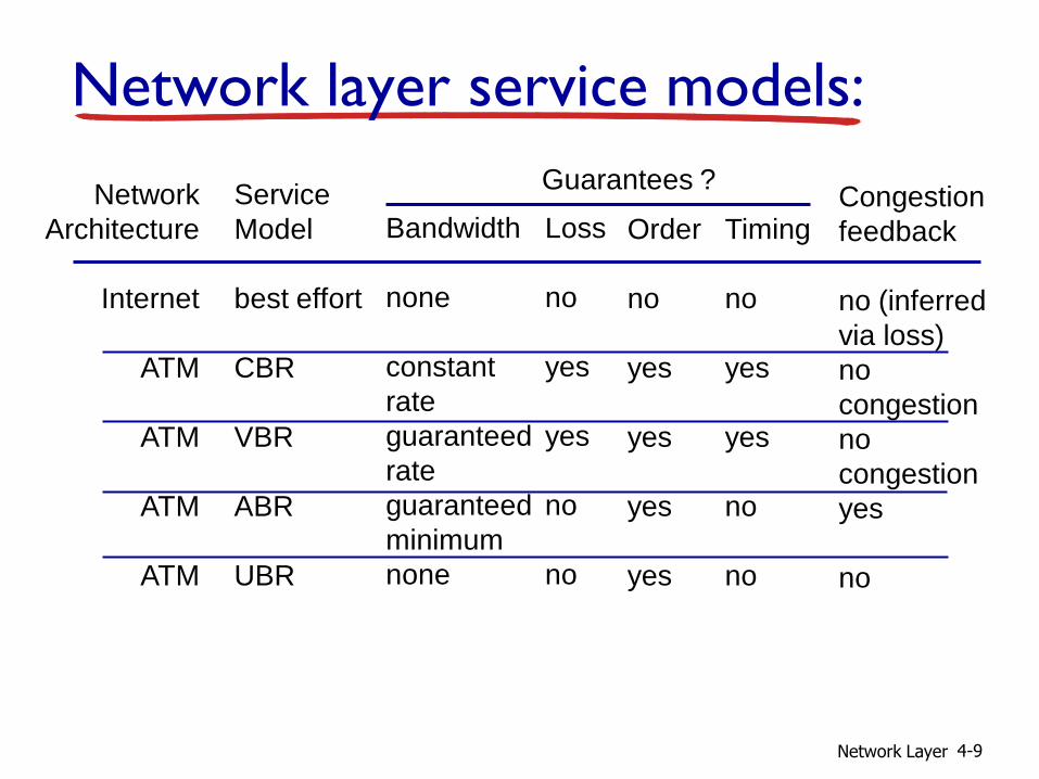
Network layer service models:
Network
Architecture
Internet
ATM
ATM
ATM
ATM
Service
Model
best effort
CBR
VBR
ABR
UBR
Bandwidth
none
constant
rate
guaranteed
rate
guaranteed
minimum
none
Loss
no
yes
yes
no
no
Order
no
yes
yes
yes
yes
Timing
no
yes
yes
no
no
Congestion
feedback
no (inferred
via loss)
no
congestion
no
congestion
yes
no
Guarantees ?
Network Layer 4-10
4.1 introduction
4.2 virtual circuit and datagram networks
4.3 what’s inside a router
4.4 IP: Internet Protocol datagram format
IPv4 addressing
ICMP
IPv6
4.5 routing algorithms link state
distance vector
hierarchical routing
4.6 routing in the Internet RIP
OSPF
BGP
4.7 broadcast and multicast routing
Chapter 4: outline

Network Layer 4-11
Connection, connection-less service
datagram network provides network-layer connectionless service
virtual-circuit network provides network-layer connection service
analogous to TCP/UDP connecton-oriented / connectionless transport-layer services, but:
service: host-to-host
no choice: network provides one or the other
implementation: in network core

Network Layer 4-12
Virtual circuits
call setup, teardown for each call before data can flow
each packet carries VC identifier (not destination host address)
every router on source-dest path maintains “state” for each passing connection
link, router resources (bandwidth, buffers) may be allocated to VC (dedicated resources = predictable service)
“source-to-dest path behaves much like telephone circuit” performance-wise
network actions along source-to-dest path
Network Layer 4-13
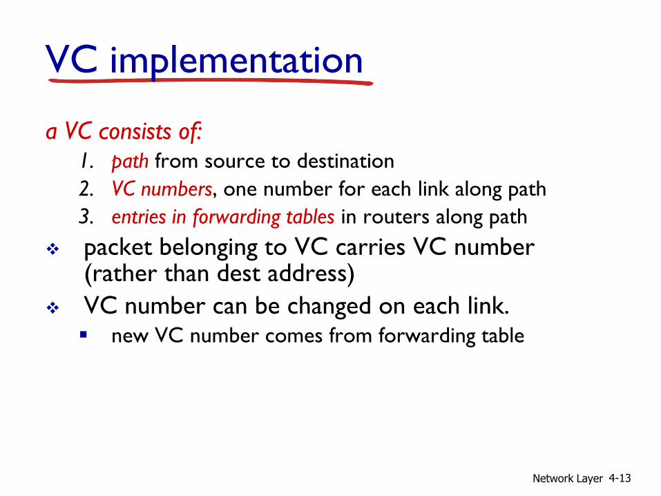
VC implementation
a VC consists of: 1. path from source to destination
2. VC numbers, one number for each link along path
3. entries in forwarding tables in routers along path
packet belonging to VC carries VC number (rather than dest address)
VC number can be changed on each link. new VC number comes from forwarding table

Network Layer 4-14
VC forwarding table
12 22 32
1 2
3
VC number
interface number
Incoming interface Incoming VC # Outgoing interface Outgoing VC #
1 12 3 22
2 63 1 18
3 7 2 17
1 97 3 87
… … … …
forwarding table in northwest router:
VC routers maintain connection state information!
Network Layer 4-15
application
transport
network
data link
physical
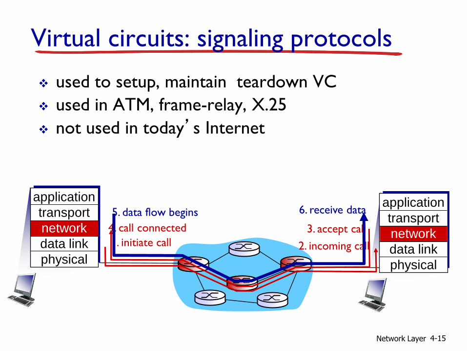
Virtual circuits: signaling protocols
used to setup, maintain teardown VC
used in ATM, frame-relay, X.25
not used in today’s Internet
1. initiate call 2. incoming call 3. accept call 4. call connected
5. data flow begins 6. receive data application
transport
network
data link
physical
Network Layer 4-16
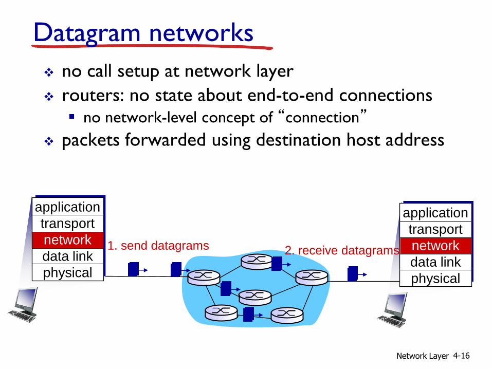
Datagram networks
no call setup at network layer
routers: no state about end-to-end connections no network-level concept of “connection”
packets forwarded using destination host address
1. send datagrams
application
transport
network
data link
physical
application
transport
network
data link
physical
2. receive datagrams

Network Layer 4-17
1
2 3
Datagram forwarding table
IP destination address in
arriving packet’s header
routing algorithm
local forwarding table
dest address output link
address-range 1
address-range 2
address-range 3
address-range 4
3
2
2
1
4 billion IP addresses, so rather than list individual destination address list range of addresses (aggregate table entries)

Network Layer 4-18
Destination Address Range
11001000 00010111 00010000 00000000
through 11001000 00010111 00010111 11111111
11001000 00010111 00011000 00000000
through 11001000 00010111 00011000 11111111
11001000 00010111 00011001 00000000
through 11001000 00010111 00011111 11111111
otherwise
Link Interface
0
1
2
3
Q: but what happens if ranges don’t divide up so nicely?
Datagram forwarding table

Network Layer 4-19
Longest prefix matching
Destination Address Range
11001000 00010111 00010*** *********
11001000 00010111 00011000 *********
11001000 00010111 00011*** *********
otherwise
DA: 11001000 00010111 00011000 10101010
examples:
DA: 11001000 00010111 00010110 10100001 which interface?
which interface?
when looking for forwarding table entry for given destination address, use longest address prefix that matches destination address.
longest prefix matching
Link interface
0
1
2
3

Network Layer 4-20
Datagram or VC network: why?
Internet (datagram) data exchange among
computers “elastic” service, no strict
timing req.
many link types different characteristics
uniform service difficult
“smart” end systems (computers) can adapt, perform control,
error recovery
simple inside network, complexity at “edge”
ATM (VC) evolved from telephony human conversation:
strict timing, reliability requirements
need for guaranteed service
“dumb” end systems telephones complexity inside
network

Network Layer 4-21
4.1 introduction
4.2 virtual circuit and datagram networks
4.3 what’s inside a router
4.4 IP: Internet Protocol datagram format
IPv4 addressing
ICMP
IPv6
4.5 routing algorithms link state
distance vector
hierarchical routing
4.6 routing in the Internet RIP
OSPF
BGP
4.7 broadcast and multicast routing
Chapter 4: outline

Network Layer 4-22
Router architecture overview two key router functions: run routing algorithms/protocol (RIP, OSPF, BGP)
forwarding datagrams from incoming to outgoing link
high-seed switching
fabric
routing processor
router input ports router output ports
forwarding data
plane (hardware)
routing, management
control plane (software)
forwarding tables computed,
pushed to input ports

Network Layer 4-23
line
termination
link layer
protocol (receive)
lookup,
forwarding
queueing
Input port functions
decentralized switching:
given datagram dest., lookup output port using forwarding table in input port memory (“match plus action”)
goal: complete input port processing at ‘line speed’
queuing: if datagrams arrive faster than forwarding rate into switch fabric
physical layer:
bit-level reception
data link layer:
e.g., Ethernet
see chapter 5
switch fabric
Network Layer 4-24
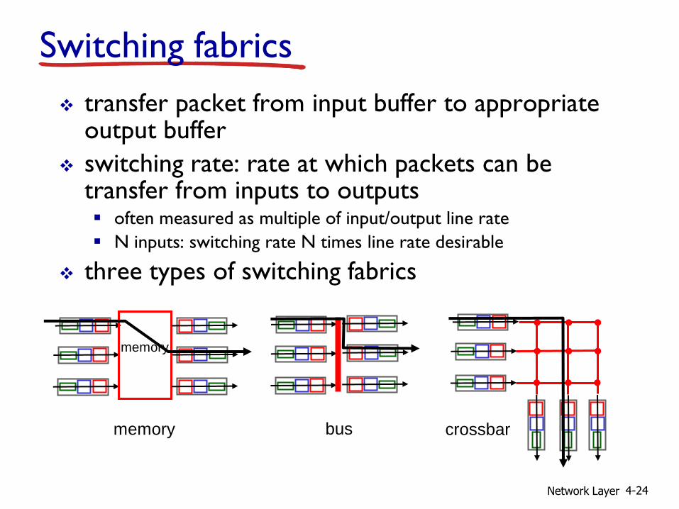
Switching fabrics
transfer packet from input buffer to appropriate output buffer
switching rate: rate at which packets can be transfer from inputs to outputs often measured as multiple of input/output line rate
N inputs: switching rate N times line rate desirable
three types of switching fabrics
memory
memory
bus crossbar
Network Layer 4-25
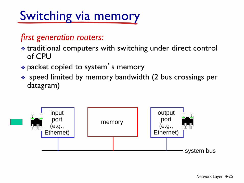
Switching via memory
first generation routers: traditional computers with switching under direct control
of CPU
packet copied to system’s memory
speed limited by memory bandwidth (2 bus crossings per datagram)
input port (e.g.,
Ethernet)
memory
output port (e.g.,
Ethernet)
system bus
Network Layer 4-26
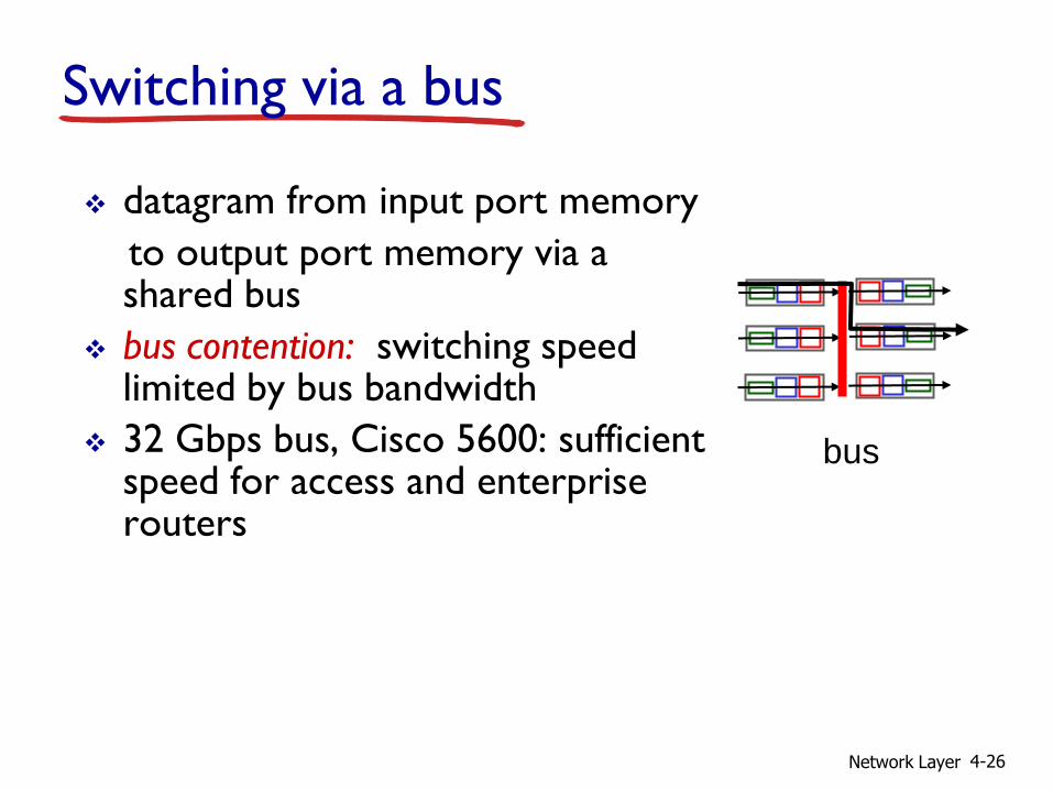
Switching via a bus
datagram from input port memory
to output port memory via a shared bus
bus contention: switching speed limited by bus bandwidth
32 Gbps bus, Cisco 5600: sufficient speed for access and enterprise routers
bus

Network Layer 4-27
Switching via interconnection network
overcome bus bandwidth limitations
banyan networks, crossbar, other interconnection nets initially developed to connect processors in multiprocessor
advanced design: fragmenting datagram into fixed length cells, switch cells through the fabric.
Cisco 12000: switches 60 Gbps through the interconnection network
crossbar

Network Layer 4-28
Output ports
buffering required when datagrams arrive from fabric faster than the transmission rate
scheduling discipline chooses among queued datagrams for transmission
line
termination
link layer
protocol (send)
switch fabric
datagram
buffer
queueing

Network Layer 4-29
Output port queueing
buffering when arrival rate via switch exceeds output line speed
queueing (delay) and loss due to output port buffer overflow!
at t, packets more
from input to output
one packet time later
switch
fabric
switch
fabric
Network Layer 4-30
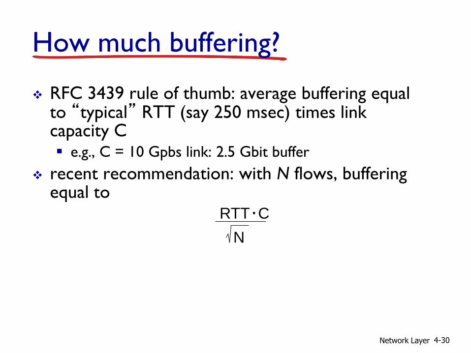
How much buffering?
RFC 3439 rule of thumb: average buffering equal to “typical” RTT (say 250 msec) times link capacity C e.g., C = 10 Gpbs link: 2.5 Gbit buffer
recent recommendation: with N flows, buffering equal to
RTT C .
N

Network Layer 4-31
Input port queuing
fabric slower than input ports combined -> queueing may occur at input queues
queueing delay and loss due to input buffer overflow!
Head-of-the-Line (HOL) blocking: queued datagram at front of queue prevents others in queue from moving forward
output port contention:
only one red datagram can be
transferred.
lower red packet is blocked
switch
fabric
one packet time later:
green packet
experiences HOL
blocking
switch
fabric

Network Layer 4-32
4.1 introduction
4.2 virtual circuit and datagram networks
4.3 what’s inside a router
4.4 IP: Internet Protocol datagram format
IPv4 addressing
ICMP
IPv6
4.5 routing algorithms link state
distance vector
hierarchical routing
4.6 routing in the Internet RIP
OSPF
BGP
4.7 broadcast and multicast routing
Chapter 4: outline
Network Layer 4-33
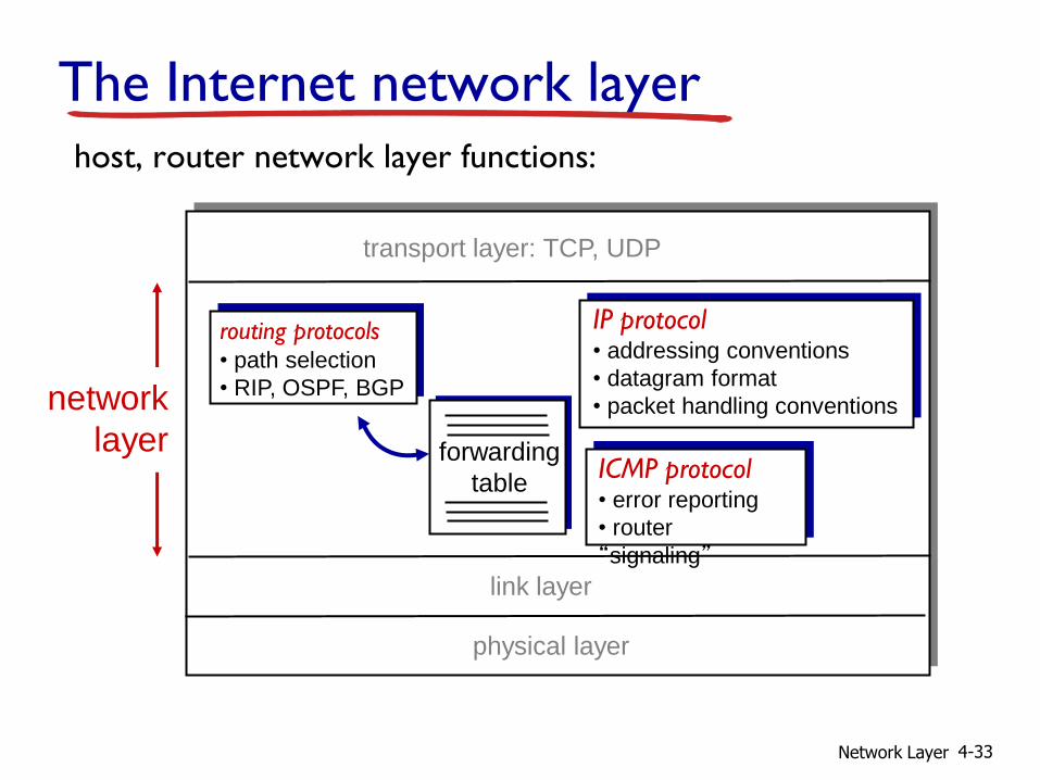
The Internet network layer
forwarding
table
host, router network layer functions:
routing protocols • path selection
• RIP, OSPF, BGP
IP protocol • addressing conventions
• datagram format
• packet handling conventions
ICMP protocol • error reporting
• router
“signaling”
transport layer: TCP, UDP
link layer
physical layer
network
layer

Network Layer 4-34
ver length
32 bits
data
(variable length,
typically a TCP
or UDP segment)
16-bit identifier
header
checksum
time to
live
32 bit source IP address
head.
len
type of
service flgs
fragment
offset upper
layer
32 bit destination IP address
options (if any)
IP datagram format IP protocol version
number
header length
(bytes)
upper layer protocol
to deliver payload to
total datagram
length (bytes)
“type” of data
for
fragmentation/
reassembly max number
remaining hops
(decremented at
each router)
e.g. timestamp,
record route
taken, specify
list of routers
to visit.
how much overhead?
20 bytes of TCP
20 bytes of IP
= 40 bytes + app layer overhead
Network Layer 4-35
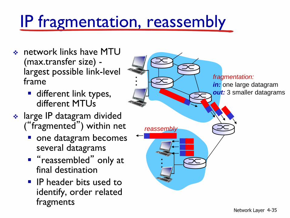
IP fragmentation, reassembly
network links have MTU (max.transfer size) - largest possible link-level frame
different link types, different MTUs
large IP datagram divided (“fragmented”) within net
one datagram becomes several datagrams
“reassembled” only at final destination
IP header bits used to identify, order related fragments
fragmentation:
in: one large datagram
out: 3 smaller datagrams
reassembly
…
…

Network Layer 4-36
ID
=x offset
=0
fragflag
=0
length
=4000
ID
=x offset
=0
fragflag
=1
length
=1500
ID
=x offset
=185
fragflag
=1
length
=1500
ID
=x offset
=370
fragflag
=0
length
=1040
one large datagram becomes
several smaller datagrams
example: 4000 byte datagram
MTU = 1500 bytes
1480 bytes in
data field
offset =
1480/8
IP fragmentation, reassembly

Network Layer 4-37
4.1 introduction
4.2 virtual circuit and datagram networks
4.3 what’s inside a router
4.4 IP: Internet Protocol datagram format
IPv4 addressing
ICMP
IPv6
4.5 routing algorithms link state
distance vector
hierarchical routing
4.6 routing in the Internet RIP
OSPF
BGP
4.7 broadcast and multicast routing
Chapter 4: outline

Network Layer 4-38
IP addressing: introduction
IP address: 32-bit identifier for host, router interface
interface: connection between host/router and physical link router’s typically have
multiple interfaces
host typically has one or two interfaces (e.g., wired Ethernet, wireless 802.11)
IP addresses associated with each interface
223.1.1.1
223.1.1.2
223.1.1.3
223.1.1.4 223.1.2.9
223.1.2.2
223.1.2.1
223.1.3.2 223.1.3.1
223.1.3.27
223.1.1.1 = 11011111 00000001 00000001 00000001
223 1 1 1
Network Layer 4-39
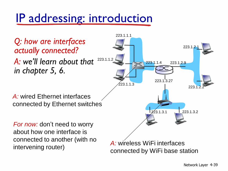
IP addressing: introduction
Q: how are interfaces actually connected?
A: we’ll learn about that in chapter 5, 6.
223.1.1.1
223.1.1.2
223.1.1.3
223.1.1.4 223.1.2.9
223.1.2.2
223.1.2.1
223.1.3.2 223.1.3.1
223.1.3.27
A: wired Ethernet interfaces
connected by Ethernet switches
A: wireless WiFi interfaces
connected by WiFi base station
For now: don’t need to worry
about how one interface is
connected to another (with no
intervening router)
Network Layer 4-40
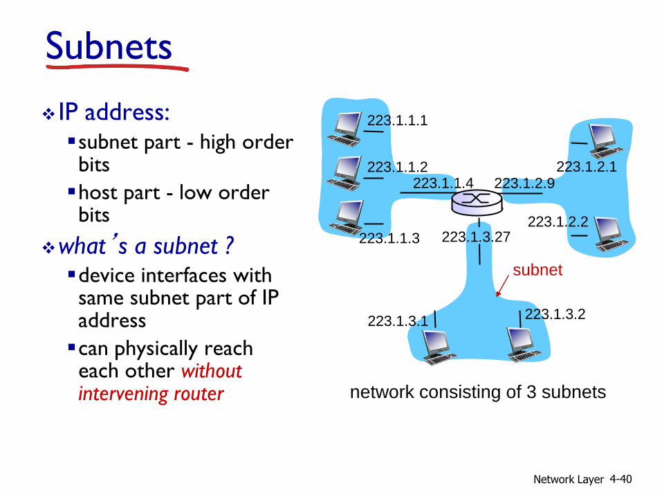
Subnets
IP address: subnet part - high order bits
host part - low order bits
what’s a subnet ? device interfaces with same subnet part of IP address
can physically reach each other without intervening router network consisting of 3 subnets
223.1.1.1
223.1.1.3
223.1.1.4 223.1.2.9
223.1.3.2 223.1.3.1
subnet
223.1.1.2
223.1.3.27 223.1.2.2
223.1.2.1
Network Layer 4-41
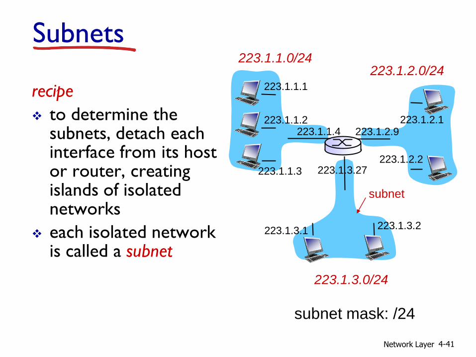
recipe
to determine the subnets, detach each interface from its host or router, creating islands of isolated networks
each isolated network is called a subnet
subnet mask: /24
Subnets 223.1.1.0/24
223.1.2.0/24
223.1.3.0/24
223.1.1.1
223.1.1.3
223.1.1.4 223.1.2.9
223.1.3.2 223.1.3.1
subnet
223.1.1.2
223.1.3.27 223.1.2.2
223.1.2.1

Network Layer 4-42
how many? 223.1.1.1
223.1.1.3
223.1.1.4
223.1.2.2 223.1.2.1
223.1.2.6
223.1.3.2 223.1.3.1
223.1.3.27
223.1.1.2
223.1.7.0
223.1.7.1 223.1.8.0 223.1.8.1
223.1.9.1
223.1.9.2
Subnets
Network Layer 4-43
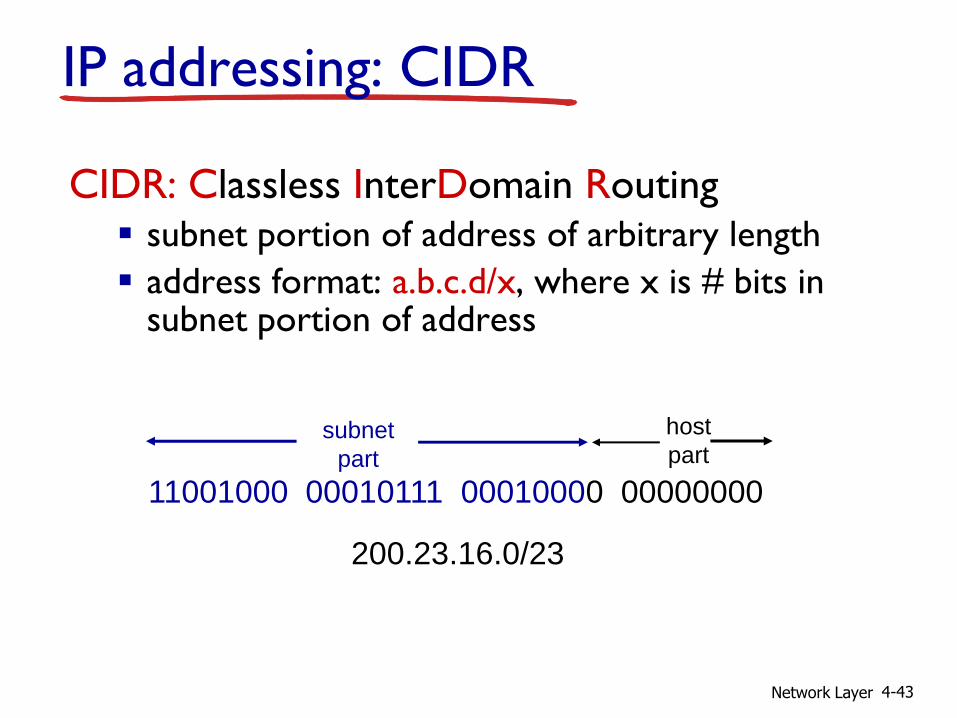
IP addressing: CIDR
CIDR: Classless InterDomain Routing subnet portion of address of arbitrary length
address format: a.b.c.d/x, where x is # bits in subnet portion of address
11001000 00010111 00010000 00000000
subnet
part
host
part
200.23.16.0/23

Network Layer 4-44
IP addresses: how to get one?
Q: How does a host get IP address?
hard-coded by system admin in a file Windows: control-panel->network->configuration-
>tcp/ip->properties
UNIX: /etc/rc.config
DHCP: Dynamic Host Configuration Protocol: dynamically get address from as server
“plug-and-play”
Network Layer 4-45
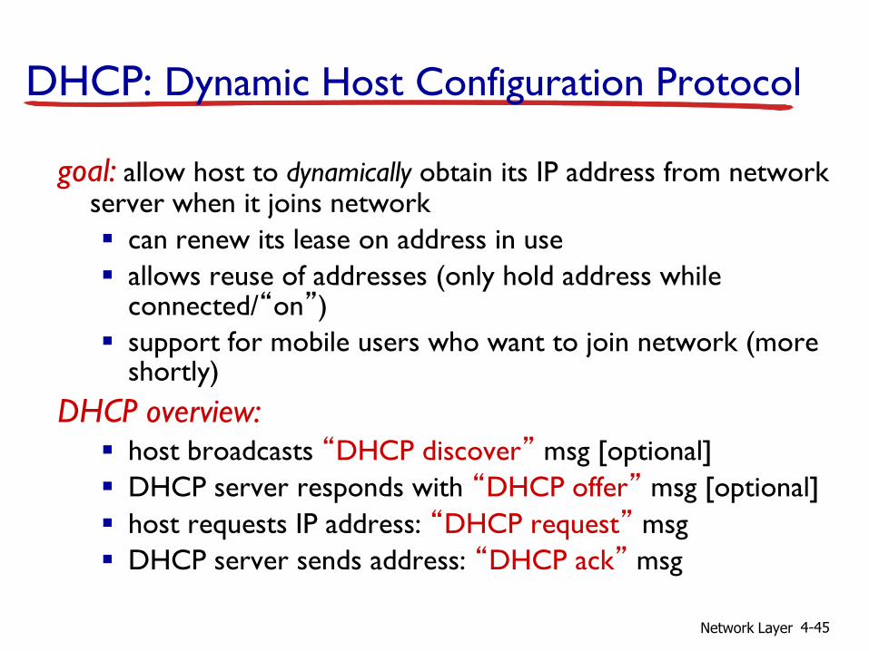
DHCP: Dynamic Host Configuration Protocol
goal: allow host to dynamically obtain its IP address from network server when it joins network
can renew its lease on address in use
allows reuse of addresses (only hold address while connected/“on”)
support for mobile users who want to join network (more shortly)
DHCP overview: host broadcasts “DHCP discover” msg [optional]
DHCP server responds with “DHCP offer” msg [optional]
host requests IP address: “DHCP request” msg
DHCP server sends address: “DHCP ack” msg

Network Layer 4-46
DHCP client-server scenario
223.1.1.0/24
223.1.2.0/24
223.1.3.0/24
223.1.1.1
223.1.1.3
223.1.1.4 223.1.2.9
223.1.3.2 223.1.3.1
223.1.1.2
223.1.3.27 223.1.2.2
223.1.2.1
DHCP server
arriving DHCP client needs address in this network

Network Layer 4-47
DHCP server: 223.1.2.5 arriving client
DHCP discover
src : 0.0.0.0, 68
dest.: 255.255.255.255,67
yiaddr: 0.0.0.0
transaction ID: 654
DHCP offer
src: 223.1.2.5, 67
dest: 255.255.255.255, 68
yiaddrr: 223.1.2.4
transaction ID: 654
lifetime: 3600 secs DHCP request
src: 0.0.0.0, 68
dest:: 255.255.255.255, 67
yiaddrr: 223.1.2.4
transaction ID: 655
lifetime: 3600 secs
DHCP ACK
src: 223.1.2.5, 67
dest: 255.255.255.255, 68
yiaddrr: 223.1.2.4
transaction ID: 655
lifetime: 3600 secs
DHCP client-server scenario

Network Layer 4-48
DHCP: more than IP addresses
DHCP can return more than just allocated IP address on subnet: address of first-hop router for client
name and IP address of DNS sever
network mask (indicating network versus host portion of address)
Network Layer 4-49
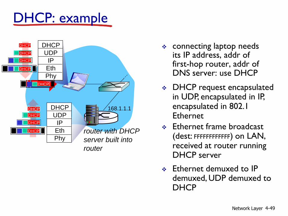
connecting laptop needs its IP address, addr of first-hop router, addr of DNS server: use DHCP
router with DHCP
server built into
router
DHCP request encapsulated in UDP, encapsulated in IP, encapsulated in 802.1 Ethernet
Ethernet frame broadcast (dest: FFFFFFFFFFFF) on LAN, received at router running DHCP server
Ethernet demuxed to IP demuxed, UDP demuxed to DHCP
168.1.1.1
DHCP
UDP
IP
Eth
Phy
DHCP
DHCP
DHCP
DHCP
DHCP
DHCP
UDP
IP
Eth
Phy
DHCP
DHCP
DHCP
DHCP DHCP
DHCP: example
Network Layer 4-50
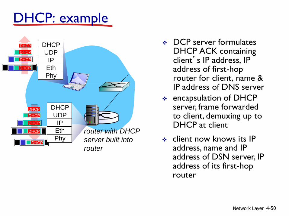
DCP server formulates DHCP ACK containing client’s IP address, IP address of first-hop router for client, name & IP address of DNS server encapsulation of DHCP server, frame forwarded to client, demuxing up to DHCP at client
DHCP: example
router with DHCP
server built into
router
DHCP
DHCP
DHCP
DHCP
DHCP
UDP
IP
Eth
Phy
DHCP
DHCP
UDP
IP
Eth
Phy
DHCP
DHCP
DHCP
DHCP
client now knows its IP address, name and IP address of DSN server, IP address of its first-hop router

Network Layer 4-51
DHCP: Wireshark output (home LAN)
Message type: Boot Reply (2) Hardware type: Ethernet Hardware address length: 6 Hops: 0 Transaction ID: 0x6b3a11b7 Seconds elapsed: 0 Bootp flags: 0x0000 (Unicast) Client IP address: 192.168.1.101 (192.168.1.101) Your (client) IP address: 0.0.0.0 (0.0.0.0) Next server IP address: 192.168.1.1 (192.168.1.1) Relay agent IP address: 0.0.0.0 (0.0.0.0) Client MAC address: Wistron_23:68:8a (00:16:d3:23:68:8a) Server host name not given Boot file name not given Magic cookie: (OK) Option: (t=53,l=1) DHCP Message Type = DHCP ACK Option: (t=54,l=4) Server Identifier = 192.168.1.1 Option: (t=1,l=4) Subnet Mask = 255.255.255.0 Option: (t=3,l=4) Router = 192.168.1.1 Option: (6) Domain Name Server Length: 12; Value: 445747E2445749F244574092; IP Address: 68.87.71.226; IP Address: 68.87.73.242; IP Address: 68.87.64.146 Option: (t=15,l=20) Domain Name = "hsd1.ma.comcast.net."
reply
Message type: Boot Request (1) Hardware type: Ethernet Hardware address length: 6 Hops: 0 Transaction ID: 0x6b3a11b7 Seconds elapsed: 0 Bootp flags: 0x0000 (Unicast) Client IP address: 0.0.0.0 (0.0.0.0) Your (client) IP address: 0.0.0.0 (0.0.0.0) Next server IP address: 0.0.0.0 (0.0.0.0) Relay agent IP address: 0.0.0.0 (0.0.0.0) Client MAC address: Wistron_23:68:8a (00:16:d3:23:68:8a) Server host name not given Boot file name not given Magic cookie: (OK) Option: (t=53,l=1) DHCP Message Type = DHCP Request Option: (61) Client identifier Length: 7; Value: 010016D323688A; Hardware type: Ethernet Client MAC address: Wistron_23:68:8a (00:16:d3:23:68:8a) Option: (t=50,l=4) Requested IP Address = 192.168.1.101 Option: (t=12,l=5) Host Name = "nomad" Option: (55) Parameter Request List Length: 11; Value: 010F03062C2E2F1F21F92B 1 = Subnet Mask; 15 = Domain Name 3 = Router; 6 = Domain Name Server 44 = NetBIOS over TCP/IP Name Server ……
request
Network Layer 4-52
IP addresses: how to get one?
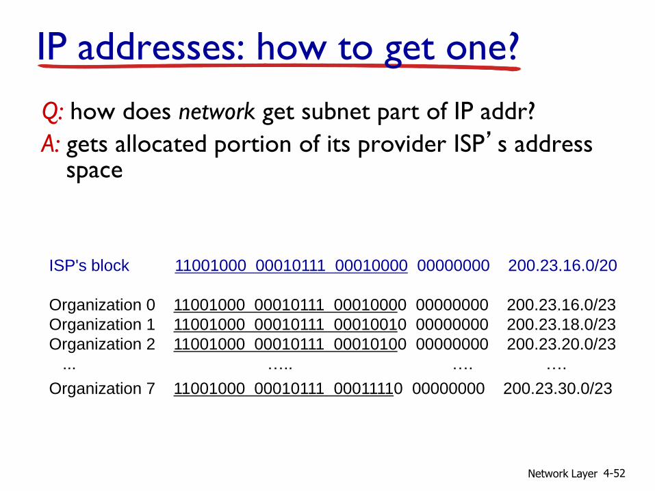
Q: how does network get subnet part of IP addr?
A: gets allocated portion of its provider ISP’s address space
ISP's block 11001000 00010111 00010000 00000000 200.23.16.0/20
Organization 0 11001000 00010111 00010000 00000000 200.23.16.0/23
Organization 1 11001000 00010111 00010010 00000000 200.23.18.0/23
Organization 2 11001000 00010111 00010100 00000000 200.23.20.0/23
... ….. …. ….
Organization 7 11001000 00010111 00011110 00000000 200.23.30.0/23
Network Layer 4-53
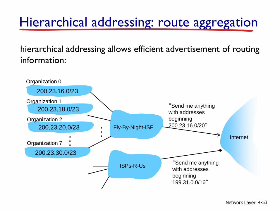
Hierarchical addressing: route aggregation
“Send me anything
with addresses
beginning
200.23.16.0/20”
200.23.16.0/23
200.23.18.0/23
200.23.30.0/23
Fly-By-Night-ISP
Organization 0
Organization 7 Internet
Organization 1
ISPs-R-Us “Send me anything
with addresses
beginning
199.31.0.0/16”
200.23.20.0/23
Organization 2
.
.
.
.
.
.
hierarchical addressing allows efficient advertisement of routing
information:

Network Layer 4-54
ISPs-R-Us has a more specific route to Organization 1
“Send me anything
with addresses
beginning
200.23.16.0/20”
200.23.16.0/23
200.23.18.0/23
200.23.30.0/23
Fly-By-Night-ISP
Organization 0
Organization 7 Internet
Organization 1
ISPs-R-Us “Send me anything
with addresses
beginning 199.31.0.0/16
or 200.23.18.0/23”
200.23.20.0/23
Organization 2
.
.
.
.
.
.
Hierarchical addressing: more specific routes
Network Layer 4-55
IP addressing: the last word...
Q: how does an ISP get block of addresses?
A: ICANN: Internet Corporation for Assigned
Names and Numbers http://www.icann.org/
allocates addresses
manages DNS
assigns domain names, resolves disputes
Network Layer 4-56
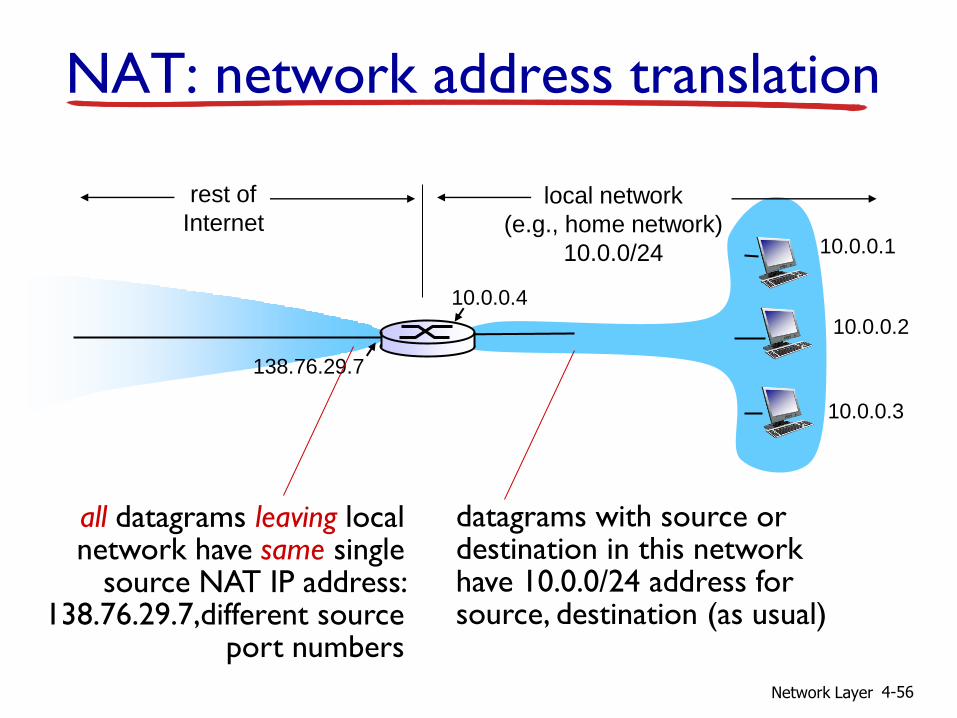
NAT: network address translation
10.0.0.1
10.0.0.2
10.0.0.3
10.0.0.4
138.76.29.7
local network
(e.g., home network)
10.0.0/24
rest of
Internet
datagrams with source or destination in this network have 10.0.0/24 address for source, destination (as usual)
all datagrams leaving local network have same single
source NAT IP address: 138.76.29.7,different source
port numbers

Network Layer 4-57
motivation: local network uses just one IP address as far as outside world is concerned:
range of addresses not needed from ISP: just one IP address for all devices
can change addresses of devices in local network without notifying outside world
can change ISP without changing addresses of devices in local network
devices inside local net not explicitly addressable, visible by outside world (a security plus)
NAT: network address translation

Network Layer 4-58
implementation: NAT router must: outgoing datagrams: replace (source IP address, port #) of
every outgoing datagram to (NAT IP address, new port #)
. . . remote clients/servers will respond using (NAT IP address, new port #) as destination addr
remember (in NAT translation table) every (source IP address, port #) to (NAT IP address, new port #) translation pair
incoming datagrams: replace (NAT IP address, new port #) in dest fields of every incoming datagram with corresponding (source IP address, port #) stored in NAT table
NAT: network address translation
Network Layer 4-59
10.0.0.1
10.0.0.2
10.0.0.3
S: 10.0.0.1, 3345
D: 128.119.40.186, 80
1
10.0.0.4
138.76.29.7
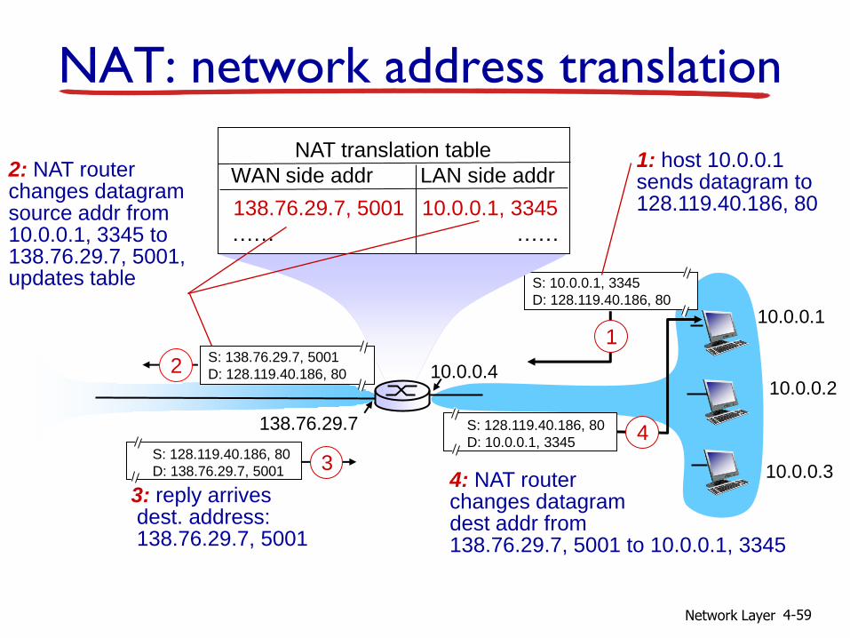
1: host 10.0.0.1 sends datagram to 128.119.40.186, 80
NAT translation table
WAN side addr LAN side addr
138.76.29.7, 5001 10.0.0.1, 3345
…… ……
S: 128.119.40.186, 80
D: 10.0.0.1, 3345
4
S: 138.76.29.7, 5001
D: 128.119.40.186, 80 2
2: NAT router changes datagram source addr from 10.0.0.1, 3345 to 138.76.29.7, 5001, updates table
S: 128.119.40.186, 80
D: 138.76.29.7, 5001
3
3: reply arrives dest. address: 138.76.29.7, 5001
4: NAT router changes datagram dest addr from 138.76.29.7, 5001 to 10.0.0.1, 3345
NAT: network address translation

Network Layer 4-60
16-bit port-number field:
60,000 simultaneous connections with a single LAN-side address!
NAT is controversial:
routers should only process up to layer 3
violates end-to-end argument
• NAT possibility must be taken into account by app
designers, e.g., P2P applications
address shortage should instead be solved by IPv6
NAT: network address translation

Network Layer 4-61
NAT traversal problem
client wants to connect to server with address 10.0.0.1 server address 10.0.0.1 local to
LAN (client can’t use it as destination addr)
only one externally visible NATed address: 138.76.29.7
solution1: statically configure NAT to forward incoming connection requests at given port to server e.g., (123.76.29.7, port 2500)
always forwarded to 10.0.0.1 port 25000
10.0.0.1
10.0.0.4
NAT router
138.76.29.7
client
?
Network Layer 4-62
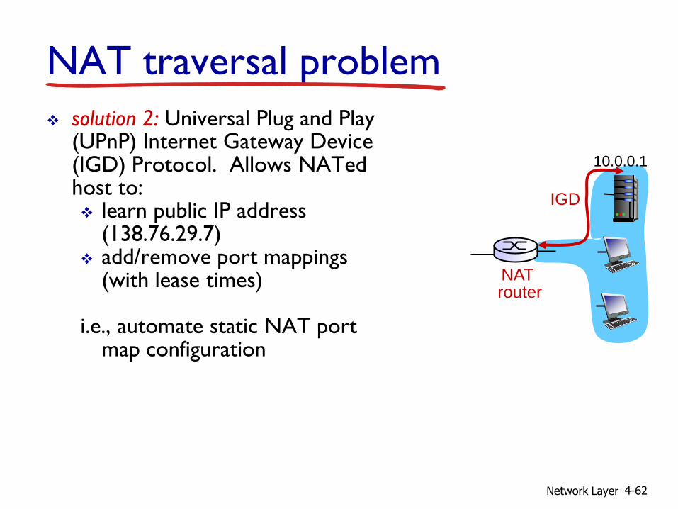
NAT traversal problem
solution 2: Universal Plug and Play (UPnP) Internet Gateway Device (IGD) Protocol. Allows NATed host to: learn public IP address
(138.76.29.7) add/remove port mappings
(with lease times)
i.e., automate static NAT port map configuration
10.0.0.1
NAT router
IGD

Network Layer 4-63
NAT traversal problem
solution 3: relaying (used in Skype)
NATed client establishes connection to relay
external client connects to relay
relay bridges packets between to connections
138.76.29.7
client
1. connection to relay initiated by NATed host
2. connection to relay initiated by client
3. relaying established
NAT router
10.0.0.1

Network Layer 4-64
4.1 introduction
4.2 virtual circuit and datagram networks
4.3 what’s inside a router
4.4 IP: Internet Protocol datagram format
IPv4 addressing
ICMP
IPv6
4.5 routing algorithms link state
distance vector
hierarchical routing
4.6 routing in the Internet RIP
OSPF
BGP
4.7 broadcast and multicast routing
Chapter 4: outline

Network Layer 4-65
ICMP: internet control message protocol
used by hosts & routers to communicate network-level information error reporting:
unreachable host, network, port, protocol
echo request/reply (used by ping)
network-layer “above” IP: ICMP msgs carried in IP
datagrams
ICMP message: type, code plus first 8 bytes of IP datagram causing error
Type Code description
0 0 echo reply (ping)
3 0 dest. network unreachable
3 1 dest host unreachable
3 2 dest protocol unreachable
3 3 dest port unreachable
3 6 dest network unknown
3 7 dest host unknown
4 0 source quench (congestion
control - not used)
8 0 echo request (ping)
9 0 route advertisement
10 0 router discovery
11 0 TTL expired
12 0 bad IP header

Network Layer 4-66
Traceroute and ICMP
source sends series of UDP segments to dest first set has TTL =1
second set has TTL=2, etc.
unlikely port number
when nth set of datagrams arrives to nth router: router discards datagrams
and sends source ICMP messages (type 11, code 0)
ICMP messages includes name of router & IP address
when ICMP messages arrives, source records RTTs
stopping criteria:
UDP segment eventually arrives at destination host
destination returns ICMP “port unreachable” message (type 3, code 3)
source stops
3 probes
3 probes
3 probes

Network Layer 4-67
IPv6: motivation
initial motivation: 32-bit address space soon to be completely allocated.
additional motivation: header format helps speed processing/forwarding
header changes to facilitate QoS
IPv6 datagram format: fixed-length 40 byte header
no fragmentation allowed

Network Layer 4-68
IPv6 datagram format
priority: identify priority among datagrams in flow
flow Label: identify datagrams in same “flow.”
(concept of“flow” not well defined).
next header: identify upper layer protocol for data
data
destination address (128 bits)
source address (128 bits)
payload len next hdr hop limit
flow label pri ver
32 bits

Network Layer 4-69
Other changes from IPv4
checksum: removed entirely to reduce processing time at each hop
options: allowed, but outside of header, indicated by “Next Header” field
ICMPv6: new version of ICMP additional message types, e.g. “Packet Too Big”
multicast group management functions
Network Layer 4-70
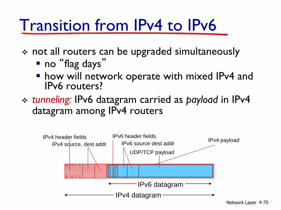
Transition from IPv4 to IPv6
not all routers can be upgraded simultaneously no “flag days” how will network operate with mixed IPv4 and
IPv6 routers?
tunneling: IPv6 datagram carried as payload in IPv4 datagram among IPv4 routers
IPv4 source, dest addr
IPv4 header fields
IPv4 datagram
IPv6 datagram
IPv4 payload
UDP/TCP payload
IPv6 source dest addr
IPv6 header fields

Network Layer 4-71
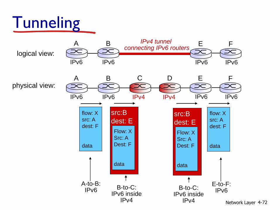
Tunneling
physical view:
IPv4 IPv4
A B
IPv6 IPv6
E
IPv6 IPv6
F C D
logical view:
IPv4 tunnel connecting IPv6 routers
E
IPv6 IPv6
F A B
IPv6 IPv6
Network Layer 4-72
flow: X
src: A
dest: F
data
A-to-B: IPv6
Flow: X
Src: A
Dest: F
data
src:B
dest: E
B-to-C: IPv6 inside
IPv4
E-to-F: IPv6
flow: X
src: A
dest: F
data
B-to-C: IPv6 inside
IPv4
Flow: X
Src: A
Dest: F
data
src:B
dest: E
physical view: A B
IPv6 IPv6
E
IPv6 IPv6
F C D
logical view:
IPv4 tunnel connecting IPv6 routers
E
IPv6 IPv6
F A B
IPv6 IPv6
Tunneling
IPv4 IPv4
Network Layer 4-73
4.1 introduction
4.2 virtual circuit and datagram networks
4.3 what’s inside a router
4.4 IP: Internet Protocol datagram format
IPv4 addressing
ICMP
IPv6
4.5 routing algorithms link state
distance vector
hierarchical routing
4.6 routing in the Internet RIP
OSPF
BGP
4.7 broadcast and multicast routing
Chapter 4: outline

Network Layer 4-74
1
2 3
IP destination address in
arriving packet’s header
routing algorithm
local forwarding table
dest address output link
address-range 1
address-range 2
address-range 3
address-range 4
3
2
2
1
Interplay between routing, forwarding
routing algorithm determines
end-end-path through network
forwarding table determines
local forwarding at this router

Network Layer 4-75
u
y x
w v
z 2
2 1
3
1
1
2
5 3
5
graph: G = (N,E)
N = set of routers = { u, v, w, x, y, z }
E = set of links ={ (u,v), (u,x), (v,x), (v,w), (x,w), (x,y), (w,y), (w,z), (y,z) }
Graph abstraction
aside: graph abstraction is useful in other network contexts, e.g.,
P2P, where N is set of peers and E is set of TCP connections

Network Layer 4-76
Graph abstraction: costs
u
y x
w v
z 2
2 1
3
1
1
2
5 3
5 c(x,x’) = cost of link (x,x’)
e.g., c(w,z) = 5
cost could always be 1, or
inversely related to bandwidth,
or inversely related to
congestion
cost of path (x1, x2, x3,…, xp) = c(x1,x2) + c(x2,x3) + … + c(xp-1,xp)
key question: what is the least-cost path between u and z ?
routing algorithm: algorithm that finds that least cost path
Network Layer 4-77
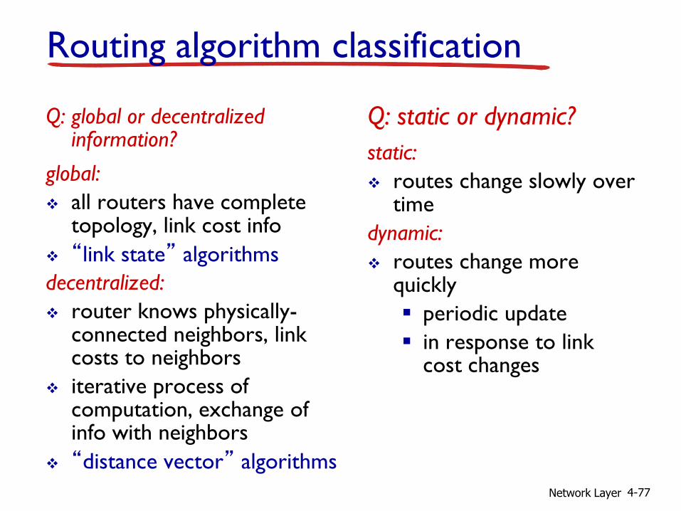
Routing algorithm classification
Q: global or decentralized information?
global:
all routers have complete topology, link cost info
“link state” algorithms
decentralized:
router knows physically-connected neighbors, link costs to neighbors
iterative process of computation, exchange of info with neighbors
“distance vector” algorithms
Q: static or dynamic?
static:
routes change slowly over time
dynamic:
routes change more quickly
periodic update
in response to link cost changes
Network Layer 4-78
4.1 introduction
4.2 virtual circuit and datagram networks
4.3 what’s inside a router
4.4 IP: Internet Protocol datagram format
IPv4 addressing
ICMP
IPv6
4.5 routing algorithms link state
distance vector
hierarchical routing
4.6 routing in the Internet RIP
OSPF
BGP
4.7 broadcast and multicast routing
Chapter 4: outline

Network Layer 4-79
A Link-State Routing Algorithm
Dijkstra’s algorithm net topology, link costs
known to all nodes accomplished via “link state
broadcast”
all nodes have same info
computes least cost paths from one node (‘source”) to all other nodes gives forwarding table for
that node
iterative: after k iterations, know least cost path to k dest.’s
notation: c(x,y): link cost from
node x to y; = ∞ if not direct neighbors
D(v): current value of cost of path from source to dest. v
p(v): predecessor node along path from source to v
N': set of nodes whose least cost path definitively known

Network Layer 4-80
Dijsktra’s Algorithm
1 Initialization:
2 N' = {u}
3 for all nodes v
4 if v adjacent to u
5 then D(v) = c(u,v)
6 else D(v) = ∞
7
8 Loop
9 find w not in N' such that D(w) is a minimum
10 add w to N'
11 update D(v) for all v adjacent to w and not in N' :
12 D(v) = min( D(v), D(w) + c(w,v) )
13 /* new cost to v is either old cost to v or known
14 shortest path cost to w plus cost from w to v */
15 until all nodes in N'
Network Layer 4-81
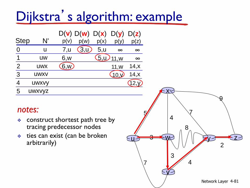
w 3
4
v
x
u
5
3 7 4
y
8
z 2
7
9
Dijkstra’s algorithm: example
Step
N' D(v)
p(v)
0
1
2
3
4
5
D(w) p(w)
D(x) p(x)
D(y) p(y)
D(z) p(z)
u ∞ ∞ 7,u 3,u 5,u
uw ∞ 11,w 6,w 5,u
14,x 11,w 6,w uwx
uwxv 14,x 10,v uwxvy 12,y
notes: construct shortest path tree by
tracing predecessor nodes
ties can exist (can be broken arbitrarily)
uwxvyz
Network Layer 4-82
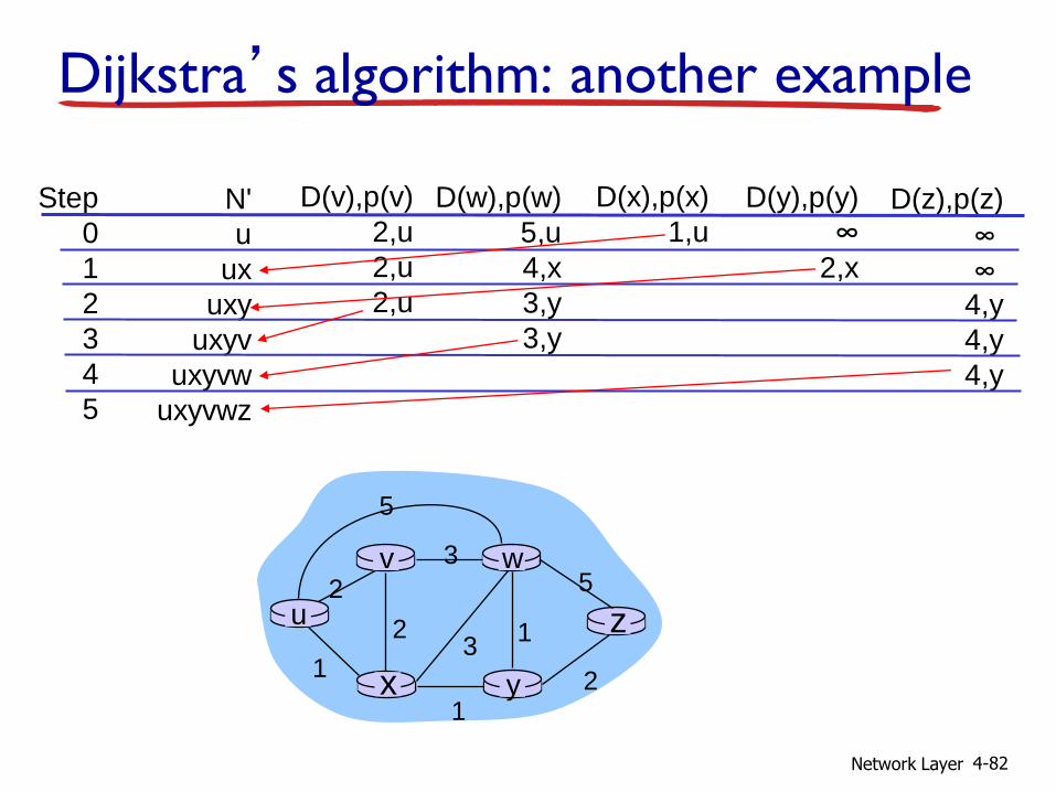
Dijkstra’s algorithm: another example
Step
0
1
2
3
4
5
N'
u
ux
uxy
uxyv
uxyvw
uxyvwz
D(v),p(v)
2,u
2,u
2,u
D(w),p(w)
5,u
4,x
3,y
3,y
D(x),p(x)
1,u
D(y),p(y)
∞ 2,x
D(z),p(z)
∞ ∞
4,y
4,y
4,y
u
y x
w v
z 2
2 1
3
1
1
2
5 3
5
Network Layer 4-83
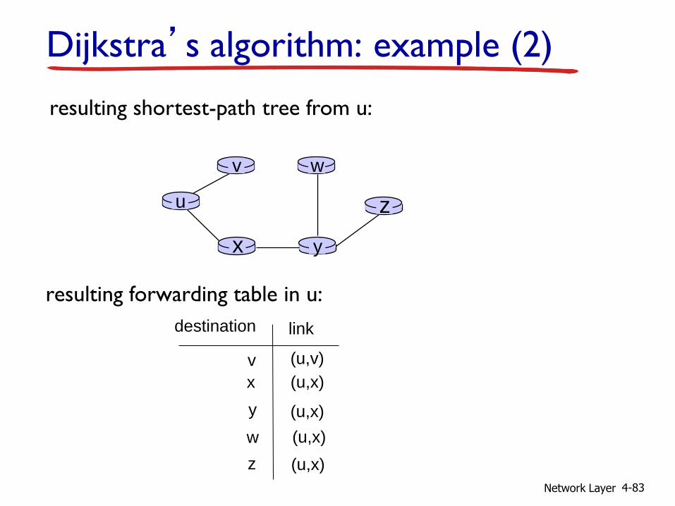
Dijkstra’s algorithm: example (2)
u
y x
w v
z
resulting shortest-path tree from u:
v
x
y
w
z
(u,v)
(u,x)
(u,x)
(u,x)
(u,x)
destination link
resulting forwarding table in u:

Network Layer 4-84
Dijkstra’s algorithm, discussion
algorithm complexity: n nodes
each iteration: need to check all nodes, w, not in N
n(n+1)/2 comparisons: O(n2)
more efficient implementations possible: O(nlogn)
oscillations possible:
e.g., support link cost equals amount of carried traffic:
A
D
C
B
1 1+e
e 0
e
1 1
0 0
initially
A
D
C
B
given these costs, find new routing….
resulting in new costs
2+e 0
0 0
1+e 1
A
D
C
B
given these costs, find new routing….
resulting in new costs
0 2+e
1+e 1
0 0
A
D
C
B
given these costs, find new routing….
resulting in new costs
2+e 0
0 0
1+e 1

Network Layer 4-85
4.1 introduction
4.2 virtual circuit and datagram networks
4.3 what’s inside a router
4.4 IP: Internet Protocol datagram format
IPv4 addressing
ICMP
IPv6
4.5 routing algorithms link state
distance vector
hierarchical routing
4.6 routing in the Internet RIP
OSPF
BGP
4.7 broadcast and multicast routing
Chapter 4: outline

Network Layer 4-86
Distance vector algorithm
Bellman-Ford equation (dynamic programming)
let
dx(y) := cost of least-cost path from x to y
then
dx(y) = min {c(x,v) + dv(y) }
v
cost to neighbor v
min taken over all neighbors v of x
cost from neighbor v to destination y
Network Layer 4-87
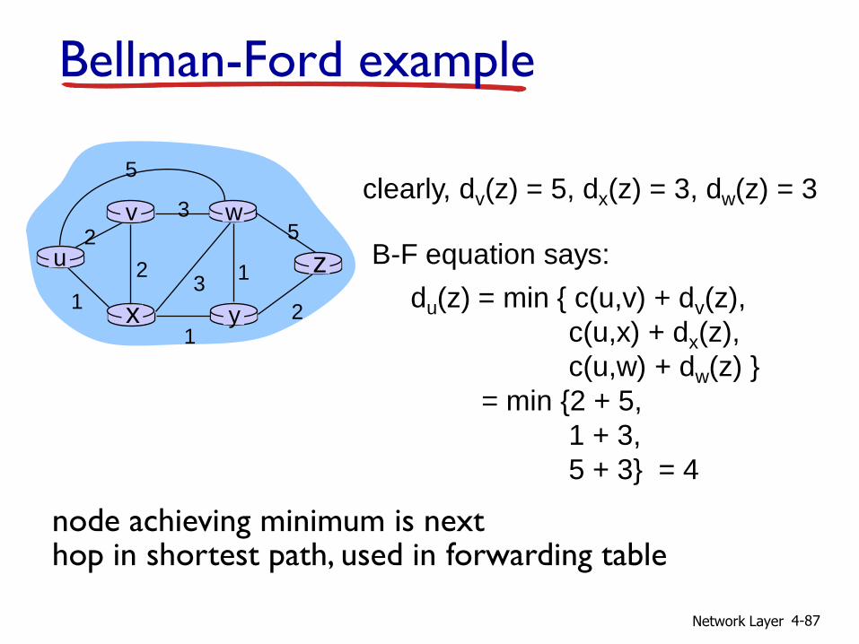
Bellman-Ford example
u
y x
w v
z 2
2 1
3
1
1
2
5 3
5 clearly, dv(z) = 5, dx(z) = 3, dw(z) = 3
du(z) = min { c(u,v) + dv(z),
c(u,x) + dx(z),
c(u,w) + dw(z) }
= min {2 + 5,
1 + 3,
5 + 3} = 4
node achieving minimum is next hop in shortest path, used in forwarding table
B-F equation says:
Network Layer 4-88
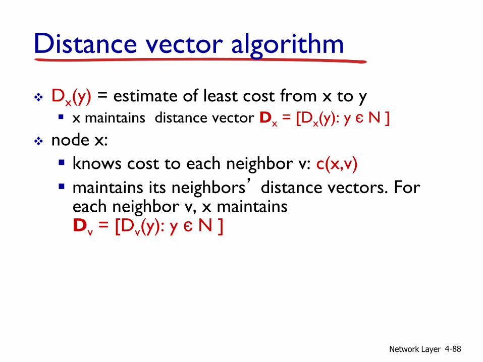
Distance vector algorithm
Dx(y) = estimate of least cost from x to y x maintains distance vector Dx = [Dx(y): y є N ]
node x:
knows cost to each neighbor v: c(x,v)
maintains its neighbors’ distance vectors. For each neighbor v, x maintains Dv = [Dv(y): y є N ]
Network Layer 4-89
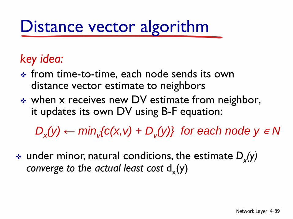
key idea: from time-to-time, each node sends its own
distance vector estimate to neighbors
when x receives new DV estimate from neighbor, it updates its own DV using B-F equation:
Dx(y) ← minv{c(x,v) + Dv(y)} for each node y ∊ N
under minor, natural conditions, the estimate Dx(y) converge to the actual least cost dx(y)
Distance vector algorithm

Network Layer 4-90
iterative, asynchronous: each local iteration caused by:
local link cost change
DV update message from neighbor
distributed: each node notifies
neighbors only when its DV changes neighbors then notify their
neighbors if necessary
wait for (change in local link
cost or msg from neighbor)
recompute estimates
if DV to any dest has
changed, notify neighbors
each node:
Distance vector algorithm
Network Layer 4-91
x y z
x
y
z
0 2 7
∞ ∞ ∞
∞ ∞ ∞
from
cost to
from
fr
om
x y z
x
y
z
0
x y z
x
y
z
∞ ∞
∞ ∞ ∞
cost to
x y z
x
y
z ∞ ∞ ∞
7 1 0
cost to
∞
2 0 1
∞ ∞ ∞
2 0 1
7 1 0
time
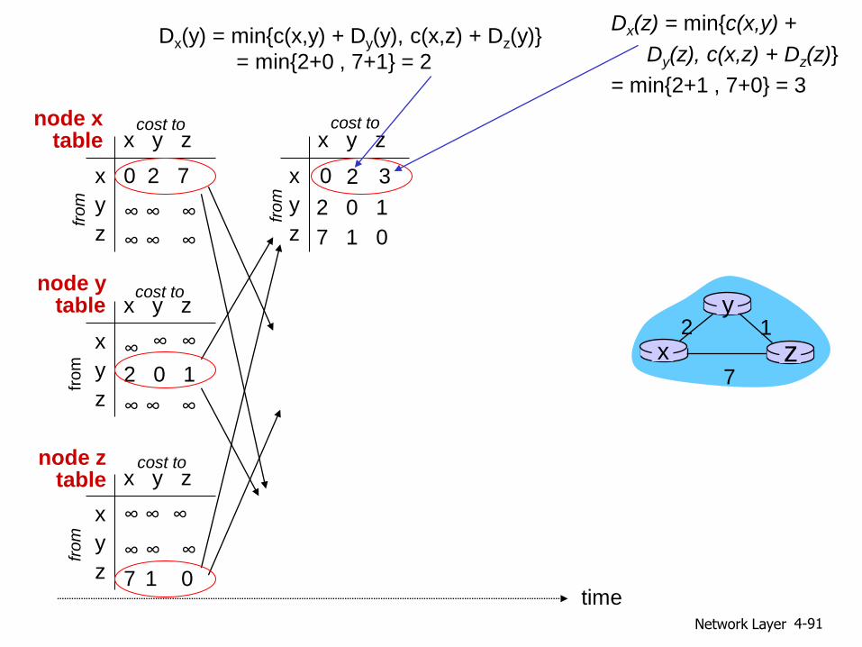
x z 1 2
7
y
node x table
Dx(y) = min{c(x,y) + Dy(y), c(x,z) + Dz(y)}
= min{2+0 , 7+1} = 2
Dx(z) = min{c(x,y) +
Dy(z), c(x,z) + Dz(z)}
= min{2+1 , 7+0} = 3
3 2
node y table
node z table
cost to
from

Network Layer 4-92
x y z
x
y
z
0 2 3
from
cost to
x y z
x
y
z
0 2 7
from
cost to
x y z
x
y
z
0 2 3
from
cost to
x y z
x
y
z
0 2 3
from
cost to
x y z
x
y
z
0 2 7
from
cost to
2 0 1
7 1 0
2 0 1
3 1 0
2 0 1
3 1 0
2 0 1
3 1 0
2 0 1
3 1 0
time
x y z
x
y
z
0 2 7
∞ ∞ ∞
∞ ∞ ∞
from
cost to
from
fr
om
x y z
x
y
z
0
x y z
x
y
z
∞ ∞
∞ ∞ ∞
cost to
x y z
x
y
z ∞ ∞ ∞
7 1 0
cost to
∞
2 0 1
∞ ∞ ∞
2 0 1
7 1 0
time
x z 1 2
7
y
node x table
Dx(y) = min{c(x,y) + Dy(y), c(x,z) + Dz(y)}
= min{2+0 , 7+1} = 2
Dx(z) = min{c(x,y) +
Dy(z), c(x,z) + Dz(z)}
= min{2+1 , 7+0} = 3
3 2
node y table
node z table
cost to
from
Network Layer 4-93
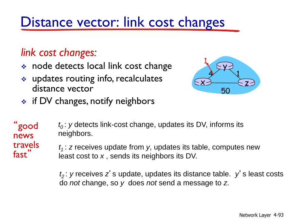
Distance vector: link cost changes
link cost changes: node detects local link cost change
updates routing info, recalculates distance vector
if DV changes, notify neighbors
“good news travels fast”
x z 1 4
50
y 1
t0 : y detects link-cost change, updates its DV, informs its
neighbors.
t1 : z receives update from y, updates its table, computes new
least cost to x , sends its neighbors its DV.
t2 : y receives z’s update, updates its distance table. y’s least costs
do not change, so y does not send a message to z.

Network Layer 4-94
Distance vector: link cost changes
link cost changes: node detects local link cost change
bad news travels slow - “count to infinity” problem!
44 iterations before algorithm stabilizes: see text
x z 1 4
50
y 60
poisoned reverse: If Z routes through Y to get to X :
Z tells Y its (Z’s) distance to X is infinite (so Y won’t route to X via Z)
will this completely solve count to infinity problem?
Network Layer 4-95
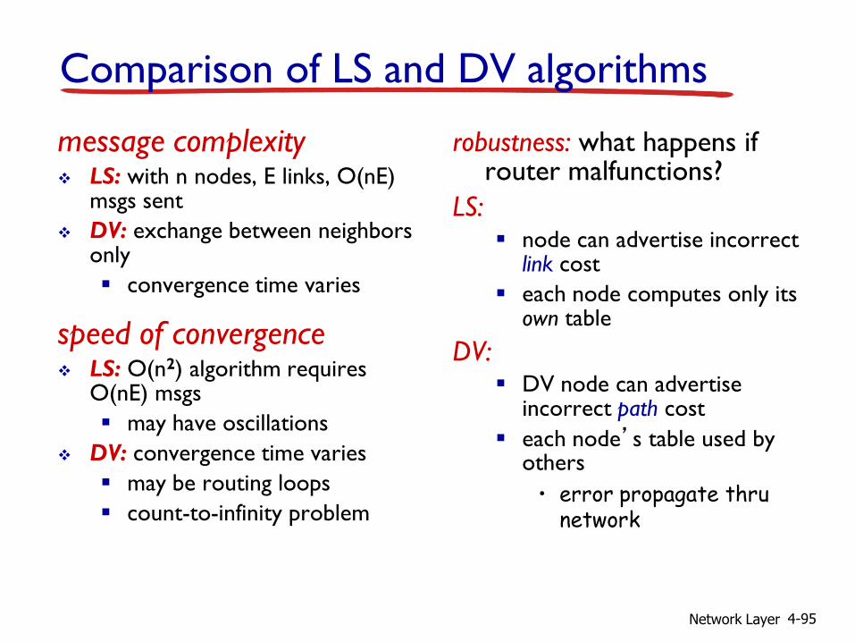
Comparison of LS and DV algorithms
message complexity LS: with n nodes, E links, O(nE)
msgs sent
DV: exchange between neighbors only
convergence time varies
speed of convergence LS: O(n2) algorithm requires
O(nE) msgs
may have oscillations
DV: convergence time varies
may be routing loops
count-to-infinity problem
robustness: what happens if router malfunctions?
LS: node can advertise incorrect
link cost
each node computes only its own table
DV: DV node can advertise
incorrect path cost
each node’s table used by others
• error propagate thru network
Network Layer 4-96
4.1 introduction
4.2 virtual circuit and datagram networks
4.3 what’s inside a router
4.4 IP: Internet Protocol datagram format
IPv4 addressing
ICMP
IPv6
4.5 routing algorithms link state
distance vector
hierarchical routing
4.6 routing in the Internet RIP
OSPF
BGP
4.7 broadcast and multicast routing
Chapter 4: outline

Network Layer 4-97
Hierarchical routing
scale: with 600 million destinations:
can’t store all dest’s in routing tables!
routing table exchange would swamp links!
administrative autonomy internet = network of
networks
each network admin may want to control routing in its own network
our routing study thus far - idealization
all routers identical
network “flat”
… not true in practice
Network Layer 4-98
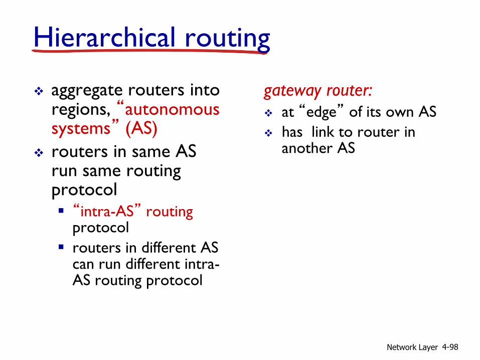
aggregate routers into regions, “autonomous systems” (AS)
routers in same AS run same routing protocol “intra-AS” routing
protocol
routers in different AS can run different intra-AS routing protocol
gateway router: at “edge” of its own AS
has link to router in another AS
Hierarchical routing

Network Layer 4-99
3b
1d
3a
1c 2a
AS3
AS1
AS2 1a
2c
2b
1b
Intra-AS
Routing
algorithm
Inter-AS
Routing
algorithm
Forwarding
table
3c
Interconnected ASes
forwarding table configured by both intra- and inter-AS routing algorithm
intra-AS sets entries for internal dests
inter-AS & intra-AS sets entries for external dests
Network Layer 4-100
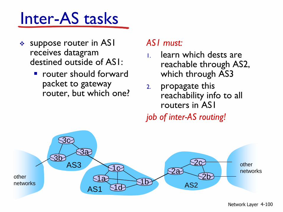
Inter-AS tasks
suppose router in AS1 receives datagram destined outside of AS1:
router should forward packet to gateway router, but which one?
AS1 must:
1. learn which dests are reachable through AS2, which through AS3
2. propagate this reachability info to all routers in AS1
job of inter-AS routing!
AS3
AS2
3b
3c
3a
AS1
1c
1a 1d
1b
2a 2c
2b
other
networks other
networks
Network Layer 4-101
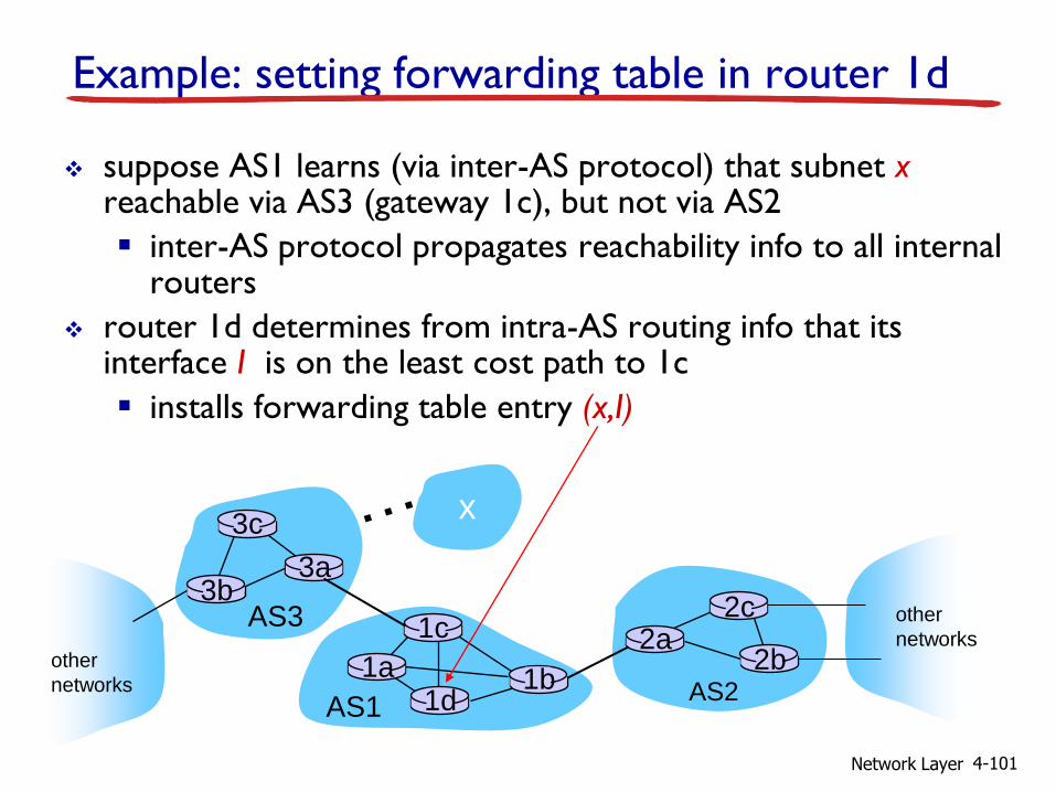
Example: setting forwarding table in router 1d
suppose AS1 learns (via inter-AS protocol) that subnet x reachable via AS3 (gateway 1c), but not via AS2
inter-AS protocol propagates reachability info to all internal routers
router 1d determines from intra-AS routing info that its interface I is on the least cost path to 1c
installs forwarding table entry (x,I)
AS3
AS2
3b
3c
3a
AS1
1c
1a 1d
1b
2a 2c
2b
other
networks other
networks
x
Network Layer 4-102
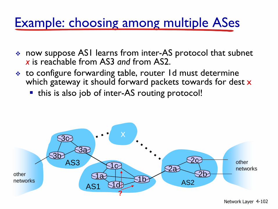
Example: choosing among multiple ASes
now suppose AS1 learns from inter-AS protocol that subnet x is reachable from AS3 and from AS2.
to configure forwarding table, router 1d must determine which gateway it should forward packets towards for dest x
this is also job of inter-AS routing protocol!
AS3
AS2
3b
3c
3a
AS1
1c
1a 1d
1b
2a 2c
2b
other
networks other
networks
x
?

Network Layer 4-103
learn from inter-AS
protocol that subnet
x is reachable via
multiple gateways
use routing info
from intra-AS
protocol to determine
costs of least-cost
paths to each
of the gateways
hot potato routing:
choose the gateway
that has the
smallest least cost
determine from
forwarding table the
interface I that leads
to least-cost gateway.
Enter (x,I) in
forwarding table
Example: choosing among multiple ASes
now suppose AS1 learns from inter-AS protocol that subnet x is reachable from AS3 and from AS2.
to configure forwarding table, router 1d must determine towards which gateway it should forward packets for dest x
this is also job of inter-AS routing protocol!
hot potato routing: send packet towards closest of two routers.
Network Layer 4-104
4.1 introduction
4.2 virtual circuit and datagram networks
4.3 what’s inside a router
4.4 IP: Internet Protocol datagram format
IPv4 addressing
ICMP
IPv6
4.5 routing algorithms link state
distance vector
hierarchical routing
4.6 routing in the Internet RIP
OSPF
BGP
4.7 broadcast and multicast routing
Chapter 4: outline

Network Layer 4-105
Intra-AS Routing
also known as interior gateway protocols (IGP)
most common intra-AS routing protocols:
RIP: Routing Information Protocol
OSPF: Open Shortest Path First
IGRP: Interior Gateway Routing Protocol (Cisco proprietary)
Network Layer 4-106
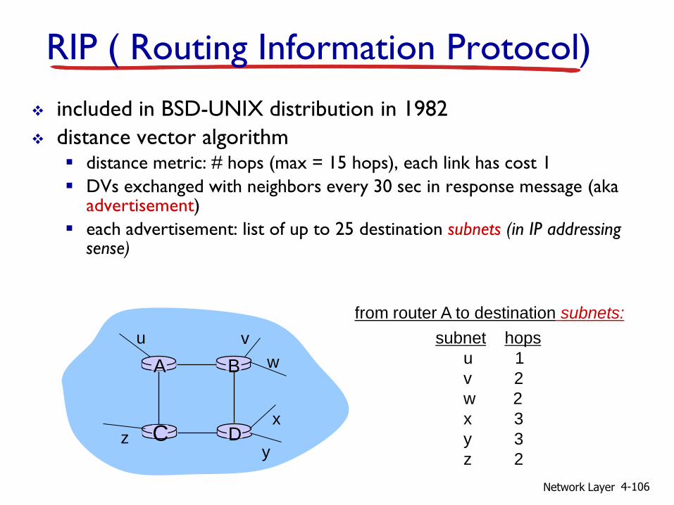
RIP ( Routing Information Protocol)
included in BSD-UNIX distribution in 1982
distance vector algorithm distance metric: # hops (max = 15 hops), each link has cost 1
DVs exchanged with neighbors every 30 sec in response message (aka advertisement)
each advertisement: list of up to 25 destination subnets (in IP addressing sense)
D C
B A
u v
w
x
y z
subnet hops
u 1
v 2
w 2
x 3
y 3
z 2
from router A to destination subnets:
Network Layer 4-107
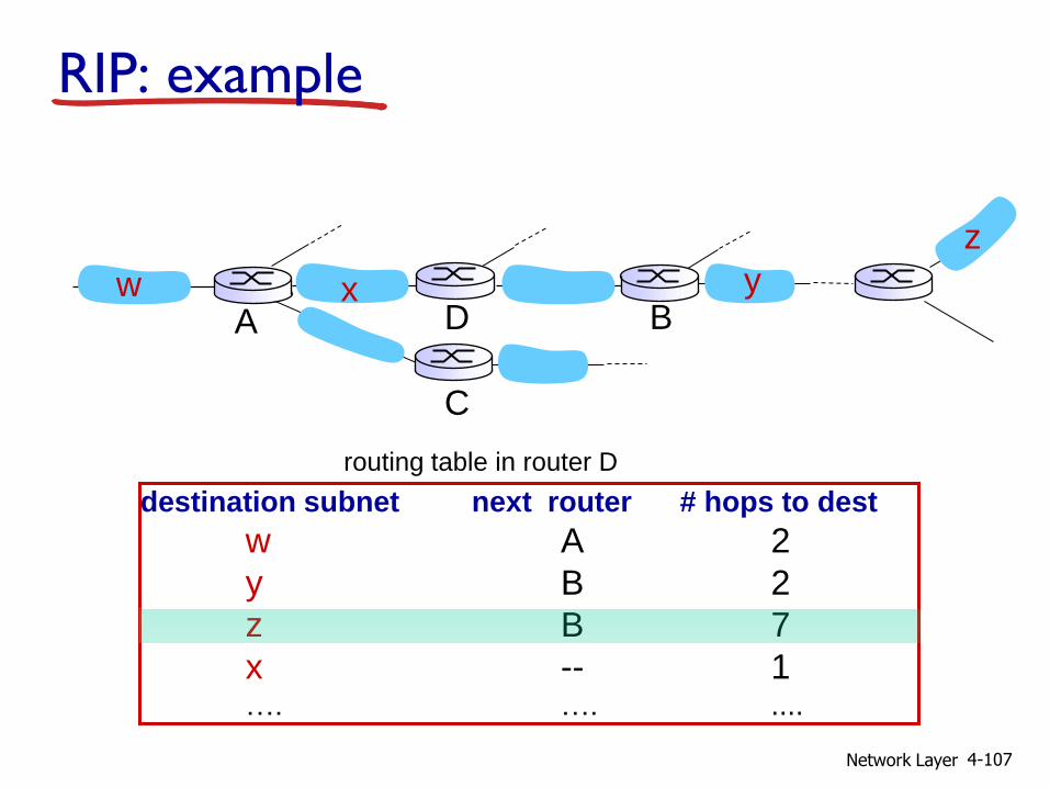
RIP: example
destination subnet next router # hops to dest
w A 2
y B 2
z B 7
x -- 1 …. …. ....
routing table in router D
w x y
z
A
C
D B
Network Layer 4-108
w x y
z
A
C
D B
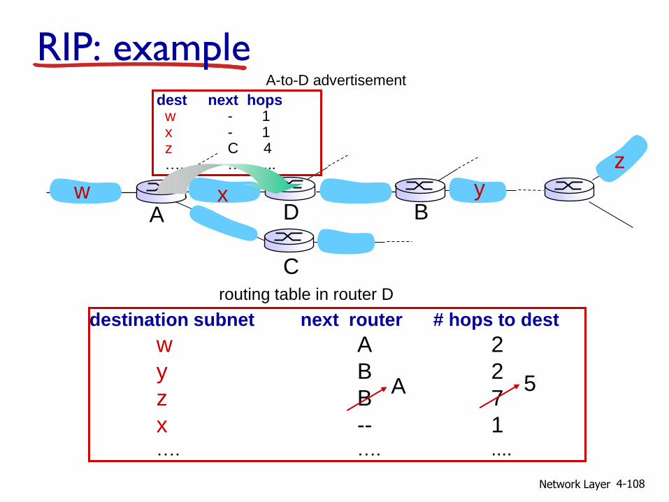
destination subnet next router # hops to dest
w A 2
y B 2
z B 7
x -- 1 …. …. ....
routing table in router D
A 5
dest next hops w - 1 x - 1 z C 4 …. … ...
A-to-D advertisement
RIP: example
Network Layer 4-109
RIP: link failure, recovery
if no advertisement heard after 180 sec --> neighbor/link declared dead routes via neighbor invalidated
new advertisements sent to neighbors
neighbors in turn send out new advertisements (if tables changed)
link failure info quickly (?) propagates to entire net
poison reverse used to prevent ping-pong loops (infinite distance = 16 hops)

Network Layer 4-110
RIP table processing
RIP routing tables managed by application-level process called route-d (daemon)
advertisements sent in UDP packets, periodically repeated
physical
link
network forwarding
(IP) table
transport
(UDP)
routed
physical
link
network
(IP)
transprt
(UDP)
routed
forwarding
table

Network Layer 4-111
OSPF (Open Shortest Path First)
“open”: publicly available
uses link state algorithm LS packet dissemination
topology map at each node
route computation using Dijkstra’s algorithm
OSPF advertisement carries one entry per neighbor
advertisements flooded to entire AS carried in OSPF messages directly over IP (rather than
TCP or UDP
IS-IS routing protocol: nearly identical to OSPF
Network Layer 4-112
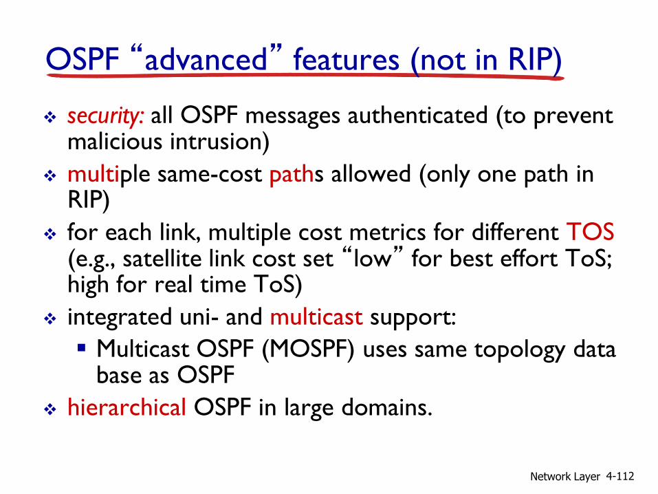
OSPF “advanced” features (not in RIP)
security: all OSPF messages authenticated (to prevent malicious intrusion)
multiple same-cost paths allowed (only one path in RIP)
for each link, multiple cost metrics for different TOS (e.g., satellite link cost set “low” for best effort ToS; high for real time ToS)
integrated uni- and multicast support:
Multicast OSPF (MOSPF) uses same topology data base as OSPF
hierarchical OSPF in large domains.
Network Layer 4-113
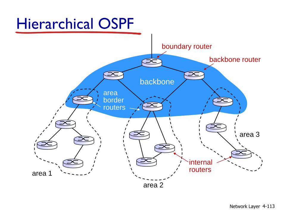
Hierarchical OSPF
boundary router
backbone router
area 1
area 2
area 3
backbone
area border routers
internal routers
Network Layer 4-114
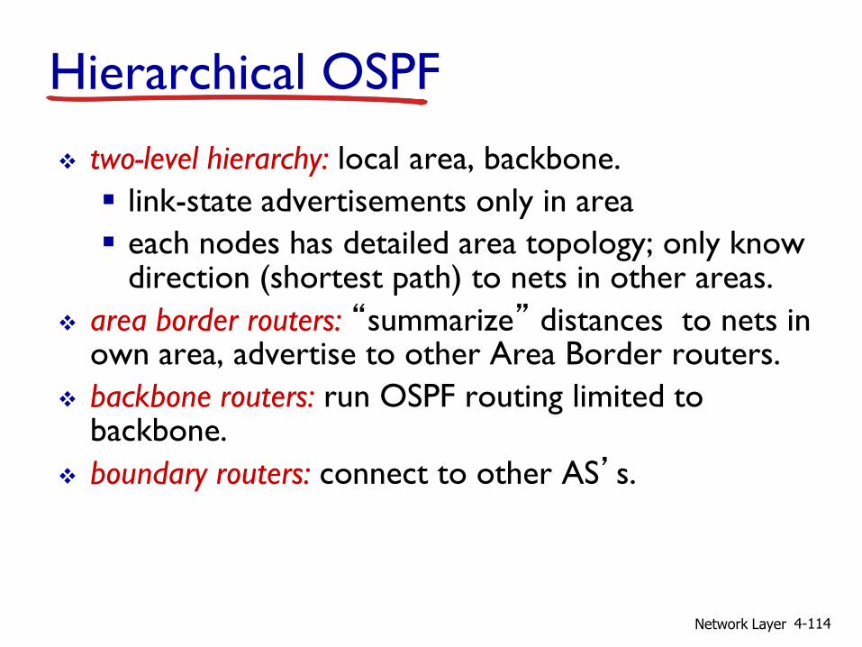
two-level hierarchy: local area, backbone.
link-state advertisements only in area
each nodes has detailed area topology; only know direction (shortest path) to nets in other areas.
area border routers: “summarize” distances to nets in own area, advertise to other Area Border routers.
backbone routers: run OSPF routing limited to backbone.
boundary routers: connect to other AS’s.
Hierarchical OSPF

Network Layer 4-115
Internet inter-AS routing: BGP
BGP (Border Gateway Protocol): the de facto inter-domain routing protocol “glue that holds the Internet together”
BGP provides each AS a means to:
eBGP: obtain subnet reachability information from neighboring ASs.
iBGP: propagate reachability information to all AS-internal routers.
determine “good” routes to other networks based on reachability information and policy.
allows subnet to advertise its existence to rest of Internet: “I am here”
Network Layer 4-116
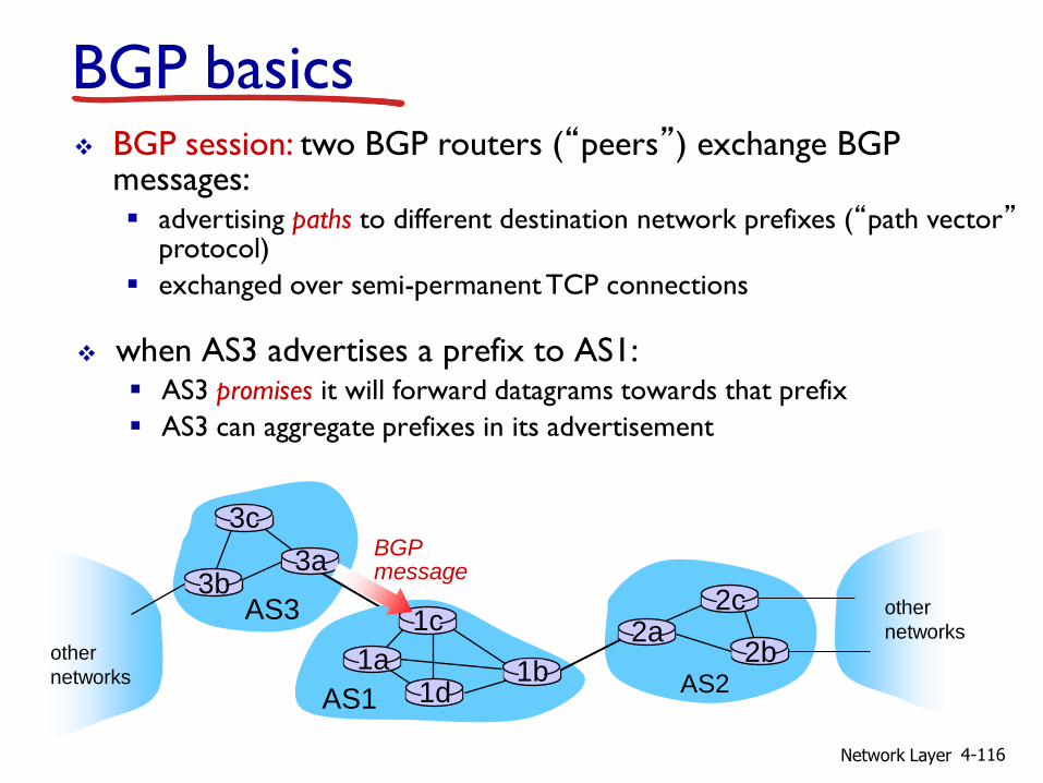
BGP basics
when AS3 advertises a prefix to AS1: AS3 promises it will forward datagrams towards that prefix
AS3 can aggregate prefixes in its advertisement
AS3
AS2
3b
3c
3a
AS1
1c
1a 1d
1b
2a 2c
2b
other
networks other
networks
BGP session: two BGP routers (“peers”) exchange BGP messages: advertising paths to different destination network prefixes (“path vector”
protocol)
exchanged over semi-permanent TCP connections
BGP message

Network Layer 4-117
BGP basics: distributing path information
AS3
AS2
3b 3a
AS1
1c
1a 1d
1b
2a 2c
2b
other
networks other
networks
using eBGP session between 3a and 1c, AS3 sends prefix reachability info to AS1. 1c can then use iBGP do distribute new prefix info to all routers
in AS1
1b can then re-advertise new reachability info to AS2 over 1b-to-2a eBGP session
when router learns of new prefix, it creates entry for prefix in its forwarding table.
eBGP session
iBGP session

Network Layer 4-118
Path attributes and BGP routes
advertised prefix includes BGP attributes prefix + attributes = “route”
two important attributes: AS-PATH: contains ASs through which prefix
advertisement has passed: e.g., AS 67, AS 17
NEXT-HOP: indicates specific internal-AS router to next-hop AS. (may be multiple links from current AS to next-hop-AS)
gateway router receiving route advertisement uses import policy to accept/decline e.g., never route through AS x
policy-based routing

Network Layer 4-119
BGP route selection
router may learn about more than 1 route to destination AS, selects route based on:
1. local preference value attribute: policy decision
2. shortest AS-PATH
3. closest NEXT-HOP router: hot potato routing
4. additional criteria

Network Layer 4-120
BGP messages
BGP messages exchanged between peers over TCP connection
BGP messages:
OPEN: opens TCP connection to peer and authenticates sender
UPDATE: advertises new path (or withdraws old)
KEEPALIVE: keeps connection alive in absence of UPDATES; also ACKs OPEN request
NOTIFICATION: reports errors in previous msg; also used to close connection
Network Layer 4-121
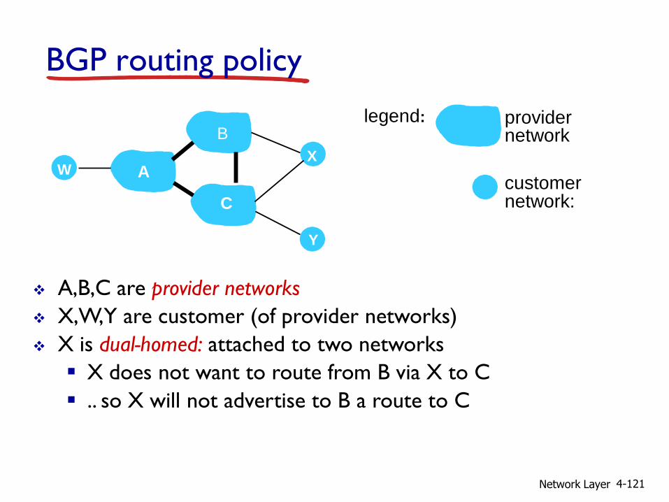
BGP routing policy
A,B,C are provider networks
X,W,Y are customer (of provider networks)
X is dual-homed: attached to two networks
X does not want to route from B via X to C
.. so X will not advertise to B a route to C
A
B
C
W X
Y
legend:
customer network:
provider network

Network Layer 4-122
BGP routing policy (2)
A advertises path AW to B
B advertises path BAW to X
Should B advertise path BAW to C? No way! B gets no “revenue” for routing CBAW since neither W nor
C are B’s customers
B wants to force C to route to w via A
B wants to route only to/from its customers!
A
B
C
W X
Y
legend:
customer network:
provider network
Network Layer 4-123
Why different Intra-, Inter-AS routing ?
policy: inter-AS: admin wants control over how its traffic
routed, who routes through its net.
intra-AS: single admin, so no policy decisions needed
scale: hierarchical routing saves table size, reduced update
traffic
performance:
intra-AS: can focus on performance
inter-AS: policy may dominate over performance

Network Layer 4-124
4.1 introduction
4.2 virtual circuit and datagram networks
4.3 what’s inside a router
4.4 IP: Internet Protocol datagram format
IPv4 addressing
ICMP
IPv6
4.5 routing algorithms link state
distance vector
hierarchical routing
4.6 routing in the Internet RIP
OSPF
BGP
4.7 broadcast and multicast routing
Chapter 4: outline

Network Layer 4-125
R1
R2
R3 R4
source
duplication
R1
R2
R3 R4
in-network
duplication
duplicate
creation/transmission duplicate
duplicate
Broadcast routing deliver packets from source to all other nodes
source duplication is inefficient:
source duplication: how does source determine recipient addresses?

Network Layer 4-126
In-network duplication
flooding: when node receives broadcast packet, sends copy to all neighbors problems: cycles & broadcast storm
controlled flooding: node only broadcasts pkt if it hasn’t broadcast same packet before node keeps track of packet ids already broadacsted
or reverse path forwarding (RPF): only forward packet if it arrived on shortest path between node and source
spanning tree: no redundant packets received by any node

Network Layer 4-127
A
B
G
D
E
c
F
A
B
G
D
E
c
F
(a) broadcast initiated at A (b) broadcast initiated at D
Spanning tree
first construct a spanning tree
nodes then forward/make copies only along spanning tree

Network Layer 4-128
A
B
G
D
E
c
F 1
2
3
4
5
(a) stepwise construction of
spanning tree (center: E)
A
B
G
D
E
c
F
(b) constructed spanning
tree
Spanning tree: creation
center node
each node sends unicast join message to center node message forwarded until it arrives at a node already
belonging to spanning tree
Network Layer 4-129
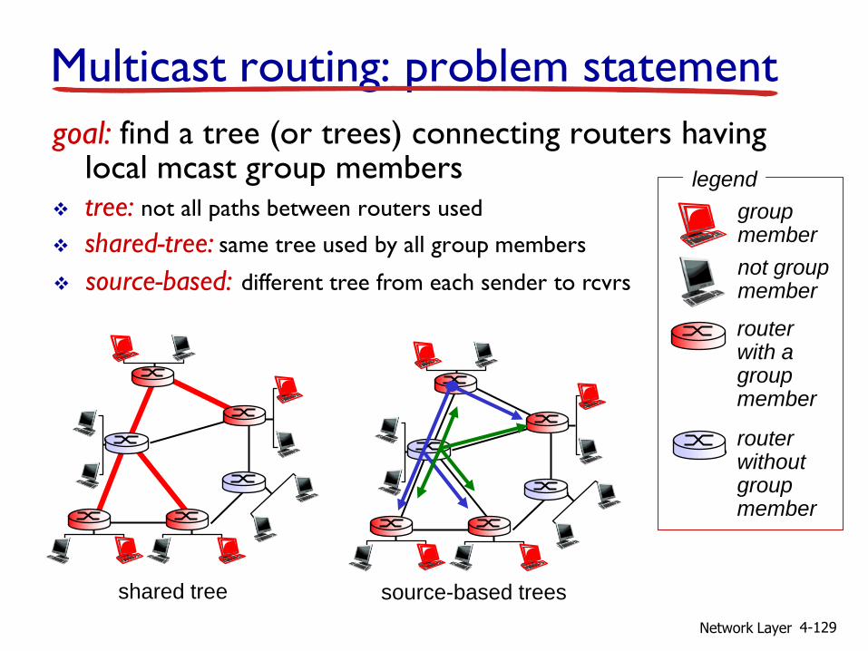
Multicast routing: problem statement
goal: find a tree (or trees) connecting routers having local mcast group members
tree: not all paths between routers used
shared-tree: same tree used by all group members
shared tree source-based trees
group member
not group member
router with a group member
router without group member
legend
source-based: different tree from each sender to rcvrs
Network Layer 4-130
Approaches for building mcast trees
approaches:
source-based tree: one tree per source shortest path trees
reverse path forwarding
group-shared tree: group uses one tree minimal spanning (Steiner)
center-based trees
…we first look at basic approaches, then specific protocols
adopting these approaches

Network Layer 4-131
Shortest path tree
mcast forwarding tree: tree of shortest path routes from source to all receivers Dijkstra’s algorithm
i
router with attached
group member
router with no attached
group member
link used for forwarding,
i indicates order link
added by algorithm
LEGEND
R1
R2
R3
R4
R5
R6 R7
2
1
6
3 4
5
s: source

Network Layer 4-132
Reverse path forwarding
if (mcast datagram received on incoming link on shortest path back to center)
then flood datagram onto all outgoing links
else ignore datagram
rely on router’s knowledge of unicast shortest
path from it to sender
each router has simple forwarding behavior:

Network Layer 4-133
Reverse path forwarding: example
result is a source-specific reverse SPT
may be a bad choice with asymmetric links
router with attached
group member
router with no attached
group member
datagram will be forwarded
LEGEND R1
R2
R3
R4
R5
R6 R7
s: source
datagram will not be
forwarded
Network Layer 4-134
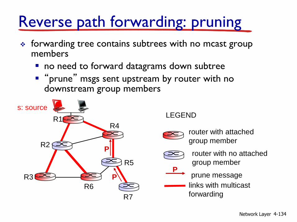
Reverse path forwarding: pruning
forwarding tree contains subtrees with no mcast group members
no need to forward datagrams down subtree
“prune” msgs sent upstream by router with no downstream group members
router with attached
group member
router with no attached
group member
prune message
LEGEND
links with multicast
forwarding
P
R1
R2
R3
R4
R5
R6
R7
s: source
P
P

Network Layer 4-135
Shared-tree: steiner tree
steiner tree: minimum cost tree connecting all routers with attached group members
problem is NP-complete
excellent heuristics exists
not used in practice: computational complexity
information about entire network needed
monolithic: rerun whenever a router needs to join/leave
Network Layer 4-136
Center-based trees
single delivery tree shared by all
one router identified as “center” of tree
to join: edge router sends unicast join-msg addressed to center
router
join-msg “processed” by intermediate routers and forwarded towards center
join-msg either hits existing tree branch for this center, or arrives at center
path taken by join-msg becomes new branch of tree for this router

Network Layer 4-137
Center-based trees: example
suppose R6 chosen as center:
router with attached
group member
router with no attached
group member
path order in which join
messages generated
LEGEND
2 1
3
1
R1
R2
R3
R4
R5
R6
R7
Network Layer 4-138
Internet Multicasting Routing: DVMRP
DVMRP: distance vector multicast routing protocol, RFC1075
flood and prune: reverse path forwarding, source-based tree RPF tree based on DVMRP’s own routing tables
constructed by communicating DVMRP routers
no assumptions about underlying unicast
initial datagram to mcast group flooded everywhere via RPF
routers not wanting group: send upstream prune msgs

Network Layer 4-139
DVMRP: continued…
soft state: DVMRP router periodically (1 min.) “forgets” branches are pruned: mcast data again flows down unpruned branch
downstream router: reprune or else continue to receive data
routers can quickly regraft to tree following IGMP join at leaf
odds and ends commonly implemented in commercial router
Network Layer 4-140
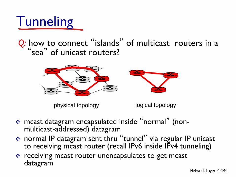
Tunneling
Q: how to connect “islands” of multicast routers in a “sea” of unicast routers?
mcast datagram encapsulated inside “normal” (non-multicast-addressed) datagram
normal IP datagram sent thru “tunnel” via regular IP unicast to receiving mcast router (recall IPv6 inside IPv4 tunneling)
receiving mcast router unencapsulates to get mcast datagram
physical topology logical topology
Network Layer 4-141
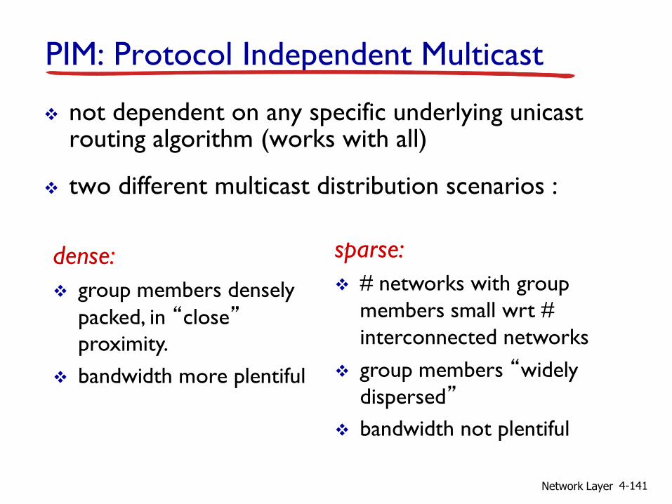
PIM: Protocol Independent Multicast
not dependent on any specific underlying unicast routing algorithm (works with all)
two different multicast distribution scenarios :
dense:
group members densely
packed, in “close”
proximity.
bandwidth more plentiful
sparse:
# networks with group
members small wrt #
interconnected networks
group members “widely
dispersed”
bandwidth not plentiful

Network Layer 4-142
Consequences of sparse-dense dichotomy:
dense group membership by
routers assumed until routers explicitly prune
data-driven construction on mcast tree (e.g., RPF)
bandwidth and non-group-router processing profligate
sparse:
no membership until routers explicitly join
receiver- driven construction of mcast tree (e.g., center-based)
bandwidth and non-group-router processing conservative

Network Layer 4-143
PIM- dense mode
flood-and-prune RPF: similar to DVMRP but…
underlying unicast protocol provides RPF info for incoming datagram
less complicated (less efficient) downstream flood than DVMRP reduces reliance on underlying routing algorithm
has protocol mechanism for router to detect it is a leaf-node router
Network Layer 4-144
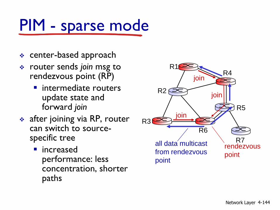
PIM - sparse mode
center-based approach
router sends join msg to rendezvous point (RP)
intermediate routers update state and forward join
after joining via RP, router can switch to source-specific tree
increased performance: less concentration, shorter paths
all data multicast
from rendezvous
point
rendezvous
point
join
join
join
R1
R2
R3
R4
R5
R6
R7

Network Layer 4-145
sender(s): unicast data to RP,
which distributes down RP-rooted tree
RP can extend mcast tree upstream to source
RP can send stop msg if no attached receivers “no one is listening!”
all data multicast
from rendezvous
point
rendezvous
point
join
join
join
R1
R2
R3
R4
R5
R6
R7
PIM - sparse mode
Network Layer 4-146
4.1 introduction
4.2 virtual circuit and datagram networks
4.3 what’s inside a router
4.4 IP: Internet Protocol datagram format, IPv4
addressing, ICMP, IPv6
4.5 routing algorithms link state, distance vector,
hierarchical routing
4.6 routing in the Internet RIP, OSPF, BGP
4.7 broadcast and multicast routing
Chapter 4: done!
understand principles behind network layer services:
network layer service models, forwarding versus routing how a router works, routing (path selection), broadcast, multicast
instantiation, implementation in the Internet