chapter 4 plan & profile sheet geometry -...
TRANSCRIPT
4/22/16 Missouri Department of Transportation
Chapter 4
Plan & Profile Sheet
Geometry
4.1 Objectives .............................................................................................................................. 4-1 4.2 Definitions.............................................................................................................................. 4-1
4.3 Horizontal Geometry Tools for Transitional Geometry ........................................................ 4-1 4.3.1 Offsets and Tapers ........................................................................................................ 4-1 4.3.2 Templates ...................................................................................................................... 4-5
4.4 Group Exercise: Creating Geometry for Road 1 Corridor ..................................................... 4-7 4.5 Individual Exercise: Create Corridor Geometry for Route 63 ............................................. 4-10
4.6 Group Exercise Exporting and Plotting Profiles - Road 1 ................................................... 4-11 4.7 Individual Exercise Exporting and Plotting Profiles - Route 63 .......................................... 4-16


GEOPAK Road 1 Chapter 4 – Plan & Profile Sheet Geometry
4/22/16 Missouri Department of Transportation 4-1
4.1 Objectives
Learn how to build rules based geometry that can be used to control the transition of
template points.
4.2 Definitions
Point Controls are used to override the established horizontal and vertical locations of points
from the original point location on the template. Point controls are the equivalent of the criteria
adhocs placed on plan graphics with D&C Manager to control widths, ditch slopes, etc.
Consequently, point controls are used to control horizontal and vertical locations for EOP, EOS,
sidewalks, retaining walls, barriers, special ditch profiles and ditch widths, etc.
The transitional geometric elements are created using the Civil Geometry tools.
4.3 Horizontal Geometry Tools for Transitional Geometry
4.3.1 Offsets and Tapers
Offsets and Tapers construct linear elements based on various methods of offsets from a base
element. The base element may be a line, arc, spiral, or complex. There are four methods:
Single Offset Entire Element
The offset element maintains a constant offset along the entire length of the base element.
Workflow
1. Select Single Offset Entire Element.
2. Select the base element. Data point to accept.
3. Key in the offset.
4. Data Point to select Yes to Mirror or strike down arrow to choose No to place the offset
on one side only and Data Point.

Chapter 4 – Plan & Profile Sheet Geometry GEOPAK Road 1
4-2 Missouri Department of Transportation 4/22/16
Single Offset Partial
The offset element maintains a constant offset along the given length of the base element. The
length can be defined by start and stop distance (stations) of a keyed in length.
Workflow
1. Select Single Offset Partial.
2. Select the base element. Data point to accept.
3. Key in the offset.
4. Specify the beginning station by moving the mouse to beginning station, or if using the
Civil AccuDraw Station-Offset favorite, key in the station.., or press the <Alt> key to
lock the beginning point to the Start station. Data point to accept.
5. Move the mouse to the ending station or press the <Alt> key to select the End station.
Data point to accept.
6. Data Point to select Yes to Mirror or strike down arrow to choose No to place the offset
on one side only and Data Point.
Manipulators (Single Offset Entire or Partial Element)
Manipulators are available for:
Offset
Starts distance
End distance
Slide End Fixed Length

GEOPAK Road 1 Chapter 4 – Plan & Profile Sheet Geometry
4/22/16 Missouri Department of Transportation 4-3
Variable Offset Taper
The offset is variable and defined by station and offset at each end of the offset element.
Workflow
1. Select the Variable Offset Taper placement tool.
2. Select the base element. Data Point to accept.
3. Select the start point, offset, and distance dynamically or by key-in. This is a dual
prompt. Use left/right arrows to toggle between the two.
4. Set the end offset and distance. This is a dual prompt. Use left/right arrows to toggle
between the two.
Manipulators (Variable Offset Taper)
Manipulators are available for:
Start offset
End offset
Starts distance
End distance

Chapter 4 – Plan & Profile Sheet Geometry GEOPAK Road 1
4-4 Missouri Department of Transportation 4/22/16
Ratio Defined Taper
The offset element is defined by a station offset and beginning, and the end point is defined by a
ratio.
Workflow
1. Select the Ratio Defined Taper tool.
2. Select the base element. Data Point to accept.
3. Select the start point, offset, and distance dynamically or by key-in. This is a dual prompt.
Use left/right arrows to toggle between the two.
4. Set the ratio and end distance. This is a dual prompt. Use left/right arrows to toggle
between the two.
Manipulators (Ratio defined Taper)
Manipulators are available for:
Start Offset
Starts distance
End distance
Ratio
Use of ALT Key
During the operation of the command, the <ALT> key can be used to toggle the check marks
for Beginning of Element and Ending of Element. When the prompt is for first point of the offset
line, pressing <ALT> will toggle the check mark for Beginning of Element. When the prompt is
for second point of the offset line, then pressing <ALT> will toggle the check mark for End of
Element.
Properties
Offset Transition rule data is also accessible in the properties. The properties are identical for all
methods. Changing the method in properties will expose additional manipulators on screen.

GEOPAK Road 1 Chapter 4 – Plan & Profile Sheet Geometry
4/22/16 Missouri Department of Transportation 4-5
4.3.2 Templates
Create Geometry by Template
Use the Create Geometry by Template command to generate geometry.
1. Open the Civil Tools task pane to the Horizontal Geometry section then click the Create
Geometry by Template tool.
2. When you move the cursor into the view, it is equipped with a command prompt
requesting that you Locate Reference Element. Select the element to which you wish to
apply the template then data point (i.e., left-click).
3. The Create Geometry By Template dialog opens.
4. Checking the box next to any of the fields locks-in the associated value.
5. When prompted to Select Template, hold down the Alt key and strike the down arrow
key to open the Pick Template dialog.

Chapter 4 – Plan & Profile Sheet Geometry GEOPAK Road 1
4-6 Missouri Department of Transportation 4/22/16
6. When the dialog opens, navigate the tree to choose from the available templates then click
OK and data point in the view.
Note: The Select Template command prompt retains your last selection, so if you wish to apply
multiple instances of the same template, you need only data point when the populated prompt
appears.

GEOPAK Road 1 Chapter 4 – Plan & Profile Sheet Geometry
4/22/16 Missouri Department of Transportation 4-7
4.4 Group Exercise: Creating Geometry for Road 1 Corridor
Design File Setup
1. Within the data_04\data folder, open the file: Civil_Geometry_J2P0200.dgn.
2. Create a new file named Plan_J2P0200.dgn based on the 2D seed file
pw:\CADD_Standards\Seed Files\Design - English\i_project_2d_PowerGEOPAK.dgn
This new file will hold the geometry that can be used for design changes to the proposed
corridor.
3. Reference in the 2D Project Civil Geometry file; Civil_Geometry_J2P0200.dgn.
4. Reference in the 3D Project Terrain file; Terrain_J2P0200_Existing.dgn and set the
terrain to active.
Creating Horizontal Geometry Based on Centerline
Horizontal geometry, vertical geometry and a combination of both can be used as point controls in
the corridor model. When attached to a point in a template, these geometries override the
constraints put on the template point during creation. Template points and constraints are covered
in detail in GEOPAK Road 1 Chapter 05 Creating Templates.
Create Geometry for a Right Passing Lane Proposed Edge of Pavement
5. Turn Off Civil AccuDraw.
6. Toggle On the Use Active Feature Definition on the Features Definition Toggle Bar.
7. Set the active feature to be Design > Design Standards > Roadway > EOP New.
8. Toggle On the Use Active Feature Definition on the Features Definition Toggle Bar.
9. Select the Single Offset Partial tool. Located under the Tasks/Horizontal Geometry
tool set.
10. When prompted to Locate Element, select ROAD1
11. The offset will be 24’ to the right
12. In the dialog select “Lock to Start”.
13. When prompted to enter the End Distance key
in 10+00.00.
14. The passing lane is going to only be on the South Bound lane so select No for the Mirror
option.
Chapter 4 – Plan & Profile Sheet Geometry GEOPAK Road 1
4-8 Missouri Department of Transportation 4/22/16
Place a Transition Taper
15. Select Variable Offset Taper. Located under the Tasks/Horizontal Geometry tool
set.
16. First in the dialog set the Start and ending Offset of 24 ft. and 12 ft. to the right
respectively.
17. Secondly in same dialog set the Start and Ending station of 10+00 and “Lock to End”
respectively.
18. When prompted to Locate Element, select ROAD1 near the end of the partial offset at
station 10+00 R1.
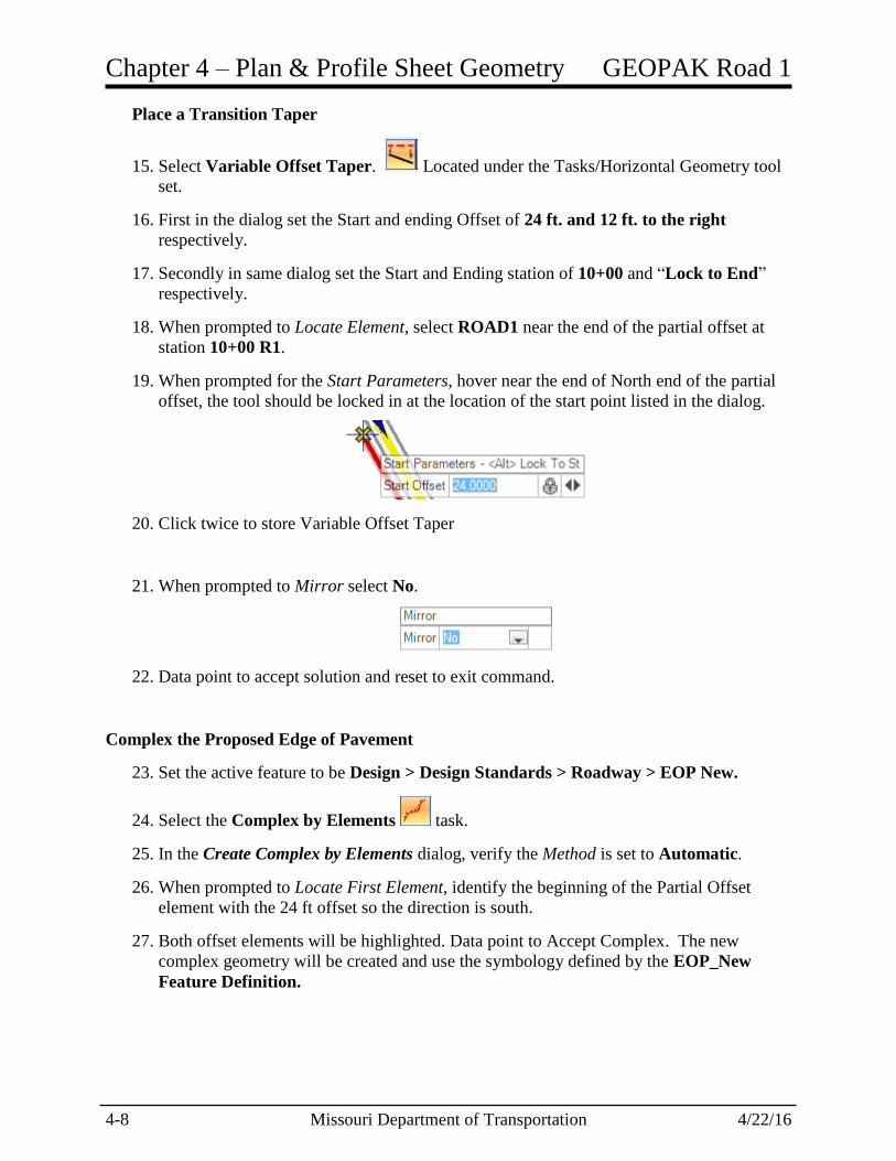
19. When prompted for the Start Parameters, hover near the end of North end of the partial
offset, the tool should be locked in at the location of the start point listed in the dialog.
20. Click twice to store Variable Offset Taper
21. When prompted to Mirror select No.
22. Data point to accept solution and reset to exit command.
Complex the Proposed Edge of Pavement
23. Set the active feature to be Design > Design Standards > Roadway > EOP New.
24. Select the Complex by Elements task.
25. In the Create Complex by Elements dialog, verify the Method is set to Automatic.
26. When prompted to Locate First Element, identify the beginning of the Partial Offset
element with the 24 ft offset so the direction is south.
27. Both offset elements will be highlighted. Data point to Accept Complex. The new
complex geometry will be created and use the symbology defined by the EOP_New
Feature Definition.
GEOPAK Road 1 Chapter 4 – Plan & Profile Sheet Geometry
4/22/16 Missouri Department of Transportation 4-9
Placing Right of Way Line
28. Create a new file named Land_Boundary_J2P0200.dgn based on the 2D seed file:
pw:\CADD_Standards\Seed Files\Design - English\i_project_2d_PowerGEOPAK.dgn
This new file will hold the geometry that can be used to display Right of Way information
in the Plan and XS View.
29. Reference the following files:
Civil_Geometry_J2P0200.dgn.
Terrain_J2P0200_Existing.dgn
Plan_J2P0200.dgn
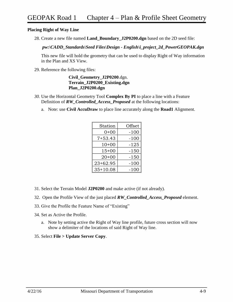
30. Use the Horizontal Geometry Tool Complex By PI to place a line with a Feature
Definition of RW_Controlled_Access_Proposed at the following locations:
a. Note: use Civil AccuDraw to place line accurately along the Road1 Alignment.
Station Offset
0+00 -100
7+53.43 -100
10+00 -125
15+00 -150
20+00 -150
23+62.95 -100
35+10.08 -100
31. Select the Terrain Model J2P0200 and make active (if not already).
32. Open the Profile View of the just placed RW_Controlled_Access_Proposed element.
33. Give the Profile the Feature Name of “Existing”
34. Set as Active the Profile.
a. Note by setting active the Right of Way line profile, future cross section will now
show a delimiter of the locations of said Right of Way line.
35. Select File > Update Server Copy.

Chapter 4 – Plan & Profile Sheet Geometry GEOPAK Road 1
4-10 Missouri Department of Transportation 4/22/16
4.5 Individual Exercise: Create Corridor Geometry for Route 63
If the edge of pavement and edge of shoulder of an existing road are required in the design file for
visualization or for future corridor work you can use the transition tools explored in the Road 1
exercise. Another option to create geometry is to use a template that matches what the existing
conditions are or proposed conditions. The Create Geometry by Template tool is used to apply
a template along existing geometry to create additional geometry.
Placing Right of Way Line Information.
1. Continue working in Land_Boundary_J2P0200.dgn.
2. Use the Horizontal Geometry Tool Complex By PI to place a line with a Feature
Definition of RW_Controlled_Access_Proposed at the following locations:
a. Note: use Civil AccuDraw to place line accurately along the Route63 Alignment.
Station Offset
9+50 150
25+67.20 150
27+67.20 150
28+00 200
30+00 200
35+00 200
40+00 200
43+00 200
43+79.95 150
45+79.95 150
70+79.95 150
3. Select the Terrain Model J2P0200 and make active (if not already).
4. Open the Profile View of the just placed RW_Controlled_Access_Proposed element.
5. Give the Profile the Feature Name of “Existing”
6. Set as Active the Profile.
a. Note by setting active the Right of Way line profile, future cross section will now
show a delimiter of the locations of said Right of Way line.
7. Select File > Update Server Copy.
GEOPAK Road 1 Chapter 4 – Plan & Profile Sheet Geometry
4/22/16 Missouri Department of Transportation 4-11
4.6 Group Exercise Exporting and Plotting Profiles - Road 1
1. Open the Civil_Geometry_J2P0200.dgn.
2. Right Click and hold in a blank area and select User Preferences.
a. Verify that the Working Directory is empty (clear out if needed).
3. In the User Preferences dialog select COGO Preferences.
a. Verify that the Job (GPK) Directory is empty (clear out if needed).
4. Select the “OK” button twice to close the two previous preference dialogs.
5. Open Classic COGO and open the 200 gpk.
6. Select COGO Navigator and view the Chain and Profiles listed in the gpk.
7. If the ROAD1 Chain, ROAD1EX or ROAD1PR profile is not listed, proceed to the
following steps. Otherwise skip to Step 11.
8. Open the ROAD1 Profile Model.
9. Select Task > General Geometry > Export to Native.
10. Any item listed in Step 10 that does not exist in the 200 gpk, select and export using
the Export to Native tool.
11. Create a new file named Profile_J2P0200.dgn based on the 2D seed file:
pw:\CADD_Standards\Seed Files\Design - English\i_project_2d_PowerGEOPAK.dgn
This new file will hold the profile sheet geometry.
12. Reference in the following 2D Project dgn files:
Civil_Geometry_J2P0200.dgn
Plan_J2P0200.dgn
Land_Boundary_J2P0200.dgn
13. Move to a blank area in the drawing away from the plan geometry.
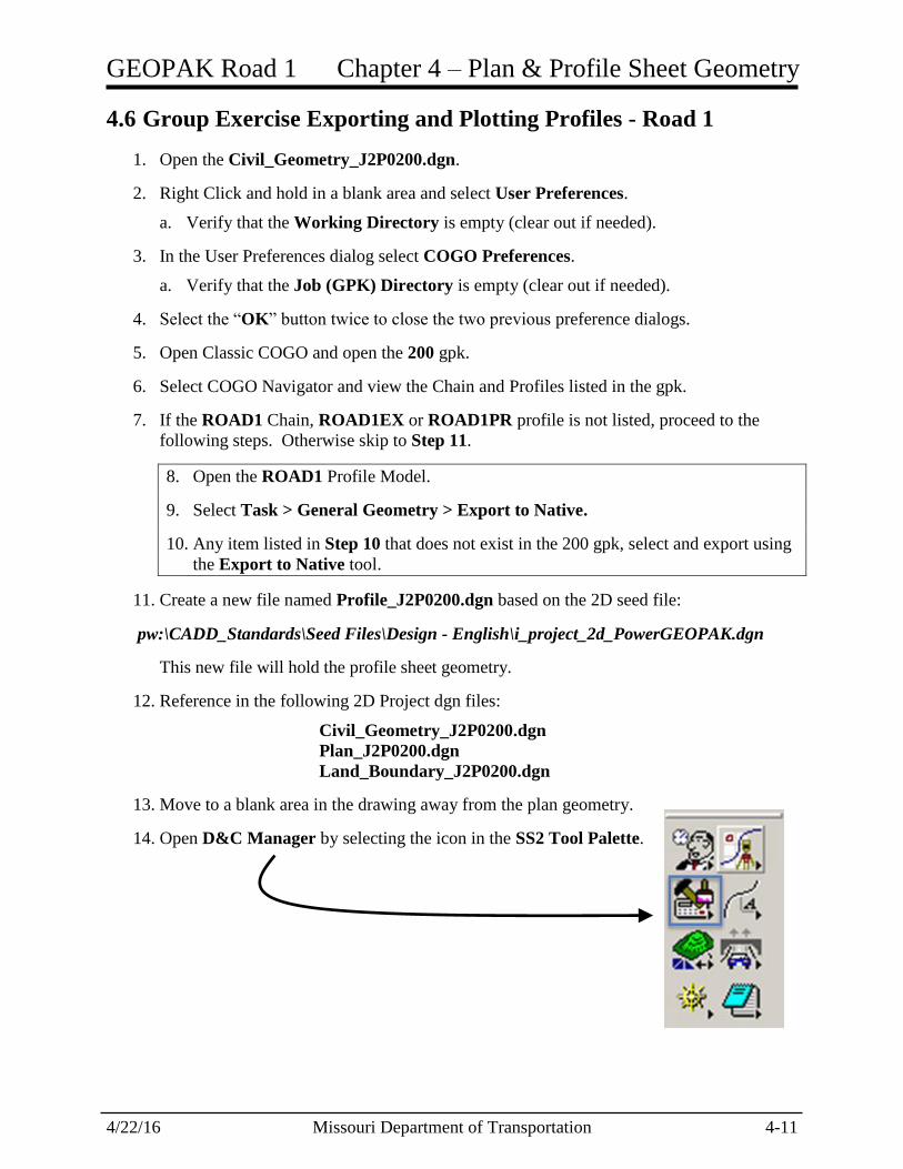
14. Open D&C Manager by selecting the icon in the SS2 Tool Palette.

Chapter 4 – Plan & Profile Sheet Geometry GEOPAK Road 1
4-12 Missouri Department of Transportation 4/22/16
15. Plot the ROAD 1 existing ground profile using the following Design and Computation
Manager item:
Drafting Standards\Profile\Existing Ground Profiles\1”=50’ Existing Ground Profile.
After selecting the item in D&C Manager, Click on Draw Plan & Profile in the
Operations Box.
Note: If prompted select the 200 gpk
16. Be sure all options are turned off, and the Labeling Scale is set to 50.
Choose the profile ROAD1EX.
GEOPAK Road 1 Chapter 4 – Plan & Profile Sheet Geometry
4/22/16 Missouri Department of Transportation 4-13
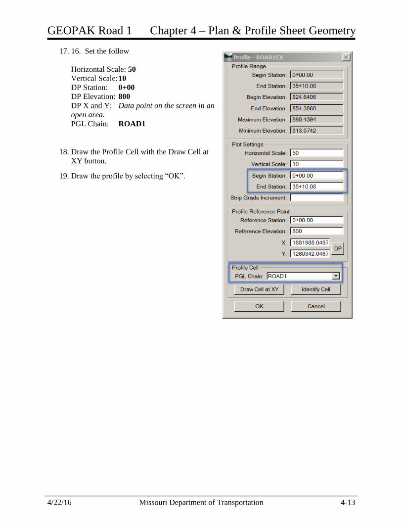
17. 16. Set the following parameters:
Horizontal Scale: 50
Vertical Scale: 10
DP Station: 0+00
DP Elevation: 800
DP X and Y: Data point on the screen in an
open area.
PGL Chain: ROAD1
18. Draw the Profile Cell with the Draw Cell at
XY button.
19. Draw the profile by selecting “OK”.

Chapter 4 – Plan & Profile Sheet Geometry GEOPAK Road 1
4-14 Missouri Department of Transportation 4/22/16
20. Plot the proposed profile using the following Design and Computation Manager item:
Drafting Standards\Profile\Proposed Ground Profiles\50 Scale Proposed Ground Profile
1”=50’ H & 1”=10’ V.
After selecting the item in D&C Manager, Click on Draw Plan & Profile in the
Operations Box.
Note: If prompted select the 200 gpk
21. Turn on the following options:
VPI Labels
Horizontal Axis Labels
Vertical Axis Labels
V.C. Parameters
Grade Labels
K Value
VPC/VPT Label
Stopping Sight Distance
Choose the profile ROAD1PR.
GEOPAK Road 1 Chapter 4 – Plan & Profile Sheet Geometry
4/22/16 Missouri Department of Transportation 4-15
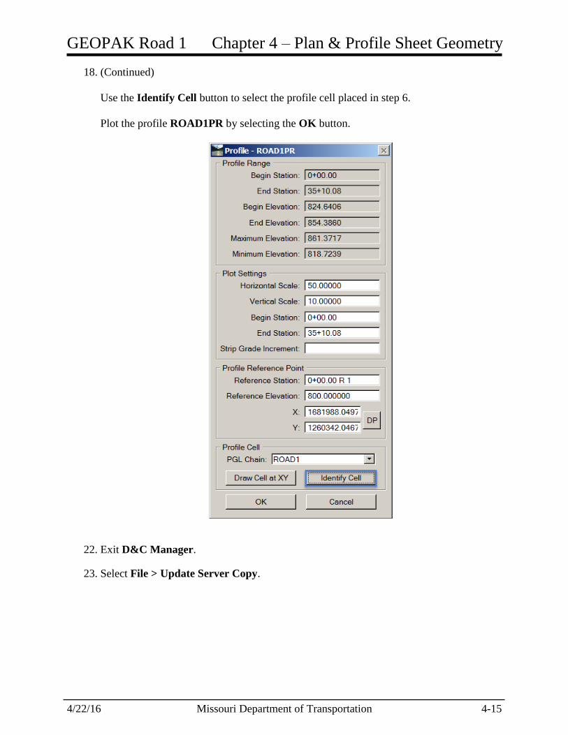
18. (Continued)
Use the Identify Cell button to select the profile cell placed in step 6.
Plot the profile ROAD1PR by selecting the OK button.
22. Exit D&C Manager.
23. Select File > Update Server Copy.

Chapter 4 – Plan & Profile Sheet Geometry GEOPAK Road 1
4-16 Missouri Department of Transportation 4/22/16
4.7 Individual Exercise Exporting and Plotting Profiles - Route 63
1. Open the Civil_Geometry_J2P0200.dgn.
2. Right Click and hold in a blank area and select User Preferences.
a. Verify that the Working Directory is empty (clear out if needed).
3. In the User Preferences dialog select COGO Preferences.
a. Verify that the Job (GPK) Directory is empty (clear out if needed).
4. Select the “OK” button twice to close the two previous preference dialogs.
5. Open Classic COGO and open the 200 gpk.
6. Select COGO Navigator and view the Chain and Profiles listed in the gpk.
7. If the ROUTE63 Chain, ROUTE63EX or ROUTE63PR profile is not listed, proceed to
the following steps. Otherwise skip to Step 11.
8. Open the ROUTE63 Profile Model.
9. Select Task > General Geometry > Export to Native.
10. Any item listed in Step 10 that does not exist in the 200 gpk, select and export using
the Export to Native tool.
11. Open the dgn file named Profile_J2P0200.dgn
12. Move to a blank area in the drawing away from the plan geometry.
13. Open D&C Manager by selecting the icon in the SS2 Tool Palette.
GEOPAK Road 1 Chapter 4 – Plan & Profile Sheet Geometry
4/22/16 Missouri Department of Transportation 4-17
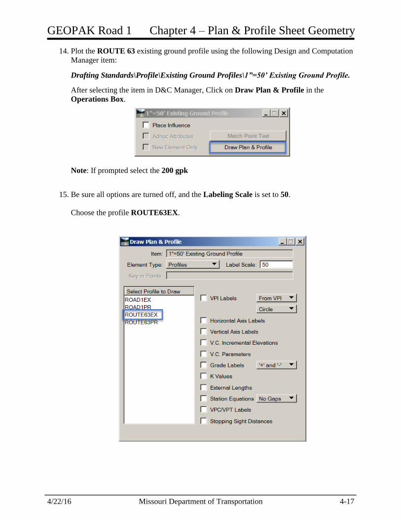
14. Plot the ROUTE 63 existing ground profile using the following Design and Computation
Manager item:
Drafting Standards\Profile\Existing Ground Profiles\1”=50’ Existing Ground Profile.
After selecting the item in D&C Manager, Click on Draw Plan & Profile in the
Operations Box.
Note: If prompted select the 200 gpk
15. Be sure all options are turned off, and the Labeling Scale is set to 50.
Choose the profile ROUTE63EX.
Chapter 4 – Plan & Profile Sheet Geometry GEOPAK Road 1
4-18 Missouri Department of Transportation 4/22/16
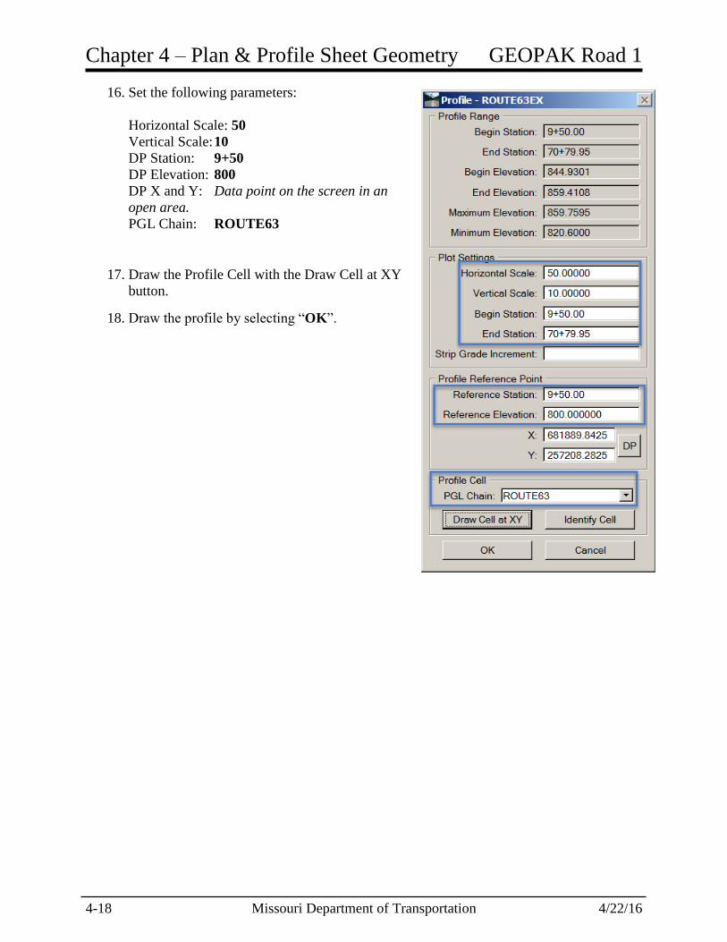
16. Set the following parameters:
Horizontal Scale: 50
Vertical Scale: 10
DP Station: 9+50
DP Elevation: 800
DP X and Y: Data point on the screen in an
open area.
PGL Chain: ROUTE63
17. Draw the Profile Cell with the Draw Cell at XY
button.
18. Draw the profile by selecting “OK”.

GEOPAK Road 1 Chapter 4 – Plan & Profile Sheet Geometry
4/22/16 Missouri Department of Transportation 4-19
19. Plot the proposed profile using the following Design and Computation Manager item:
Drafting Standards\Profile\Proposed Ground Profiles\50 Scale Proposed Ground Profile
1”=50’ H & 1”=10’ V.
After selecting the item in D&C Manager, Click on Draw Plan & Profile in the
Operations Box.
Note: If prompted select the 200 gpk
20. Turn on the following options:
VPI Labels
Horizontal Axis Labels
Vertical Axis Labels
V.C. Parameters
Grade Labels
K Value
VPC/VPT Label
Stopping Sight Distance
Choose the profile ROUTE63PR.

Chapter 4 – Plan & Profile Sheet Geometry GEOPAK Road 1
4-20 Missouri Department of Transportation 4/22/16
20. (Continued)
Use the Identify Cell button to select the profile cell placed in step 6.
Plot the profile ROUTE63PR by selecting the OK button.
24. Exit D&C Manager.
25. Select File > Update Server Copy.