chapter 4. plywood panel siding - uc agriculture ... 4. plywood panel siding 4.1 plywood panels...
TRANSCRIPT

chapter 4. PLYWOOD PANEL SIDING
4.1 PLYWOOD PANELS
4.1.1 Construction
Plywood panels are made up of an uneven number of layers or plys. Depending upon the type of panel, these plys can vary in thickness fiom a few hundredths of an inch for fine hardwood face veneers to 1/4 inch or so for the inner plys of some sheets of construction grade plywood. This range excludes lumber core plywood. Remember that these veneers are made by a sharp blade cutting a rotating log set in a lathe. After the log is cut, the veneers are flattened to make the plys. During the cutting and flattening process, the plys develop a continuous series of small cracks, called lathe checks, every 118 inch or so across the entire face of the sheet that was toward the inner side of the log. This "loose" side on face veneers is placed to the interior of the panel during layup.
4.1.2 Quality
The reputation of plywood siding has grown over time, through experience with the performance of panels manufactured from larger and more mature trees. The increasing use of different species and of smaller logs from generally younger forests, with changes in the manufacturing process, have changed the character of the product. The effect of these changes in raw material
and in manufacturing processes has seemed, in the author's opinion, to make plywood more vulnerable to exposure conditions. The authors also believe that the overall quality of construction plywood has decreased in recent years. It appears that core laps, core gaps, voids, glue skips, and use of decayed material have increased. These deficiencies are prone to cause failure.
For example, American Plywood Associa- tion standards for inner plys, unfortunately, are based solely on the structural characteristics of different wood species. This basis allows a wide range of inner plys that may or may not have a relation- ship to the face veneers. Some currently used inner plys are made of woods that decay rapidly when exposed to limited amounts of moisture. Obviously, if these panels are to be used in moist or wet con- ditions, the potential for decay is very high.
The designer and builder should make sure their specifications clearly control plywood quality, or else they should make sure the final installation appropriately uses products conforming to the commercial standards. Some mills produce a higher quality of product than required by the industry standards. When this higher quality is desired, it must be specifically called for.

chapter 4 - 2 WOOD: DETAILING FOR PERFORMANCE
4.1.3 Panel Size and Grade
The normal size of construction plywood panels is 4'-0" wide by various lengths, starting at 8'-0". Nine- and ten-foot-long siding panels are readily available, while panels longer than that are available only through special-order scarf joining. The plywood industry states that panels should be installed with 118 inch vertical gaps between sheets. The details in this manual do not show that recommended gap, because we believe it is unrealistic to frame a building with standard spacings that will yield a 4'-0-118" module. The author's concur with the industry that a 118" gap is desirable. While some manufacturers pro- duce siding panels at minus 118" to provide for this gap, panels are also made at minus 1/16" and at 4'0". We hope the industry will standardize at the 3'11-718" width so that this important expansion gap can be consistently provided. We believe that the best way to achieve this is through user demand.
4.1.4 Texture
Face veneers for plywood panels are available in a wide range of textures, species, and overlays. It is important to consider these surface properties in relation to the proposed use and exposure.
Textures, such as the grooves that cut deeply into the panels, effectively reduce the thickness of the plywood and decrease its resistance to bowing and cupping. These types of textures also expose the inner plys of the panel and the gluelines to the weather, which often results in less-than- satisfactory performance. For example, a
318-inch smooth-surface plywood panel might provide sufficient stiffness and resistance to bowing when applied to wood studs 16-inch on center; a 318-inch textured panel (not permitted in the APA 303 siding series - see Table 4-1) will probably not be sufficient because its effective thickness may be reduced to less than 114-inch by the grooves.
Table 4-1 303@ Siding Face Grades
Grade' Patches
wood Svnthetic
303-OC (Clear) Not Permitted Not Permitted
303-OL (Overlaid. Not Applicable for Overlays e.g. MDO Siding)
303-NR (Natural Rustic)
Not Permitted Not Permitted
303-SR Not Permitted Permitted as (Synthetic Rustic) Natural-Defect
Shape Only
303-*-W Limit * Not Permitted
Not Permitted Limit *
Limit * -Any Combination
'W-wood patch. S-synthetic patch, S/W-both wood and synthetic patches. The maximum number of patches allowed in 303 grades is 6, 18, or 30. One of these numbers will appear where the * is shown above.
4.2 WEATHERING PROPERTIES
Weathering is less obvious on saw-surfaced panels, and less surface deterio-ration will show than on smooth-surfaced plywood, but rough-sawn panels have a thinner surface veneer due to the manufacturing process.

WOOD: DETAILING FOR PERFORMANCE chapter 4 - 3
If left unprotected, the surface veneer can completely erode away in a few years, exposing gluelines and inner plys. Deterioration of the lathe checks on unprotected textured plywood can become severe and unsightly, which will ultimately lead to the total destruction of the surface ply, leaving gluelines or inner ply exposed to the weather. When textured, unpigmented surfaces are desired, large roof overhangs and frequent applications of a water repellent will probably be necessary to provide even minimal performance.
Plywood must be protected by a pigmented finish if it is to perform well. Surfaces left unprotected against weather and sunlight will soon show the lathe checks and other deterioration, which will be hard to hide even with a coat of paint. Because many paints do not provide much moisture protection, the designer may be misled in assuming levels of protection. A moisture-resistant paint or opaque stain offers the best level of normal protection available. A quality paint applied over medium-density overlay plywood panels probably offers the highest level of protec- tion and performance currently available.
Finishes are discussed in Chapter 15. However, the interactions between panel grade and finish choices need to be discussed here. Semitransparent stains are generally not satisfactory on overlaid panels or on panels with synthetic patches. Paints and solid-color stains may be used on any of the APA 303 sidings but sanded panels should be protected by paint.
Weathering is the composite effect of a number of degrading factors, and thus
different species exhibit a wide range of performance. The most important perform- ance variables are dimensional stability, leaching exposure, and resistance to ultraviolet light degradation. Mechanical strength, biological activity, thermal properties, and anatomical structure are also often significant. Lathe checks will appear sooner and will be more severe on sanded plywood, but they will develop to some degree on all softwood plywood exposed to the weather, regardless of species and finishing efforts. Medium-density overlay plywood is an outstanding exception to this rule. Redwood heartwood is a durable wood that has excellent resistance to weathering. It is, however, soft and subject to physical damage. Cedar heartwood has good decay resistance and excellent coloring, but unfortunately is soft and erodes rapidly because of degradation by light energy. When unprotected or finished only with clear water repellent, a resawn cedar plywood panel may completely lose its face veneer in five to ten years. Douglas-fir is tough and moderately decay resistant, but develops a severe checking pattern and weathers very poorly from a visual standpoint.
All woods are eroded by sunlight. In general, this erosion occurs at about 114- inch to 113-inch per century on vertical walls facing south. The greater the sun intensity, the faster the erosion. As an example of a high erosion rate, a redwood beam in Hawaii exposed to direct sun showed 5116-inch erosion in 35 years. In solid stock, where there is usually sufficient thickness to begin with, this is not normally a major problem. In vertical-grain solid stock, the soft and more fragile springwood

chapter 4 - 4 WOOD: DETAILING FOR PERFORMANCE
is protected by the ridges of the harder summerwood. In flat-grain solid stock and particularly plywood, with the very thin, resawn textured plys, this protection does not exist. The more vulnerable woods, such as cedar, are particularly risky. In general reference, the UV-resistance ranking of most woods is inversely proportional to their specific gravity. Specific gravity of common woods can be found in Table 6-1. Unfinished western redcedar, for some reason, erodes much more rapidly than would be expected from this general relationship; an erosion rate of between 518" and 314" per century is a reasonable expectation on a vertical wall facing south and subjected to leaching.
4.3 INSTALLATION GUIDELINES
4.3.1 Nailing
Improper panel nailing is one of the most pervasive errors currently found. This defi- ciency includes overdriving, shiners or air nails, inadequate nail length, excessive spacing, poor nailing patterns, and inadequate edge protection. When any of these deficiencies occurs singly or in combination, the potential for panel deformation exists. The more deformation, the greater the potential for water infiltration and panel degradation.
For quality performance of plywood panels, it is necessary to fasten them properly to the building framing. Nails must go into solid wood, they must penetrate the framing behind the plywood a minimum of 1-112- inch. At a minimum, this requires the use
of 8d nails on panels thicker than lD", 6d if 112" or less, and spaced no more than 6" at the edges and 12" in the field of the panel, provided lateral forces do not require heavier nailing. Only hot dip~ed galvanized or stainless steel should be used. Thermal withdrawal can be a serious problem with "smooth shanked" nails in some exposure conditions. This thermal action can be very rapid in aluminum nails, and while slower in steel and stainless steel, it does occur. Using nails with annular-ringed nail tips probably will reduce this thermal withdrawal, but until more is known about this phenomenon, the greater the penetration the better, with 1 - 112-inch the established minimum. Nail patterns must be uniform to avoid localized panel stressing, and the edge clearance condition must be adequate to avoid splitting and unsightly appearance. (See Chapter 14 for more discussion.)
Some comments about machine-driven fasteners are in order. These comments apply to all aspects of construction, with specific emphasis here on plywood diaphragms, sheathing, and siding panels. Labor and other cost savings of machine- driven fasteners are unarguable and should be encouraged. However, nailing gun manufacturers must face the issue of overdriven nails and the consequences for the building's structural integrity and other performance problems. It is essential that the nail head position must be pre- determined, with a positive stop. Positioning by friction results in extensive overdriving and loss of diaphragm strength. If a positive head position unit is not developed, we believe the acceptance of machine-driven fasteners by the building codes should be reconsidered.

WOOD: DETAILING FOR PERFORMANCE
4.3.2 Framing Shrinkage
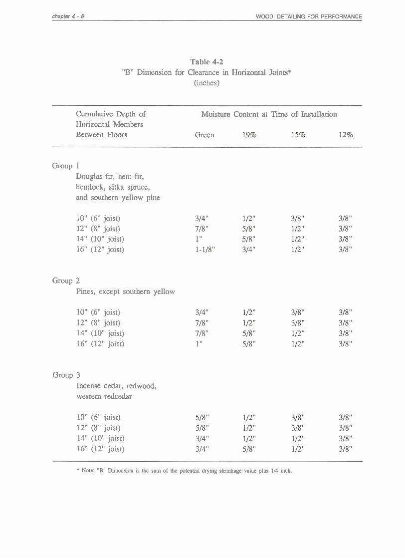
Longitudinal shrinkage in normal lumber, even green lumber, is so low that it can generally be ignored. However, some abnormal types of wood (juvenile and reaction wood) do have significant rates of longitudinal shrinkage, which may cause additional problems as the framing dries. Transverse shrinkage (across the grain) at plates, joists, and rafters can and often does cause major overall vertical changes. The severity of this change is directly related to the moisture content of the wood at the time of installation, the cumulative thickness of the horizontal members, and the eventual equilibrium of the basic building. The use of 19% KD moisture content framing will reduce shrinkage to about half that from using green lumber, but a significant amount will still take place. In deep-joist multiplate combinations, a 314-inch to 1-inch reduction of dimension because of shrinkage is not unlikely for green lumber. Table 4-2 gives some guid- ance on the average amount of shrinkage that should be anticipated for flat-grain Douglas-fir, although it usually will be less.
4.3.3 Vertical Installation
This is the most common application of plywood panels, which are usually nailed directly to the framing. Properly done, this system will provide good service. Most details in this chapter are related to vertical installation.
4.3.4 Horizontal Siding Installation
Horizontal application of plywood panel siding usually is not a good idea. This
method of application is sometimes used to accentuate the horizontal lines in a build- ing. However, the horizontal orientation makes the panels more vulnerable to degradation. Two factors contribute to this vulnerability:
As noted before, the plywood produc- tion process produces lathe checks that run parallel to the direction of the panel. When the panel is placed horizontally, these checks will collect water and facilitate decay, delamination, or both. The checks develop further with weather exposure, so even if the initial painting provides protection, it is unlikely that this protection will be maintained.
Most plywood siding has pattern grooves in the long direction of the panel. When placed horizontally, the grooves provide a ledge to hold water, which it can be absorbed into the panel body. More importantly, the grooves expose the end grain and lathe checks of the cross veneer, which absorb water readily. This end grain is very difficult to seal, and so even a groove with sloped edges is a problem. This moisture will not dry readily, thus promoting decay and delamination.
If a horizontal application is desired, plain panels without grooves should be used. The panel should also be sealed to protect the lathe checks. A medium-density overlay (MDO) surface is excellent. Horizontal joints should not be shiplapped, because shiplap joints have horizontal ledges. Horizontal joints should be flashed and supported by blocking behind the joint, as with vertically applied panels.
chanter 4 - 6 WOOD: DETAILING FOR PERFORMANCE
Table 4-2 "B" Dimension for Clearance in Horizontal Joints*
(inches)
Cumulative Depth of Horizontal Members Between Floors
Moisture Content at Time of Installation
12% Green
Group 1 Douglas-fir, hem-fir, hemlock, sitka spruce, and southern yellow pine
10" (6" joist) 12" (8" joist) 14" (10" joist) 16" (12" joist)
Group 2 Pines, except southern yellow
10" (6" joist) 12" (8" joist) 14" (10" joist) 16" (12" joist)
Group 3 Incense cedar, redwood, western redcedar
10" (6" joist) 12" (8" joist) 14" (10" joist) 16" (12" joist)
* Note: "B" Dimension is the sum of the potential drying shrinkage value plus 1/4 inch.

WOOD: DETAILING FOR PERFORMANCE chapter 4 - 7
4.3.5 Panel Thickness
Minimum panel thickness requirements specified by the building codes usually are based solely on structural considerations. These thickness requirements are not related to other performance criteria, such as cupping, bowing, or water infiltration. Panels that experience excessive deflection due to inadequate stiffness will probably allow the excess passage of water through their joints. Such water penetration exposes the plywood to decay and the membrane (often, unfortunately, not provided) to deterioration. Adequate stiffness is even more critical in the grooved textured panels (see Table 4-3). In addition, the plywood cantilever (the distance between the nail line and panel edge) necessary at inter- mediate floor systems and head and sill conditions is critical to avoid panel bowing from framing shrinkages. Table 4-4 gives recommended maximum cantilever dimen- sion "C" for different plywood thicknesses when the cantilever dimension is parallel to the face grain. The designer should to give balancing plywood cantilever and cross grain shrinkage of plates and joists.
4.3.6 Sealants
Good sealants are wonderful materials, but in the authors' opinion they should not be used as a primary membrane material in wood construction. Elastomeric sealants do not stick to wood very well without exten- sive surface preparation. Further, it is unusual in wood construction to find skilled sealant applicators within the normal labor force. More importantly, the bond between most sealants and wood deteriorates within
a few years, if the exposure is such that the sealant is actually performing a useful function. Sealants should be restricted to secondary water-shedding conditions or remedial work where they might receive the attention they need.
4.3.7 Finishes
See Chapter 15.
4.4 EDGE CONDITIONS
Joint detailing for installing panel siding is critical in terms of decay-resistant performance of panel siding systems. The design of the joints must accommodate proper nailing, drying shrinkage of framing, water-resistant joinery of the exterior panels, and protection of the felt membrane from sunlight. Figure 4-1 through Figure 4-17 illustrate some good and bad practices of joint detailing.
4.4.1 Vertical Joints
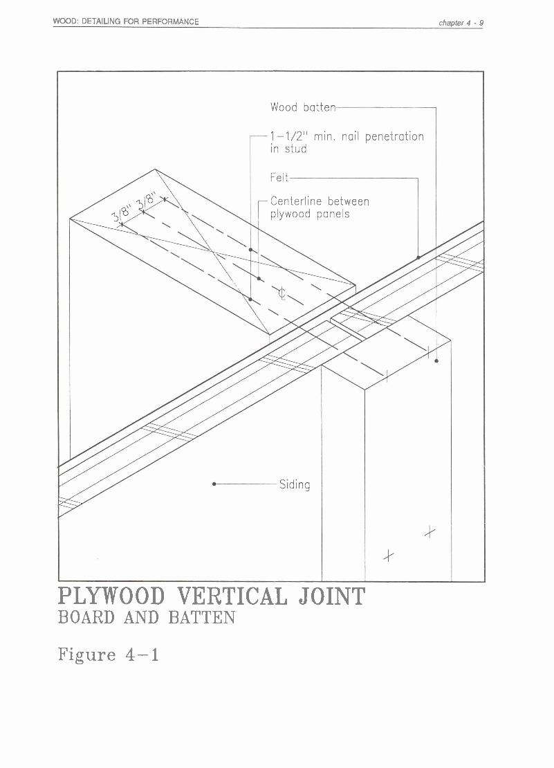
For vertical joints, both the board and batten joint (Figure 4-1) and the shiplap joint (Figure 4-2) are appropriate. Both have continuous overlapping of exterior material to protect the building membrane from exposure to sunlight, excessive water, and mechanical degradation.
Plywood manufacturers recommend a 118- inch space between panels. This expansion space has been omitted in the drawings for the reasons discussed earlier in this chapter in the section on panel size. Panel edge

chapter 4 - 8 WOOD: DETAILING FOR PERFORMANCE
Table 4-3. Recommended Plywood Thickness
Vertically Installed Plywood
Stud spacing
- -- - -
Panel Thickness
318" 1/2,, 518" & thicker Grooved Solid Grooved Solid Grooved Solid
Marginal No No
OK Marginal
No
OK OK OK OK Marginal OK OK OK
No Marginal Marginal OK
Recommended Plywood Thickness
Horizontally Installed Plywood
Panel Thickness
Stud spacing 318 " 1/2,, 518" solid + up
Textured Solid Textured Solid Textured Solid
The horizontally installed plywood part of this table should be used for overlay plywood. Smooth sanded plywood will develop excessive lathe checks and in moist conditions will . further deteriorate. Textured surface plywood should never be used in the horizontal direction.
Note: "Texture" here refers to all American Plywood Association 303 siding patterns.
WOOD: DETAILING FOR PERFORMANCE chapter 4 - 9
1 -1/2" min. nail penetration
Centerline between
PLYWOOD VERTICAL JOINT BOARD AND BATTEN
Figure 4-1

chapter 4 - 10 WOOD: DETAILING FOR PERFORMANCE
1 - 1 /2" min. nail penetration in stud
line between plywood
k
PLYWOOD VERTICAL JOINT
Siding
SHIPLAP
Figure 4-2

WOOD: DETAILING FOR PERFORMANCE chapter 4 - I I
Bonding of sealant to wood is usually very poor and often fails quickly. Subsequently, water can penetrate i f no felt is used, promoting decay in stud cavity.
SEALANT OVER MEMBRANE
A sealant joint over felt is not acceptable. As sealant fails quickly, water can penetrate and be trapped between the sealant and felt, causing the plywood panel to decay, and reducing the life of the
NO FELT MEMBRANE
It is necessary to provide felt behind shiplap and board and batten joints as these joints cannot be made completely water
PLYWOOD VERTICAL JOINT POOR PRACTICES
Figure 4-3

chapter 4 - 12 WOOD: DETAILING FOR PERFORMANCE
Table 4-4 "C" Dimension:
Siding Free Cantilever Distance (for vertical siding only)
Siding Thickness "C" Dimension
3/8" 3"
lf2" 5"
5/8" 12"
nails should be at least 318-inch from the edges, especially for panels in shear walls, where the panels exert large forces against the nails. The 318-inch space requirement keeps the panel edges from tearing against the nails. The size of nail should be ade- quate to penetrate the framing at least 1- 112-inch. Therefore, a minimum of 6d nails should be used for 112-inch thick and thin- ner panels. A minimum of 8d nails should be used for panels greater than 112-inch thick, with still larger sizes when gypsum board or insulating materials are between siding and framing. The vertical joints should always be supported by studs behind the joints. The studs must be placed precis- ely to accept nails from both panel edges. Because nail-to-edge distance of 318-inch is required, an error of 318", whether due to stud placement, warped studs, or misnailing, will result in nails missing the studs.
4.4.2 Horizontal Joints
For horizontal joints, the most economical and reliable method is the flashing joint (see Figure 4-4). The space between upper and lower panels, the "B" dimension, should be sized to handle shrinkage, as noted in Table 4-1, and covered by strips
of "Z" flashing. This space accommodates the shrinkage of floor joists as well as top and bottom plates of stud walls. Further- more, nailing of plywood panels should not restrict the shrinkage movement in the floor joists and plates. Therefore, horizontal joints should be located in between top and bottom plates at a floor level. Nailing of the plywood panels should be separated vertically as far as possible within this zone to minimize the nailing restraint of shrinkage. The recommended maximum free cantilever distance ("C" dimension) in Table 4-4 should be followed in locating nails. Figures 4-8 to 4-10 illustrate possible locations of the horizontal joint in this zone. If the panels are restrained in this area, large stresses will develop and cause plywood panels to bow and buckle, as illustrated by Figure 4-7. In one- or two- story buildings with low membrane expo- sure to wetting, it may be acceptable to place the membrane continuously behind the flashing. This detail can be an economical alternative.
To provide for shrinkage spacing, the recommended gap allows the bottom edge of the panel to be at least 114-inch away from the flashing ledge. This prevents wetting of the upper panel by capillary action from the collected water. The flash- ing also keeps water from penetrating the inner plys via the top edges of the lower panels. If the top edge of the lower panel is unprotected, water that collects on this ledge will seep into the center and back of the lower panel, where it is slow to dry out and will thus promote deterioration.
To be effective in wind-driven rain conditions, the " Z flashing should have

WOOD: DETAILING FOR PERFORMANCE
sufficient flange width (see Figure 4-4). As an alternative to flashing, staggered lapping of plywood panels and scarf glue joints are acceptable for horizontal joints (see Figure 4-4 and 4-12).
4.4.3 Panel Attachment (Figure 4-5)
When plywood panels must span floor joists, nails should not be placed at the panel edges at the horizontal joint as is normally recommended, but nailed near the top and bottom of the floor joists or plates, leaving the top and bottom edges unre- strained. The distances from the edge of the panels to the nailing line should not exceed the "C" dimension of Table 4-3. The panel should also be sufficiently thick to keep the free ends of plywood panels from bowing and deflecting outward.
4.4.4 Poor Practice - No Expansion Gap (Figure 4-6)
The drying shrinkage of wood is restrained. As the floor joist and plates shrink, the vertical load carried by the studs is transferred to the plywood panels. The induced stress can cause panels to bow outward. This detail can be used only if the lumber is kiln dried to 12% so that no further drying shrinkage will occur after construction. Even then this design is poor practice, because moisture will be absorbed through the lower edge of the upper panel.
4.4.5 FI-oor-Level Joints (Figure 4-8 to 4-10)
At floor levels, nailing of plywood panels should restrain wood shrinkage as little as possible. Because most shrinkage occurs at the floor joists and plates, the bottom nailing line of the top panel should be
located near the top of the floor joist. The top nailing line of the bottom panel should be located in the top plate of the stud wall or near the lower edge in the joist.
4.4.6 Alternative Floor-Level Joints (Figures 4-11 and 4-12)
These details illustrate alternative floor-level joint designs. Lapping plywood panels is an excellent way to provide a decay-resistant horizontal joint. This detail will require more labor to execute, the joint does not rely on flashing. This method can supply as much overlap distance as the exposure condition requires without using wide strips of flashing, which may be aesthetically undesirable. Both details illustrate nailing patterns that do not restrain the shrinkage movement in the floor joist.
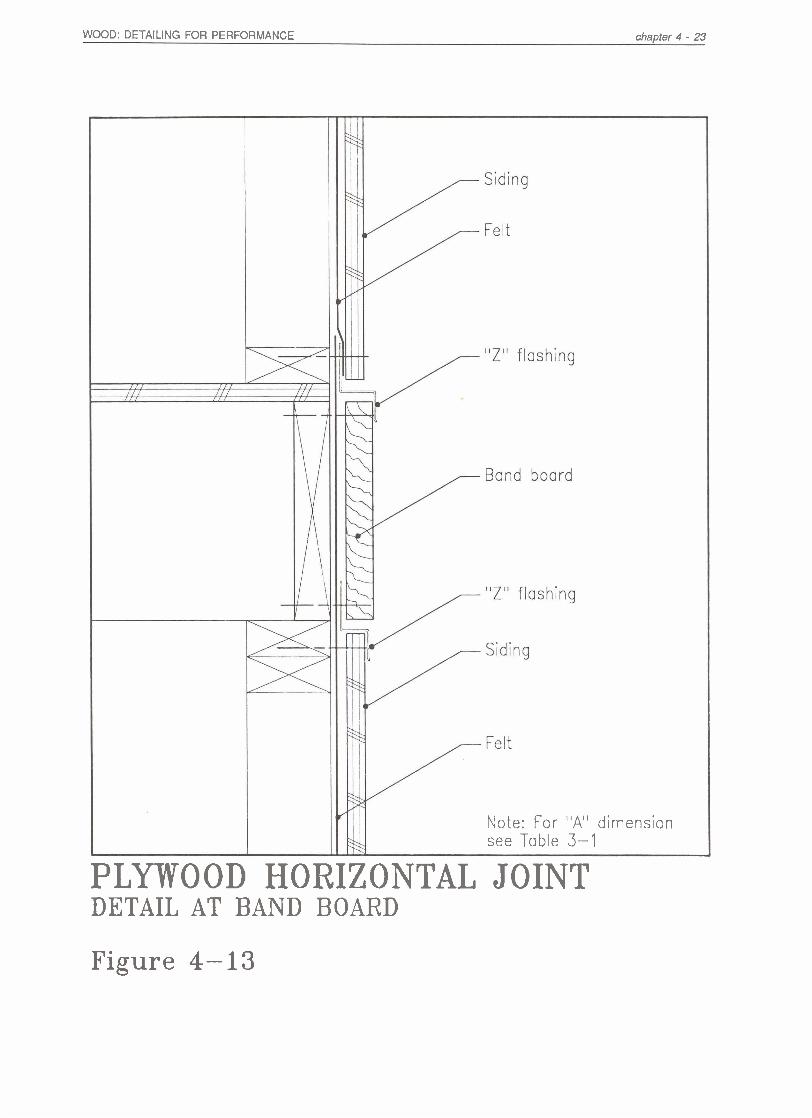
4.4.7 Banded Floor-Level Joints (Figures 4-13 and 4-14)
These details illustrate how a band board can be used with the floor-level joint. Band boards, also called beltline trim or a belt course, may be aesthetically desirable to emphasize horizontal lines in a building. The addition of the band board complicates the horizontal joint detail, because band boards must be protected by flashing unless they are treated with a preservative. If pre- servative treatment is used, both the ply- wood and the band board should be treated because water will be trapped between the two and decay may result, even at the second- or third-story level. In these details, two shrinkage relief joints are needed be- cause the band board must be attached to the floor joist. If only one relief joint is provided, the nails used to attach the band board will restrain shrinkage movement.

chapter 4 - 14 WOOD: DETAILING FOR PERFORMANCE
Felt
Siding
*
"Z" flashing a "A" min.
Wood frame backing
1 - 1/2" min. nail penetration in framing "B" min.
3/8" min.
"A" min.
Note: For "A" and "B" dimensions see Tables 3-1 and 4-1 Felt
PLYWOOD HORIZONTAL JOINT BUTT AND FLASHING JOINTS
Figure 4-4

WOOD: DETAILING FOR PERFORMANCE
Bottom nailing line
Note: For "A" and "C" dimensions see Tables 3-1 and 4-3
PLYWOOD HORIZONTAL JOINT DETAIL AT FOUNDATION
Figure 4-5
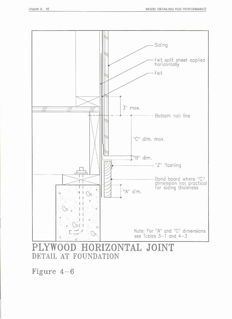
chapter 4 - 16 WOOD: DETAILING FOR PERFORMANCE
Bottom nail line
"C" dim. max.
Band board where "C" dimens- on not practical for s id~ng th~ckness
Note: For "A" and "C" dimensions see Tables 3-1 and 4-3
PLYWOOD HORIZONTAL JOINT DETAIL AT FOUNDATION
Figure 4-6

WOOD: DETAILING FOR PERFORMANCE
-Shrinkage restrained by nail
No expansion gap between plywood & "Z" f l ash~ng
PLYWOOD HORIZONTAL JOINT POOR PRACTICE
Figure 4-7

chapter 4 - 18 WOOD: DETAILING FOR PERFORMANCE
PLYWOOD HORIZONTAL JOINT DETAIL AT FLOOR LEVELS
Figure 4-8

WOOD: DETAILING FOR PERFORMANCE chapter 4 - 19
PLYWOOD HORIZONTAL JOINT DETAIL AT FLOOR LEVELS
Figure 4-9

chapter 4 - 20 WOOD: DETAILING FOR PERFORMANCE
PLYWOOD HORIZONTAL JOINT DETAIL A T FLOOR LEVELS
Figure 4-10

WOOD: DETAILING FOR PERFORMANCE chapter 4 - 21
PLYWOOD HORIZONTAL J O I N T DETAIL AT FLOOR LEVELS
Figure 4-11

chapter 4 - 22 WOOD: DETAILING FOR PERFORMANCE
0
Note: For "A" and "C" dimensions see Table 3-1
PLYWOOD HORIZONTAL JOINT DETAIL AT FLOOR LEVELS
Figure 4-12
WOOD: DETAILING FOR PERFORMANCE chapter 4 - 23
Note: For "A" dimension see Table 3-1
PLYWOOD HORIZONTAL JOINT DETAIL AT BAND BOARD
Figure 4-13

chapter 4 - 24 WOOD: DETAILING FOR PERFORMANCE
PLYWOOD HORIZONTAL JOINT DETAIL AT FLOOR LEVELS
Figure 4-14

WOOD: DETAILING FOR PERFORMANCE chapter 4 - 25
4.4.8 Floor-Level Joint (Figures 4-15 and 4-16)
Alternatives to providing two relief joints for a band board are to provide proper preservative treatment or to space the board away from the building surface. Neither of these methods requires that the band board be flashed. A single relief joint at the center is thus sufficient.
If a preservative treatment is used, both plywood and band board should be treated, because water will collect in the small gap between the band board and the plywood. Because of this, the flashing behind the plywood should also extend 2-inches above the band board in case this space overfills with water. The top of the band board (Figure 4-14) should also be sloped to minimize water collection at this ledge. An effective alternative to wood treatment is to provide a separation between the band board and the building surface (Figure 4- 15). When this approach is used, the separation space must be at least one-quarter the depth of the band board. This distance should be adequate to prevent clogging from debris. The spacers should not be continuous, to allow debris to fall through.
4.4.9 Poor Practice - Decay Hazard (Figure 4-17)
Water will collect between the band board and the plywood which will promote decay in this area. If the amount of collected water is significant and if no membrane is used, or if decay progresses, water will penetrate into the stud cavity, causing further damage.
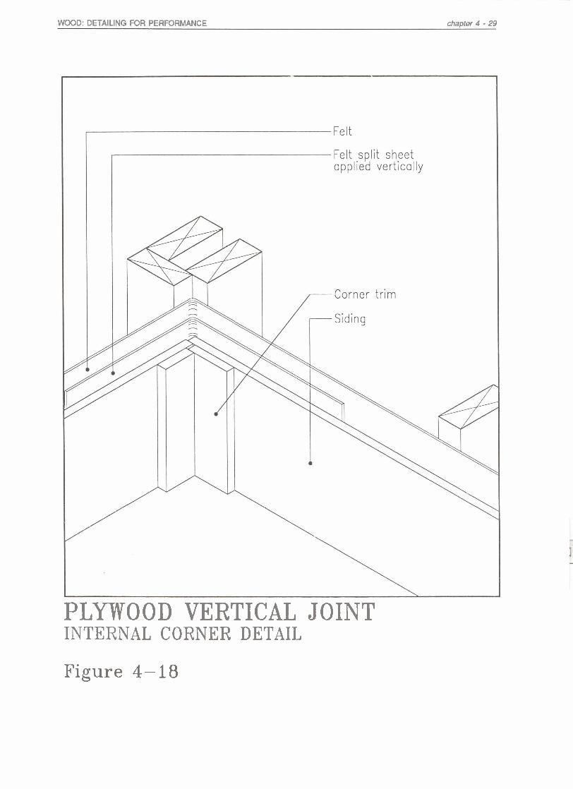
4.4.10 Corner Joints (Figures 4-18 and 4-19)
Battens, or comer boards, should be installed at exterior corners to protect the building membrane from sunlight degrada- tion at the panel joint. Comers are subject- ed to greater construction abuse, an addi- tional splitsheet of felt should be provided. The corner detail should include a 118" space at panel edge to accommodate possi- ble movement of plywood sheets as a result of framing shrinkage. Corner boards should also be supported by additional studs at the corner where needed, and they should be at least 3/4-inch thick and at most 4" wide to minimize cupping. All nails should pene- trate studs at least 1-112".
4.4.11 Joint Sealant
The sealant-to-wood bond is vulnerable. Although the initial condition may appear satisfactory, it can fail rapidly in adhesion when exposed to weathering. Failure may lead to water penetration, which promotes decay in the wall cavity. Surface applica- tions of sealant are not effective; butt joints are also vulnerable and cannot be relied upon. A sealant joint over felt membrane is also not acceptable. The sealant cannot be expected to exclude moisture for the life of the structure, but will interrupt the flow of penetrating water as the water flows down- ward between membrane and siding, caus- ing the plywood panel to decay and reducing the life of the membrane.
4.4.12 No Membrane It is necessary to provide felt membrane behind shiplap and board and batten joints. These joints cannot be made watertight.

chapter 4 - 26 WOOD: DETAILING FOR PERFORMANCE
Note: For "A" and "C"
PLYWOOD HORIZONTAL JOINT DETAIL AT FLOOR LEVELS
Figure 4-15

WOOD: DETAILING FOR PERFORMANCE chapter 4 - 27
Non-continuous spacers
PLYWOOD HORIZONTAL J O I N T DETAIL AT FLOOR LEVELS
Figure 4-16

chapter 4 - 28 WOOD: DETAILING FOR PERFORMANCE
Untreated wood
Untreated band board
No membrane
PLYWOOD HORIZONTAL JOINT POOR PRACTICE
Figure 4-17
WOOD: DETAILING FOR PERFORMANCE chapter 4 - 29
PLYWOOD VERTICAL JOINT INTERNAL CORNER DETAIL
Figure 4-18

chapter 4 - 30 WOOD: DETAILING FOR PERFORMANCE
PLYWOOD VERTICAL JOINT EXTERNAL CORNER JOINT
Figure 4-19