chapter 4 qas system interfacing
TRANSCRIPT

Chrysler
Quality Alert System (QAS)
Users Manual
1 of 10
Chrysler QAS Revision: Rev.0
OFFICIAL: Chrysler UPDATED: June 2, 2009
Chapter 4 QAS System Interfacing
In This Chapter � Floor QAS PLC
� Direct Communication Module (DCM)
� Ethernet (ENET) Card
� QAS Workcell
� Plant Floor Communication System (PFCS)

Chrysler
Quality Alert System (QAS)
Users Manual
2 of 10
Chrysler QAS Revision: Rev.0
OFFICIAL: Chrysler UPDATED: June 2, 2009
Floor QAS PLC
Purpose The Floor QAS PLC is an Allen Bradley PLC-5, which communicates
with other components for the following reasons:
• To receive the vehicle bar code from the AVI/VMS driver
• To receive vehicle data (bar code) from the AVI/VMS WCC
• To receive the distance traveled by the conveyor encoders to
provide location information for the tracking image
• To send necessary information to the QAS WCC to track an image
along the conveyor and corresponding QAS stations
Floor QAS PLC Communication
Flow
AVI/VMS
Driver
QAS Tracking
Image
Application
Encoder
QAS WCC
AVI/VMS
SystemBar Code Label
Vehicle Data
Tracking Image
Distance
Traveled
Floor
QAS
PLC

Chrysler
Quality Alert System (QAS)
Users Manual
3 of 10
Chrysler QAS Revision: Rev.0
OFFICIAL: Chrysler UPDATED: June 2, 2009
Floor QAS PLC Panel

Chrysler
Quality Alert System (QAS)
Users Manual
4 of 10
Chrysler QAS Revision: Rev.0
OFFICIAL: Chrysler UPDATED: June 2, 2009
Direct Communication Module (DCM)
Purpose The DCM is a chassis-mounted, single-slot I/O module that allows
communication between the Floor QAS PLC and the AVI/VMS
Supervisor PLC.
The DCM passes data between the Floor QAS PLC and the AVI/VMS
driver. The Floor QAS PLC transmits data through the backplane of
the chassis to the DCM. The DCM transmits data via an Remote
Input/Output (RIO) connection to the AVI/VMS Supervisor PLC.
The DCM link number is an address that provides the AVI/VMS
Supervisor PLC with a source and return address for information
requested from the Floor QAS PLC.
Dual Inline Package (DIP) switches on the DCM set link numbers.
DCM Communication Flow
Floor QAS
PLC
AVI/VMS
Driver
Backplane
DCM AVI/VMS
Suprv PLC
DH+
RIO
DCM Communications
Flow

Chrysler
Quality Alert System (QAS)
Users Manual
5 of 10
Chrysler QAS Revision: Rev.0
OFFICIAL: Chrysler UPDATED: June 2, 2009
Direct Communication Module

Chrysler
Quality Alert System (QAS)
Users Manual
6 of 10
Chrysler QAS Revision: Rev.0
OFFICIAL: Chrysler UPDATED: June 2, 2009
Ethernet (ENET) Interface Module
Purpose The plant floor Ethernet connects the Floor QAS PLC to the QAS
WCC through the ENET Interface Module on the Floor QAS PLC.
This module is side-mounted to the Floor QAS PLC.
The Floor QAS PLC and the QAS WCC communicate over the plant
floor Ethernet.
The Floor QAS PLC requires a Transceiver Module to communicate
on the network.
Ethernet (ENET) Interface
Communication Flow
Floor QASPLC
ENET QAS WCC
Ethernet (ENET) Communications
Flow

Chrysler
Quality Alert System (QAS)
Users Manual
7 of 10
Chrysler QAS Revision: Rev.0
OFFICIAL: Chrysler UPDATED: June 2, 2009
ENET Interface Module
Chrysler
Quality Alert System (QAS)
Users Manual
8 of 10
Chrysler QAS Revision: Rev.0
OFFICIAL: Chrysler UPDATED: June 2, 2009
QAS Workcell
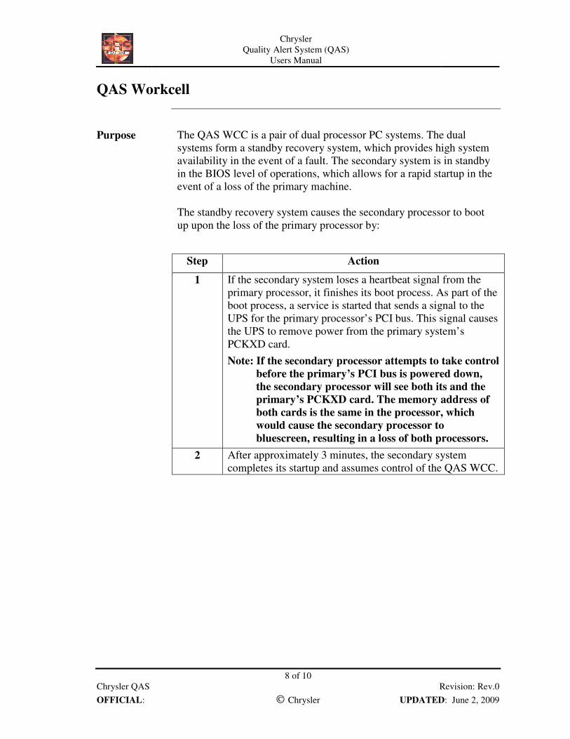
Purpose The QAS WCC is a pair of dual processor PC systems. The dual
systems form a standby recovery system, which provides high system
availability in the event of a fault. The secondary system is in standby
in the BIOS level of operations, which allows for a rapid startup in the
event of a loss of the primary machine.
The standby recovery system causes the secondary processor to boot
up upon the loss of the primary processor by:
Step Action
1 If the secondary system loses a heartbeat signal from the
primary processor, it finishes its boot process. As part of the
boot process, a service is started that sends a signal to the
UPS for the primary processor’s PCI bus. This signal causes
the UPS to remove power from the primary system’s
PCKXD card.
Note: If the secondary processor attempts to take control
before the primary’s PCI bus is powered down,
the secondary processor will see both its and the
primary’s PCKXD card. The memory address of
both cards is the same in the processor, which
would cause the secondary processor to
bluescreen, resulting in a loss of both processors.
2 After approximately 3 minutes, the secondary system
completes its startup and assumes control of the QAS WCC.

Chrysler
Quality Alert System (QAS)
Users Manual
9 of 10
Chrysler QAS Revision: Rev.0
OFFICIAL: Chrysler UPDATED: June 2, 2009
Software The QAS WCC contains the SoftLogix5 engine for operating QAS
control logic. SoftLogix5 runs on a PC computer that emulates an
Allen Bradley PLC-5/80. It runs as a service to the Windows NT
operating system, but will execute control logic in the same fashion as
a real PLC. QAS uses the SoftLogix5 engine instead of a real PLC for
these reasons:
• SoftLogix is able to connect to 36 I/O racks, as compared to 24 for
a real PLC.
• SoftLogix is able to make external auxiliary function (EAF) calls,
which means that SoftLogix is able to use additional programs
within its logic to determine outputs because it is processor-based.
SoftLogix5 also reads from a Realtime Database in the QAS WCC.
Currently, the Realtime Database is an Access97 database. The
SoftLogix5 engine communicates with the database in two ways:
• It uses ladder logic extensions (lgx) in the engine and
communicates via an ODBC/C++ DOA calls connection,
established in the workcell registry.
• It uses lgx in the engine and communicates via a Data Access
Object Software Development Kit (DAOSDK) connection. The
connection via ODBC is used for the workcell communications
with FIS, and the connection via DAOSDK is used for running the
database.
The QAS WCC also communicates with the Floor QAS PLC. The
QAS WCC receives the tracking image from the PLC and sequences
this image with the PFS terminals configured in the Realtime database.
In plants with ALS installed, the QAS WCC also sends the conveyor
run permissive signal to the Floor QAS PLC via a QAS sequence
panel.

Chrysler
Quality Alert System (QAS)
Users Manual
10 of 10
Chrysler QAS Revision: Rev.0
OFFICIAL: Chrysler UPDATED: June 2, 2009
QAS WCC Communications
Flow
QAS
WCCSoftLogix5
Engine
Realtime
Database
Floor QAS PLC
PFSPFCS
PFS
Terminal
The Realtime database in the QAS WCC communicates with a
Realtime database in the configuration database server. The Realtime
database in the configuration database server is copied to the QAS
WCC Realtime database using a Db copy utility. This action
minimizes the amount of time the Realtime database has to be down
for configuration changes.
Plant Floor Communication System (PFCS)
PFCS
PFCS provides a uniform store and forward function between plant
floor controllers, including the QAS WCC and PFS. Refer to PFCS
manuals for details.