chapter 4 structural variations
TRANSCRIPT
CHAPTER 4
STRUCTURAL VARIATIONS
Breakwaters, groins and j et ties are dif f creat. in purpose, s ize,
orientation and exposure to waves and other eaviroamental forces. They
all act, ia some degree, to reduce wave forces and bar littoral drift ia
the aearshore zone. Because they share this general function aad
milieu, they also share structural coafigurations. The two conventional
structural groups are the mound and wall types of shore stabilization
devices. A third category, low cost shore protection, reflects the
recent trend toward developing protection alternatives which are
economically feasible for private landowners. Subsets within each
classification are identified more commonly by their material
components, as rubble mouad and steel sheet pile wall. Common
structural methods are described in this chapter. General comments on,
desiga principles and illustrations of various devices provide a fuller
understanding.
The behavior and performance of coastal construction materials is
discussed by Hubbell and Kulhawy �979a! . Established materials, such
as steel, concrete and wood, and some of the newer choices. as gabions
aad synthetic fabrics, are covered in this work, so no attempt will be
made to repeat this information. Rock was aot considered in that study;
since it is the main material used for construction of breakwaters,
groins aad jetties, it will be dealt with herein. The durability and
availability of rock are described ia Chapter 6.
The purpose aad scale of the proposed project has a major impact on
selection of structural type. Larger-scale structures, as jetties and
113
ll4
breakwaters associated with major harbors, are founded ia deeper waters
and are subject to more complex and severe environmental loadings.
Coasequeatly, they must be massive structures and generally are of
coaventioaal design, such as rubble mounds or cellular sheet pile walls.
Smaller-scale, shallow water structures, including inshore breakwaters,
small lake jetties and groins, are suited to a wider range of materials
aad structural configurations. These may be adaptations of large-scale
methods, such as rubble mounds, or examples of innovative, less tested
designs, as the low' cost devices. Other factors to consider in material
selection are discussed ie Hubbell and Kulhawy �979a!.
The emphasis of this study is on the engineeriag of smaller-scale
shore stabilization structures. The design of rubble mounds is
presented ia Chapter 7. Wall structure desiga procedures are described
by Saczynski and Kulhawy ia preparation!. Some variatioas, notably
cellular sheet pile walls and concrete caissons, are typically used in
the larger installations. The general design consideratioas set forth
ia Chapter 5 apply to these, but presentation of precise technical
design procedures is outside the scope of this work because they require
detailed engineering studies and design.
4.1 MOUND STRUCTURES
Nearshore structures are often formed by dumping or placing
construction materials on the seabed in a mound shape. Mounds are
gravity structures which depend for their stability on their own weight
and massiveness rather than on foundation preparation. They effectively
atteauate wave eaergy through ruaup on their sloped faces and
dissipation within the voids of their rough surfaces.

Rubble mounds, described below, are the most familiar members of
this group. There is a large body of knowledge concerned solely with
the design. and behavior of rubble mound structures. Stepped face gabion
mounds are a relatively recent variation on the standard rubble mound.
Any material components which can interlock and maintain a stable mound
theoretically can be used for mound construction.
Rubble Mounds
By far, the most common structural configuration of breakwaters,
jetties and groins is the rubble mound, composed of layers of natural
quarried rock. The three general zones of a rubble mound profile are
illustrated in Figures 4.1 and 4.2. The core of small rock, referred to
as quarry-run ox quarry waste, generally comprises more than 50 percent
and up to 80 percent by volume of the rubble mound Fookes and Poole,
1981!. One or more intermediate layers, termed underlayers or filter
courses, overlay the core. These layers are graded according to filter
design principles to prevent erosion and loss of core material. The
primary covex or armor layer ultimately shields and stabilizes the mound
with large rock or concrete armor units. Although there may be
variations in practice, such as the elimination of underlayers or the
omission of core material in an all-armor rock mound, conventional
design of larger rubble mounds includes all three zones Quinn, 1972!.
The structural integrity of a x'ubble mound is highly dependent on
the ~eight and shape of armor rocks which envelope the mound. The armor
unit weight required varies directly with structure side slope, i.e.,
steeper slopes require heavier rock. The relationship of other
contributing parameters and the pxecise determination of design

Ch
4J4l4!
La!ClFl
Irk
z C XCl
4 DCJ
0 C 4CP
116
j IO
<k$

111
A
0 C CC
X CU C 0X ClC 04J
4J
8 4l WA ~
0
CV
1

118
specifications are detailed in Chapter 7. The availability of durable
rock must be evaluated as an adjunct to the design phase. investigative
and laboratory methods to perform this task are presented in Chapter 6.
When armor rock of the required size is unavailable, concrete shapes may
be specially formed to serve in their place; the characteristics of
concrete armor units are also described in Chapter 6.
Rubble mound jetties and breakwaters have been topped with
poured-in~lace concrete caps, as shown in Figure 4.1. Concrete use
ranges from simply filling in the voids between armor layer units, to
the much larger-scale casting of monolithic seawalls atop the mound
crest. Caps are designed to strengthen the crest, increase its height,
or provide a roadway along the crest for construction or maintenance
access CZRC, 1977!. These purposes are most applicable to the
construction of large-scale shore protection structures.
There are several advantages to using rubble mounds. They are
adaptable to any water depth and most foundation conditions. Settlement
of the mound under wave action usually results in readjustment of the
rock components to a more stable configuration, rather than in
structural failure. Structural damage is progressive, when it develops,
rather than sudden and potentially catastrophic. Damages are generally
easily repaired. As noted in Chapter 3, rubble absorbs rather than
reflects wave energy, a beneficial characteristic. On the negative
side, excessive transmission of wave energy may occur if the rubble
mound core is too low and porous. An additional disadvantage is the
large quantity of material required, an amount which increases
considerably for small increases in water depth. The initial project

119
cost is likely to be high if suitable constructioa materials are not
available locally CZRC, 1977!.
The ability to produce large quantities of rock economically, aad
the improvemeat of rubble mound design methods, have led to their
extensive use as shore protection elements. Zn view of their
importaace, the design of rubble mound structures warrants particular
attention. Chapter 7 is devoted to presentation of rubble mound design
technology.
Gabions
The adoption of polyviayl chloride PVC! coated wire, more than 20
years ago, for the manufacture of gabions enabled their use to be
extended to the coastal environment. The rock-filled wire baskets and
mattresses have been formed into mounds and incorporated into rubble
mounds to provide coastal defense works. Dimensions aad other features
of gabions are included in Hubbell and Kulhawy's �979a! survey of
coastal construction materials. The advantages of gabions, with respect
to this application, are: I! they are highly flexible and will adjust
to differential settlement, as caused by undermining from wave and
current scour, 2! they caa be filled aad placed underwater wi,th minimal
problems, 3! hydrostatic heads do aot develop behind the permeable
gabions, and 4! they are often aa economically attractive alternative.
Wave energy is absorbed within the interstices of the stones and, unlike
riprap, the rocks remain securely encased.
Gabions are well-suited to the construction of groins. The
individual building components are easily added or removed, so that the
groin configuration caa be altered in accordance with its effect on the

120
shoreline. The permeable gabions allow' peaetration of littoral drift
through the structure, a desirable feature which results in more uniform
beach accretion. The groin illustrated in Figure 4.3 is designed of
rock-filled wire mesh mattresses over a core of stone or sand fill.
Groias similar to the steyped mound design in Figure 4.4 may be employed
for shoreline stabilization. A wide ayron around the structure ensures
stabilitp. The ample flanks can settle and adjust, to underminMg by
erosion without threatening the struct iral integr'ty and usefulness.
Qn rubble mound breakvaters and jetties, gabions are used to cap
and protect the underlayers Figure 4.5!. Ia an innovative project,
gabioas vere used to form the breakwaters built at Tristan da Cunha, in
the South Atlantic, circa 1.964, when the islanders returned following a
volcanic eruytion. The two shore-connected breakwater arms comprise
rockfill founded on lava, overlain by a sloyed facing of gabions.
Though the small harbor protected is exposed to extremely violent wave
actioa, damages to the gabions have been limited Crowhurst, 1981!.
Along the coast of Bedok, Singapore, offshore breakwaters were
constructed entirely of gabions. These reached to just below the low
water mark, to encourage the deposition of sand on the beaches
immediately in their lee. A disadvantage of the chain link mesh used is
that breakage of single strands of wire can lead to unravelling and the
eventual collapse of the gabions. To date, these structures remain in
reasonable condition and have fulfilled the design objectives. In this
case of relatively light wave action, a vertical stepped face was used.
Where heavy wave action is anticipated, it is essential to use sloping
faces to allow additional energy dissipation ia runup Crowhurst, 1981!.

121
Figure 4.3 Revet Mattress Groin MaccaferriRevet Mattress Catalog, undated,p. 11!

122
e8

123
Figure 4.5 Gabion Reinforcement on Shoulder of Rubble HoundBreakwater Bekaert Gabions, 1977, p. 54!

124
4.2 WALL STRUCTURES
Straight walls dissipate energy largely by reflection rather than
by' absorption. They also differ from mounds in that they may fail or be
severely damaged by a single wave of more than design proportions
Dunham and Finn, 1974! . Sheet pile structures consist of lines of
piles interlocked to form a continuous wall. Piling materials include
steel, timber and, less commonly, concrete. Configurations range from
single walls, for small structures and low wave climates, to double and
cellular ~alls for more massive structures with more severe exposures.
Caissons, piles and cribs are other structural. variations within the
wall group.
Regardless of the configuration used, attention must be given to
foundation considerations See Chapter 5!. Piles must penetrate- to a
sufficient depth to attain structural stability against overturning.
Wall structures cause waves to generate scouring currents, which can
erode unconsolidated foundation materials and result in severe
undermining. Sheet piles have sometimes lost so much embedment as to
threaten their structural integrity. Cellular walls and caissons, which
rest on the bottom rather than penetrate to depth, are particularly
vulnerable; they have occasionally toppled seaward into their own toe
scoured trenches Dunham and Finn, 1974!. To protect against damaging
erosion, riprap must be placed along the toes of wall structures.
Sheet Pile Structures
Steel Sheet Piles. Single wall steel sheet pile structures are
used in low wave areas. In accordance with this constraint, they are
most successfully employed as groins, onshore breakwaters and other
125
shore protection elements subject to low structural. loads. These
systems may be designed as described by Saczynski and Kulhawy in
preparation!. The wave and soil forces to be resisted are evaluated to
determine the required depth of penetration of the sheet piles. This
value varies considerably with the nature of the foundation material
and, for this reason, a careful foundation study is warzanted. The
stability of the single wall depends on its strength as a cantilever
beam. %here the imposed bending forces are small, straight web piles
may be sufficient. To resist greater forces, deep web sections should
be used. The structural members of the groin illustrated in Figure 4.6
are deep web Z piles, restrained at the top by a steel channel.
eben the combined design wave and soil forces exceed the cantilever
strength of the sheet pile wall, bracing must be incorporated to prevent
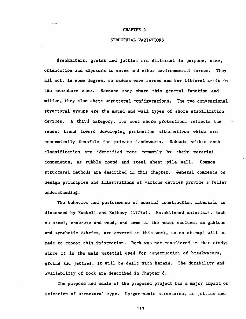
overturning. The single wall can be simply buttressed, as in Figure
4.7, by short lines of piles driven perpendicular to the main structure.
Bracing is similarly obtained by double wall construction. Two parallel
rows of sheet piling are connected and braced against each other with
tie rods and crosswalls, as shown in Figure 4.7. Each wall is stiffened
with inside wales. For added stability, the structure is filled with
granular material and capped with concrete, asphalt or heavy rubble
USCOE, 1963!.
The third steel sheet pile structural variation is the cellular
configuration. The groin illustrated in Figure 4.8 is of the diaphragm
type, a series of arcs connected to cross diaphragm walls. Granular
fill and capping provide added weight for structural stability. The
outward pressure from the fill results in circular or hoop tension in
the walls, contributing to resistance against tilting and overturning.

126 toneINetl
secviott a-i
Figure 4.6 Cantilever Steel Sheet Pile Groin CERC, 1977,p. 6-79}
127
Cl ~
00
ch
Q WCl QQ
Q4J4J Q3

128 p may be Mse4L,AN
~Pfl0 F1L
Figure 4.8 Diaphragm Type of Cellular Groin CERC, 1977, p. 6-80!
129
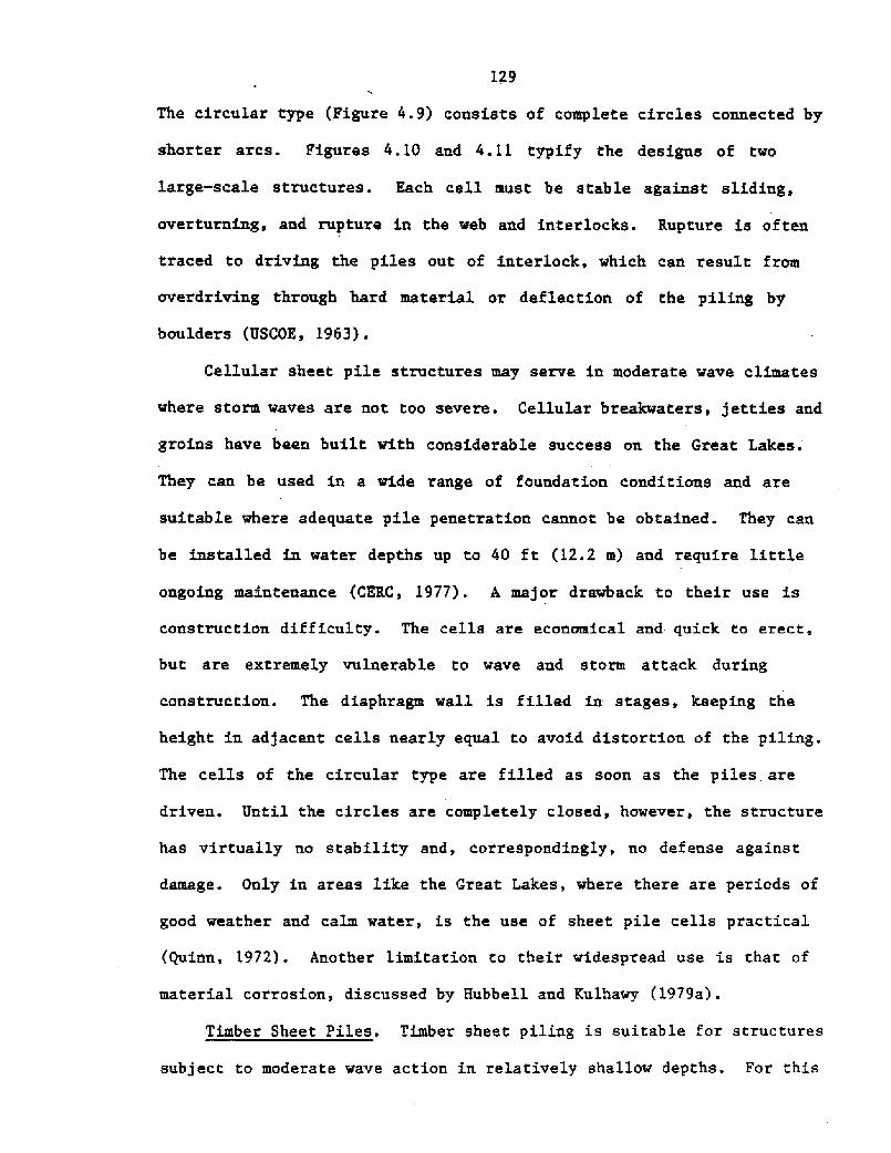
The circular type Figure 4.9! consists of complete circles coanected by
shorter arcs. Figures 4.10 aad 4.11 typify the designs of two
large-scale structures. Each cell must be stable against sliding,
overturning, and rupture in the web aad interlocks. Rupture is often
traced to driving the piles out of interlock, which can result from
overdriving through hard material or deflection of the piling by
boulders USCOE, 1963!.
Cellular sheet pile structures may serve in moderate wave climates
where storm waves are not too severe. Cellular breakwaters, jetties aad
groins have been built with considerable success on the Great Lakes.
They can be used in a wide range of fouadatioa conditions and aze
suitable where adequate pile penetration cannot be obtained. They can
be installed in water depths up to 40 ft �2.2 m! and require little
ongoing maintenance CERC, 1977!. A major drawback to their use is
construction difficulty. The cells are economical and quick to erect,
but' are extremely vulaerable to wave aad storm attack during
construction. The diaphragm wall is filled in stages, keeping the
height in adjacent cells neazly equal to avoid distortion of the piling.
The cells of the circular type are filled as soon as the piles are
driven. Until the circles are completely closed, however, the structure
has virtually ao stability aad, correspondingly, no defense against
damage. Only in areas like the Great Lakes, where there are periods of
good weather and calm water, is the use of sheet pile cells practical
Quinn, 1972!. Another limitatioa to their widespread use is that of
material corrosion, discussed by Hubbell aad Kulhawy l979a!.
Timber Sheet Piles. Timber sheet piling is suitable for structures
subject to moderate wave action in relatively shallow depths. For this
130
+ Asshole.-'ic co 7 vwjcac. Sscriov A.A7'eP.'ca ' P>: N
Figure 4.9 Circular Tyye of Cellular Breakwater {USCOE, 1963, pl. 15!

131
16 0
dimensions in meters!
Figure 4.10 Cellular Steel Sheet Pile Breakwater at Marsa elBrega, Libya Quinn, 1972, p. 250!
C.AXE HARSOR
Figure 4.11 Cross-Section through Cellular Sheet PileBreakwater at Calumet on Lake Nichigan Quinn, 1972, p. 2S2!
132
reason, timber groias are much more abundant than. timber breakwaters and
jetties. In any application, timber piling is not appropriate for use
on open, exposed shores. Ia view of the high cost, maintenance costs
and somewhat low life expectancy, timber should be considered only ~here
the purpose and local conditions warrant its special use USCOE, 1963!.
Figure 4.12 demonstrates the use of timber in a typical groin
configuration. Timber sheet piles are made of two 3 inch �6 mm! thick
timber boards staggered ia a shiplap joiat. This vertical wall is
framed. into a system of horizontal wales or stringers. Primary
structural support for the unit is derived from penetratioa of the rouad
timber piles. The wales and round piles also distribute the wave loads
and limit wall deflection and. the opening of joints between adjacent
sheet pi,les Ayers and Stokes, 1976!.
A low cost variation of this timber groin is shown in Figure 4.13a.
Piles are driven into the bottom in pairs, with planks saadwiched
between them. Because the plaaks caanot be embedded deeply when working
uaderwater, this method is limited to areas of wide tidal range where
construction can proceed during low tide. Rubber tires on timber piles
Figure 4.13b! comprise another low cost configuration, effective where
adequate pile penetration is obtainable. Horizontal timber crosspieces
keep the tires from floatiag off the tops of the piles in high water
Rogers, Golden and Halpern, 1981!.
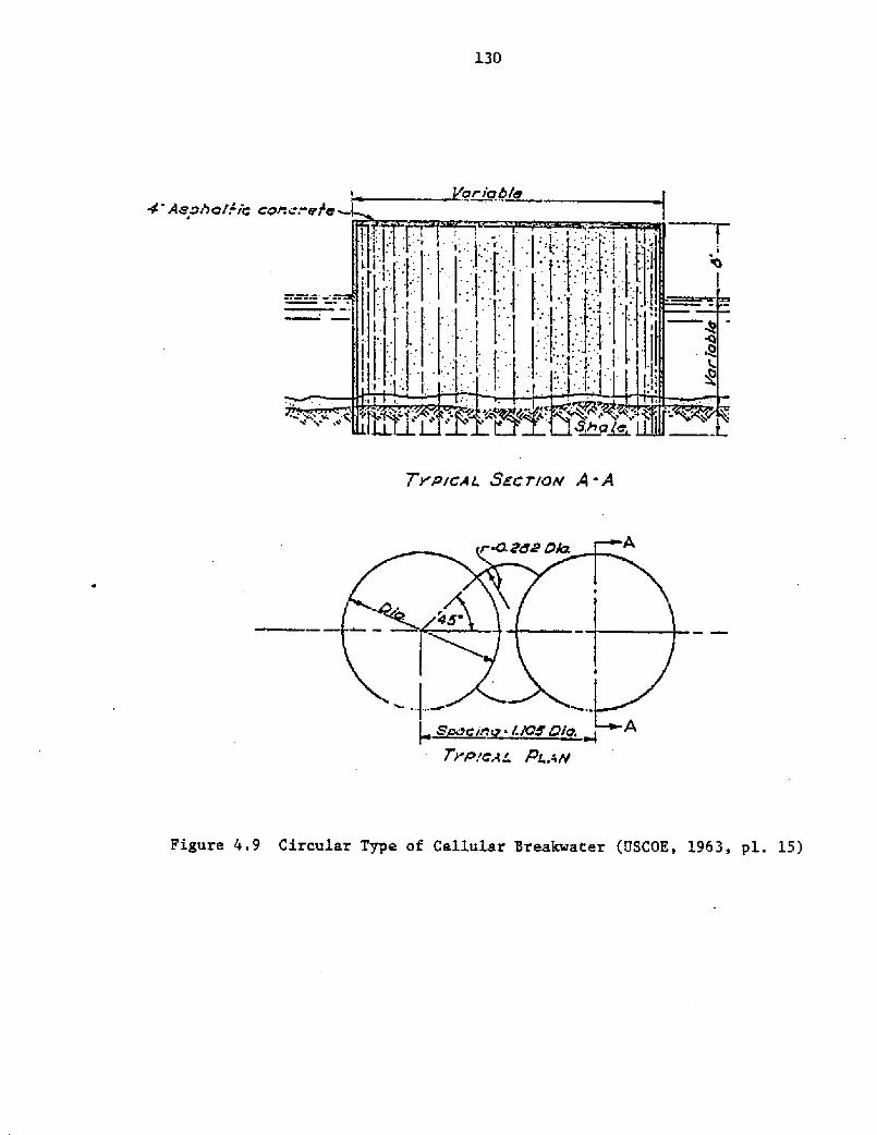
Concrete Piles. Concrete is one of the less common pile materials
employed in the constructioa of shore protection structures. A concrete
groin syst' em coastructed on the east coast of Niigata, Japan, is shown
in Figure 4.14. A bulkhead type breakwater Figure 4.1S! may be
suitable where soft bottom material extends to considerable depth and

133
ttef E:Oiaeeaiaaa aaa Cataila Io badatanaiaaa by aartiesler Oitacallaitiolta.
P%4FILEVIE% AA
"K "mWulaeral
StIIPLAP TONGUE ANO GROOVE WAKEF IELD
Figure 4.12 Typical. Timber Sheet Pile Groin CERC, 1977, p. 6-77!

134
a. Timber Groin O'N5 NRKl' 4 GapCifWdA
b. Timber Breakwater
Figure 4.13 Low Cast, Timber Shore Protection Rogers,Golden aad Halpern. 1981, pp. 17 and 20!
135
Figure 4.14 Concrete Block Groin, Niigata, Japan iorikawa. 1978, y. 331!
Figure 4.15 Concrete Sheet Pile Breakwater guinn, 1972,p. 256!

136
the wave height does not exceed 10 ft �.0 m!. Concrete sheet piling
and batter piles are driven through the soft stratum into the underlying
bearing material. These are capped above low water level with a
poured-in-place wall quinn, 1972!.
Concrete Caissons
Caissons used in coastal construction are reinforced concrete
shells with diaphragm walls which divide the box into several
compartments Figure 4.16!. The units are floated into position and
settled on a prepared foundation, either a rubble mound or piles. The
structure is filled with stone or sand and capped with concrete or armor
units for stability. k cast-in-place parapet wall may be added to
protect against overtopping. Heavy riprap placed along the base of the
caissons protects against scour and weaving on pile foundations, and
adds resistance to horizontal movement {CKRC, 1977!.
This type of construction has been used for breakwaters in the
Great lakes and for harbor protection in Europe. This scheme permits a
large amount of work to be done on land, an advantage where the sea is
rough and the working time of floating equipment is constrained Quinn,
1972!. Caissons can be used in depths of 10 to 35 ft � to 11 m!.
Their use is limited to breakwater and jetty construction; groins are
rarely subjected to forces that would justify usage of concrete
caissons.
Cribs
Cribs built of timber or precast concrete elements are utilized in
much the same manner as concrete caissons. Floored cribs are settled on
a prepared foundation and filled with stone. Timber, concrete or cap

137
k ~~h
Figure 4.16 Concrete Caisson Breakwater, Helsingborg Harbor,Sweden Quinn, 1972, p. 249!
Catt 4rrrf
Stare I'
TlmNr M
BREAKWATER AT HARBOR BEACH, I41CHIGAR
Figure 4.17 Timber Crib Breakwater USCOE, 1963, pl. 16!

138
stones provide, by their weight, additional stability. Rock-filled
timber cribs can withstand considerable racking and settlement without
rupture USCOK, 1963!. These have been used most extensively on the
Great Lakes, particularly in the past when timber was relatively cheap
in the area. A typical timber crib breakwater is illustrated in Figure
4.17.
4.3 LOW COST SHORE PROTECTION
The state-of-the-are of shore protection has been largely directed
at the protection of public and commercial property. However, 75
percent of the United States shoreline, excluding Alaska, is privately
owned Cousins and Lesnik, 1978!. Extensive and costly annual proyerty
loss is due, in part, to the private landowner's use of poorly conceived
and improyerly executed shore protection techniques. There is a great
need for information about low cost and usually smaller-scale protection
devices that can be successfully implemented by individual property
owners. Zn response to this need, Congress passed the Shoreline Erosion
ControL Demonstration Act of 1974. The legislation authorized the Corps
of Engineers to conduct a five year, eight million dollar program to
develop, demonstrate and evaluate low cost erosion control methods and
disseminate conclusions and guidelines to the public. The final project
reyort, presently in press, promises to provide important technical
assistance to private landowners. Sources of further proj ect
information are listed in Appendix A. An outline of the proj ect
f ramework f ollows.
Sixteen demonstration sites were chosen in the Delaware Bay,
Atlantic, Pacific, Gulf, Alaska and Great Lakes coastal regions. The
l39
erosion control projects installed were governed by the low cost
criterion, defined as $50 and $125 per front ft $164 and $400 per m! of
device. The former figure is for materials only, assuming the
landowners install the device, and the latter is for materials and
labor, assuming a contractor and heavy equipment would be necessary for
installation. The measures studied were intentionally of simple design
and intended to perform only on low energy coasts, with a maximum wave
height of 6 ft �.8 m!. Protection was designed for a ten year life
with minimum maintenance requirements. Naterials and techniques were
selected to be compatible with the geographical region of each project
Housley, 1978; Cousins and Lesnik, 1978!.
A sampling of the techniques proposed, in l974, to be studied is
given in Table 4.l. Some of these methods are previously tested
techniques on which better performance and cost data are needed; some
are innovations being tried for the first time. Nany are adaptations of
larger-scale shore protection technology while others seem particularly
suited to low energy, low cost, smal'-scale applications Housley,
1978!. Nounds, sheet pile walls and floating breakwaters are potential
low cost methods which have already been presented as structural
variations. Other breakwater and groin construction materials and
configurations cited in Table 4.l are discussed briefly in this section.
The final report of the Shoreline Erosion Advisory Panel Appendix A!
should be consulted for general conclusions and design guidelines
regarding these methods.

140
Table 4.1 Low Cost Shore Protection Techniques
Erosion Control StructureMaterial Bulkhead
Revetment and SeawallBreakwater Groin
Rubble
with Asphalt Mastic
J JSheet Piles
Gabions
Fabric Bags
Longard Tubes
Rubber Tires
Cribs
Z Wa13.
Concrete Blocks
Corrugated Pipes
Steel Fuel Drums
Additional tested methods include: coastal vegetation, beach fill,perched beaches.

141
Lon. ard Tubes
The Longard tube is manufactured by the Aldek Company of Denmark
and distributed in the United States by the Edward Gillen Company of
Milwaukee, Wisconsin. The Longard tube is essentially an enveloye of
material given structural capability by sand filling. The tube is a
polyvinyl-coated outer shell of woven material lined with polyvinyl,
sheeting. Sand pumped as a slurry into the tube provides the shell with
weight and strength. A tray of filter cloth at one end retains the fill
while allowing water to drain out.
Longard tubes have been used as groins in Michigan's Demonstration
Erosion Control Program, a study similar in purpose to the federal
program. The 42 and 69 inch �.1 to 1.7 m! diameter tubes were
installed singly and stacked, one on two, in a pyramid configuration.
To keey the costs of installation within the low cost range, the tube
grains were placed directly' on the lake bottom with no foundation mat,
filter layer or toe protection. Undermining and settlement of the
structures was, consequently, serious on sandy bottoms. Longard tubes
are susceptible to tearing and loss of sand, resulting from impact of
ice, debris and boats. vandalism, or improper sealing during
construction. Structure life and efficiency are, limited subsequent to
such damage.
Barring major damage, the tubes functioned reasonably well as
groins. Longard tubes do not have the longevity associated with more
massive, durable materials, but their low cost can offset this primary
disadvantage. Za the Michigan project, the cost of Longard tubes was as
low as $40 per ft $131 per m! front of shoreline protected. The ease
142
of construction, too, recommends the tubes as a competitive new concept
in shore protection Armstrong and Kureth, 1979; Brater, et. al., 19?7!.
Sand-filled Ba s
A number of field installations of the Michigan Demostration
Erosion Control Pzogram made use of large nylon sand-filled bags as
groins and revetments. Several of the structures were damaged. by
vandalism and impact by debris. An interim project evaluation concluded
that the sand-filled bags were failing at such a rate that considerable
cost would be required to restore and maintain their original condition
Brater, et. al. 1977!. Yearly replacement of bags on the groins was
projected as a necessary maintenance measure Armstrong, 1976!.
Sandbag groins, zevetments and breakwaters have been constructed
with varying degrees of success by private homeowners and communities.
To generate rational design data, CZRC initiated a project in 1968 to
investigate the stability and effectiveness of sand-filled nylon bag
breakwaters under the attack of shallow water waves. Results of
full-scale laboratory tests, using standazd size bags 5 ft �.5 m! vide
by 8 ft �.4 m! long, are reported by Ray �977!. Several breakwater
configurations similar to that shown in Figure 4.18 were tested in 12 ft
�.7 m! of ~ster. Only breakwaters with crests above or slightly belo~
the stillwater level effected vave attenuation greater than 30 percent.
The data indicate that an effective sandbag breakwater, producing
significant changes in wave height, will be susceptible to damaging
amounts of bag movement and must be designed and constructed carefully
to maintain a stable configuration. Some preLiminary design guidelines

143

144
are given by Ray �977! and additional information is expected in the
Shoreline Erosion Control Demonstration Program report.
Testing problems associated with the use of sandbags included
ultraviolet deterioration, closing filled bags and handling the bags,
especially when frozen. A single uncoated nylon bag exposed to direct
sunlight for 18 months tore open. Commercially marketed bags have since
been improved with various plastic coatings to reduce exposure damage.
Bags have been equipped with a self-sealing opening which allows them to
be hydraulically filled while lying flat. Also, the bags are now being
manufactured of heavier, more coarsely woven material with increased
strength. Trapped air and water can more readily escape through the
permeable envelope, enabling quicker consolidation and interlocking of
the sandbags Ray, 1911!.
Rock Mastic
A rock asphalt-mastic groin was constructed in 1973 under the
supervision of the University of Michigan's Coastal Zone Laboratory.
Although existing literature recommended that mastic not be poured
through more than 1 ft G.3 m! of water, the installation of this groin
demonstrated that mastic can be successfully poured through 7 ft �.1 m!
of water.
The rock mastic groin is 60 ft �8.3 m! long and has trapped large
amounts of sand, providing a protective beach Figure 4.19!. The
structure was installed at a cost of $45 per ft $146 per m! of
shoreline, and anticipated maintenance costs are quite low. The rock
mastic lacks the aesthetic qualities of other materials, but the
structure has proven stable and effective. The rock mastic groin has

145
a. Plan View
~ f A e' er V m rt ee' ne
b. Profile
Figure 4.19 Rock Mastic Grain, SanilacTownship, Michigan Brater,et. al., 1977, p. 38!

146
performed satisfactorily and is a good example of successful, innovative
low cost shore protection Brater, et. al., 1977!.
Precast Concrete Units
Permeable groins have been designed of precast concrete members and
piles. Considerations in the use of waterfront concrete are presented
by Hubbell. and Kulhawy �979a!. A new concept in low cost breakwater
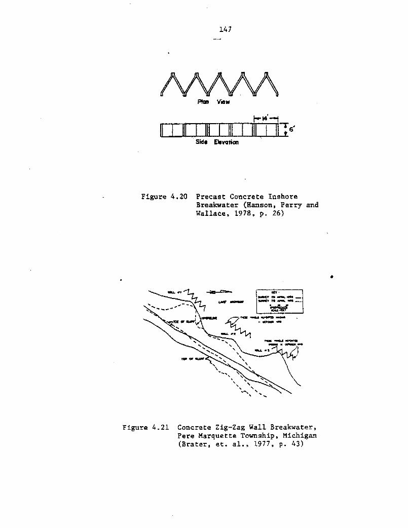
design was tested in Pere marquette Township on Lake M.chigan. The
breakwater consisted of precast, reinforced concrete panels bolted
together to form zig-zag walls Figure 4.20!. Three walls were placed
offshore, with 50 ft �5.2 m! spacings between structures. The
breakwater system initially functioned well in building up a beach and
preventing bluff recession Figure 4.21!. A ma]or storm, with 6 to 10
ft �.8 to 3.0 m! ~aves, then caused extensive damage to the breakwater
and bluff. ~ Presently, the structures are totally useless and bluff
recession has continued unchecked. The experimental use of precast
zig-zag walLs vas intended for onshore use only. Their performance in
this offshore application was unsatisfactory Srater, et. al., 1977!.
The Pere Marquette breakwater was constructed without a foundation
and toe protection so that it would fit the low cost classification. It
is certain that inclusion of these basic features would have improved
overall structural performance and averted such a failure. As
demonstrated by this case, design modifications and omissions made for
the sake of economy must Ee carefully weighed. Elimination of these
aspects may save first-cost dollars, but will often result in structure
undermining and settlement. A structure which eventually requires large
maintenance expenditures or is rendered inoperable is no bargain. A
147
6
Side Be vatic
Figure 4.20 Precast Concrete InshoreBreakwater Haasoa, Perry andWallace, 1978, p. 26!
Figure 4.21 Concrete Zig-Zag Wall Breakwater,Pere Marquette Township, Michigan Brater, et. al., 1977, p. 43!

148
little extra investment in properly engineered design at the outset
could save greatly on overall project costs.
Other Materials
Any material that has an acceptable lifespan, is non-polluting and
will remain stable under the imposing environmental forces has potential
for shore protection construction. Low cost surplus ships, barges and
drydocks are nontraditional building materials, yet can suitably perform
as offshore portions of breakwaters, groins and jetties. They are
simply towed into place and sunk. A major drawback to their use is the
difficulty and cost of their removal when they deteriorate to the point
of disuse.
Experiments with innovative no-cost materials proceed as well. One
substance that is the subject of intensive research in the United States
is stabilized blocks of waste material from coal fired power plants. 'Ln
areas dependent. on coal for electrical generation, the waste blocks
might be used to build reefs and submerged breakwaters Sanko and Smith,
in preparation!.
A rubble dike breakwater to protect small craft at the New York
World's Fair Marina was built entirely of no-cost fill. Truckers paid a
premium for the privilege of convenient disposal of heavy construction
debris and rubble. The only method of achieving a stable embankment was
to displace the 70 to 80 ft �1 to 24 m! of soft organic clayey silt
deposits, replacing their volume with the fill. An overload to a height
of 20 ft �.1 m! above MLW was intentionally maintained throughout the
fill process to assure displacement of the in-situ material. At. the
advancing tip of the breakwater, successive passive failures in the
149
clayey silt formed. mud waves around the mound as disylacement progressed
Figure 4.22a!. This heaving of bay bottom provided lateral support to
the body of the fill and acted as a consolidation load to strengthen the
remolded silt adjacent. to the fill. The construction rate of sinking
was approximately 1 ft per hour �.3 m per hour!. Zn the final
configuration Figure 4.22b! probings indicated that the mound sides
vere vertical and that rubble had penetrated as much as 70 ft �1 m!
into the soft organic silt. The breakwater has a length of 3000 ft 914
m! and a crest width of 40 to 50 ft �2 to 15 m! at 18 to 20 ft �.5 to
6.1 m! above MLW. The costs incurred in this unique project were for
engineering design and supervision of construction only. Similar
displacement embankments might be ayproyriate vhere the underlying
deposits are too soft to support fill loads and the resulting
displacements can be tolerated, and an ample supply of inexpensive fill
is available Torikoglu, 1966!.
4. 4 StmeV&Y
The general structural variations of breakwaters, jetties and
groins are similar. The exact purpose and scale of the project play a
major role in selecting from among the available configurations; harbor
breakwaters and jetties are typically massive structures of conventional
design while smaller jetties and groins are suited to a wider range of
materials and designs. The three structural groups addressed are
mounds, walls, and low cost shore protection methods. Construction
materials are discussed only briefly here; a more complete treatment of
the subject is included in Hubbell and Kulhawy �979a!.

150
a. Sequence of fill construction
b. Final configuration
Figure 4.22 NoWost Fill Breakwater, New York Torikog3.u, 1966, p. 59!

151
Hounds are broad-based structures which derive their stability
largely from their weight. They absorb and dissipate wave energy
through runup on their rough, sloped faces. The most advantageous
characteristic is their response to damage; they tend to settle and
readjust progzessively, usually without severe consequences. Rubble
mounds, comprising layers of quarried rock, are the most common
structural configuration of breakwaters, jetties and groins. They are
effective structures, because of the large laboratory and field data
bases associated with their design. The use of gabion mounds is less
widespread at present, but seems to be a viable alternative. Gabions
are particularly appropriate for groin construction, where the
transmission of wave energy through the permeable structuze is not
czitical.
Walls reflect wave energy. When attacked by waves higher than the
design wave, they can fail suddenly; their design specifications must
therefore be more demanding. Steel and timber sheet piles can be used
in low, moderate or higher wave climates, in single wall, double wall or
cellular configurations. Foundation considerations Chapter 5! are
quite important in assuring pile penetration to the design depth.
Concrete caissons can serve as larger-scale breakwaters and jetties. At
these and other wall structures, riprap must be placed along the base to
protect against foundation scour.
Low cost shore protection is a new and exciting trend in
small-scale protection alternatives. Low cost breakwaters and groins of
innovative design and unusual materials are among the experimental
structures being studied by the U.S. Corps of Engineers. Sand-filled
tubes and bags, rock-mastic mounds, gabions, and float'ing breakwaters
152
appear to be successfuL and comyetitive protection methods.
State-of-the-art information on low cost shore yrotection deveLopments
can be obtained as described in Appendix A.