chapter 4 the building blocks: binary numbers, boolean logic, and gates
TRANSCRIPT
Chapter 4
The Building Blocks: Binary Numbers, Boolean Logic, and
Gates
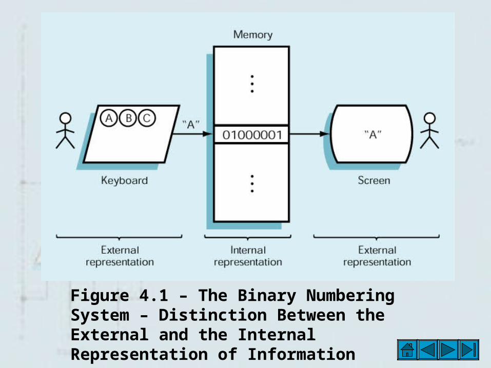
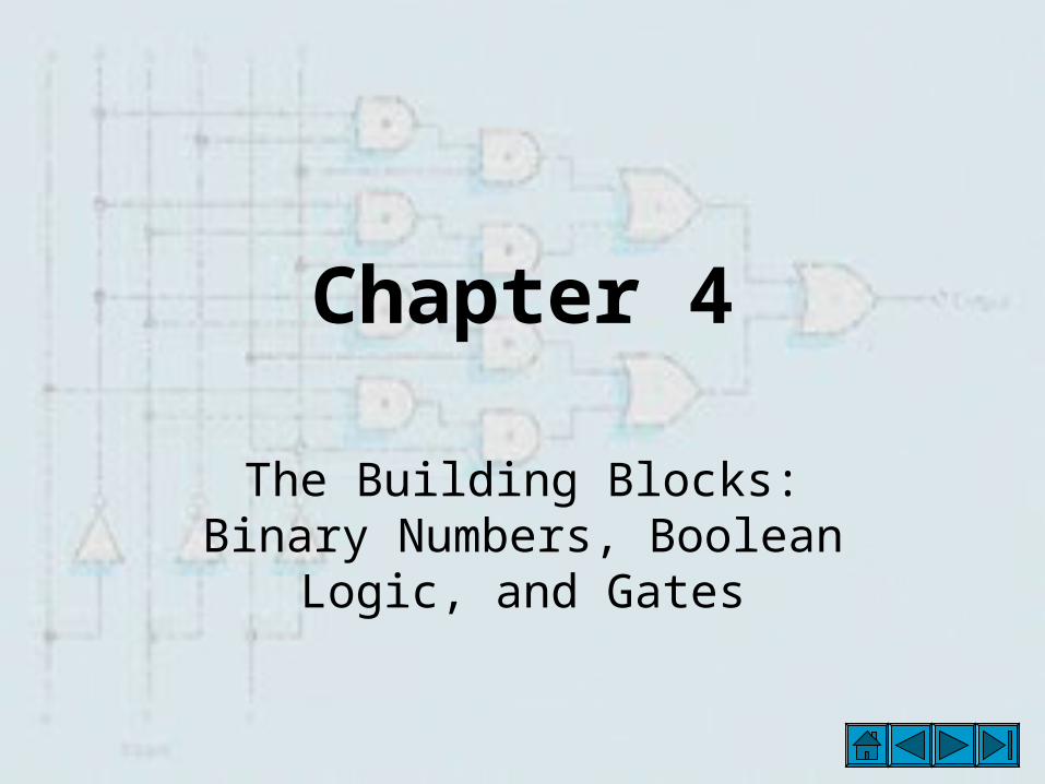
Figure 4.1 – The Binary Numbering System – Distinction Between the External and the Internal Representation of Information
The Binary Numbering System – Mantissa and Exponent
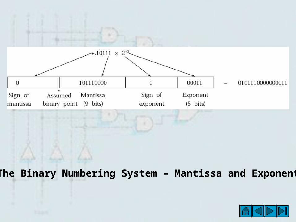
The Binary Numbering System – Mantissa and Exponent After Normalization
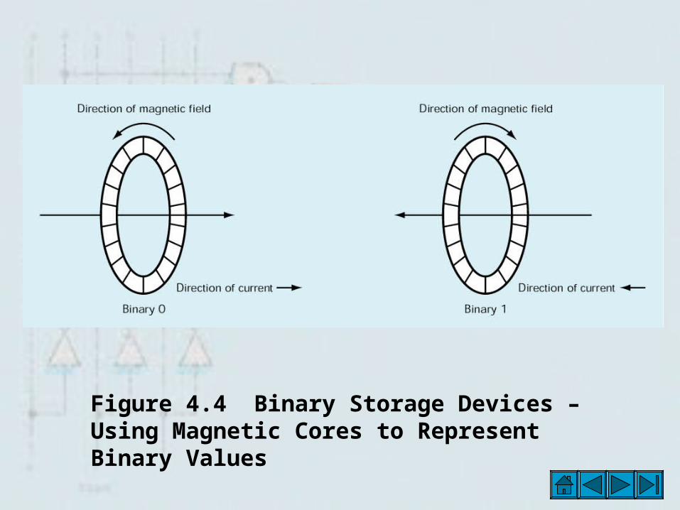
Figure 4.4 Binary Storage Devices – Using Magnetic Cores to Represent Binary Values

Binary Storage Devices – Figure 4.5 - Relationships Among Transistors, Chips and Circuit Boards

Figure 4. 6 Binary Storage devices – Simplified Model of a Transistor
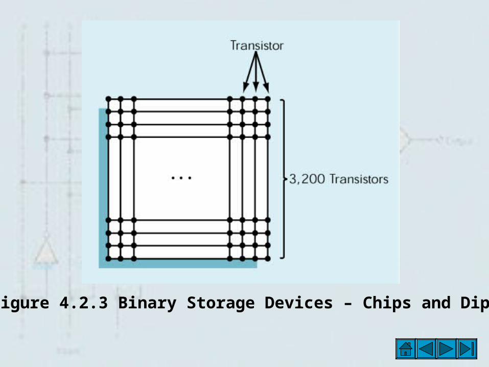
Figure 4.2.3 Binary Storage Devices – Chips and Dips
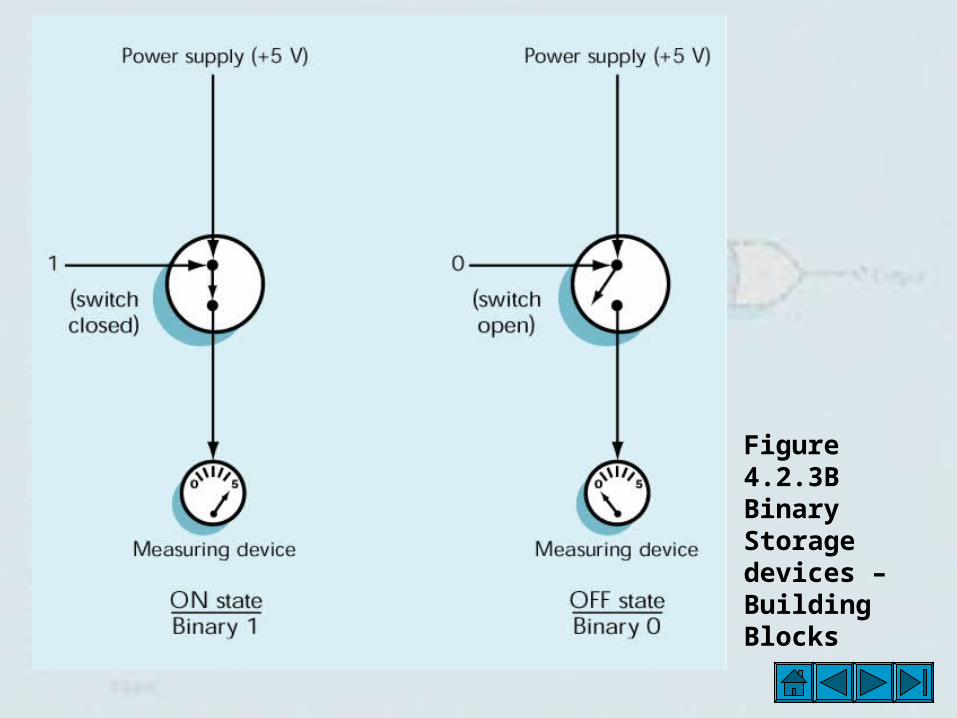
Figure 4.2.3B Binary Storage devices – Building Blocks
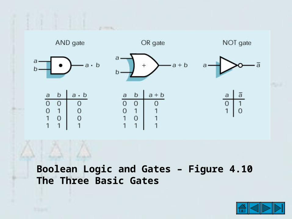
Boolean Logic and Gates – Figure 4.10 The Three Basic Gates
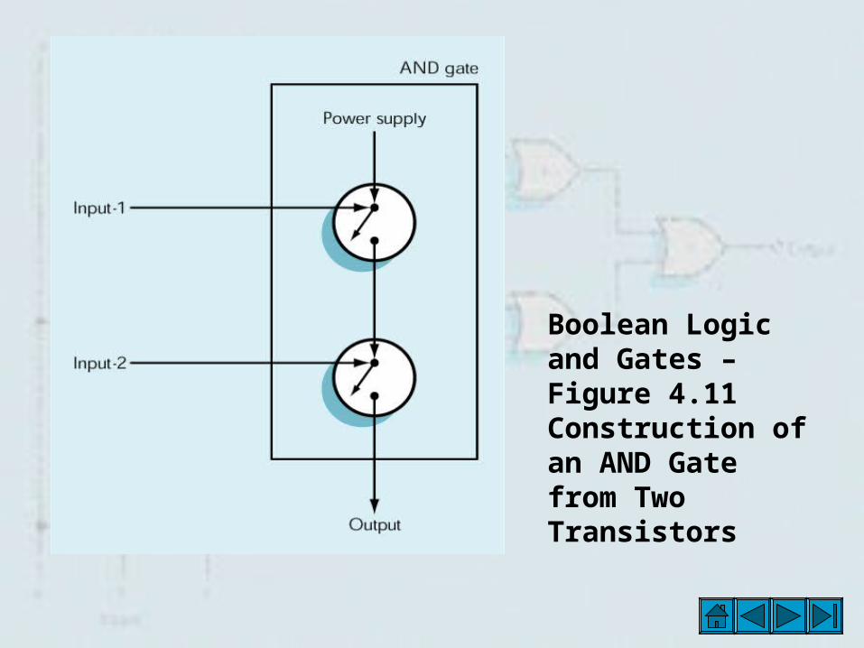
Boolean Logic and Gates – Figure 4.11 Construction of an AND Gate from Two Transistors
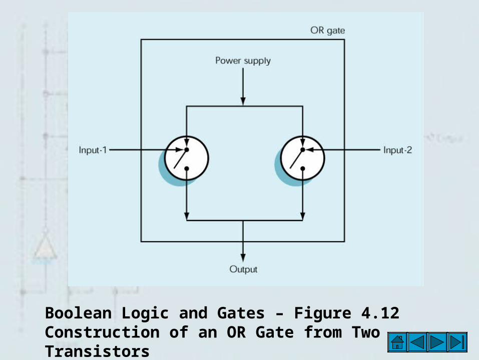
Boolean Logic and Gates – Figure 4.12 Construction of an OR Gate from Two Transistors
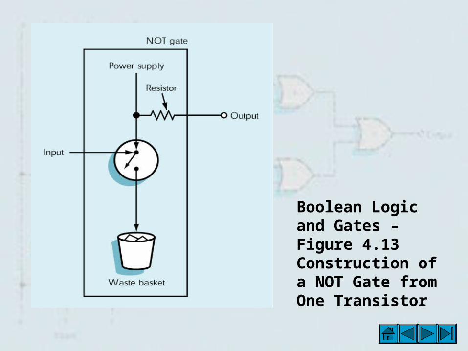
Boolean Logic and Gates – Figure 4.13 Construction of a NOT Gate from One Transistor
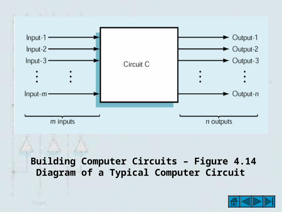
Building Computer Circuits – Figure 4.14 Diagram of a Typical Computer Circuit
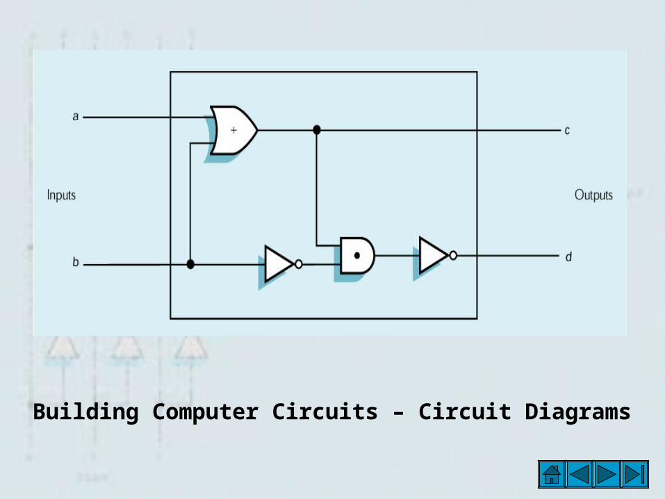
Building Computer Circuits – Circuit Diagrams

A Circuit Construction Algorithm – Figure 4.15 Circuit Diagram for the Output Labeled Output - 1
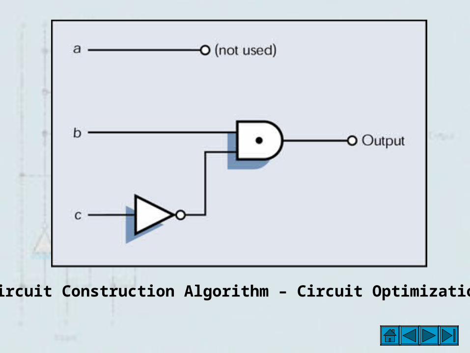
Circuit Construction Algorithm – Circuit Optimization
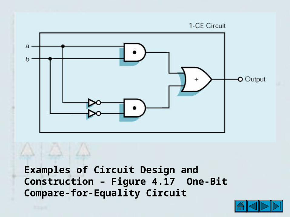
Examples of Circuit Design and Construction – Figure 4.17 One-Bit Compare-for-Equality Circuit
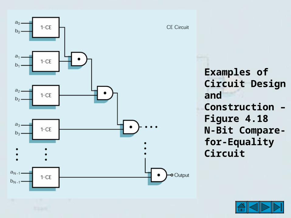
Examples of Circuit Design and Construction – Figure 4.18 N-Bit Compare-for-Equality Circuit
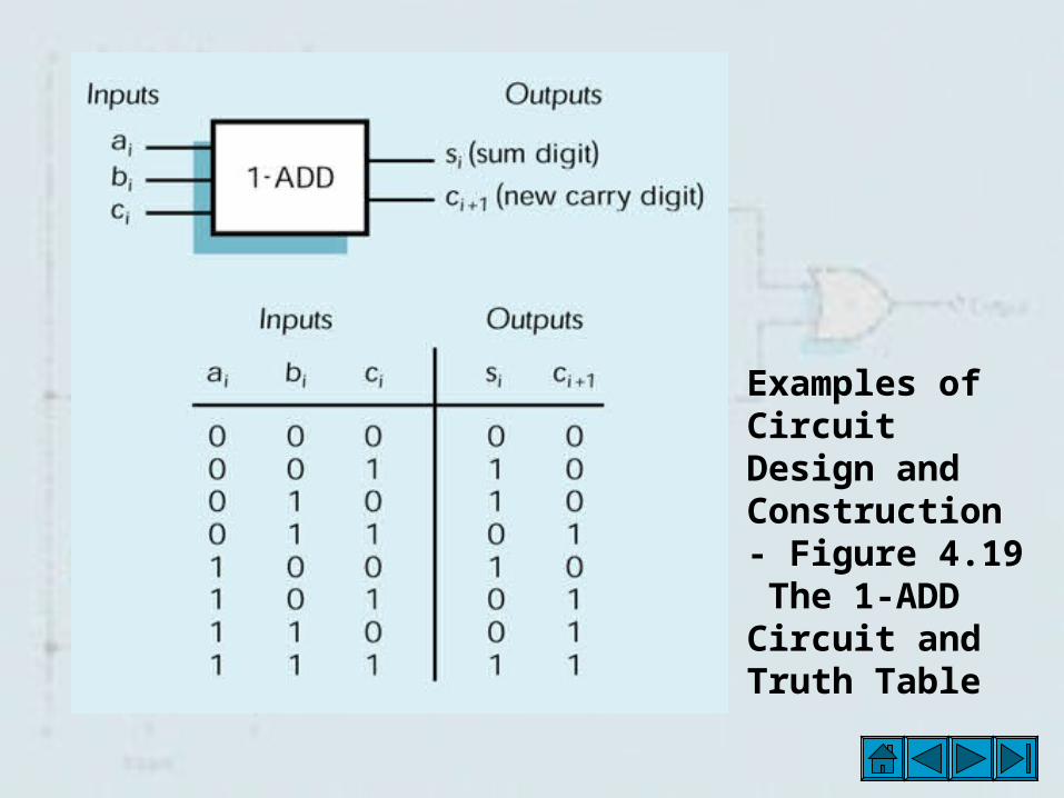
Examples of Circuit Design and Construction - Figure 4.19 The 1-ADD Circuit and Truth Table
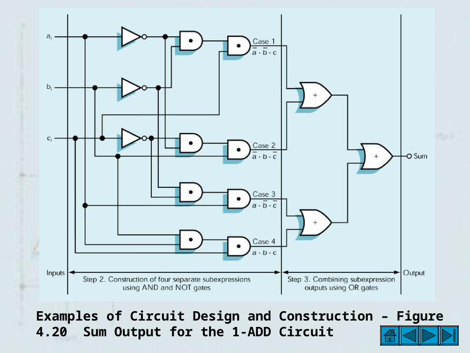
Examples of Circuit Design and Construction – Figure 4.20 Sum Output for the 1-ADD Circuit
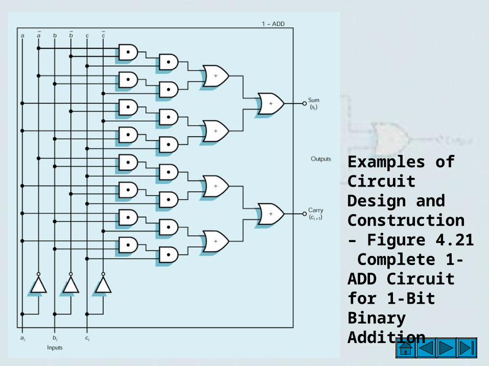
Examples of Circuit Design and Construction – Figure 4.21 Complete 1-ADD Circuit for 1-Bit Binary Addition
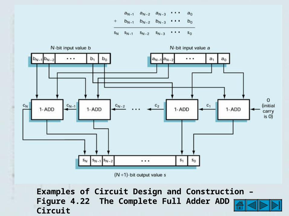
Examples of Circuit Design and Construction – Figure 4.22 The Complete Full Adder ADD Circuit
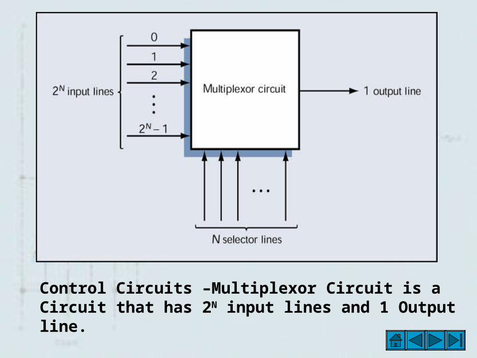
Control Circuits –Multiplexor Circuit is a Circuit that has 2N input lines and 1 Output line.
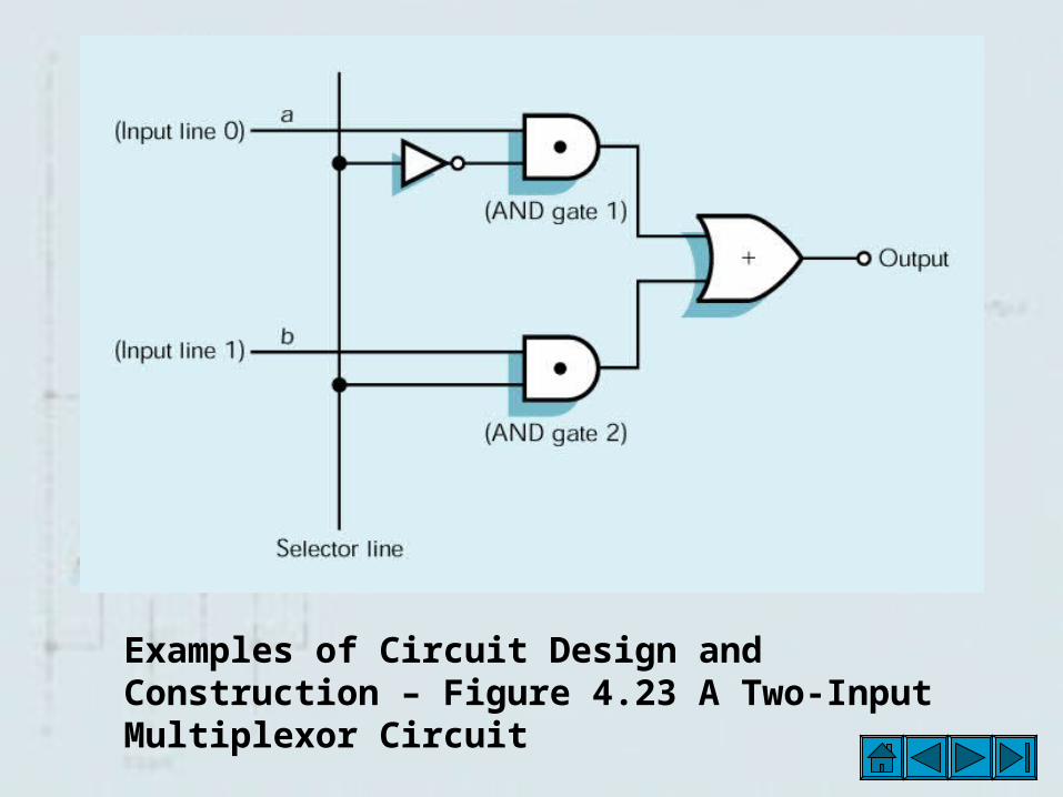
Examples of Circuit Design and Construction – Figure 4.23 A Two-Input Multiplexor Circuit
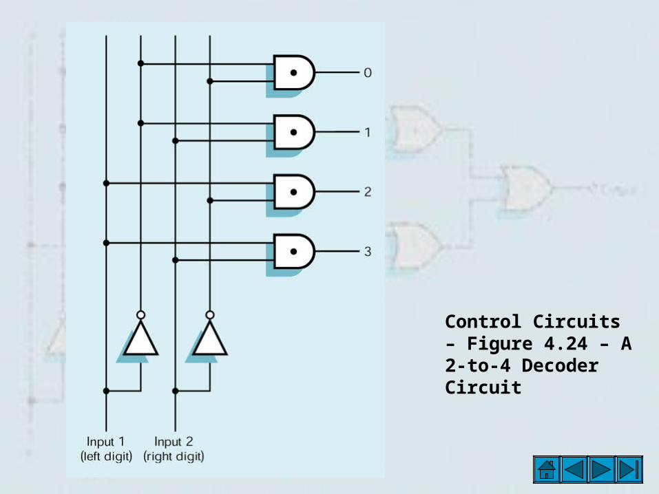
Control Circuits – Figure 4.24 – A 2-to-4 Decoder Circuit
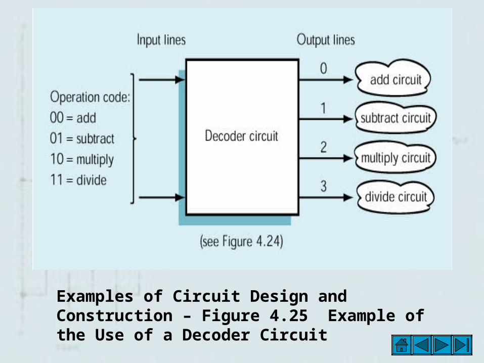
Examples of Circuit Design and Construction – Figure 4.25 Example of the Use of a Decoder Circuit
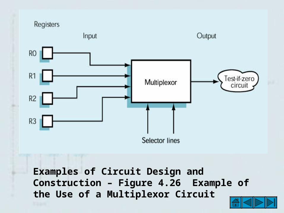
Examples of Circuit Design and Construction – Figure 4.26 Example of the Use of a Multiplexor Circuit