chapter 5 1. automating the test & evaluation process · 1. automating the test ......
TRANSCRIPT

CHAPTER 5 _______________________________________________________
1. Automating the Test & Evaluation Process
1.1 Introduction The automation of a process in general can be viewed as a formal method as described by
Minkowitz (1993), which has been exploited successfully for computer systems development.
Their use in the formulation of abstract and precise models of complex systems such as an
F/A-18 aircraft, makes them ideally suited to system specification and design.
The use of formal methods as argued by Vadera & Meziane (1994) in the development of
software has been advocated as a way of improving the reliability of software. A formal
development life-cycle begins with a formal specification. Design steps such as those
discussed in this chapter can then be proved with respect to their specification.
In actual fact the first step in the design process (Elliot, 1993) in which the broad route for all
of the detailed work that follows is mapped out is merely a systems engineering progression.
This means that it must take into account every aspect of the problem and every component of
the solution and must consider their interactions, and not just their individual properties.
In search for a methodology to automate the T&E process, the author carried out a
comprehensive literature search, as well as sending electronic mail and attending appropriate
seminars and conferences, to determine whether this task had been tackled in the past, looking
primarily at Australia and the United States. The outcome of this action is documented in the
following section.
1.2 Previous Automation Efforts in Australia and the USA As mentioned previously in chapter 2, research in the area of Test and Evaluation has been
confined to defence related agencies, and influenced by the United States of America
Department of Defence. According to the author’s knowledge, until now there has been no
1
Chapter 5 Automating the Test & Evaluation Process authentic published research related to the automation of Test and Evaluation Master Plans
for defence acquisition test programs, except for that of a tool developed by the Science
Applications International Corporation, more commonly addressed as SAIC, and funded by
the Office of the Under Secretary of Defence for Acquisition and Technology/Director, Test,
Systems Engineering & Evaluation (OUSD(A&T)/DTSE&E), as described by Roth (1995), in
the United States of America, known as The Automated Test Planning System.
1.2.1 Automated Test Planning System The Automated Test Planning System (ATPS) is a set of expert-system-based tools designed
to aid in the test and evaluation oversight process. The tools are particularly well suited to
staff members in the OUSD(A&T)/DT&E, and in the Department of Defence military service
components. The current ATPS concept envisions four modules (Roth, 1995):
♦ Test and Evaluation Master Plan Review,
♦ Test and Evaluation Program Risk Assessment (TEPRAM),
♦ TEMP Build, and
♦ Test and Evaluation Program Design.
ATPS has been developed in close cooperation with the Test and Evaluation Community
Network (TECNET). TECNET is a means of electronically exchanging unclassified
information between Test and Evaluation practitioners since 1983 (Hurlburt, 1992).
TECNET as well as ATPS release 4.5 for Windows® can be accessed and downloaded
respectively, from the World-Wide Web (WWW) via the following Internet address;
http1://atps.saic.com. Phase I of the development process resulted in a systems-of-systems
architecture as is shown in Figure 1-1, and a detailed system description.
1 http stands for Hypertext Transfer Protocol (an Internet protocol)
2

Chapter 5 Automating the Test & Evaluation Process
Automated Test PlanningSystem (ATPS)
TEMP ReviewModule
T&E ProgramDesign Module
Phase II
T&E ProgramRisk Assessment
Module
Phase III
TEMP BuildModule
Phase IV
HypertextGUI
TECNETResources
Knowledge basesDatabases
Figure 1-1 ( A system-of-systems architecture of the Automated Test Planning System (Roth,1995))
The PC-based ATPS demonstrates the generation of an intelligent checklist for TEMP review.
The body of knowledge was developed from representatives of United States DoD testing
organisations, existing paper checklists (Okagaki and Helmuth, 1993). The software is based
on the US DoD 500-series directives and instructions. In addition, the software accepts input
by the user (TEMP review comments) and transfers those comments to an ASCII file, which
can be read by a word processor for editing into a final report.
ATPS provides the user with a familiar Windows® (or Macintosh®) interface of buttons and
menus to interact with its specialised rule bases, hypertext, advisor, editor, and file services
(Roth, 1995). ATPS is a rule-based expert system (Okagaki and Ledesma, 1995) developed
in Rule-extended Algorithmic Language (RAL), an extension of the C programming
language, and encapsulates knowledge engineering and acquisition techniques, which are
defined by Okagaki and Helmuth (1993) as follows:
3
Chapter 5 Automating the Test & Evaluation Process
“Knowledge engineering is based on conceptualising the portion of an experts knowledge that a computer program must emulate.”
“Knowledge Acquisition; The expert system consists of a knowledge base and a inference engine. The knowledge base contains a set of highly independent rules that link information concerning a problem to draw a conclusion. The inference engine controls the reasoning strategy of the system and suggests the action to be taken. The knowledge that is developed into rules is derived from facts and from information gained through experience or observation.”
ATPS is an analysis tool, designed to aid the human analyst, not to replace technical thought.
It provides a standard baseline for TEMP development, risk assessment, and evaluation
(Okagaki and Ledesma, 1995).
1.2.2 Review of Specriter 3© and AutoSpec© Other more recent attempts to automate the generation of a process such as a plan, complying
to military standards or specifications, using a computer aided approach have been the work
of Cook (1991) and Evdokiou (1994), and the development of two software tools known as
Specriter 3© and AutoSpec© respectively.
Cook (1991) developed a computer tool to assist in the production of measuring instrument
specifications as part of his PhD entitled “A Knowledge-Based System for Computer-Aided
Generation of Measuring Instrument Specifications”. The aim of this research was to
produce a computer-assisted method of generating a measuring instrument requirements
specification from a requirements analysis. Specriter 3© is a computer aided engineering
package (Evdokiou, 1992) developed in Borland Prolog version 2.0, that employs knowledge
representation techniques (Cook, 1990) to produce a specification for a measuring instrument,
complying to US DoD MIL-STD-490A.
Evdokiou (1994) carried on the work by Cook (1991) with the development of a computer
design tool to assist in the cognitive aspect of extracting requirement specifications for
electronic systems, as part of his Masters Degree entitled “Computer Aided Generation of
Electronic Systems Requirements Specifications”. The aim of this research was to
conceptualise and develop a generic form of an electronic system such that descriptions of
function, behaviour and structure are used in the formulation of a requirement specification
template, and used as the basis for the subsequent automatic production of the initial
4

Chapter 5 Automating the Test & Evaluation Process requirements specifications documents (Evdokiou, 1994). AutoSpec© utilises Borland
ObjectVision 2.1 for Windows® for extraction and storage of the requirements requested from
the user, and Macros written in a document using Word 2.0 for Windows®, to automatically
link the databases containing the requirements of the customer (Evdokiou, 1994) and generate
a requirements specification document, complying to a type B1 USA MIL-STD-490A.
1.2.3 Review of T&E Plan Builder The United States Army Operational Test & Evaluation Command (OPTEC), along with the
University of Michigan has developed a similar type of automation software shell known as
the Test & Evaluation Plan (TEP) Builder.
The TEP (Wyatt & Ward, 1996) is a prototype automated system developed to assist
members of the Army T&E community in the key aspects of test planning such as the
development of evaluation strategies, data requirements, and test designs. The TEP Builder is
currently under construction and is being created to make OT&E both effective and
affordable by producing consistently high-quality planning documents in less time.
Wyatt & Ward also state that the actual time required to produce test plans can be greatly
reduced by eliminating redundant efforts. High-quality documents can be achieved by
promoting document consistency, implement training, and managing quality.
1.3 The Need for Automation In the past, in the Australian DoD, plans would be generated and products manufactured,
systems developed, using the concepts, theories, and practices of T&E, and it has only been
the last few years, more so since the birth of the Australian Centre for Test & Evaluation, that
the Australian DoD and respective T&E community realised the importance of this process,
and the importance to adhere to a master plan, a Test and Evaluation Master Plan (TEMP).
By regularly updating the TEMP from the genesis to the demise of a particular
product/system, it would prove to be the most vital part of any defence acquisition test
program, since it outlines strict critical issues, measures, and thresholds that all such test
programs should adhere to. Only in this fashion can the efficiency be increased, and the cost
and time of conducting tests be minimised, hence the need to automate the T&E process,
5

Chapter 5 Automating the Test & Evaluation Process namely, the TEMP, via the assistance of a computer has become apparent, and more so
viable.
The next section will deal with the why and how requirements are needed to fulfill the need
for automation, that is, the why and how of implementing requirements for the development of
a Computer Software Configuration Item or CSCI..
1.4 Requirements for Software Implementation The successful development of a large information system (Lalioti & Loucopoulos, 1994) is
dependent on the use of a pertinent method for identifying the requirements on the target
system and to make sure that the produced system will actually meet these requirements.
Broadly, the first step in Requirements Engineering (RE), is the acquisition step, in which has
the purpose of abstracting and conceptualising relevant parts of the application domain.
To begin with, one must first ascertain the requirements needed to automate the T&E process,
the analysis of requirements (Johnson et al, 1993) is a difficult, often error-prone process
because it relies on a wide range of domain and systems knowledge drawn from a variety of
individuals and organisations.
Duke & Harrison (1995) state that formal approaches to software development have been
mostly with problem descriptions that avoid expression of interactive behavior. However,
rigorous software development emphasises the demonstration that a program correctly
implements a specification, either through a process of verification or through the systematic
derivation of programs from specification to valid refinement transformations.
Duke & Harrison go on to say that, refinement is therefore concerned with the construction of
data structures and operations that are closer to the level of the machine that those in the
original problem description.
For complex systems in the US DoD, there are certain standards that computer assisted
systems should comply to, known as Computer-Aided Acquisition and Logistic Support or
CALS compliancy. DoD MIL-HDBK-59B (1990) is the primary document for CALS. The
primary goal of the CALS strategy is to migrate from manual, paper-intensive defence system
6

Chapter 5 Automating the Test & Evaluation Process operations to integrated, highly automated acquisition and support processes. The manual
also states that effective implementation of the CALS strategy is achieved by addressing the
following four elements throughout the life of a defence system:
1. Infrastructure for digital-based processes including computer hardware and software.
2. Process improvements in design, manufacturing and life cycle support.
3. Digital data acquisition.
4. Integrating technical data for use within weapon systems.
DeLauche and Reeves (1992) argue that the military services and DoD have developed
specific, but different, road maps to get to the computer environment of tomorrow. Agendas
differ relative to how CALS goals are reached. Surveys of the numerous automated support
systems of today have resulted in a multitude of recommendations for a CALS-oriented
support environment.
Within the US Armed Forces, a CALS Test Network (CTN) has been developed. The CTN
(Lammers, 1992) is a logical network, that is, the emphasis is on a linkage between
organisations to achieve objectives, rather than a physical telecommunications network. The
objectives of the CTN are to:
• Develop distributed testing capability
• Demonstrate the complete data delivery process
• Evaluate the effectiveness of the CALS Standards
• Evaluate new technology
Poorly defined requirements are a sure recipe for disaster when software is involved. As
described in IEEE STD 830-1984, characteristics of good software requirements are (Lacy,
1994) :
• Unambiguous
• Complete
• Verifiable
• Consistent
7

Chapter 5 Automating the Test & Evaluation Process • Modifiable
• Traceable
1.4.1 Software Requirement Specification Requirements for CSCI are often best described by a Software Requirement Specification,
also known as an SRS in the software world. DoD Instruction DI-IPSC-81433 (1994) states
that an SRS specifies the requirements for a CSCI and the methods to be used to ensure that
each requirement has been met. This is a CALS compliant document and comprehensive
guidelines for writing an SRS are contained within the Data Item Description or DID
mentioned above.
An SRS for the CSCI AutoTEMP© Beta 2.0, comprising of the following CSCIs: T&E
Information CSCI and Task Management CSCI, as described in Chapter 1 of this dissertation,
has been compiled and sanctioned by Mark Dvorak of the ACTE, who is the ARC
Collaborative Project Leader. The SRS is a fully endorsed eighteen page CALS compliant
document, the details of which can be located in Appendix V, where a copy of the SRS is
included in the Appendices section of this dissertation.
The SRS for the AutoTEMP© Beta 2.0 Software Shell2 was developed as a voluntary
addition, on the research work of the Flight Test Information Management System (FTIMS)
Heuristic Transaction Shell (HTS), as per Chapter 1, and was also compiled to illustrate the
natural progression of Software T&E documentation, the likes of which are as follows. The
next progression from this document would have been the development of a System Design
Description (SDD), had this been a software contract as opposed to a major research exercise.
Figure 1-2 illustrates this documentation process, that also acquires the purpose of
representing a requirements traceability document. The diagram shows how and where the
TEMP stands in this test documentation process, and was developed by the author to
demonstrate the future direction of the traceability in software requirements.
2 A tool developed by the author as a by-product of this research leading towards his Masters Degree.
8
Chapter 5 Automating the Test & Evaluation Process
SOR
TEMP
SDP SSDD
MNS FRS
SRS SDD STD STR
LEGEND
SOR Statement of Requirement
MNS Mission Need Statement
FRS Functional Requirement Specification
TEMP Test & Evaluation Master Plan
SDP Software Development Plan
SSDD Software Segment Design Document
SRS Software Requirement Specification
SDD Software Design Document
STD Software Test Document
STR Software Test Report
Figure 1-2 (Document Requirements Traceability Matrix)
As is evident from the diagram above, there is a lot of documentation for a particular
system/product that is in the process of procurement, and this type of software T&E does not
stop at any specific phase of the project, on the contrary, it continues right throughout the
entire process, the TEMP is continually updated and hence requirements are somewhat
“feedback” to the TEMP, for inclusion in the next update. A SSDD for the entire ARC
Collaborative project has been developed by the Project Leader, Mark Dvorak of the ACTE,
which outlines all four sub-research tasks as per chapter 1.
1.5 The Test & Evaluation Master Plan
1.5.1 Introduction In this section a Test & Evaluation Master Plan (TEMP) will be defined, its role in the
acquisition process, the US and Australian format will be presented and compared, and a
generic version encapsulating the best parts of both formats, but primarily based on the
Australian format will be defined and discussed comprehensively.
The United States has best described a TEMP for reasons mentioned previously in this
dissertation. There are a number of US specific authors that have defined a TEMP and its
9

Chapter 5 Automating the Test & Evaluation Process format, namely, Rodriguez (1992), Przemieniecki (1993), DSMC (1993), DSMC (1995),
Reynolds (1993), Reynolds & Damaan (1994), Dvorak and Equid (1994), and DoDI 5000.3-
M-2 (1990).
1.5.2 What is a TEMP Rodriguez (1992) defines a TEMP as an essential T&E document used by the Office of the
Secretary of Defence (OSD) to support milestone decisions by the Defence Acquisition Board
(DAB). The TEMP is the basic planning document for all T&E activity related to a
particular system acquisition. It defines both DT&E and OT&E associated with system
development and acquisition decisions. The TEMP relates program structure, decision
milestones, test management structure, and required resources to critical operational issues,
critical technical issues, evaluation criteria and procedures.
1.5.3 The Role of the TEMP In the early 1980’s, Reynolds (1993) states that the US DoD instituted the TEMP as the top
level T&E planning document to be used in each “major” program, i.e., those that would
come directly under the oversight of the Director of Operational T&E (DOT&E) and the
Under Secretary of Defence for Acquisition, T&E (USD(A)(T&E)). The Services had
adopted the use of the TEMP for lower level programs.
Dvorak and Equid (1994) states that the primary purpose of a TEMP is to establish a contract
between the Project Manager (PM), the appropriate Australian Defence Force (ADF) decision
maker, and the respective T&E agencies. The TEMP is essentially a living document that is
updated prior to each milestone to report T&E progress completed and to provide a revised
T&E plan for the next phase of activity. The TEMP is a multi-purpose document that:
• Enables the planning of test activities for demonstration of SPP’s and TPP’s,
• Details DT&E, PAT&E, and OT&E management structures and schedules,
• Provides a history of completed tests,
• Identifies critical performance parameters and operational issues,
• Provides a framework for generation of detailed test plans,
• Summarises required test resources, and
• Identifies new test resources.
10

Chapter 5 Automating the Test & Evaluation Process For DoD programs where DT&E and OT&E are very distinct, the TEMP for each program
combines both into an integrated master plan as is shown in Figure 1-3.
The TEMP documents the overall structure and objectives ofthe DATP. It provides a framework within which to generatedetailed T&E plans, and it documents schedule and resourceimplications associated with the T&E program. It relates:
Program Schedules
Test Management Strategy
Required Resources
Critical Operational Issues
Critical Technical Parameters
Required Operational Performance
Evaluation Criteria
Milestone Decision Points
TO
Figure 1-3 (Summary of the Purpose of a TEMP (based on Reynolds (1993))
The TEMP also documents a number of limitations in the DATP, more common types of
limitations appearing in TEMP’s are listed below (Reynolds & Damaan (1994):
• Cost
• Security Safety
• Ability to portray threat capabilities
• Ability to use full electromagnetic spectrum
• Test instrumentation
• Treaty constraints
• Available time
• Number and availability of test articles
• Test maneuver space
• Representative terrain
• Weather
11

Chapter 5 Automating the Test & Evaluation Process 1.5.4 Document Relationships Figure 1-4 illustrates how the TEMP interrelates with other key program documents. In
particular, the system performance requirements evolve from and expand upon those in the
Operational Requirement Document (ORD), which result from threat analysis and Cost
Effectiveness Analyses (CEA). This illustration is a merely an extension of Figure 1-2.
REQUIREMENTS DOCUMENTS
SPECIFICATIONS
CONTRACTOR’SDT&E PLANS
T&E MASTER PLAN
PROGRAM MANAGER’SDT&E PLANS
PROGRAM MANAGER’SOT&E PLANS
Figure 1-4 (TEMP Documentation Relationships (based on Reynolds (1993))
1.5.5 US TEMP Format The United States was the first body to document a standard and format for generating a
TEMP. This document was the Department of Defence Instruction 5000.3-M-1, first written
in 1986 and then later updated in 1990, any further revisions are not known to the author’s
knowledge. The US TEMP format is shown in Figure 1-5.
The DSMC (1993) states that the TEMP is a living document that must address changes to
critical issues associated with an DATP. Major changes in program requirements, schedule or
funding usually result in a change in the test program. Thus, the TEMP must be reviewed and
updated on program change, on baseline breach and before each milestone decision, to ensure
that T&E requirements are current.
12

Chapter 5 Automating the Test & Evaluation Process
PART I SYSTEM INTRODUCTION (2 pages suggested) Mission Description System Description Critical Technical Characteristics Required Operational Characteristics PART II PROGRAM SUMMARY (2 pages suggested) Integrated Schedule Management PART III DT&E OUTLINE (10 pages suggested) DT&E Overview DT&E to Date Future DT&E Special DT&E Topics LFT&E PART IV OT&E Outline (10 pages suggested) OT&E Overview Critical Operational Issues OT&E to Date Future OT&E PART V T&E Resource Summary (6 pages suggested) Summary Test Articles Test Sites and Instrumentation Test Support Equipment Threat Systems/Simulators Test Targets and Expendables Operational Force Test Support Simulations, Models and Testbeds Special Requirements T&E Funding Requirements Manpower/Training Key Resources APPENDIX A BIBLIOGRAPHY APPENDIX B ACRONYMS APPENDIX C POINTS OF CONTACT
Figure 1-5 (US TEMP Format (adopted from DoD 5000.3-M-1))
1.5.6 The Australian TEMP Format In the Australian Defence Force, the underlying document that provides any related T&E
guidance is the Capital Equipment Procurement Manual (CEPMAN 1) (Australian DoD,
1995), which outlines the conduct of test & evaluation in support of capital equipment
projects.
13

Chapter 5 Automating the Test & Evaluation Process Chapter 14, part 2, of this manual contains a brief overview of the requirements for the
planning and conduct of test and evaluation to be performed by defence during projects in
order to obtain factual data to assist in validating new or upgraded equipment. The manual
states that organisations with responsibility for the design approval, certification or
procurement of equipment have the authority and responsibility to conduct (or require the
conduct of) T&E. All project T&E requirements are to be coordinated by the project
manager, who should consider whether or not T&E can be conducted within available project
resources and if it is preferable to seek assistance of an external agency to conduct or assist in
conducting such T&E.
The manual also states that project manager, in consultation with operational, technical and
maintenance authorities, is to fully investigate the necessity for, and likely scope of, Defence
T&E. If a requirement exists for the conduct of T&E, its scope is to be documented in a Test
& Evaluation Master Plan (TEMP) at the earliest possible stage in the project planning
process. Annex B of the manual, details the role, content and format of a TEMP, and TEMP
writer’s guide is in Annex C.
A description of the Australian TEMP format is detailed in the author’s software
AutoTEMP©, beta version 2.0, in the form of a hypertext interactive software tutorial. This
tutorial is the first of three software modules that make up AutoTEMP© and its
hypertextability and human-computer interactivity as well as a detailed description is dealt
with in more detail in chapter 6. For this reason, the proceeding description will merely give
an outline of the TEMP format, and any detail that is not dealt with in the tutorial. The
generic table of contents is shown in Figure 1-6.
14

Chapter 5 Automating the Test & Evaluation Process
1. SECTION I - DESCRIPTION
1.1. MISSION 1.1.1. Operational Need 1.1.2. Mission to be accomplished 1.1.3. Specified Environment
1.2. SYSTEM 1.2.1. Key Functions 1.2.2. Interfaces 1.2.3. Unique Characteristics
1.3. REQUIRED OPERATIONAL CHARACTERISTICS 1.3.1. Key Operational Effectiveness Characteristics 1.3.2. Key Suitability Characteristics 1.3.3. Thresholds
1.4. REQUIRED TECHNICAL CHARACTERISTICS 1.4.1. Key Technical Characteristics 1.4.2. Performance Objectives 1.4.3. Thresholds
1.5. CRITICAL T&E ISSUES 1.5.1. DT&E Critical Issues 1.5.2. OT&E Critical Issues 1.5.3. S3 Critical Issues
2. SECTION II - PROGRAM SUMMARY
2.1. MANAGEMENT ASPECTS 2.2. INTEGRATED SCHEDULE 2.3. FUNDING ASPECTS OF THE T&E PROCESS
3. SECTION III - DT&E OUTLINE
3.1. DT&E TO DATE 3.1.1. Summary of DT&E already Conducted 3.1.2. Difference for Plan 3.1.3. DT&E Events and Results
3.2. FUTURE DT&E 3.2.1. Equipment Description 3.2.2. DT&E Objectives 3.2.3. Limitations of Scope 3.2.4. Test Failure Procedures
3.3. CRITICAL DT&E ITEMS 3.3.1. Equipment Used
4. SECTION IV - OT&E OUTLINE
4.1. OT&E TO DATE 4.1.1. Summary of OT&E Date 4.1.2. Test Schedules 4.1.3. OT&E Events and Results
4.2. FUTURE OT&E 4.2.1. Equipment Description 4.2.2. OT&E Objectives 4.2.3. OT&E Events/Scope of Testing/Basic Scenarios
4.3. CRITICAL OT&E ITEMS 4.3.1. Highlights
5. SECTION V - PRODUCTION ACCEPTANCE T&E (PAT&E)
5.1. PAT&E TO DATE 5.1.1. Summary of PAT&E to Date 5.1.2. Test Schedules
15

Chapter 5 Automating the Test & Evaluation Process
5.1.3. PAT&E Events and Results 5.2. FUTURE PAT&E
5.2.1. Equipment Description 5.2.2. PAT&E Objectives 5.2.3. PAT&E Events/Scope of Testing
5.3. CRITICAL PAT&E ITEMS 5.3.1. Highlights
6. SECTION VI - SAFETY AND SUITABILITY FOR SERVICE (S3)
6.1. FEATURES 6.2. EQUIPMENT 6.3. SYSTEMS SAFETY PROGRAM 6.4. S3 EVALUATION
6.4.1. Descriptive Proceeding 6.4.2. A Laying-on Proceeding 6.4.3. A Reporting Proceeding
7. SECTION VII - SPECIAL RESOURCE SUMMARY
7.1. TEST SCHEDULES 7.2. INSTRUMENTATION
7.2.1. Targets 7.2.2. Threat Simulations 7.2.3. Test Sites 7.2.4. Facilities 7.2.5. Support
8. APPENDIX A - POINTS OF CONTACT
9. APPENDIX B - NOMENCLATURE
10. APPENDIX C - REFERENCED DOCUMENTS
Figure 1-6 (CEPMAN 1 TEMP Format (based on Australian DoD, 1995))
1.5.7 Comparison of US and Australian TEMP Format Table 1-1 summarises the difference between the US DoD 5000.3-M-1 and the Australian
DoD CEPMAN 1 TEMP format. As is evident the US format does not detail PAT&E and
Systems, Safety and Service (S3) as the Australian format does.
16

Chapter 5 Automating the Test & Evaluation Process
US DoD 5000.3-M-1 AUSTRALIAN DoD CEPMAN 1
Part I - System Introduction Section I - Description
Part II - Program Summary Section II - Program Summary
Part III - DT&E Outline Section III - DT&E Outline
Part IV - OT&E Outline Section IV - OT&E Outline
Section V - PAT&E Summary
Section VI - S3 Evaluation
Part V - T&E Resource Summary Section VII - Special Resource Summary
Appendix A - Bibliography Appendix A - Bibliography
Appendix B - Acronyms Appendix B - Acronyms
Appendix C - Point of Contact Appendix C - Point of Contact
Appendix D - User Information Matrix
Table 1-1 (The US DoD 5000.3-M-1 and Australian DoD CEPMAN 1 TEMP Format Compared)
The US denotes the sections of the TEMP with the terminology “Parts”, and the Australia has
adopted “Sections”, of which there are five and seven respectively. The PAT&E and S3
sections are excluded. PAT&E is considered an element of DT&E in the US system. The S3
functions are examined by both the OT and DT communities.
1.5.8 Australian Conceptual TEMP Format As mentioned previously, the author has conceptualised a generic format of the TEMP
contents, which is primarily based on CEPMAN 1 but with modifications and additions with
the help of the US TEMP format and other literature mentioned in section 5.5.1 previously.
This conceptualisation is depicted in Figure 1-7 overpage.
17
Chapter 5 Automating the Test & Evaluation Process
1. SECTION I - DESCRIPTION
1.1 DOCUMENT DESCRIPTION 1.2 MISSION DESCRIPTION
1.2.1 Operational Need 1.2.2 Mission to be accomplished 1.2.3 Specified Environment
1.3 SYSTEM DESCRIPTION 1.3.1 Key Functions 1.3.2 Interfaces 1.3.3 Unique Characteristics
1.4 REQUIRED OPERATIONAL CHARACTERISTICS 1.4.1 Key Operational Effectiveness Characteristics 1.4.2 Key Suitability Characteristics 1.4.3 Thresholds
1.5 REQUIRED TECHNICAL CHARACTERISTICS 1.5.1 Key Technical Characteristics 1.5.2 Performance Objectives 1.5.3 Thresholds
1.6 CRITICAL T&E ISSUES 1.6.1 DT&E Critical Issues 1.6.2 OT&E Critical Issues 1.6.3 S3 Critical Issues
2. SECTION II - PROGRAM SUMMARY
2.1 MANAGEMENT ASPECTS 2.2 INTEGRATED SCHEDULE 2.3 FUNDING ASPECTS OF THE T&E PROCESS
3. SECTION III - DT&E OUTLINE
3.1 DT&E TO DATE 3.1.1 Summary of DT&E already Conducted 3.1.2 Difference for Plan 3.1.3 DT&E Events and Results
3.2 FUTURE DT&E 3.2.1 DT-I
3.2.1.1 Configuration Description 3.2.1.2 DT&E Objectives 3.2.1.3 DT&E Events 3.2.1.4 Limitations to Scope
3.2.2 DT-II TECHEVAL 3.2.2.1 Configuration Description 3.2.2.2 DT&E Objectives 3.2.2.3 DT&E Events 3.2.2.4 Limitations to Scope
3.2.3 Test Failure Procedures 3.3 CRITICAL DT&E ITEMS
3.3.1 Equipment Used
4. SECTION IV - OT&E OUTLINE
4.1 OT&E TO DATE 4.1.1 OT-I EOA 4.1.2 OT-II OPEVAL 4.1.3 Summary of OT&E Date 4.1.4 Test Schedules 4.1.5 OT&E Events and Results
4.2 FUTURE OT&E 4.2.1 OT-I EOA
18

Chapter 5 Automating the Test & Evaluation Process
4.2.1.1 Configuration Description 4.2.1.2 OT&E Objectives 4.2.1.3 OT&E Events 4.2.1.4 Limitations to Scope
4.2.2 OT-II OPEVAL 4.2.2.1 Configuration Description 4.2.2.2 OT&E Objectives 4.2.2.3 OT&E Events
4.2.2.3.1 Scenarios 4.2.2.4 Limitations to Scope
4.2.3 OT-III FOT&E 4.2.3.1 Configuration Description 4.2.3.2 OT&E Objectives 4.2.3.3 OT&E Events 4.2.3.4 Limitations to Scope
4.3 CRITICAL OT&E ITEMS 4.3.1 Effectiveness Issues
4.3.1.1 Document Generation 4.3.1.2 Traceability 4.3.1.3 Future Growth
4.3.2 Suitability Issues 4.3.2.1 Availability 4.3.2.2 Compatibility 4.3.2.3 Transportability 4.3.2.4 Interoperability 4.3.2.5 Reliability 4.3.2.6 Wartime Usage Rates 4.3.2.7 Maintainability 4.3.2.8 Safety 4.3.2.9 Human Factors 4.3.2.10 Manpower Supportability 4.3.2.11 Logistics Supportability 4.3.2.12 Documentation 4.3.2.13 Training Requirements
4.3.3 Highlights
5. SECTION V - PRODUCTION ACCEPTANCE T&E (PAT&E)
5.1 PAT&E TO DATE 5.1.1 Summary of PAT&E to Date 5.1.2 Test Schedules 5.1.3 PAT&E Events and Results
5.2 FUTURE PAT&E 5.2.1 Equipment Description 5.2.2 PAT&E Objectives 5.2.3 PAT&E Events/Scope of Testing
5.3 CRITICAL PAT&E ITEMS 5.3.1 Highlights
6. SECTION VI - SAFETY AND SUITABILITY FOR SERVICE (S3)
6.1 FEATURES 6.2 EQUIPMENT 6.3 SYSTEMS SAFETY PROGRAM 6.4 S3 EVALUATION
6.4.1 Descriptive Proceeding 6.4.2 A Laying-on Proceeding 6.4.3 A Reporting Proceeding
7. SECTION VII - SPECIAL RESOURCE SUMMARY
7.1 TEST SCHEDULES 7.2 SPECIAL SUPPORT REQUIREMENTS
7.2.1 Instrumentation
19
Chapter 5 Automating the Test & Evaluation Process
7.2.2 Targets 7.2.3 Threat Simulations 7.2.4 Test Sites 7.2.5 Facilities 7.2.6 Support
8. APPENDIX A
8.1 POINTS OF CONTACT
9. APPENDIX B
9.1 NOMENCLATURE
10. APPENDIX C
10.1 REFERENCED DOCUMENTS
11. APPENDIX D
11.1 USER INFORMATION MATRIX
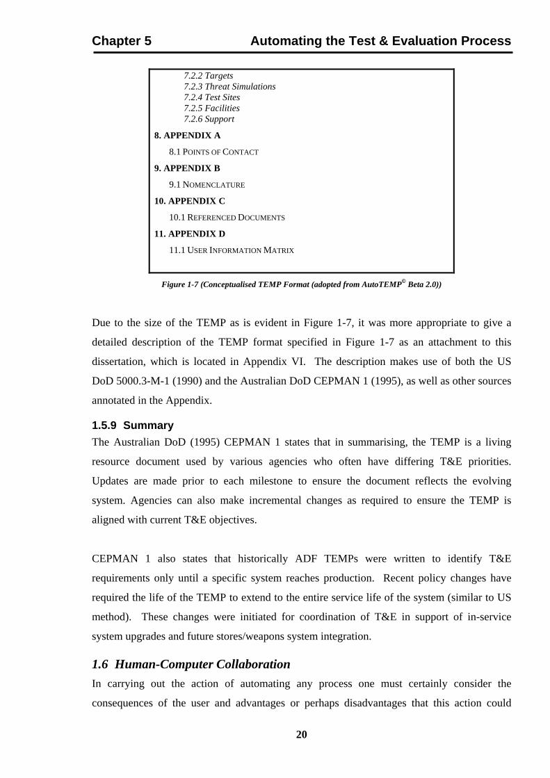
Figure 1-7 (Conceptualised TEMP Format (adopted from AutoTEMP© Beta 2.0))
Due to the size of the TEMP as is evident in Figure 1-7, it was more appropriate to give a
detailed description of the TEMP format specified in Figure 1-7 as an attachment to this
dissertation, which is located in Appendix VI. The description makes use of both the US
DoD 5000.3-M-1 (1990) and the Australian DoD CEPMAN 1 (1995), as well as other sources
annotated in the Appendix.
1.5.9 Summary The Australian DoD (1995) CEPMAN 1 states that in summarising, the TEMP is a living
resource document used by various agencies who often have differing T&E priorities.
Updates are made prior to each milestone to ensure the document reflects the evolving
system. Agencies can also make incremental changes as required to ensure the TEMP is
aligned with current T&E objectives.
CEPMAN 1 also states that historically ADF TEMPs were written to identify T&E
requirements only until a specific system reaches production. Recent policy changes have
required the life of the TEMP to extend to the entire service life of the system (similar to US
method). These changes were initiated for coordination of T&E in support of in-service
system upgrades and future stores/weapons system integration.
1.6 Human-Computer Collaboration In carrying out the action of automating any process one must certainly consider the
consequences of the user and advantages or perhaps disadvantages that this action could
20

Chapter 5 Automating the Test & Evaluation Process impose. Terveen (1995) defines Collaboration as “a process in which two or more agents
work together to achieve shared goals”. Terveen also states that the study of Human-
Computer Collaboration (HCC) is highly disciplinary. Its two basic parent disciplines are
Artificial Intelligence (AI) and Human-Computer Interaction (HCI). AI draws knowledge
representation and reasoning techniques, and HCI draws interaction and information
presentation techniques.
Rogers (1995) states that the enhancement of human performance in complex tasks is an issue
which has long concerned researchers, particularly with respect to the role of automation. He
goes on to say that, in order to build effective human-machine cognitive systems, techniques
and concepts are needed to identify the decision-making/problem-solving requirements in
some domain.
The US Army on the other hand, states that (Banister, 1995) the materiel acquisition process
is replete with procedures, processes, and policies designed to eliminate or reduce the
uncontrollable human variable in all phases of the weapons system acquisition process,
defined in chapter 4. Both disciplines however, Software Engineering (SE) and HCI need
ways of measuring how well their products and development processes fulfill their intended
requirements, as argued by Preece & Rombach (1994).
Bishop (1994) states that the OPTEC has provided its operational evaluators and analysts to
assess the user friendliness of computer software with the development of a guide known as
“Handbook for the Evaluation of User Friendliness of Soldier-System Interfaces”, in which its
goal in life is “to quantify system user friendliness across the full range of subjective and
objective data obtained from users, and others, who are familiar with a given system.”
Thus, the author has designed the software shell AutoTEMP©, that is described in the
proceeding chapter, used to assist the user (human) in generating a TEMP, so that there is
some degree of user-computer friendly interaction. This consideration merely adds more
thorough software T&E of the system at hand, and hence an increase in efficiency, and
reliability.
21

Chapter 5 Automating the Test & Evaluation Process 1.7 Conclusion This chapter has looked at the automation of the T&E process, in which a review of previous
work such as, The Automated Test Planning System, Specriter 3©, and AutoSpec©, by the
Science Applications International Corporation, Cook (1991) and Evdokiou (1994)
respectively, was discussed, along with the need for and requirements for its automation.
The importance of adhering to and regularly updating a TEMP was emphasised as the most
vital part of any defence acquisition test program, due to the fact that it outlines very crucial
elements and parameters that all such test should aspire to, and only in this fashion can the
cost and time of conducting a test be reduced and efficiency subsequently increased, via the
assistance of a computer in automating this process.
The chapter then concluded with a comprehensive discussion of TEMP’s, outlining the
formats used by the United States and Australia, its role, and its conceptualisation into a
generic form or template, along with a brief discussion on the collaboration between the
software and the user operating it.
The next chapter will give an insight into the by-product of this research, namely, a detailed
look at AutoTEMP© Beta 2.0, and its operation, via a breakdown of its three interlaced
modules.
22