chapter 5 engine electrical systems - podolsk.rucx.podolsk.ru/xm/docum/haynes_zx/zx-05.pdf ·...
TRANSCRIPT
5•1
Chapter 5 Engine electrical systemsContentsAlternator - removal and refitting 13Alternator brushes and regulator - inspection and renewal 14Alternator drivebelt - removal, refitting and tensioning 12Battery - removal and refitting 4Battery - testing and charging 3Battery check See Chapter 1Charging system - testing 11Distributor - removal and refitting 8Electrical fault finding - general information 2Electrical system check See Chapter 1General information and precautions 1Ignition HT coil(s) - removal, testing and refitting 7
Degrees of difficulty
Ignition switch - removal and refitting 18Ignition system - general information 5Ignition system - testing 6Ignition system amplifier unit(s) - removal and refitting 9Ignition timing - checking and adjustment 10Oil level sensor - removal and refitting 20Oil pressure warning light switch - removal and refitting 19Oil temperature sensor - removal and refitting 21Starter motor - brush renewal 17Starter motor - removal and refitting 16Starting system - testing 15
Easy, suitable fornovice with littleexperience
Fairly easy, suitablefor beginner withsome experience
Fairly difficult, suitablefor competent DIYmechanic
Difficult, suitable forexperienced DIYmechanic
Very difficult,suitable for expert DIYor professional
SpecificationsSystem type 12-volt, negative earth
BatteryType Lead acidMake Fulmen, Delco or StecoCharge condition:
Poor 12.5 voltsNormal 12.6 voltsGood 12.7 volts
Ignition systemSystem type*:
1124 cc models, and 1360 cc (K2D and KDY engine) models Breakerless electronic, with distributor1360 cc (KDX engine) models Static (distributorless) system, controlled by engine management
ECU1580 cc, 1761 cc, 1905 cc (D6E engine) and 1998 cc 8-valve models Static (distributorless) system controlled by engine management
ECU1905 cc (DKZ engine) models Distributor-type system, control led by engine management ECU1998 cc 16-valve models Static (distributorless) "sequential" system, controlled by engine
management ECU*Refer to text for further information on each system

5•2 Engine electrical systems
Ignition system (continued)Firing order 1-3-4-2 (No 1 cylinder at transmission end of engine)Ignition timing:
1124 cc models, and 1360 cc (K2D and KDY engine) models 8° BTDC @ 750 rpmAll other models Controlled by ECU - see text
Ignition HT coil resistances*:1124 cc models, and 1360 cc (K2D and KDY engine) models:
Primary windings 0.8 ohmsSecondary windings 6500 ohms
1360 cc (KDX engine) models N/A1580 cc and 1905 cc models:
Primary windings 0.8 ohmsSecondary windings - Bosch coil 14 600 ohmsSecondary windings - Valeo coil 8600 ohms
1761 cc models N/A1998 cc 8-valve models:
Primary windings - Bosch coil 0.5 ohmsPrimary windings - Valeo coil 0.8 ohmsSecondary windings N/A
1998 cc 16-valve models:Primary windings 0.65 ohmsSecondary windings N/A
'Values given are accurate only when the coil is at 20°C. Where no values are quoted, refer to your Citroen dealer for advice. See text for furtherinformation.
AlternatorType Valeo, Bosch or Mitsubishi
Starter motor
Type Valeo or Bosch
General informationThe engine electrical system includes all
charging, starting and ignition systemcomponents. Because of their engine-relatedfunctions, these components are coveredseparately from the body electrical devicessuch as the lights, instruments, etc (which arecovered in Chapter 12).
The electrical system is of the 12-voltnegative earth type.
The battery is of the low-maintenance or"maintenance-free" ("sealed for life") type,and is charged by the alternator, which is belt-driven from the crankshaft pulley. •
The starter motor is of the pre-engagedtype, incorporating an integral solenoid. Onstarting, the solenoid moves the drive pinioninto engagement with the flywheel ring gearbefore the starter motor is energised. Oncethe engine has started, a one-way clutchprevents the motor armature being driven bythe engine until the pinion disengages fromthe flywheel.
Refer to Section 5 for further information onthe various ignition systems.
PrecautionsFurther details of the various systems are
given in the relevant Sections of this Chapter.While some repair procedures are given, theusual course of action is to renew the
component concerned. The owner whoseinterest extends beyond mere componentrenewal should obtain a copy of the"Automobile Electrical & Electronic SystemsManual", available from the publishers of thismanual.
It is necessary to take extra care whenworking on the electrical system, to avoiddamage to semi-conductor devices (diodesand transistors), and to avoid the risk ofpersonal injury. In addition to the precautionsgiven in "Safety first!" at the beginning of thismanual, observe the following when workingon the system.
Always remove rings, watches, etc beforeworking on the electrical system. Even withthe battery disconnected, capacitivedischarge could occur if a component's liveterminal is earthed through a metal object.This could cause a shock or nasty burn.
Do not reverse the battery connections.Components such as the alternator, fuelinjection electronic control unit, or any othercomponents having semi-conductor circuitry,could be irreparably damaged.
If the engine is being started using jumpleads and a slave battery, connect thebatteries positive-to-positive and negative-to-negative (see "Booster battery (jump)starting"). This also applies when connectinga battery charger.
Never disconnect the battery terminals, thealternator, any electrical wiring or any testinstruments when the engine is running.
Do not allow the engine to turn the alternatorwhen the alternator is not connected.
Never "test" for alternator output by"flashing" the output lead to earth.
Never use an ohmmeter of the typeincorporating a hand-cranked generator forcircuit or continuity testing.
Always ensure that the battery negativelead is disconnected when working on theelectrical system.
Before using electric-arc weldingequipment on the car, disconnect the battery,alternator and components such as the fuelinjection/ignition electronic control unit, toprotect them from the risk of damage.
The radio/cassette unit fitted as standardequipment by Citroen is equipped with a built-in security code, to deter thieves. If the powersource to the unit is cut, the anti-theft systemwill activate. Even if the power source isimmediately reconnected, the radio/cassetteunit will not function until the correct securitycode has been entered. Therefore, if you donot know the correct security code for theradio/cassette unit, do not disconnect thebattery negative terminal of the battery, orremove the radio/cassette unit from thevehicle. Refer to "Radio/cassette unit anti-theft system precaution" Section at thebeginning of this manual for details of how toenter the security code.
Refer to Chapter 12, Section 2.
1 General information andprecautions
2 Electrical fault finding -general information
Engine electrical systems 5•3
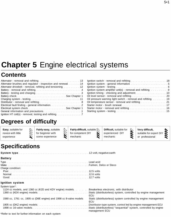
3.1 Using a hydrometer to check thebattery electrolyte specific gravity
3 Battery - testing and charging
Standard and low-maintenancebattery - testing1 If the vehicle covers a small annual mileage,it is worthwhile checking the specific gravityof the electrolyte every three months, todetermine the state of charge of the battery.Use a hydrometer (these are readily-availablefrom motor accessory outlets) to make thecheck, and compare the results with thefollowing table (see illustration). Note thatthe specific gravity readings assume anelectrolyte temperature of 15°C (60°F); forevery 10°C (18°F) below 15°C (60°F), subtract0.007. For every 10°C (18°F) above 15°C(60°F), add 0.007.
Ambient Ambienttemperature temperatureabove 25°C below 25°C(77°F) (77°F)
Fully-charged 1.210 to 1.230 1.270 to 1.29070% charged 1.170 to 1.190 1.230 to 1.250Fully-discharged 1.050 to 1.070 1.110 to 1.1302 If the battery condition is suspect, firstcheck the specific gravity of electrolyte ineach cell. A variation of 0.040 or morebetween any cells indicates loss of electrolyteor deterioration of the internal plates.3 If the specific gravity variation is 0.040 ormore, the battery should be renewed. If thecell variation is satisfactory but the battery isdischarged, it should be charged asdescribed later in this Section.
Maintenance-free battery -testing4 In cases where a "sealed for life"maintenance-free battery is fitted, topping-upand testing of the electrolyte in each cell is notpossible. The condition of the battery cantherefore only be tested using a batterycondition indicator or a voltmeter.5 Certain models my be fitted with a "Delco"type maintenance-free battery, with a built-incharge condition indicator. The indicator islocated in the top of the battery casing, andindicates the condition of the battery by its
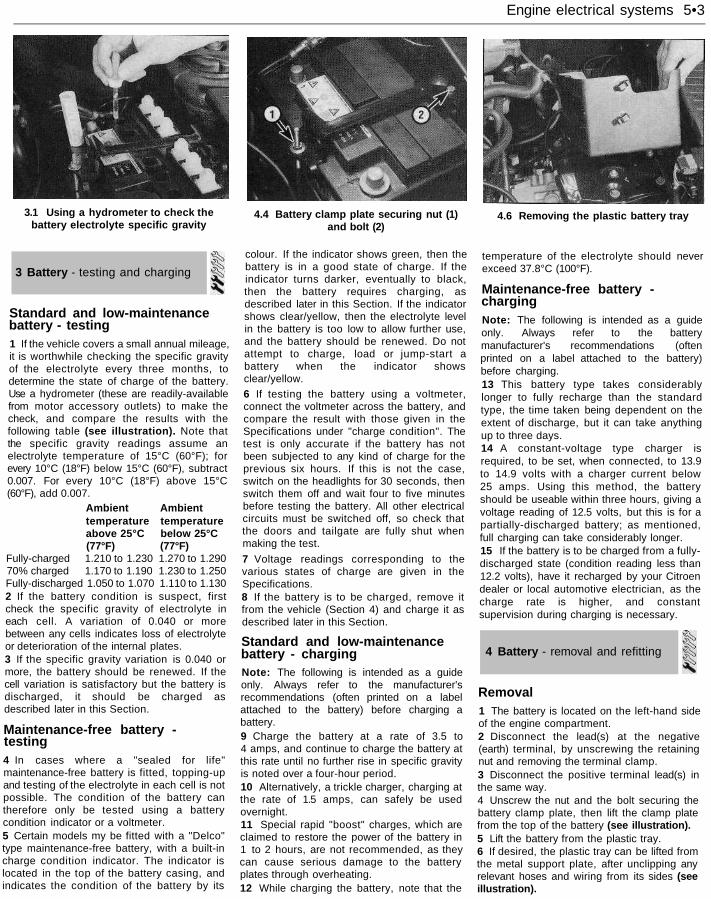
4.4 Battery clamp plate securing nut (1)and bolt (2)
colour. If the indicator shows green, then thebattery is in a good state of charge. If theindicator turns darker, eventually to black,then the battery requires charging, asdescribed later in this Section. If the indicatorshows clear/yellow, then the electrolyte levelin the battery is too low to allow further use,and the battery should be renewed. Do notattempt to charge, load or jump-start abattery when the indicator showsclear/yellow.6 If testing the battery using a voltmeter,connect the voltmeter across the battery, andcompare the result with those given in theSpecifications under "charge condition". Thetest is only accurate if the battery has notbeen subjected to any kind of charge for theprevious six hours. If this is not the case,switch on the headlights for 30 seconds, thenswitch them off and wait four to five minutesbefore testing the battery. All other electricalcircuits must be switched off, so check thatthe doors and tailgate are fully shut whenmaking the test.
7 Voltage readings corresponding to thevarious states of charge are given in theSpecifications.8 If the battery is to be charged, remove itfrom the vehicle (Section 4) and charge it asdescribed later in this Section.
Standard and low-maintenancebattery - chargingNote: The following is intended as a guideonly. Always refer to the manufacturer'srecommendations (often printed on a labelattached to the battery) before charging abattery.9 Charge the battery at a rate of 3.5 to4 amps, and continue to charge the battery atthis rate until no further rise in specific gravityis noted over a four-hour period.10 Alternatively, a trickle charger, charging atthe rate of 1.5 amps, can safely be usedovernight.11 Special rapid "boost" charges, which areclaimed to restore the power of the battery in1 to 2 hours, are not recommended, as theycan cause serious damage to the batteryplates through overheating.12 While charging the battery, note that the
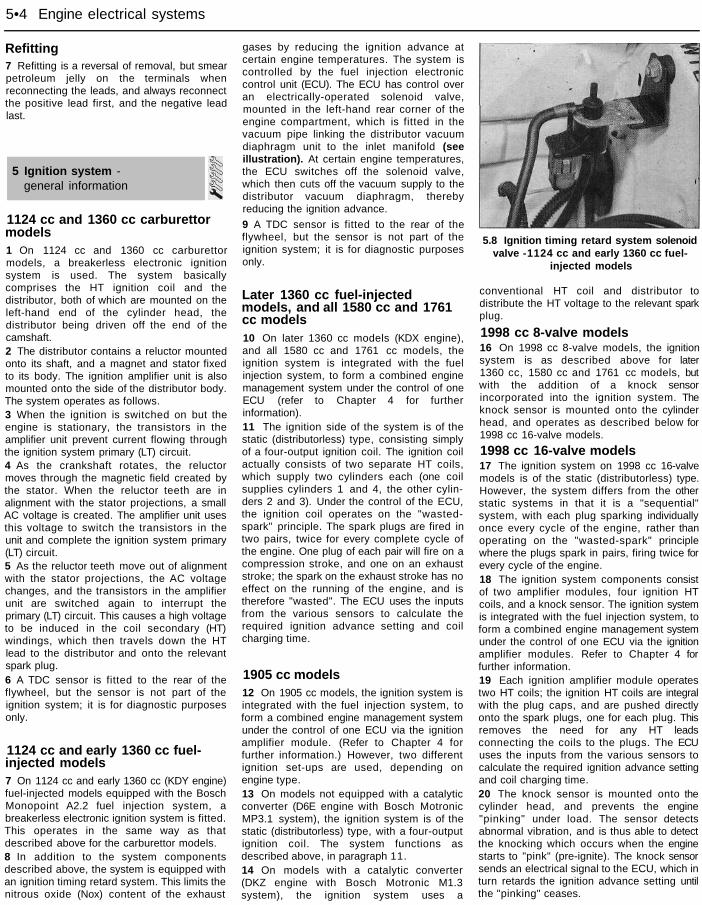
4.6 Removing the plastic battery tray
temperature of the electrolyte should neverexceed 37.8°C (100°F).
Maintenance-free battery -chargingNote: The following is intended as a guideonly. Always refer to the batterymanufacturer's recommendations (oftenprinted on a label attached to the battery)before charging.13 This battery type takes considerablylonger to fully recharge than the standardtype, the time taken being dependent on theextent of discharge, but it can take anythingup to three days.14 A constant-voltage type charger isrequired, to be set, when connected, to 13.9to 14.9 volts with a charger current below25 amps. Using this method, the batteryshould be useable within three hours, giving avoltage reading of 12.5 volts, but this is for apartially-discharged battery; as mentioned,full charging can take considerably longer.15 If the battery is to be charged from a fully-discharged state (condition reading less than12.2 volts), have it recharged by your Citroendealer or local automotive electrician, as thecharge rate is higher, and constantsupervision during charging is necessary.
4 Battery - removal and refitting
Removal1 The battery is located on the left-hand sideof the engine compartment.2 Disconnect the lead(s) at the negative(earth) terminal, by unscrewing the retainingnut and removing the terminal clamp.3 Disconnect the positive terminal lead(s) inthe same way.4 Unscrew the nut and the bolt securing thebattery clamp plate, then lift the clamp platefrom the top of the battery (see illustration).5 Lift the battery from the plastic tray.6 If desired, the plastic tray can be lifted fromthe metal support plate, after unclipping anyrelevant hoses and wiring from its sides (seeillustration).
5•4 Engine electrical systems
Refitting7 Refitting is a reversal of removal, but smearpetroleum jelly on the terminals whenreconnecting the leads, and always reconnectthe positive lead first, and the negative leadlast.
5 Ignition system -general information
1124 cc and 1360 cc carburettormodels1 On 1124 cc and 1360 cc carburettormodels, a breakerless electronic ignitionsystem is used. The system basicallycomprises the HT ignition coil and thedistributor, both of which are mounted on theleft-hand end of the cylinder head, thedistributor being driven off the end of thecamshaft.2 The distributor contains a reluctor mountedonto its shaft, and a magnet and stator fixedto its body. The ignition amplifier unit is alsomounted onto the side of the distributor body.The system operates as follows.3 When the ignition is switched on but theengine is stationary, the transistors in theamplifier unit prevent current flowing throughthe ignition system primary (LT) circuit.4 As the crankshaft rotates, the reluctormoves through the magnetic field created bythe stator. When the reluctor teeth are inalignment with the stator projections, a smallAC voltage is created. The amplifier unit usesthis voltage to switch the transistors in theunit and complete the ignition system primary(LT) circuit.5 As the reluctor teeth move out of alignmentwith the stator projections, the AC voltagechanges, and the transistors in the amplifierunit are switched again to interrupt theprimary (LT) circuit. This causes a high voltageto be induced in the coil secondary (HT)windings, which then travels down the HTlead to the distributor and onto the relevantspark plug.6 A TDC sensor is fitted to the rear of theflywheel, but the sensor is not part of theignition system; it is for diagnostic purposesonly.
1124 cc and early 1360 cc fuel-injected models7 On 1124 cc and early 1360 cc (KDY engine)fuel-injected models equipped with the BoschMonopoint A2.2 fuel injection system, abreakerless electronic ignition system is fitted.This operates in the same way as thatdescribed above for the carburettor models.8 In addition to the system componentsdescribed above, the system is equipped withan ignition timing retard system. This limits thenitrous oxide (Nox) content of the exhaust
gases by reducing the ignition advance atcertain engine temperatures. The system iscontrolled by the fuel injection electroniccontrol unit (ECU). The ECU has control overan electrically-operated solenoid valve,mounted in the left-hand rear corner of theengine compartment, which is fitted in thevacuum pipe linking the distributor vacuumdiaphragm unit to the inlet manifold (seeillustration). At certain engine temperatures,the ECU switches off the solenoid valve,which then cuts off the vacuum supply to thedistributor vacuum diaphragm, therebyreducing the ignition advance.
9 A TDC sensor is fitted to the rear of theflywheel, but the sensor is not part of theignition system; it is for diagnostic purposesonly.
Later 1360 cc fuel-injectedmodels, and all 1580 cc and 1761cc models10 On later 1360 cc models (KDX engine),and all 1580 cc and 1761 cc models, theignition system is integrated with the fuelinjection system, to form a combined enginemanagement system under the control of oneECU (refer to Chapter 4 for furtherinformation).11 The ignition side of the system is of thestatic (distributorless) type, consisting simplyof a four-output ignition coil. The ignition coilactually consists of two separate HT coils,which supply two cylinders each (one coilsupplies cylinders 1 and 4, the other cylin-ders 2 and 3). Under the control of the ECU,the ignition coil operates on the "wasted-spark" principle. The spark plugs are fired intwo pairs, twice for every complete cycle ofthe engine. One plug of each pair will fire on acompression stroke, and one on an exhauststroke; the spark on the exhaust stroke has noeffect on the running of the engine, and istherefore "wasted". The ECU uses the inputsfrom the various sensors to calculate therequired ignition advance setting and coilcharging time.
1905 cc models12 On 1905 cc models, the ignition system isintegrated with the fuel injection system, toform a combined engine management systemunder the control of one ECU via the ignitionamplifier module. (Refer to Chapter 4 forfurther information.) However, two differentignition set-ups are used, depending onengine type.13 On models not equipped with a catalyticconverter (D6E engine with Bosch MotronicMP3.1 system), the ignition system is of thestatic (distributorless) type, with a four-outputignition coil. The system functions asdescribed above, in paragraph 11.14 On models with a catalytic converter(DKZ engine with Bosch Motronic M1.3system), the ignition system uses a
5.8 Ignition timing retard system solenoidvalve -1124 cc and early 1360 cc fuel-
injected models
conventional HT coil and distributor todistribute the HT voltage to the relevant sparkplug.
1998 cc 8-valve models16 On 1998 cc 8-valve models, the ignitionsystem is as described above for later1360 cc, 1580 cc and 1761 cc models, butwith the addition of a knock sensorincorporated into the ignition system. Theknock sensor is mounted onto the cylinderhead, and operates as described below for1998 cc 16-valve models.
1998 cc 16-valve models17 The ignition system on 1998 cc 16-valvemodels is of the static (distributorless) type.However, the system differs from the otherstatic systems in that it is a "sequential"system, with each plug sparking individuallyonce every cycle of the engine, rather thanoperating on the "wasted-spark" principlewhere the plugs spark in pairs, firing twice forevery cycle of the engine.18 The ignition system components consistof two amplifier modules, four ignition HTcoils, and a knock sensor. The ignition systemis integrated with the fuel injection system, toform a combined engine management systemunder the control of one ECU via the ignitionamplifier modules. Refer to Chapter 4 forfurther information.19 Each ignition amplifier module operatestwo HT coils; the ignition HT coils are integralwith the plug caps, and are pushed directlyonto the spark plugs, one for each plug. Thisremoves the need for any HT leadsconnecting the coils to the plugs. The ECUuses the inputs from the various sensors tocalculate the required ignition advance settingand coil charging time.20 The knock sensor is mounted onto thecylinder head, and prevents the engine"pinking" under load. The sensor detectsabnormal vibration, and is thus able to detectthe knocking which occurs when the enginestarts to "pink" (pre-ignite). The knock sensorsends an electrical signal to the ECU, which inturn retards the ignition advance setting untilthe "pinking" ceases.
Engine electrical systems 5•5
6 Ignition system - testing
Ignition systems with a distributorNote: Refer to the precautions given inSection 1 of this Chapter before starting work.Always switch off the ignition beforedisconnecting or connecting any component,and when using a multi-meter to checkresistances.
General1 The components of electronic ignitionsystems are normally very reliable; most faultsare far more likely to be due to loose or dirtyconnections, or to "tracking" of HT voltagedue to dirt, dampness or damaged insulation,than to the failure of any of the system'scomponents. Always check all wiringthoroughly before condemning an electricalcomponent, and work methodically toeliminate all other possibilities before decidingthat a particular component is faulty.
2 The old practice of checking for a spark byholding the live end of an HT lead a shortdistance away from the engine is notrecommended; not only is there a high risk ofa powerful electric shock, but the HT coil oramplifier unit will be damaged. Similarly, nevertry to "diagnose" misfires by pulling off oneHT lead at a time.
Engine will not start3 If the engine either will not turn at all, or onlyturns very slowly, check the battery andstarter motor. Connect a voltmeter across thebattery terminals (meter positive probe tobattery positive terminal), disconnect theignition coil HT lead from the distributor capand earth it, then note the voltage readingobtained while turning the engine on thestarter for (no more than) ten seconds. If thereading obtained is less than approximately9.5 volts, first check the battery, starter motorand charging system as described in therelevant Sections of this Chapter.
4 If the engine turns at normal speed but willnot start, check the HT circuit by connecting atiming light (following the equipmentmanufacturer's instructions) and turning theengine on the starter motor. If the lightflashes, voltage is reaching the spark plugs,so these should be checked first. If the lightdoes not flash, check the HT leadsthemselves, followed by the distributor cap,carbon brush and rotor arm, using theinformation given in Chapter 1.5 If there is a spark, check the fuel system forfaults, referring to the relevant Part of Chapter4 for further information.6 If there is still no spark, check the voltage atthe ignition HT coil "+" terminal; it should bethe same as the battery voltage (ie, at least
11.7 volts). If the voltage at the coil is lessthan battery voltage by 1 volt or more, checkthe feed back through the fusebox andignition switch to the battery and its earth,until the fault is found.7 If the feed to the HT coil is sound, check thecoil's primary and secondary windingresistance as described later in this Section.Renew the coil if faulty, but be check carefullythe condition of the LT connectionsthemselves before doing so, to ensure thatthe fault is not due to dirty or poorly-fastenedconnectors.8 If the HT coil is in good condition, the faultis probably within the amplifier unit ordistributor stator assembly (1124 cc and1360 cc models) or the engine managementECU (1905 cc models). Testing of thesecomponents should be entrusted to a Citroendealer.
Engine misfires9 An irregular misfire suggests either a looseconnection or intermittent fault on the primarycircuit, or an HT fault on the coil side of therotor arm.10 With the ignition switched off, checkcarefully through the system, ensuring that allconnections are clean and securely fastened.If the equipment is available, check the LTcircuit as described above.11 Check that the HT coil, the distributor capand the HT leads are clean and dry. Check theleads themselves and the spark plugs (bysubstitution, if necessary), then check thedistributor cap, carbon brush and rotor arm asdescribed in Chapter 1.12 Regular misfiring is almost certainly due toa fault in the distributor cap, HT leads or sparkplugs. Use a timing light (paragraph 4 above)to check whether HT voltage is present at allleads.13 If HT voltage is not present on anyparticular lead, the fault will be in that lead, orin the distributor cap. If HT is present on allleads, the fault will be in the spark plugs;check and renew them if there is any doubtabout their condition.14 If no HT voltage is present, check the HTcoil; its secondary windings may be breakingdown under load.
Static (distributorless) ignitionsystems15 If a fault appears in the enginemanagement (fuel injection/ignition) system,first ensure that the fault is not due to a poorelectrical connection, or to poor maintenance;ie, check that the air cleaner filter element isclean, that the spark plugs are in goodcondition and correctly gapped, and that theengine breather hoses are clear andundamaged. Refer to Chapter 1 for furtherinformation. Also check that the acceleratorcable is correctly adjusted, as described inChapter 4. If the engine is running very
roughly, check the compression pressures asdescribed in Chapter 2, and the valveclearances (1360 cc models only) asdescribed in Chapter 1.16 If these checks fail to reveal the cause ofthe problem, the vehicle should be taken to asuitably-equipped Citroen dealer for testing. Awiring block connector is incorporated in theengine management circuit, into which aspecial electronic diagnostic tester can beplugged. The tester will locate the fault quicklyand simply, alleviating the need to test all thesystem components individually, which is atime-consuming operation that carries a highrisk of damaging the ECU.17 The only ignition system checks whichcan be carried out by the home mechanic arethose described in Chapter 1 relating to thespark plugs, and also the ignition coil testdescribed in this Chapter. If necessary, thesystem wiring and wiring connectors can bechecked as described in Chapter 12, ensuringthat the ECU wiring connector(s) have firstbeen disconnected.
7 Ignition HT coil(s) -removal, testing and refitting
Removal
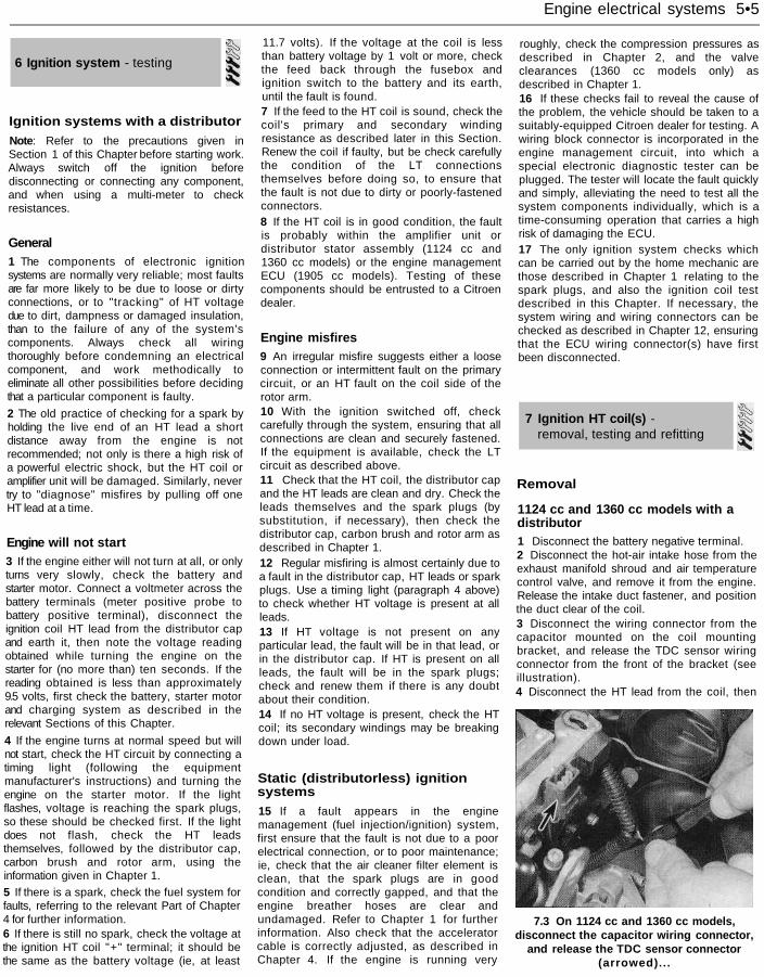
1124 cc and 1360 cc models with adistributor1 Disconnect the battery negative terminal.2 Disconnect the hot-air intake hose from theexhaust manifold shroud and air temperaturecontrol valve, and remove it from the engine.Release the intake duct fastener, and positionthe duct clear of the coil.3 Disconnect the wiring connector from thecapacitor mounted on the coil mountingbracket, and release the TDC sensor wiringconnector from the front of the bracket (seeillustration).4 Disconnect the HT lead from the coil, then
7.3 On 1124 cc and 1360 cc models,disconnect the capacitor wiring connector,
and release the TDC sensor connector(arrowed)...
5•6 Engine electrical systems
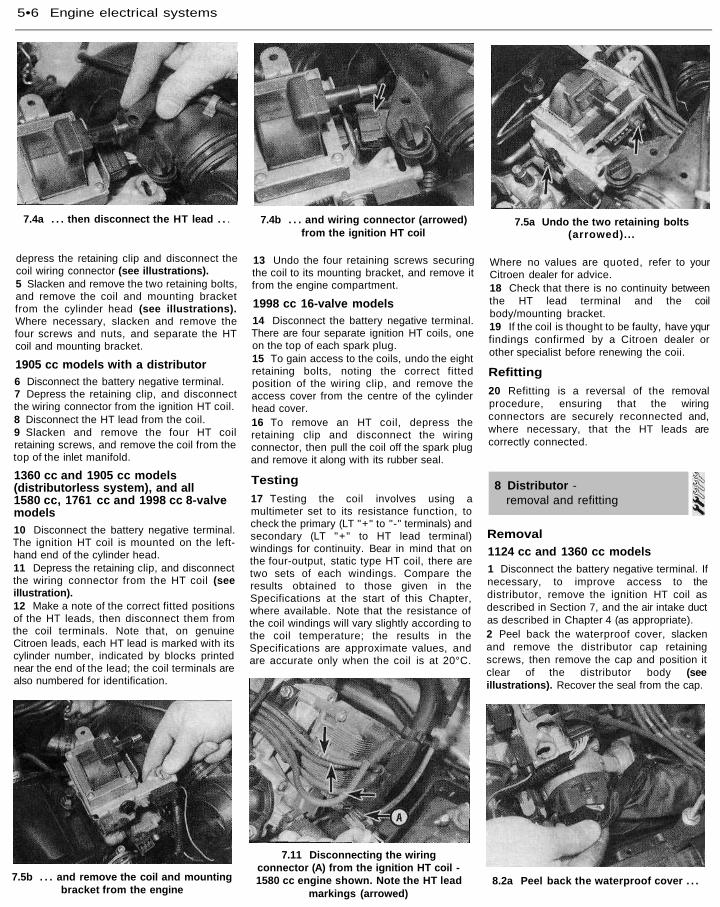
7.4a . . . then disconnect the HT lead . . .
depress the retaining clip and disconnect thecoil wiring connector (see illustrations).5 Slacken and remove the two retaining bolts,and remove the coil and mounting bracketfrom the cylinder head (see illustrations).Where necessary, slacken and remove thefour screws and nuts, and separate the HTcoil and mounting bracket.
1905 cc models with a distributor6 Disconnect the battery negative terminal.7 Depress the retaining clip, and disconnectthe wiring connector from the ignition HT coil.8 Disconnect the HT lead from the coil.9 Slacken and remove the four HT coilretaining screws, and remove the coil from thetop of the inlet manifold.
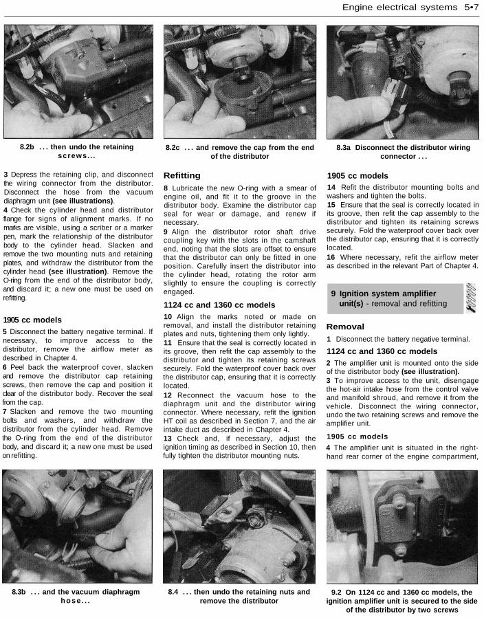
1360 cc and 1905 cc models(distributorless system), and all1580 cc, 1761 cc and 1998 cc 8-valvemodels10 Disconnect the battery negative terminal.The ignition HT coil is mounted on the left-hand end of the cylinder head.11 Depress the retaining clip, and disconnectthe wiring connector from the HT coil (seeillustration).12 Make a note of the correct fitted positionsof the HT leads, then disconnect them fromthe coil terminals. Note that, on genuineCitroen leads, each HT lead is marked with itscylinder number, indicated by blocks printednear the end of the lead; the coil terminals arealso numbered for identification.
7.4b . . . and wiring connector (arrowed)from the ignition HT coil
13 Undo the four retaining screws securingthe coil to its mounting bracket, and remove itfrom the engine compartment.
1998 cc 16-valve models14 Disconnect the battery negative terminal.There are four separate ignition HT coils, oneon the top of each spark plug.15 To gain access to the coils, undo the eightretaining bolts, noting the correct fittedposition of the wiring clip, and remove theaccess cover from the centre of the cylinderhead cover.16 To remove an HT coil, depress theretaining clip and disconnect the wiringconnector, then pull the coil off the spark plugand remove it along with its rubber seal.
Testing
17 Testing the coil involves using amultimeter set to its resistance function, tocheck the primary (LT "+" to "-" terminals) andsecondary (LT "+" to HT lead terminal)windings for continuity. Bear in mind that onthe four-output, static type HT coil, there aretwo sets of each windings. Compare theresults obtained to those given in theSpecifications at the start of this Chapter,where available. Note that the resistance ofthe coil windings will vary slightly according tothe coil temperature; the results in theSpecifications are approximate values, andare accurate only when the coil is at 20°C.
7.5a Undo the two retaining bolts(arrowed)...
Where no values are quoted, refer to yourCitroen dealer for advice.18 Check that there is no continuity betweenthe HT lead terminal and the coilbody/mounting bracket.19 If the coil is thought to be faulty, have yqurfindings confirmed by a Citroen dealer orother specialist before renewing the coii.
Refitting
20 Refitting is a reversal of the removalprocedure, ensuring that the wiringconnectors are securely reconnected and,where necessary, that the HT leads arecorrectly connected.
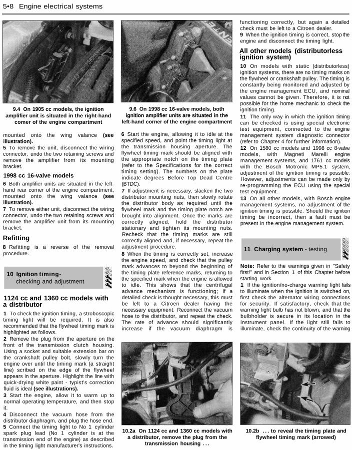
Removal1124 cc and 1360 cc models1 Disconnect the battery negative terminal. Ifnecessary, to improve access to thedistributor, remove the ignition HT coil asdescribed in Section 7, and the air intake ductas described in Chapter 4 (as appropriate).2 Peel back the waterproof cover, slackenand remove the distributor cap retainingscrews, then remove the cap and position itclear of the distributor body (seeillustrations). Recover the seal from the cap.
7.5b . . . and remove the coil and mountingbracket from the engine
7.11 Disconnecting the wiringconnector (A) from the ignition HT coil -1580 cc engine shown. Note the HT lead
markings (arrowed)8.2a Peel back the waterproof cover . . .
8 Distributor -removal and refitting
Engine electrical systems 5•7
8.2b . . . then undo the retainingscrews. . .
8.2c . . . and remove the cap from the end 8.3a Disconnect the distributor wiringof the distributor connector . . .
3 Depress the retaining clip, and disconnectthe wiring connector from the distributor.Disconnect the hose from the vacuumdiaphragm unit (see illustrations).4 Check the cylinder head and distributorflange for signs of alignment marks. If nomarks are visible, using a scriber or a markerpen, mark the relationship of the distributorbody to the cylinder head. Slacken andremove the two mounting nuts and retainingplates, and withdraw the distributor from thecylinder head (see illustration). Remove theO-ring from the end of the distributor body,and discard it; a new one must be used onrefitting.
1905 cc models5 Disconnect the battery negative terminal. Ifnecessary, to improve access to thedistributor, remove the airflow meter asdescribed in Chapter 4.6 Peel back the waterproof cover, slackenand remove the distributor cap retainingscrews, then remove the cap and position itclear of the distributor body. Recover the sealfrom the cap.7 Slacken and remove the two mountingbolts and washers, and withdraw thedistributor from the cylinder head. Removethe O-ring from the end of the distributorbody, and discard it; a new one must be usedon refitting.
Refitting
8 Lubricate the new O-ring with a smear ofengine oil, and fit it to the groove in thedistributor body. Examine the distributor capseal for wear or damage, and renew ifnecessary.9 Align the distributor rotor shaft drivecoupling key with the slots in the camshaftend, noting that the slots are offset to ensurethat the distributor can only be fitted in oneposition. Carefully insert the distributor intothe cylinder head, rotating the rotor armslightly to ensure the coupling is correctlyengaged.
1124 cc and 1360 cc models10 Align the marks noted or made onremoval, and install the distributor retainingplates and nuts, tightening them only lightly.11 Ensure that the seal is correctly located inits groove, then refit the cap assembly to thedistributor and tighten its retaining screwssecurely. Fold the waterproof cover back overthe distributor cap, ensuring that it is correctlylocated.12 Reconnect the vacuum hose to thediaphragm unit and the distributor wiringconnector. Where necessary, refit the ignitionHT coil as described in Section 7, and the airintake duct as described in Chapter 4.13 Check and, if necessary, adjust theignition timing as described in Section 10, thenfully tighten the distributor mounting nuts.
1905 cc models14 Refit the distributor mounting bolts andwashers and tighten the bolts.15 Ensure that the seal is correctly located inits groove, then refit the cap assembly to thedistributor and tighten its retaining screwssecurely. Fold the waterproof cover back overthe distributor cap, ensuring that it is correctlylocated.16 Where necessary, refit the airflow meteras described in the relevant Part of Chapter 4.
Removal1 Disconnect the battery negative terminal.
1124 cc and 1360 cc models2 The amplifier unit is mounted onto the sideof the distributor body (see illustration).3 To improve access to the unit, disengagethe hot-air intake hose from the control valveand manifold shroud, and remove it from thevehicle. Disconnect the wiring connector,undo the two retaining screws and remove theamplifier unit.
1905 cc models
4 The amplifier unit is situated in the right-hand rear corner of the engine compartment,
8.3b . . . and the vacuum diaphragmhose . . .
8.4 . . . then undo the retaining nuts andremove the distributor
9.2 On 1124 cc and 1360 cc models, theignition amplifier unit is secured to the side
of the distributor by two screws
9 Ignition system amplifierunit(s) - removal and refitting
5•8 Engine electrical systems
9.4 On 1905 cc models, the ignitionamplifier unit is situated in the right-hand
comer of the engine compartment
mounted onto the wing valance (seeillustration).5 To remove the unit, disconnect the wiringconnector, undo the two retaining screws andremove the amplifier from its mountingbracket.
1998 cc 16-valve models6 Both amplifier units are situated in the left-hand rear corner of the engine compartment,mounted onto the wing valance (seeillustration).7 To remove either unit, disconnect the wiringconnector, undo the two retaining screws andremove the amplifier unit from its mountingbracket.
Refitting8 Refitting is a reverse of the removalprocedure.
10 Ignition timing-checking and adjustment
1124 cc and 1360 cc models witha distributor1 To check the ignition timing, a stroboscopictiming light will be required. It is alsorecommended that the flywheel timing mark ishighlighted as follows.2 Remove the plug from the aperture on thefront of the transmission clutch housing.Using a socket and suitable extension bar onthe crankshaft pulley bolt, slowly turn theengine over until the timing mark (a straightline) scribed on the edge of the flywheelappears in the aperture. Highlight the line withquick-drying white paint - typist's correctionfluid is ideal (see illustrations).3 Start the engine, allow it to warm up tonormal operating temperature, and then stopit.4 Disconnect the vacuum hose from thedistributor diaphragm, and plug the hose end.5 Connect the timing light to No 1 cylinderspark plug lead (No 1 cylinder is at thetransmission end of the engine) as describedin the timing light manufacturer's instructions.
9.6 On 1998 cc 16-valve models, bothignition amplifier units are situated in the
left-hand corner of the engine compartment
6 Start the engine, allowing it to idle at thespecified speed, and point the timing light atthe transmission housing aperture. Theflywheel timing mark should be aligned withthe appropriate notch on the timing plate(refer to the Specifications for the correcttiming setting). The numbers on the plateindicate degrees Before Top Dead Centre(BTDC).7 If adjustment is necessary, slacken the twodistributor mounting nuts, then slowly rotatethe distributor body as required until theflywheel mark and the timing plate notch arebrought into alignment. Once the marks arecorrectly aligned, hold the distributorstationary and tighten its mounting nuts.Recheck that the timing marks are stillcorrectly aligned and, if necessary, repeat theadjustment procedure.8 When the timing is correctly set, increasethe engine speed, and check that the pulleymark advances to beyond the beginning ofthe timing plate reference marks, returning tothe specified mark when the engine is allowedto idle. This shows that the centrifugaladvance mechanism is functioning; if adetailed check is thought necessary, this mustbe left to a Citroen dealer having thenecessary equipment. Reconnect the vacuumhose to the distributor, and repeat the check.The rate of advance should significantlyincrease if the vacuum diaphragm is
functioning correctly, but again a detailedcheck must be left to a Citroen dealer.9 When the ignition timing is correct, stop theengine and disconnect the timing light.
All other models (distributorlessignition system)10 On models with static (distributorless)ignition systems, there are no timing marks onthe flywheel or crankshaft pulley. The timing isconstantly being monitored and adjusted bythe engine management ECU, and nominalvalues cannot be given. Therefore, it is notpossible for the home mechanic to check theignition timing.11 The only way in which the ignition timingcan be checked is using special electronictest equipment, connected to the enginemanagement system diagnostic connector(refer to Chapter 4 for further information).12 On 1580 cc models and 1998 cc 8-valvemodels, with Magneti Marelli enginemanagement systems, and 1761 cc modelswith the Bosch Motronic MP5.1 system,adjustment of the ignition timing is possible.However, adjustments can be made only byre-programming the ECU using the specialtest equipment.13 On all other models, with Bosch enginemanagement systems, no adjustment of theignition timing is possible. Should the ignitiontiming be incorrect, then a fault must bepresent in the engine management system.
Note: Refer to the warnings given in "Safetyfirst!" and in Section 1 of this Chapter beforestarting work.1 If the ignition/no-charge warning light failsto illuminate when the ignition is switched on,first check the alternator wiring connectionsfor security. If satisfactory, check that thewarning light bulb has not blown, and that thebulbholder is secure in its location in theinstrument panel. If the light still fails toilluminate, check the continuity of the warning
10.2a On 1124 cc and 1360 cc models witha distributor, remove the plug from the
transmission housing . . .
10.2b . . . to reveal the timing plate andflywheel timing mark (arrowed)
11 Charging system - testing
Engine electrical systems 5•9
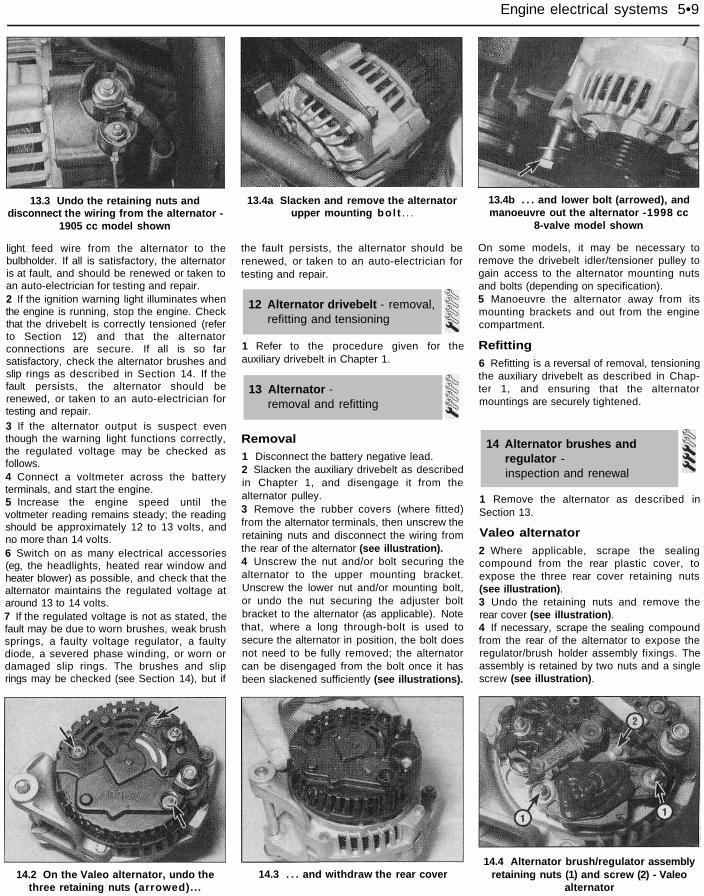
13.3 Undo the retaining nuts anddisconnect the wiring from the alternator -
1905 cc model shown
light feed wire from the alternator to thebulbholder. If all is satisfactory, the alternatoris at fault, and should be renewed or taken toan auto-electrician for testing and repair.2 If the ignition warning light illuminates whenthe engine is running, stop the engine. Checkthat the drivebelt is correctly tensioned (referto Section 12) and that the alternatorconnections are secure. If all is so farsatisfactory, check the alternator brushes andslip rings as described in Section 14. If thefault persists, the alternator should berenewed, or taken to an auto-electrician fortesting and repair.3 If the alternator output is suspect eventhough the warning light functions correctly,the regulated voltage may be checked asfollows.4 Connect a voltmeter across the batteryterminals, and start the engine.5 Increase the engine speed until thevoltmeter reading remains steady; the readingshould be approximately 12 to 13 volts, andno more than 14 volts.6 Switch on as many electrical accessories(eg, the headlights, heated rear window andheater blower) as possible, and check that thealternator maintains the regulated voltage ataround 13 to 14 volts.7 If the regulated voltage is not as stated, thefault may be due to worn brushes, weak brushsprings, a faulty voltage regulator, a faultydiode, a severed phase winding, or worn ordamaged slip rings. The brushes and sliprings may be checked (see Section 14), but if
13.4a Slacken and remove the alternatorupper mounting bol t . . .
the fault persists, the alternator should berenewed, or taken to an auto-electrician fortesting and repair.
Removal1 Disconnect the battery negative lead.2 Slacken the auxiliary drivebelt as describedin Chapter 1, and disengage it from thealternator pulley.3 Remove the rubber covers (where fitted)from the alternator terminals, then unscrew theretaining nuts and disconnect the wiring fromthe rear of the alternator (see illustration).4 Unscrew the nut and/or bolt securing thealternator to the upper mounting bracket.Unscrew the lower nut and/or mounting bolt,or undo the nut securing the adjuster boltbracket to the alternator (as applicable). Notethat, where a long through-bolt is used tosecure the alternator in position, the bolt doesnot need to be fully removed; the alternatorcan be disengaged from the bolt once it hasbeen slackened sufficiently (see illustrations).
13.4b . . . and lower bolt (arrowed), andmanoeuvre out the alternator -1998 cc
8-valve model shown
On some models, it may be necessary toremove the drivebelt idler/tensioner pulley togain access to the alternator mounting nutsand bolts (depending on specification).5 Manoeuvre the alternator away from itsmounting brackets and out from the enginecompartment.
Refitting6 Refitting is a reversal of removal, tensioningthe auxiliary drivebelt as described in Chap-ter 1, and ensuring that the alternatormountings are securely tightened.
14 Alternator brushes andregulator -inspection and renewal
1 Remove the alternator as described inSection 13.
Valeo alternator2 Where applicable, scrape the sealingcompound from the rear plastic cover, toexpose the three rear cover retaining nuts(see illustration).3 Undo the retaining nuts and remove therear cover (see illustration).4 If necessary, scrape the sealing compoundfrom the rear of the alternator to expose theregulator/brush holder assembly fixings. Theassembly is retained by two nuts and a singlescrew (see illustration).
14.2 On the Valeo alternator, undo thethree retaining nuts (arrowed)...
14.3 . . . and withdraw the rear cover14.4 Alternator brush/regulator assembly
retaining nuts (1) and screw (2) - Valeoalternator
12 Alternator drivebelt - removal,refitting and tensioning
13 Alternator -removal and refitting
1 Refer to the procedure given for theauxiliary drivebelt in Chapter 1.

5•10 Engine electrical systems
14.5 Removing the cover from thearmature shaft - Valeo alternator
5 Pull the plastic cover from the rear of thearmature shaft (see illustration).6 Undo the retaining nuts and screw, andwithdraw the regulator/brush holder assemblyfrom the rear of the alternator (seeillustration).7 Measure the protrusion of each brush fromthe its holder. No minimum dimension isspecified by the manufacturers, but excessivewear should be self-evident. If either brushrequires renewal, the completeregulator/brush holder assembly must berenewed. It is not possible to renew thebrushes separately.8 If the brushes are still serviceable, cleanthem with a petrol-moistened cloth. Checkthat the brush spring tension is equal for bothbrushes, and provides a reasonable pressure.The brushes must move freely in their holders.9 Clean the alternator slip-rings with a petrol-moistened cloth (see illustration). Check forsigns of scoring, burning or severe pitting onthe surface of the slip-rings. It may bepossible to have the slip rings renovated byan electrical specialist.10 Refit the regulator/brush holder assemblyusing a reverse of the removal procedure.11 Refit the alternator as described inSection 13.
Bosch alternator12 Unclip the cover from the rear of thealternator.13 If necessary, scrape the sealingcompound from the rear of the alternator, toexpose the regulator/brush holder assemblyretaining screws. Slacken and remove the tworetaining screws, and remove theregulator/brush holder from the rear of thealternator.14 Examine the alternator components asdescribed above in paragraphs 7 to 9.15 Refit the regulator/brush holder assembly,and securely tighten its retaining screws.16 Clip the rear cover onto the alternator,and refit the alternator as described in Sec-tion 13.
Mitsubishi alternator17 At the time of writing, no information onthe Mitsubishi alternator was available.
14.6 Removing the brush/regulatorassembly - Valeo alternator
Although the components differ in detail, thesame basic principles outlined previously forthe Valeo alternator are applicable.
Note: Refer to the precautions given in"Safety first!" and in Section 1 of this Chapterbefore starting work.1 If the starter motor fails to operate when theignition key is turned to the appropriateposition, the following possible causes maybe to blame.(a) The battery is faulty.(b) The electrical connections between the
switch, solenoid, battery and startermotor are somewhere failing to pass thenecessary current from the batterythrough the starter to earth.
(c) The solenoid is faulty.(d) The starter motor is mechanically or
electrically defective.2 To check the battery, switch on theheadlights. If they dim after a few seconds,this indicates that the battery is discharged -recharge (see Section 3) or renew the battery.If the headlights glow brightly, operate theignition switch and observe the lights. If theydim, then this indicates that current isreaching the starter motor - therefore, the faultmust lie in the starter motor. If the lightscontinue to glow brightly (and no clickingsound can be heard from the starter motorsolenoid), this indicates that there is a fault inthe circuit or solenoid - refer to the followingparagraphs. If the starter motor turns slowlywhen operated, but the battery is in goodcondition, then this indicates that either thestarter motor is faulty, or there is considerableresistance somewhere in the circuit.3 If a fault in the circuit is suspected,disconnect the battery leads (including theearth connection to the body), thestarter/solenoid wiring, and the engine/transmission earth strap. Thoroughly cleanthe connections, reconnect the leads andwiring, then use a voltmeter or test light tocheck that full battery voltage is available atthe battery positive lead connection to the
14.9 Ensure the alternator slip-rings(arrowed) are clean and undamaged
solenoid, and that the earth is sound. Smearpetroleum jelly around the battery terminals toprevent corrosion - corroded connections areamong the most frequent causes of electricalsystem faults.4 If the battery and all connections,'are ingood condition, check the circuit bydisconnecting the wire from the solenoidblade terminal. Connect a voltmeter or testlight between the wire end and a good earth(such as the battery negative terminal), andcheck that the wire is live when the ignitionswitch is turned to the "start" position. If it is,then the circuit is sound - if not, the circuitwiring can be checked as described inChapter 12, Section 2.5 The solenoid contacts can be checked byconnecting a voltmeter or test light betweenthe battery positive feed connection on thestarter side of the solenoid, and earth. Whenthe ignition switch is turned to the "start"position, there should be a reading or lightedbulb, as applicable. If there is no reading orlighted bulb, the solenoid is faulty, and shouldbe renewed.6 If the circuit and solenoid are provedsound, the fault must lie in the starter motor.Begin checking the starter motor by removingit (see Section 16), and checking the brushes(see Section 17). If the fault does not lie in thebrushes, the motor windings must be faulty. Inthis event, it may be possible to have thestarter motor overhauled by a specialist, butcheck on the availability and cost of sparesbefore proceeding, as it may prove moreeconomical to obtain a new or exchangemotor.
Removal1 Disconnect the battery negative lead.2 On 1124 cc, 1360 cc models and 1998 cc16-valve models, to improve access to themotor, remove the air cleaner housing andmounting bracket, as described in Chapter 4.3 On all models, so that access to the motorcan be gained both from above and below,
15 Starting system - testing
16 Starter motor -removal and refitting

Engine electrical systems 5•11
16.4 Unscrew the two retaining nuts(arrowed) and disconnect the wiring from
the rear of the starter motor - 1905 ccmodel shown
firmly apply the handbrake, then jack up thefront of the vehicle and support it on axlestands.4 Slacken and remove the two retaining nuts,and disconnect the wiring from the rear of thestarter motor (see illustration). Recover thewashers under the nuts.5 Working at the rear of the starter motor,undo the three mounting bolts, supporting themotor as the bolts are withdrawn. Recover thewashers from under the bolt heads, and notethe locations of any wiring or hose bracketssecured by the bolts (see illustration). Notethat on 1580 cc and larger-engined models,the top retaining bolt may foul the clutchrelease mechanism as it is withdrawn, butthere is no need to withdraw it completely toremove the starter motor.
17.3a . . . then prise off the C-clip . . .
16.5 Unscrew the starter motor securingbolts (1). Note the location of the
bracket (2) - 1905 cc model shown
6 Manoeuvre the starter motor out fromunderneath the engine.
Refitting7 Refitting is a reversal of removal, ensuringthat any wiring or hose brackets are in placeunder the bolt heads, as noted prior toremoval.
Valeo starter motor1 No minimum brush length is specified bythe manufacturers, but it should be self-evident if the brushes are worn to the extent
17.2 On the Valeo starter motor, removethe plastic cap from the end of the starter
motor armature shaft . . .
where renewal is required. With the motorremoved as described in Section 16, proceedas follows.2 Carefully prise the plastic cap from the endof the armature shaft, using a screwdriver orsimilar tool (see illustration).3 Prise the C-clip from the end of thearmature shaft, and recover the shim (seeillustrations).4 Unscrew the two through-bolts, thenwithdraw the end cover from the motorcasing, and recover the shim from thearmature shaft (see illustrations). Do not mixup the shim with the one removed in theprevious paragraph.5 Carefully pull the brush plate from the endof the armature (see illustration).6 Using a suitable screwdriver, release the
17.4a Remove the through-bolts . . .
17.4b . . . then withdraw the end cover,and recover the shim (arrowed)
17.5 Carefully pull the brush plate from the 17.6a . . . then, using a screwdriver . . .end of the armature . . .
17.3b . . . and recover the shim
17 Starter motor - brush renewal
5•12 Engine electrical systems
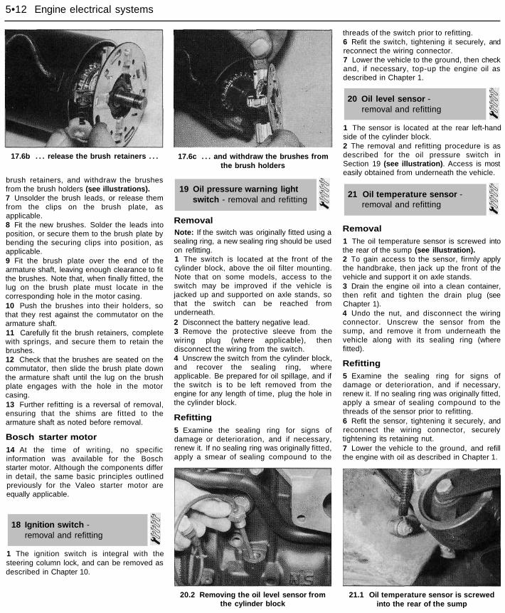
17.6b . . . release the brush retainers . . .
brush retainers, and withdraw the brushesfrom the brush holders (see illustrations).7 Unsolder the brush leads, or release themfrom the clips on the brush plate, asapplicable.8 Fit the new brushes. Solder the leads intoposition, or secure them to the brush plate bybending the securing clips into position, asapplicable.9 Fit the brush plate over the end of thearmature shaft, leaving enough clearance to fitthe brushes. Note that, when finally fitted, thelug on the brush plate must locate in thecorresponding hole in the motor casing.10 Push the brushes into their holders, sothat they rest against the commutator on thearmature shaft.11 Carefully fit the brush retainers, completewith springs, and secure them to retain thebrushes.12 Check that the brushes are seated on thecommutator, then slide the brush plate downthe armature shaft until the lug on the brushplate engages with the hole in the motorcasing.13 Further refitting is a reversal of removal,ensuring that the shims are fitted to thearmature shaft as noted before removal.
Bosch starter motor14 At the time of writing, no specificinformation was available for the Boschstarter motor. Although the components differin detail, the same basic principles outlinedpreviously for the Valeo starter motor areequally applicable.
18 Ignition switch -removal and refitting
1 The ignition switch is integral with thesteering column lock, and can be removed asdescribed in Chapter 10.
17.6c . . . and withdraw the brushes fromthe brush holders
RemovalNote: If the switch was originally fitted using asealing ring, a new sealing ring should be usedon refitting.1 The switch is located at the front of thecylinder block, above the oil filter mounting.Note that on some models, access to theswitch may be improved if the vehicle isjacked up and supported on axle stands, sothat the switch can be reached fromunderneath.2 Disconnect the battery negative lead.3 Remove the protective sleeve from thewiring plug (where applicable), thendisconnect the wiring from the switch.4 Unscrew the switch from the cylinder block,and recover the sealing ring, whereapplicable. Be prepared for oil spillage, and ifthe switch is to be left removed from theengine for any length of time, plug the hole inthe cylinder block.
Refitting5 Examine the sealing ring for signs ofdamage or deterioration, and if necessary,renew it. If no sealing ring was originally fitted,apply a smear of sealing compound to the
threads of the switch prior to refitting.6 Refit the switch, tightening it securely, andreconnect the wiring connector.7 Lower the vehicle to the ground, then checkand, if necessary, top-up the engine oil asdescribed in Chapter 1.
20 Oil level sensor -removal and refitting
1 The sensor is located at the rear left-handside of the cylinder block.2 The removal and refitting procedure is asdescribed for the oil pressure switch inSection 19 (see illustration). Access is mosteasily obtained from underneath the vehicle.
Removal1 The oil temperature sensor is screwed intothe rear of the sump (see illustration).2 To gain access to the sensor, firmly applythe handbrake, then jack up the front of thevehicle and support it on axle stands.3 Drain the engine oil into a clean container,then refit and tighten the drain plug (seeChapter 1).4 Undo the nut, and disconnect the wiringconnector. Unscrew the sensor from thesump, and remove it from underneath thevehicle along with its sealing ring (wherefitted).
Refitting5 Examine the sealing ring for signs ofdamage or deterioration, and if necessary,renew it. If no sealing ring was originally fitted,apply a smear of sealing compound to thethreads of the sensor prior to refitting.6 Refit the sensor, tightening it securely, andreconnect the wiring connector, securelytightening its retaining nut.7 Lower the vehicle to the ground, and refillthe engine with oil as described in Chapter 1.
20.2 Removing the oil level sensor fromthe cylinder block
21.1 Oil temperature sensor is screwedinto the rear of the sump
19 Oil pressure warning lightswitch - removal and refitting
21 Oil temperature sensor -removal and refitting