chapter 5 function of output controller and application
TRANSCRIPT
CHAPTER 5
FUNCTION OF OUTPUT CONTROLLER AND
APPLICATION
TIMERS
• Many applications in industrial control systems need timer functions.
• Timer is used to activate or de-activate a device after a preset time interval.
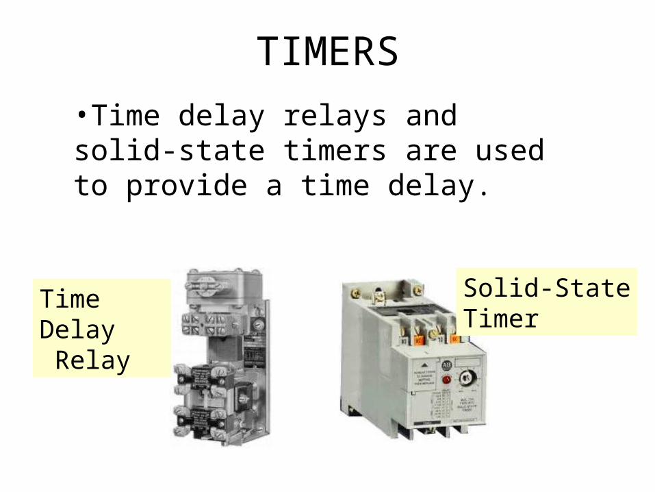
•Time delay relays and solid-state timers are used to provide a time delay.
Time Delay Relay
Solid-StateTimer
TIMERS

QUANTITIES IN TIMER INSTRUCTION
Preset Time •Represents the time duration of the timing circuit.• e.g. if a time delay of 10 s is required, the timer will have a preset of 10 s.
Accumulated Time •Represents the amount of time that has elapsed since it is energized.

Time Base • Timers can typically be programmed with
several different time bases: 1 s, 0.1 s, and 0.01 s are typical time bases.
• E.g. if you enter 0.1 for the time base and 50 for the preset time the timer would have a 5 s delay (50 x 0.1 s = 5 s).

Generic Block-Formatted Timer Instruction
Timers are most often represented by boxes in a ladder logic.
Preset timeTime baseAccumulated time
Retentive timer block
Control line controls the actual timing operation of the timer.Whenever this line is true the timer will time.
Reset line resets the the timer's accumulated value to zero.
Output line
The timer continuously compares its accumulated time with its preset time. Its output is logic 0 as long as the accumulated time is less than the preset time. When the two become equal the output changes to logic 1.
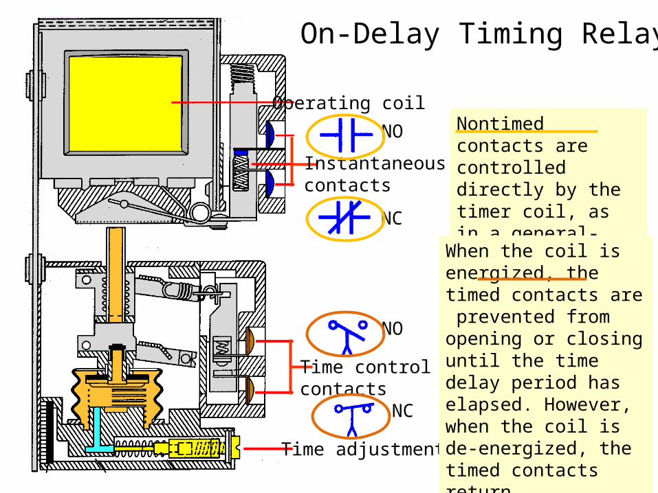
On-Delay Timing Relay
Operating coil
Instantaneous contacts
NO
NC
Nontimed contacts are controlled directly by the timer coil, as in a general-purpose control relay.
Time control contacts
NO
NC
Time adjustment
When the coil is energized, the timed contacts are prevented from opening or closing until the time delay period has elapsed. However, when the coil is de-energized, the timed contacts return instantaneously to their normal state.
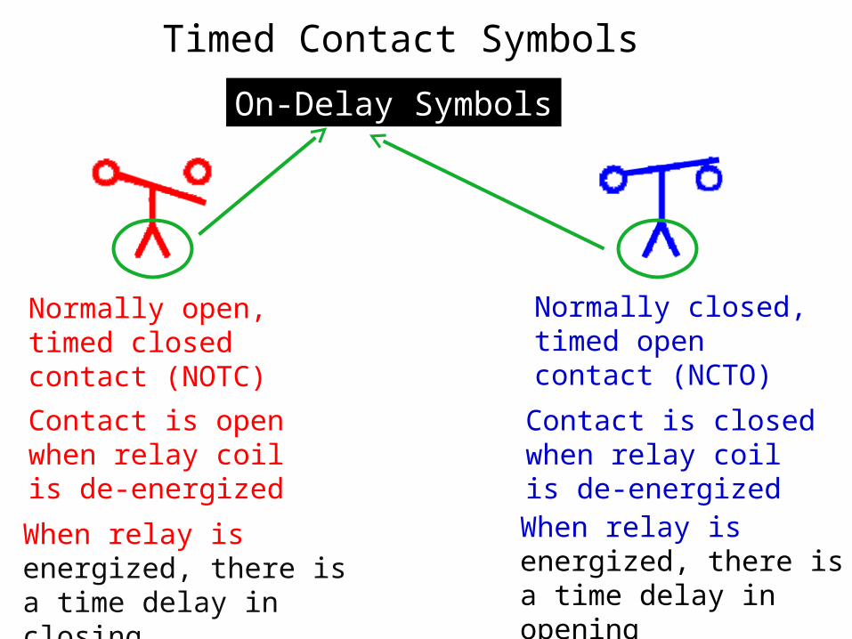
Normally open, timed closed contact (NOTC)
Contact is open when relay coil is de-energized
When relay is energized, there is a time delay in closing
Timed Contact Symbols
On-Delay Symbols
Normally closed, timed open contact (NCTO)
Contact is closed when relay coil is de-energized
When relay is energized, there is a time delay in opening
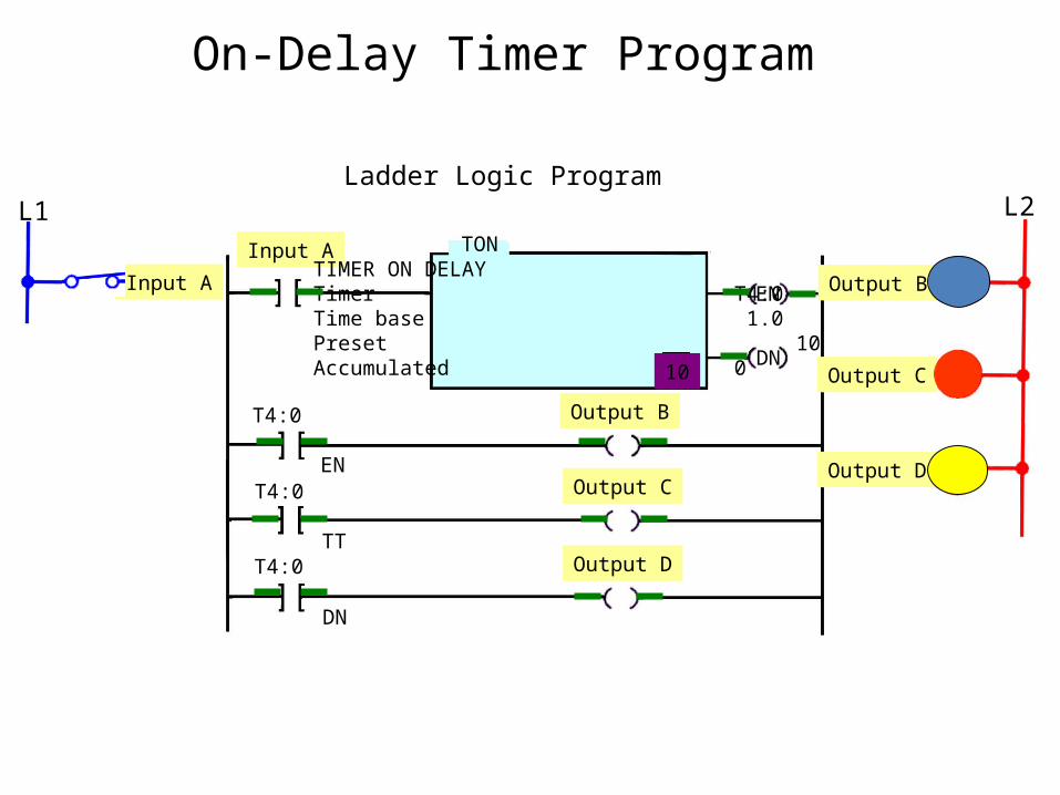
On-Delay Timer Program
Ladder Logic ProgramL1 L2
Input A
Input A
T4:0
T4:0
T4:0
EN
TT
DN
TONTIMER ON DELAYTimer T4:0Time base 1.0Preset 10Accumulated 0
EN
DN
Output B
Output B
Output C
Output COutput D
Output D
G
R
Y
10

On-Delay Relay Timer Circuit (NOTC Contact)
L1 L2S1
L1
Sequence of operation
10 s
S1 open, TD de-energized,TD1 open, L1 is off.
After 10 s, TD1 closes, L1 is switched on.
S1 closes, TD energizes,timing period starts,TD1 still open, L1 is still off.
S1 is opened, TD de-energizes, TD1 opens instantly, L1 is switched off.
10 s
OFFON
Input
Output
Timing Diagram
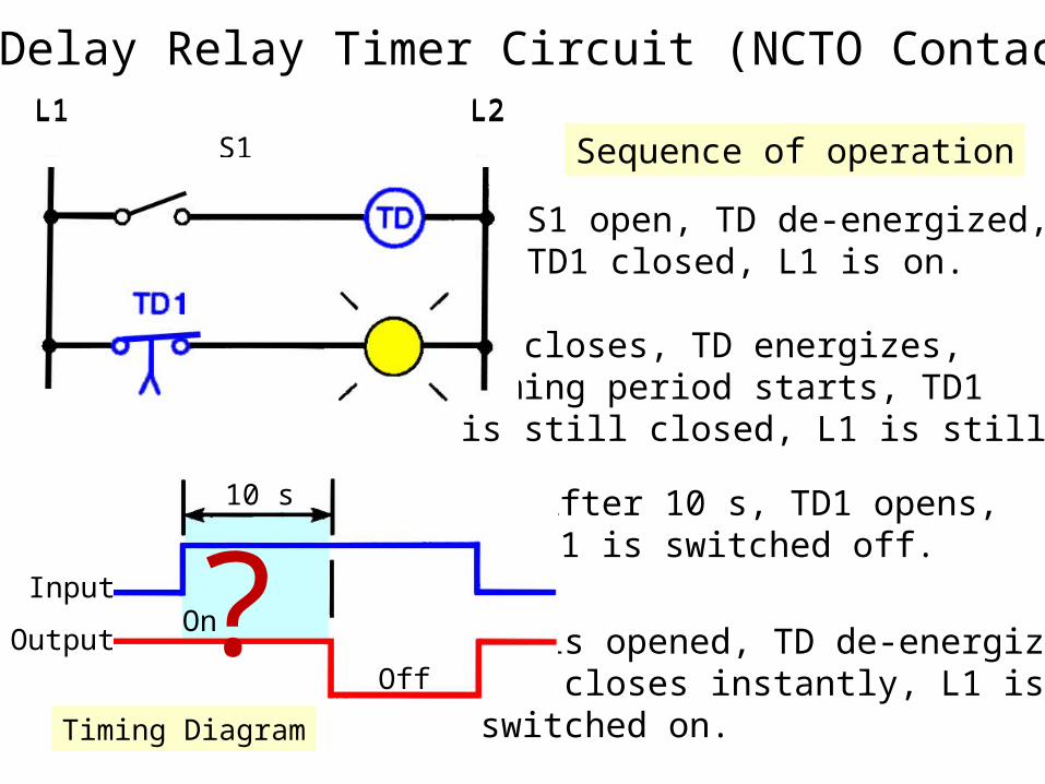
On-Delay Relay Timer Circuit (NCTO Contact)
S1 open, TD de-energized,TD1 closed, L1 is on.
Sequence of operationL1 L2
L1
S1
10 s
After 10 s, TD1 opens,L1 is switched off.
S1 closes, TD energizes,timing period starts, TD1is still closed, L1 is still on.
L1 L2
S1 is opened, TD de-energizes,TD1 closes instantly, L1 isswitched on.
10 s
On
Off
Input
Output
Timing Diagram
?

Normally open, timed open contacts (NOTO).
Contact is normallyopen when relay coilis de-energized.
When relay coil is energized, contact closes instantly.When relay coil is de-energized, there is a time delay before the contact opens.
Timed Contact Symbols
Off Delay Symbols
Normally closed, timed closed contacts (NCTC).
Contact is normallyclosed when relay coilis de-energized.
When relay coil is energized, contact opens instantly.
When relay coil is de-energized, there is a time delay before the contact closes.
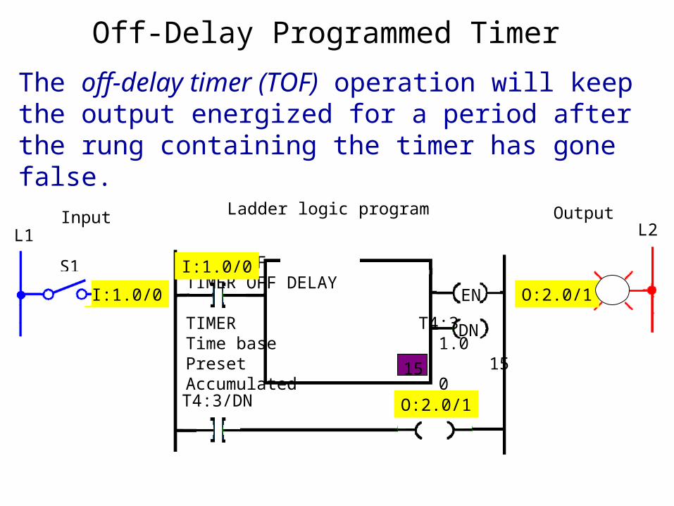
Off-Delay Programmed Timer
The off-delay timer (TOF) operation will keep the output energized for a period after the rung containing the timer has gone false.
EN
DN
TOFTIMER OFF DELAY
TIMER T4:3Time base 1.0Preset 15Accumulated 0
I:1.0/0
I:1.0/0
O:2.0/1
O:2.0/1T4:3/DN
PL
L1 L2Input OutputLadder logic program
S1
15
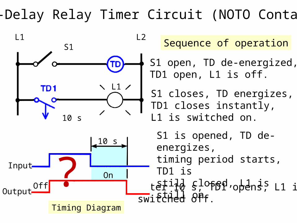
Off-Delay Relay Timer Circuit (NOTO Contact)
L1 L2S1
L1
Sequence of operation
S1 open, TD de-energized,TD1 open, L1 is off.
S1 closes, TD energizes,TD1 closes instantly, L1 is switched on.
S1 is opened, TD de-energizes,timing period starts, TD1 isstill closed, L1 is still on.
10 s
After 10 s, TD1 opens, L1 isswitched off.
10 s
Input
OutputOff
On
Timing Diagram
?
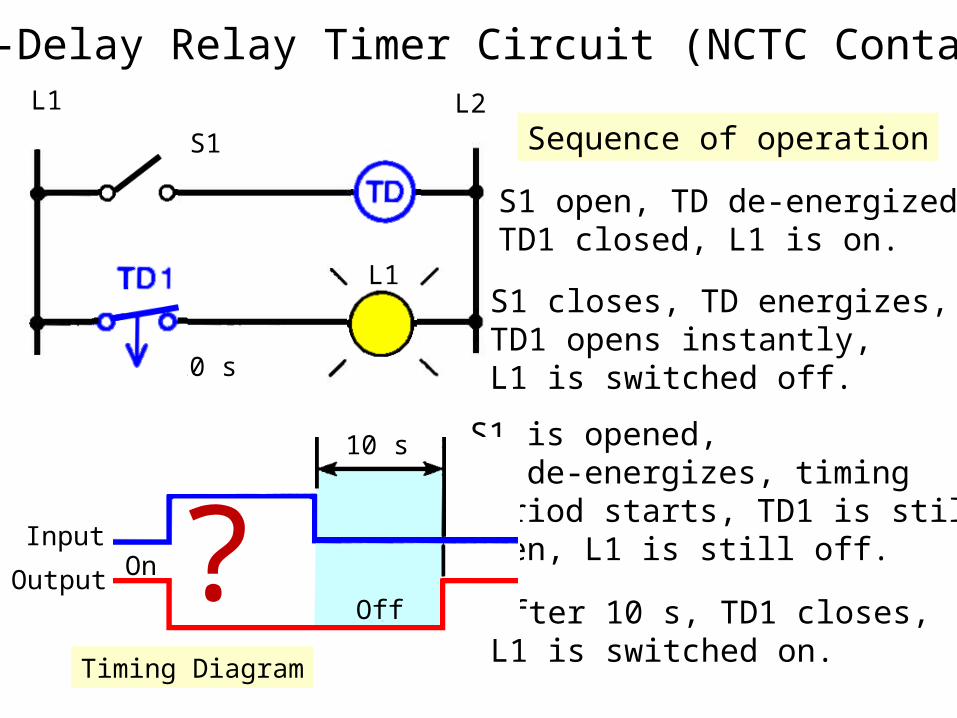
Off-Delay Relay Timer Circuit (NCTC Contact)L1 L2
S1
L1
Sequence of operation
S1 open, TD de-energized,TD1 closed, L1 is on.
S1 closes, TD energizes,TD1 opens instantly, L1 is switched off.
S1 is opened, TD de-energizes, timingperiod starts, TD1 is stillopen, L1 is still off.
10 s
After 10 s, TD1 closes,L1 is switched on.
10 s
Input
Output On
Off
Timing Diagram
?

NONRETENTIVE TIMER
• Is also known as TMR• Has only 1 input• Timer enabled if the input
logic is ON• Timer reset if the input logic
is OFF• Non-retentive - loss of power
flow to the timer causes the timer instruction to reset.
TMR TIMER0
T0
K40
INPUT
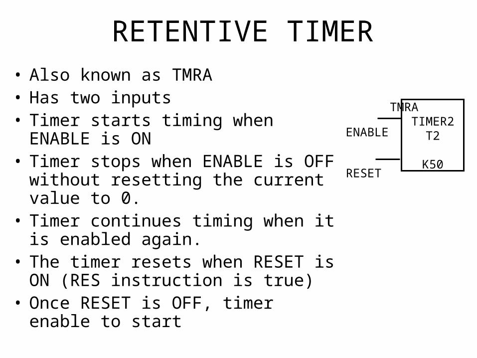
RETENTIVE TIMER• Also known as TMRA• Has two inputs• Timer starts timing when
ENABLE is ON• Timer stops when ENABLE is OFF
without resetting the current value to 0.
• Timer continues timing when it is enabled again.
• The timer resets when RESET is ON (RES instruction is true)
• Once RESET is OFF, timer enable to start
TMRA TIMER2
T2
K50
ENABLE
RESET

Retentive Timer
A retentive timer accumulates time whenever the device receives power, and maintains the current time should power be removed from the device. Once the device accumulates time equal to its preset value, the contacts of the device change state. The retentive timer must be intentionally reset with a separate signal for the accumulated time to be reset.
Electromechnical Retentive Timer
Cam operatedcontact
Motor-drivencam
Once power is applied, the motor starts turning the cam. The positioning of the lobes determines the time it takes to activate the contacts. If power is removed from the motor, the shaft stops but does not reset.

EXERCISE

CASE 1• Using a timer, a toggle switch and a buzzer. Write a ladder diagram
so that the buzzer will ON immediately, but OFF after 5 sec the input is OFF. Choose the type of timer necessary and assume the preset value for the timer is 0.1 sec.
TMR TIMER0
T0K50
INPUTX0
T0Y1=buzzer
Off Delay Timer (NOTO contact) is used
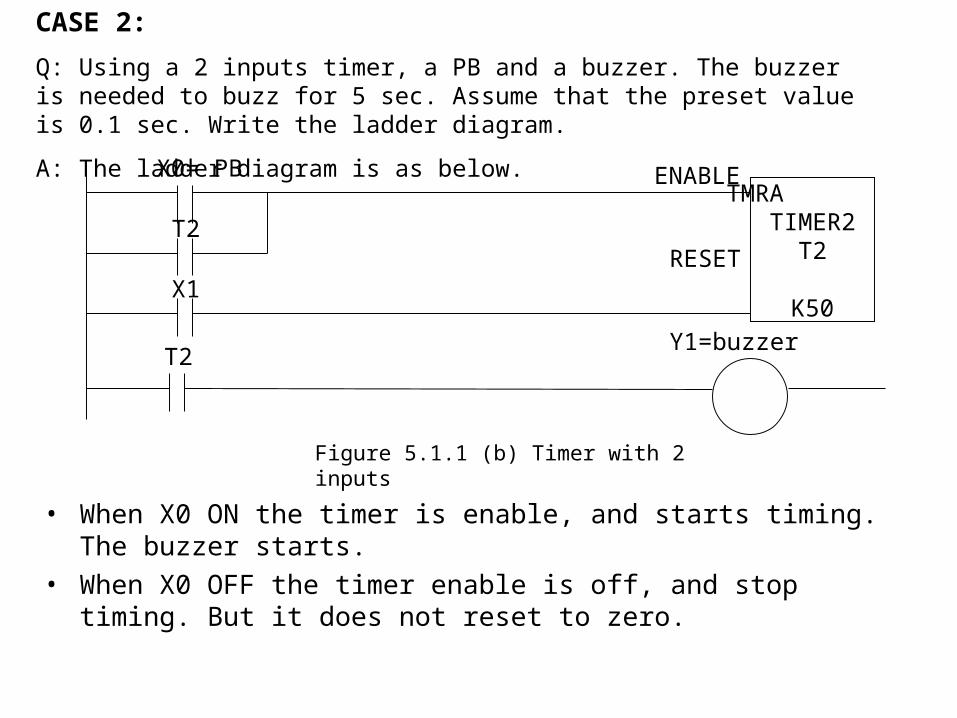
• When X0 ON the timer is enable, and starts timing. The buzzer starts.• When X0 OFF the timer enable is off, and stop timing. But it does not
reset to zero.
TMRA TIMER2
T2
K50
ENABLE
RESET
T2Y1=buzzer
X0= PB
Figure 5.1.1 (b) Timer with 2 inputs
CASE 2:
Q: Using a 2 inputs timer, a PB and a buzzer. The buzzer is needed to buzz for 5 sec. Assume that the preset value is 0.1 sec. Write the ladder diagram.
A: The ladder diagram is as below.
T2
X1
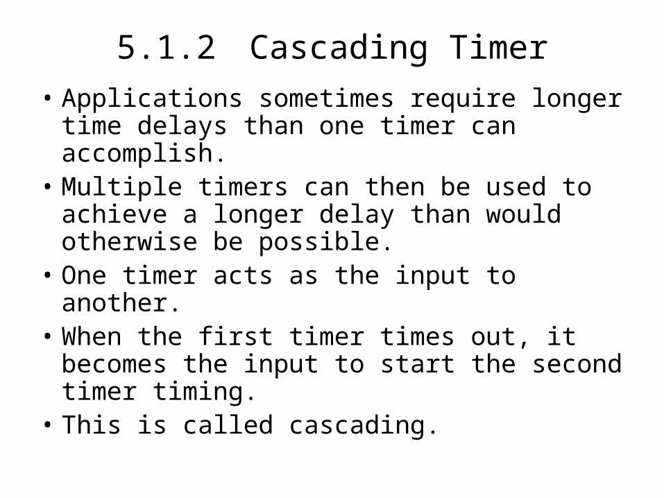
5.1.2 Cascading Timer• Applications sometimes require longer time
delays than one timer can accomplish.• Multiple timers can then be used to achieve a
longer delay than would otherwise be possible.
• One timer acts as the input to another.• When the first timer times out, it becomes the
input to start the second timer timing.• This is called cascading.

When X0 is ON, timer will start timing. After 99 sec, Timer 1will trigger T0 to open. Then T0 will initiate Timer 1, and timing
for another 51 seconds.Usually used when requirements demand more time than is
available from a single timer. Therefore, two or more timers can be programmed together to get the desire time.
TMRT0
K99
X0
T0TMRT1
K51Figure 5.1.2 (a) Cascading Timer
CASE 3:
Q: One maximum timer can be set for 99sec. Let say preset value is 1 sec. Time needed to set is 150. In this case cascading timer is used.

CASCADING

CASCADING TIMER
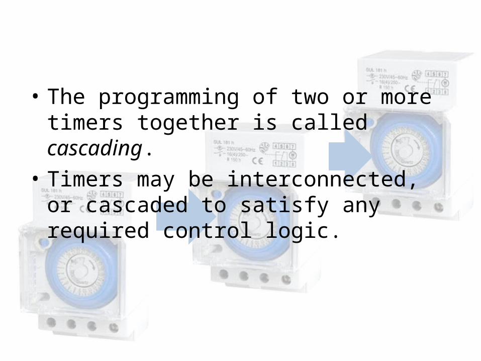
• The programming of two or more timers together is called cascading.
• Timers may be interconnected, or cascaded to satisfy any required control logic.
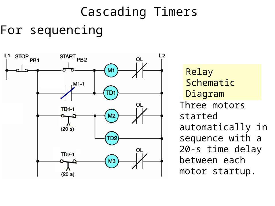
Cascading Timers
Three motors started automatically in sequence with a 20-s time delay between each motor startup.
Relay Schematic Diagram
For sequencing
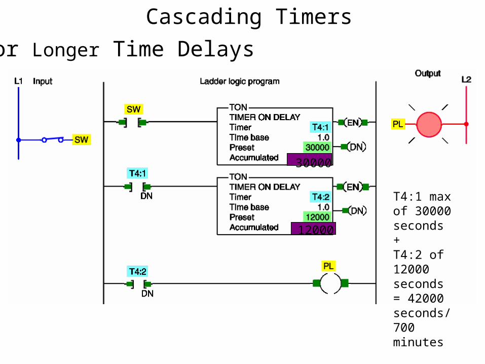
Cascading Timers
30000
12000
For Longer Time Delays
T4:1 max of 30000 seconds+T4:2 of 12000 seconds= 42000 seconds/700 minutes
COUNTER
• Electronic counters can count up, count down, or be combined to count up and down.
• They are dependent on external sources, such as parts traveling past a sensor or actuating a limit switch for counting.
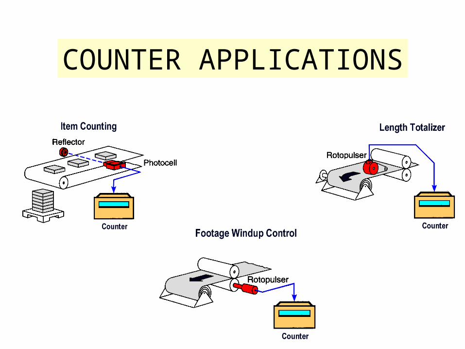
COUNTER APPLICATIONS
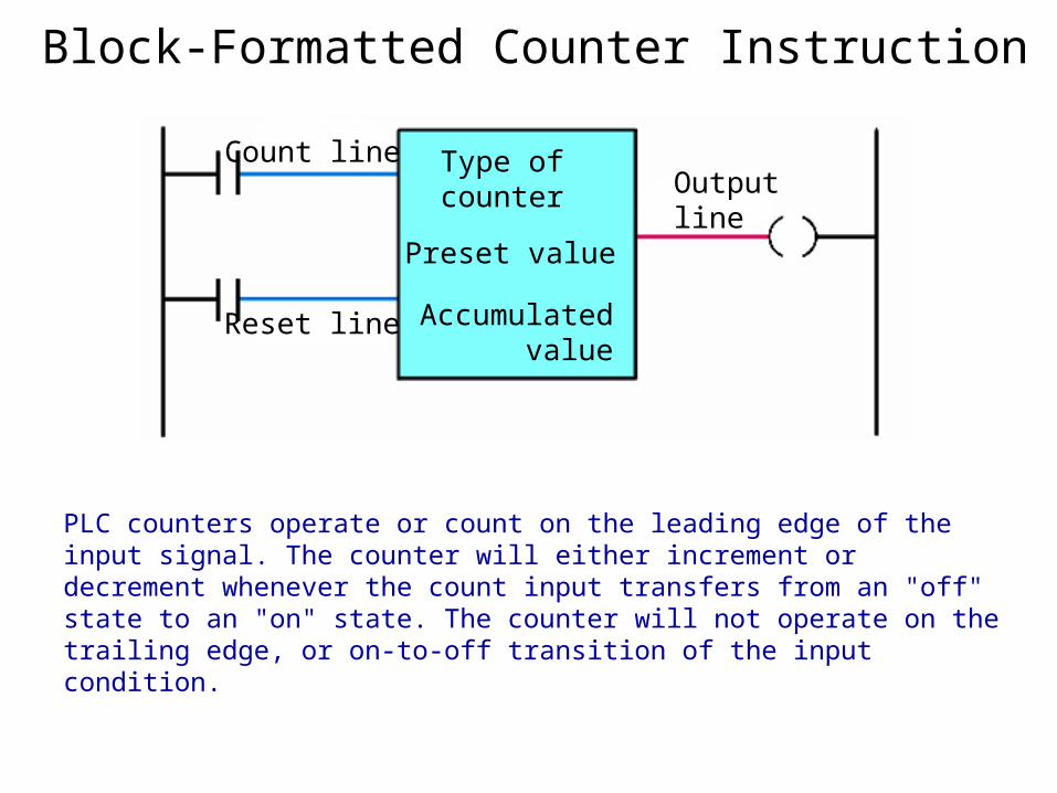
Block-Formatted Counter Instruction
Type of counter
Preset value
Accumulated value
Count line
Reset line
Outputline
PLC counters operate or count on the leading edge of the input signal. The counter will either increment or decrement whenever the count input transfers from an "off" state to an "on" state. The counter will not operate on the trailing edge, or on-to-off transition of the input condition.

Counter Counting Sequence
PLC counters are normally retentive. Whatever count was contained in the counter at the time of a processor shutdown will be restored to the counter on power-up. The counter may be reset, however, if the reset condition is activated at the time of power restoration.
PLC counters can be designed to count up to a preset value or to count down to a preset value.
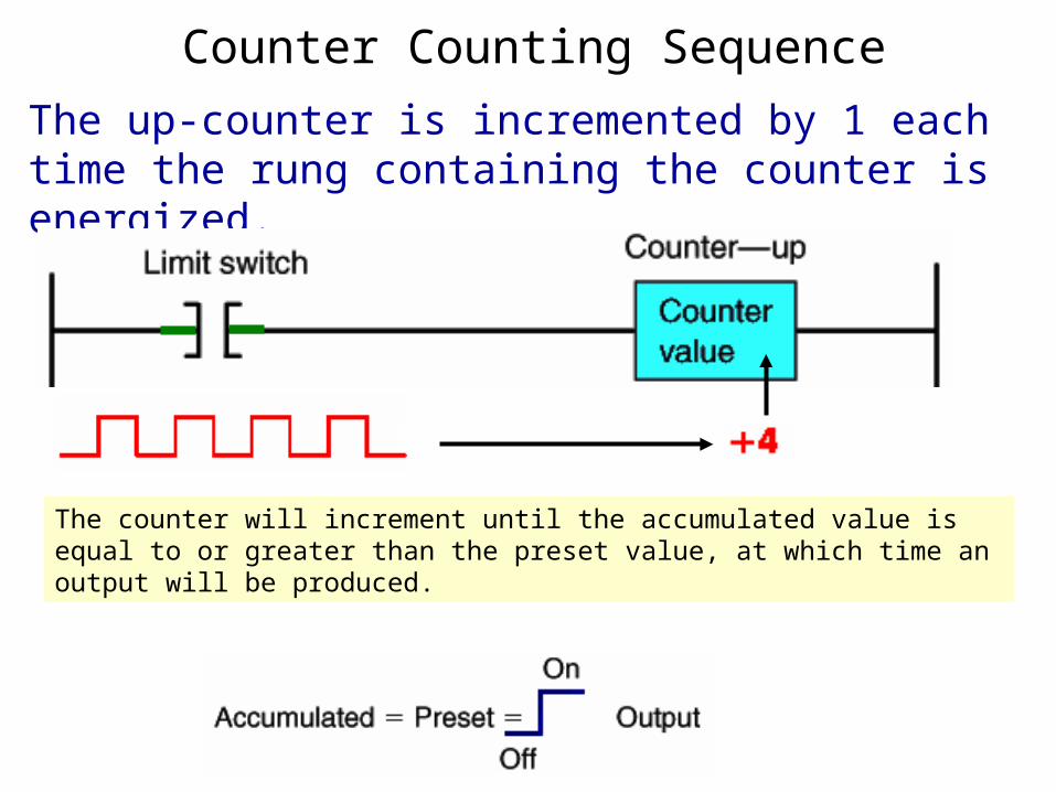
The up-counter is incremented by 1 each time the rung containing the counter is energized.
Counter Counting Sequence
The counter will increment until the accumulated value is equal to or greater than the preset value, at which time an output will be produced.
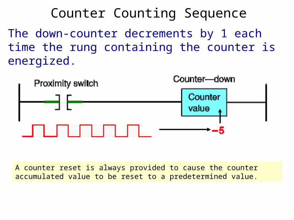
The down-counter decrements by 1 each time the rung containing the counter is energized.
Counter Counting Sequence
A counter reset is always provided to cause the counter accumulated value to be reset to a predetermined value.

UP- COUNTER
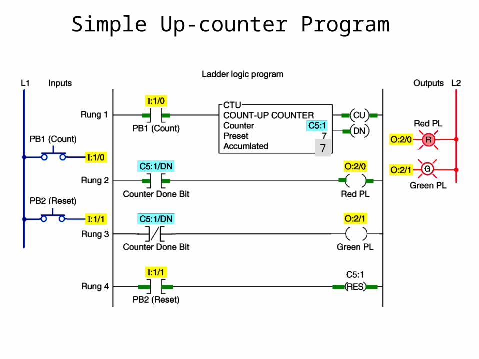
Simple Up-counter Program
7

Up-counter Program Timing Diagram
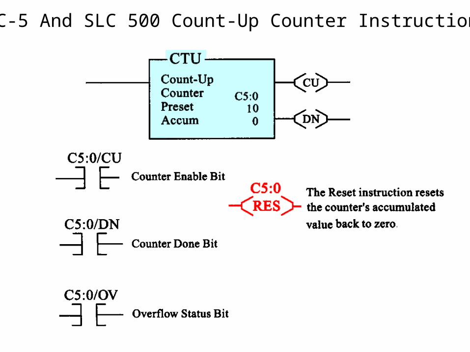
PLC-5 And SLC 500 Count-Up Counter Instruction
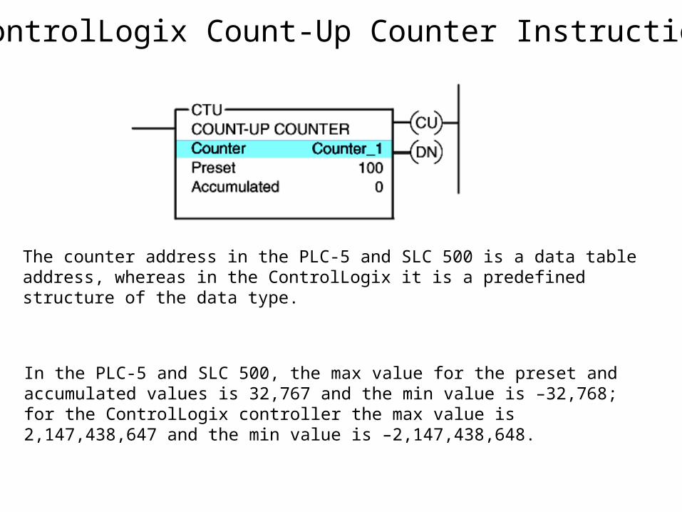
ControlLogix Count-Up Counter Instruction
The counter address in the PLC-5 and SLC 500 is a data table address, whereas in the ControlLogix it is a predefined structure of the data type.
In the PLC-5 and SLC 500, the max value for the preset and accumulated values is 32,767 and the min value is –32,768; for the ControlLogix controller the max value is 2,147,438,647 and the min value is –2,147,438,648.
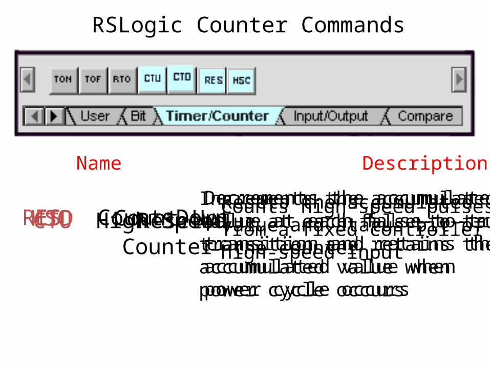
RSLogic Counter Commands
Command Name Description
CTU Count-UpIncrements the accumulatedvalue at each false-to-truetransition and retains theaccumulated value whenpower cycle occurs
CTD Count-DownDecrements the accumulatedvalue at each false-to-truetransition and retains theaccumulated value whenpower cycle occurs
HSC High-Speed Counter
Counts high-speed pulsesfrom a fixed controllerhigh-speed input
RES ResetResets the accumulatedvalue and status bit of the counter
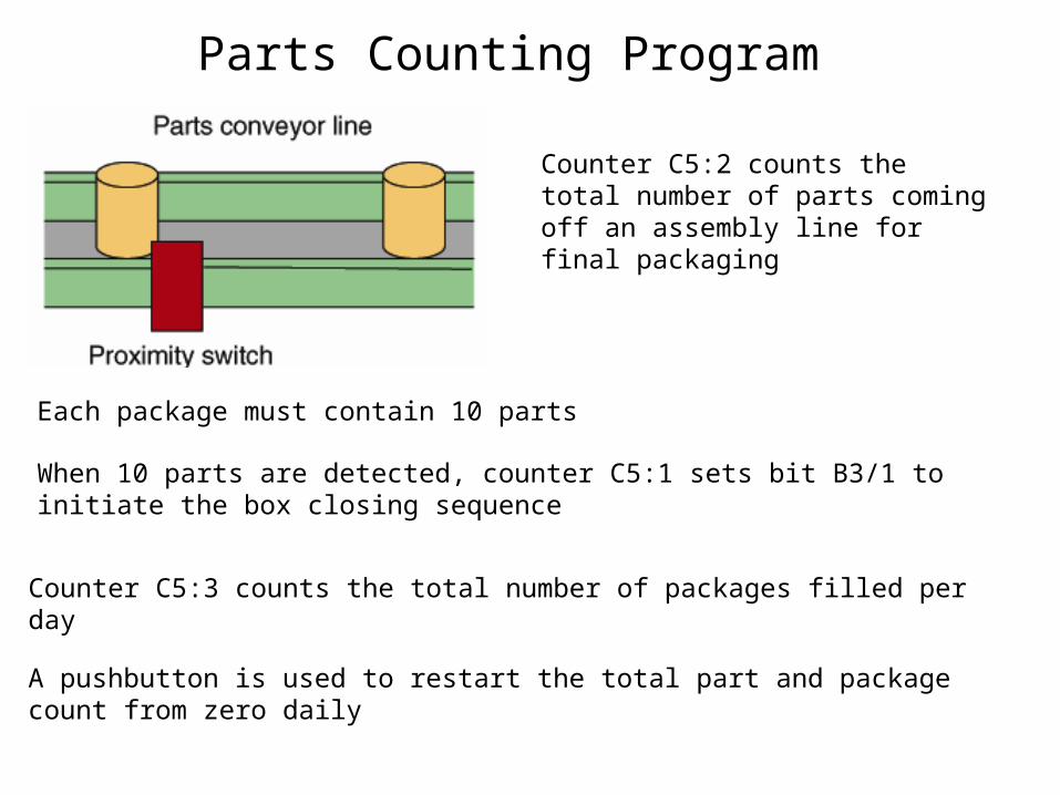
Parts Counting Program
Counter C5:2 counts the total number of parts coming off an assembly line for final packaging
Each package must contain 10 parts
When 10 parts are detected, counter C5:1 sets bit B3/1 to initiate the box closing sequence
Counter C5:3 counts the total number of packages filled per day
A pushbutton is used to restart the total part and package count from zero daily
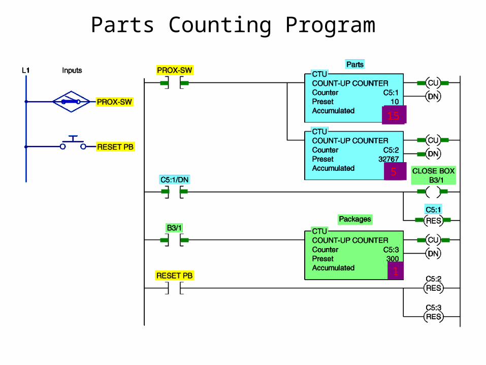
Parts Counting Program
9
9
10
10
1
15
5

DOWN- COUNTER
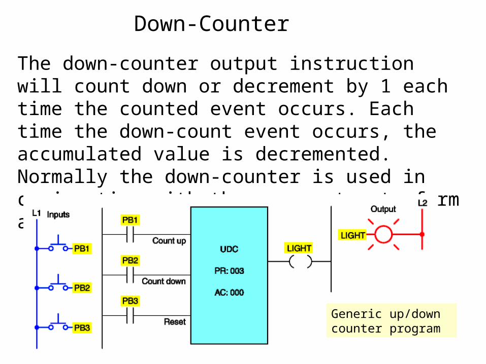
Down-Counter
The down-counter output instruction will count down or decrement by 1 each time the counted event occurs. Each time the down-count event occurs, the accumulated value is decremented. Normally the down-counter is used in conjunction with the up counter to form an up/down counter.
Generic up/down counter program
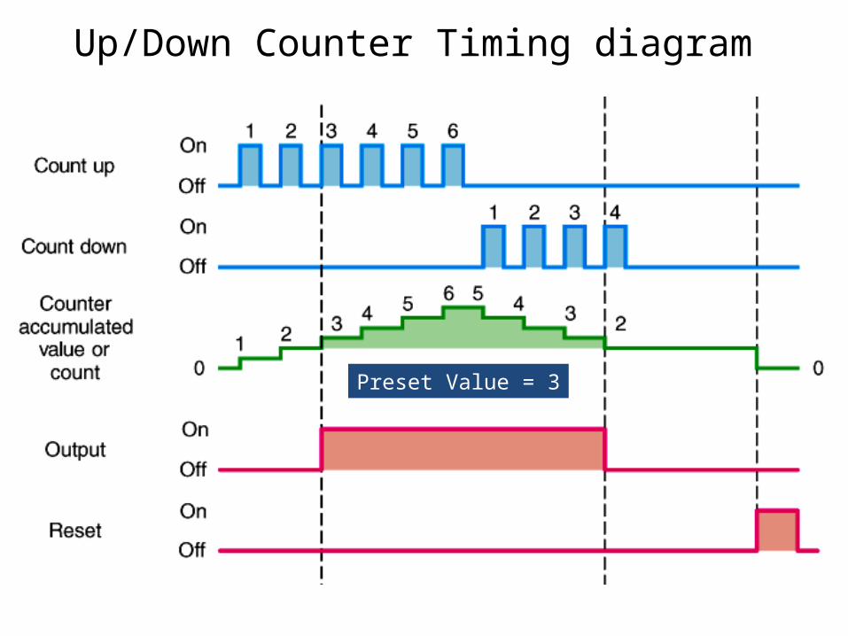
Up/Down Counter Timing diagram
Preset Value = 3

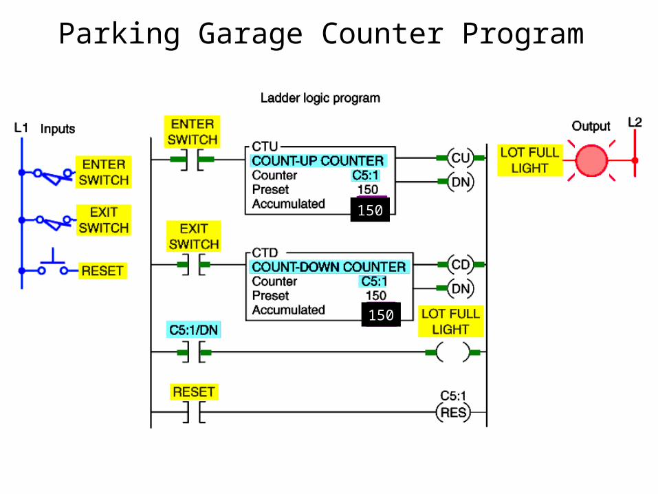
Parking Garage Counter Program
As a car enters, it triggers the up-counter output instruction andincrements the accumulated count by 1.
As a car leaves, it triggers the down-counter output instruction and decrements the accumulated count by 1.
Since both the up- and down-counters have the same address, the accumulated value will be the same in both.
Whenever the accumulated value equals the preset value, the counter output is energized to light up the Lot Full sign.
Parking Garage Counter Program
50
50
38
38
150
150

PLC-5 And SLC-500 Count-Down Counter Instruction
If the accumulation value is below the minimum range then the underflow (UN) bit will be true.
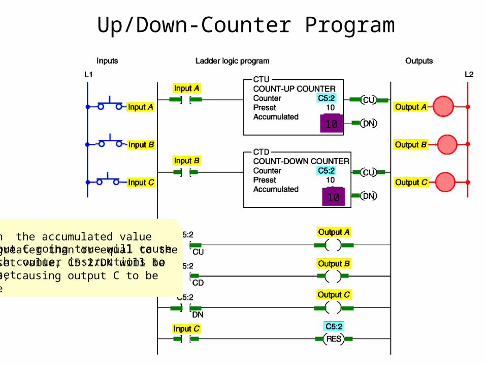
Up/Down-Counter Program
When the CTU instructionis true, C5:2/CU will be truecausing output A to be true
1
1
When the CTD instructionis true, C5:2/CD will be truecausing output B to be true
When the accumulated valueis greater than or equal to thepreset value, C5:2/DN will betrue, causing output C to betrue
10
10
Input C going true will cause both counter instructions to reset
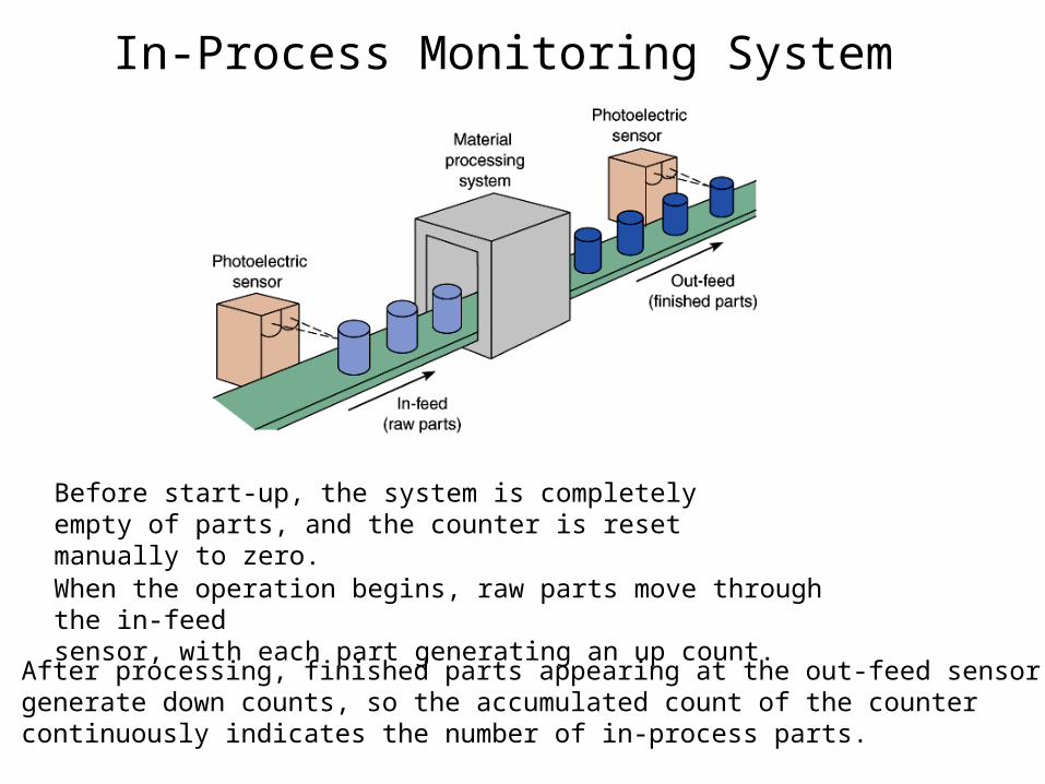
In-Process Monitoring System
Before start-up, the system is completely empty of parts, and the counter is reset manually to zero.
When the operation begins, raw parts move through the in-feedsensor, with each part generating an up count.
After processing, finished parts appearing at the out-feed sensorgenerate down counts, so the accumulated count of the countercontinuously indicates the number of in-process parts.

In-Process Monitoring System
8
8
5
5
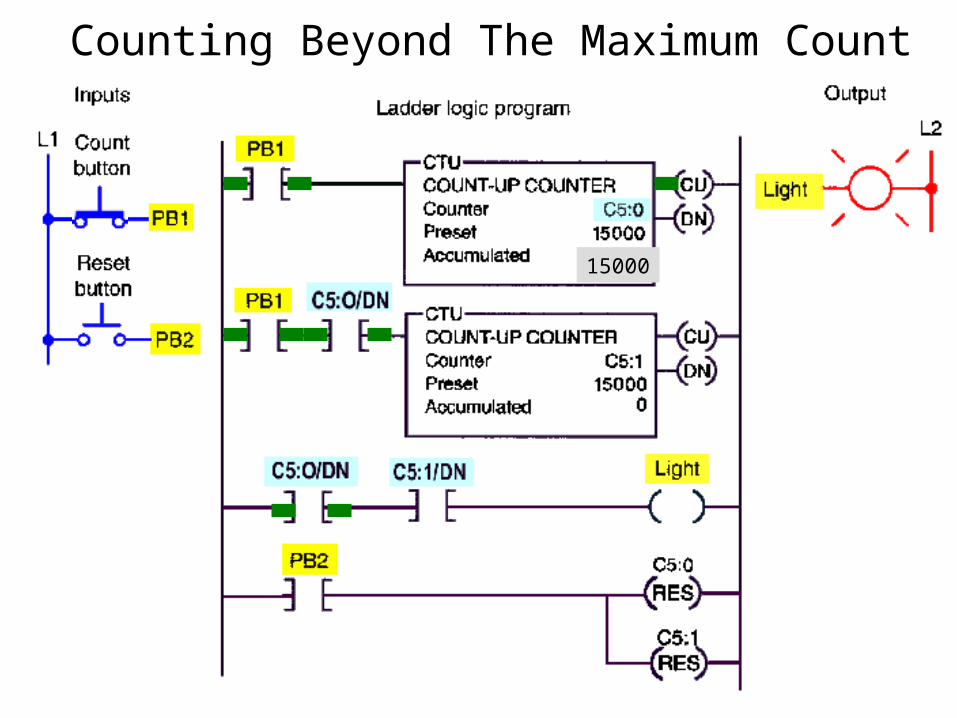
Counting Beyond The Maximum Count
15000
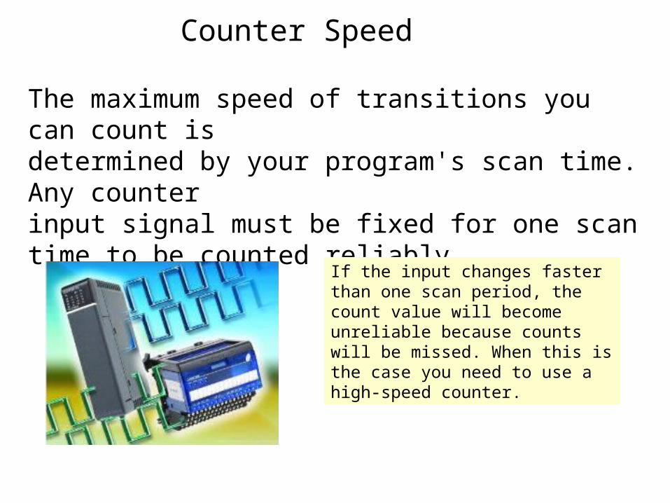
Counter Speed
The maximum speed of transitions you can count isdetermined by your program's scan time. Any counter input signal must be fixed for one scan time to be counted reliably.
If the input changes faster than one scan period, the count value will become unreliable because counts will be missed. When this is the case you need to use a high-speed counter.

CASCADING COUNTER

Cascading Counters
Depending on the application, it may be necessary to count events that exceed the maximum number allowable per counter instruction. One way of accomplishing this is by interconnection, or cascading, two counters.
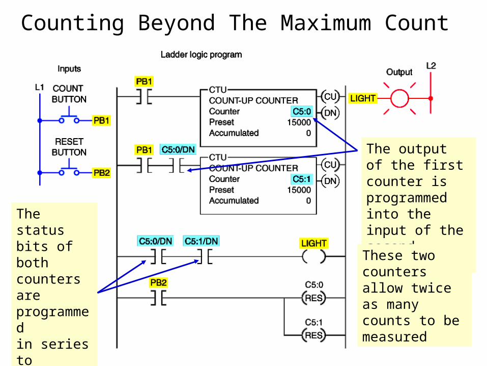
Counting Beyond The Maximum Count
The output of the first counter is programmed into the input of the second counterThe status
bits of both counters are programmed in series to produce an output
These two counters allow twice as many counts to be measured
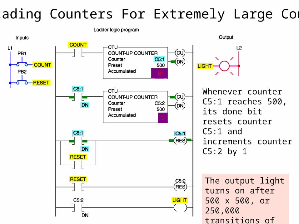
Cascading Counters For Extremely Large Counts
Whenever counter C5:1 reaches 500, its done bit resets counter C5:1 and increments counter C5:2 by 1
500
1
0
The output light turns on after 500 x 500, or 250,000 transitions of the count input