chapter 5 metering requirements - hk electric · chapter 5 metering requirements 5.1 general 1. all...
TRANSCRIPT

CHAPTER 5
METERING REQUIREMENTS

5.1
CHAPTER 5 METERING REQUIREMENTS 5.1 General 1. All installations connected to, or intended to be connected to HK
Electric’s supply of electricity must comply with HK Electric’s Supply Rules, the Electricity (Wiring) Regulations and other relevant Government Ordinances and Regulations.
2. Tariff metering equipment are important to HK Electric and customers in
the determination of electricity consumption. Tariff meters shall be installed in a clean and dry indoor location which is not exposed to weather, mechanical damage, vibrations, extremes of temperature or dampness, etc. They shall be under conditions which are suitable for meter installation, reading and maintenance and shall comply with requirements listed below.
5.2 Interference on Meter Seals Meter seals shall not be removed or tampered with by customer/REC/REW. A
fixed charge shall be levied on unauthorised interference. However, if rewiring of customer's installation requires removal of the seals, prior consultation with HK Electric shall be made.
5.3 Type of Meters to be Installed 1. For 11-kV/22-kV installation, transformer operated meter shall be installed.
2. For 3-phase 4-wire LV installation with main switch rating exceeding 125 A, C.T. operated meter shall be installed.
3. For 3-phase 4-wire LV installation with main switch rating of 125 A and
below, whole current meter shall be installed. 4. For single-phase LV installation, whole current meter shall be installed. 5.4 Metering Position 1. HK Electric’s 11-kV/22-kV current transformers and voltage transformers
shall be installed in HK Electric substation and HK Electric’s meter shall be installed inside the customer switchroom. Details of the arrangement are shown in Drg. Nos. GCS/5/01 and GCS/5/02.

5.2
2. HK Electric’s LV meter shall be electrically connected at a position immediately after the customer's main switch.
3. Meter position shall satisfy the requirements for meter reading, meter
fixing and meter maintenance. 4. The metering point of an installation shall be at a position as close to the
origin of the supply source as practicable. 5.5 General Requirements for Installation 1. Requirements for meter boards a. Meter board must be provided by the customer for installation of
meters and accessories. Meter board should preferably be of hard wood with varnish treatment and at least 12 mm thick, and the distance between the surface of meter board and wall surface shall not be less than 25 mm.
b. Fixing height of meter board (measured from the top of meter board
to finished floor level) shall be as follows: Meter Room/Switch Board Public Area Max. 2.25 m Max. 2.25 m Min. 0.90 m Min. 2.15 m c. Flat numbering shall be from left to right, top to bottom in ascending
order and be uniform throughout the building. d. A permanent, tidy and securely fixed flat/address label shall be
provided at the conspicuous space of each meter position. e. If holes are provided on meter boards for tariff meter leads and meter
tails to terminate onto a meter, there shall be two holes per tariff meter, left for incoming and right for customer's main cables.
f. For non-residential customers, meter board dimensions shall be
based on 3-phase meters of appropriate type. g. Meter boards and its clearance for more than one meter shall be of
dimensions in multiples of unit per Drg. No. GCS/5/14.

5.3
h. Meter board arrangements shall comply with Drg. Nos. GCS/5/15, GCS/5/16 and GCS/5/17 as appropriate.
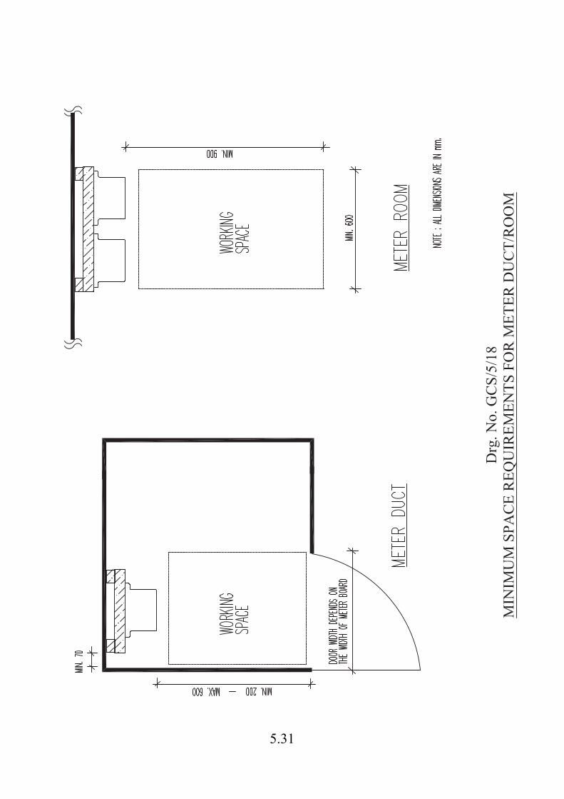
2. Requirements for meter ducts/rooms a. Space requirements for meter duct/room shall comply with Drg. No.
GCS/05/18. b. If meters are installed inside a meter duct with no free working
space inside, the distance between meter surface and the hinged door of the meter duct at closed position shall be maximum 600 mm and minimum 200 mm.
c. Minimum working space in front of the meter is 900 mm. Minimum
70 mm clearance is required by the side of the meter. d. In a multi-customer building, meter ducts/rooms shall be located at
public area. e. Meter duct/room shall be properly labelled, easily accessible and be
provided with locks. A master key exclusively for the use of all the meter duct/room locks shall be available at the Management Office to facilitate monthly meter reading. This master key shall not be able to open other locks.
f. Adequate lighting shall be provided inside the meter ducts/rooms. 5.6 General Requirements of LV Tariff Meters 1. Space requirement for tariff meters shall comply with Drg. No. GCS/5/14. 2. For main switch rating exceeding 125 A 3-phase and up to 400 A 3-phase,
HK Electric will provide a C.T. cum link box free of charge. The dimensions of the box are 305 mm x 375 mm x 175 mm (H x W x D). The working space in front of the box is 900 mm and the minimum clearance at the two sides of the box shall be 100 mm for sealing work.
3. For main switch rating exceeding 400 A 3-phase, the C.T. chamber as per
Drg. No. GCS/5/19 is required to be fitted into the switchboard cubicle. 4. C.T. operated meters shall be wired according to Drg. No. GCS/5/21.
Termination of multi-core cable at C.T.s and meter will be done by HK Electric.

5.4
5. Voltage wires of length around 500 mm should be prepared using the 12-core 4-mm2 cable provided by HK Electric. Wires with core number 7, 8, 9 and 10 should be connected to L1, L2, L3 and N respectively at the P2 (loading) side of corresponding measurement C.T. All exposed conductor of the voltage wires and customer main wires should be properly insulated by mastic tapes, covered with the correct colour coded tapes for phase identification.
6. For new installation of C.T. operated meters with a main switch rating of
600 A or above, located inside the customer switchboard, a Cat. 5e cable shall be supplied and installed by the customer with mechanical protection from the meter to the Tariff Meter Communication (TMC) Termination Box in the customer switchroom. Each end of the mechanical protection shall be terminated with a junction box inside which there should be at least 1-m spare length of the Cat. 5e cable. The junction boxes shall be within 0.5 m of the meter and the TMC Termination Box. This requirement should also apply for refurbishments of customer switchboards that contain C.T. operated meters with main switch rating of 600 A or above.
7. Where applicable, HK Electric shall provide the following LV metering
equipment free of charge:- - C.T. cum link box. - 12-core cable connecting C.T. terminals and tariff meter terminals.
The maximum length is 10 metres. - Cable gland for 12-core cable. - HRC fuse link carriers and bases. - Tariff metering C.T.s. REC / REW shall make advance appointment with us at 2887 3455 to
collect the above metering equipment from the Customer Centre on 9/F., Electric Centre, 28 City Garden Road, North Point, Hong Kong and install them properly before meter fixing.
8. For existing buildings, if the tariff meters are installed inside a meter
cubicle / enclosure, the meter cubicle / enclosure shall comply with the requirements as shown in Detail ‘A’ of Drg. No. GCS/5/22. Under special circumstances, HK Electric may accept the meter cubicle / enclosure which complies with the requirements as shown in Detail ‘B’ of Drg. No. GCS/5/22.

5.5
5.7 Special Requirements for 11-kV/22-kV Metering Scheme 1. HK Electric shall provide the following 11-kV/22-kV metering equipment
free of charge:- - 12-core cable for connection between V.T.s/C.T.s terminals and
tariff meter terminals. - Cable gland for 12-core cable. REC / REW shall make advance appointment with us at 2887 3455 to
collect the above metering equipment from the Customer Centre on 9/F., Electric Centre, 28 City Garden Road, North Point, Hong Kong and install them properly before meter fixing.
2. Space requirement for tariff meter shall comply with Drg. No. GCS/5/14. 3. The maximum length of metering cable connecting the V.T./C.T.
terminals and tariff meter terminal is 15 metres. The cable shall be properly laid and secured on cable trays.
4. A Cat. 5e cable shall be supplied and installed by the customer with
mechanical protection from the meter to the Tariff Meter Communication (TMC) Termination Box in the customer switchroom. Each end of the mechanical protection shall be terminated with a junction box inside which there should be at least 1-m spare length of the Cat. 5e cable. The junction boxes shall be within 0.5 m of the meter and the TMC Termination Box.
5. Ferruling of multi-core cable and termination of meter will be done by HK
Electric. 5.8 General Requirements of Current Transformer Chamber for
Accommodation of Metering C.T.s & Voltage Fuses 1. Recommended dimensions of C.T. chamber are as follows: Depth : 300 mm (Min.) Height : 400 mm (Min.) Width : vary with size of installation (see below)

5.6
Size of C.T.
C.T. Ratio Min. I.D. (mm)
Max. O.D. (mm)
Max. Thickness (mm)
Min. Width (mm)
200/5 A 60 110 80 500 400/5 A 60 110 80 500 1000/5 A 120 180 40 650 2000/5 A 130 180 40 650
2. C.T.s shall be generously spaced between busbars. They shall be rigidly
supported and insulated from live parts. 3. Bare copper bars shall be insulated by heat-shrinkable materials and
correctly coded for phase identification. 4. Voltage fuses and link shall be provided to protect and isolate voltage
supply to metering equipment. Details are: 3 pcs. GEC type SC32H fuse carrier and base (black) complete with
NS16 HRC fuse link. 1 pc. GEC type SC32H fuse carrier and base (white) complete with
NSC32A copper link. 5. Rigid supports shall be provided for mounting of conductor/busbar inside
the chamber. 6. Minimum space of 900 mm must be maintained in front of the C.T.
chamber for free access (full door swing) and as working space. 7. The sealable screw shall conform to Drg. No. GCS/5/19. 8. Multi-core cable between C.T. chamber and meter or meter panel will be
provided by HK Electric and installed in position by the REC/REW. 9. The requirement for cable mounted C.T. chamber shall be similar to that of
HK Electric's C.T. cum-link box. 10. Fixing height of C.T. chamber (measured from the top of C.T. chamber to
finished floor level) shall be as follows: Meter Room/Switch Board Public Area Max. 2.60 m Max. 2.60 m Min. 0.90 m Min. 2.15 m

5.7
5.9 Requirements for Meter Leads and Meter Tails
1. General
a. Size of meter leads and meter tails shall be according to the table as shown in Drg. No. GCS/5/14.
Minimum size of conductors used for termination onto HK
Electric’s whole current type meter shall be 4-mm2 stranded copper conductor.
b. The length of meter leads specified does not include customer’s
lateral mains. c. For the whole current type meter, the length of meter leads between
main switch and meter terminals shall not exceed 3 metres. d. Only circular, multi-stranded copper conductors are allowed for
termination onto HK Electric’s whole current type meters. Sector-shaped conductors are not allowed.
e. All meter leads and meter tails shall be correctly coded for phase
identification. 2. Phase Identification
a. Single-phase Meter Where new colour coded cable is used in meter leads and/or tails,
both meter leads and tails shall be fitted with proper, durable and legible phase identification labels (such as cable ties, sleeves, ferrules etc.) marked in L1 or L2 or L3 and N.
Where new and old colour coded cables are used separately in meter
leads and tails, a yellow warning notice in both English and Chinese shall be displayed at or close to the nearest upstream main switch/point of isolation. Details of the label shall comply with the Code of Practice for the Electricity (Wiring) Regulations.
b. Three-phase Meter
Where new colour coded cable is used in meter leads and tails, it is recommended that both meter leads and tails shall be fitted with proper, durable and legible phase identification labels (such as cable ties, sleeves, ferrules etc.) marked in L1, L2, L3 and N.

5.8
Where different colour coded cables are used in meter leads and tails, both the new and old colour coded cables shall be fitted with proper, durable and legible phase identification labels (such as cable ties, sleeves, ferrules etc.) marked in L1, L2, L3 and N. A yellow warning notice in both English and Chinese shall be displayed at or close to the nearest upstream main switch/point of isolation. Details of the label shall comply with the Code of Practice for the Electricity (Wiring) Regulations.
5.10 Ferrule Nos. for 12-core Cable
Core No. 1 2 3 4 5 6 7 8 9 10 11 12
Ferrule D11 D10 D31 D30 D51 D50 E11 E31 E51 E71 Spare
The ferrule nos. for 12-core cable apply to Summation and 11-kV/22-kV Metering Schemes only.
5.11 Special Summation Metering Scheme
The customer shall contact HK Electric to see whether their installation meets the requirements for special summation scheme. After the pre-requisites for special summation scheme are satisfied, technical details and quotations will then be forwarded to the customer for their consideration.
5.12 Removal of Meters and Related Services from a Building Due to Demolition
Before forwarding the request for meter disconnection and service removal, the developer/architect/contractor shall make sure that all the customers no longer need electricity supply and have vacated from the premises. The written request for meter disconnection and related services shall reach HK Electric at least six weeks before the intended service removal date. The developer/architect/contractor is also requested to return a duly completed Form TD 40 (Confirmation of No Asbestos Containing Material (ACM) Hazard) confirming that there is no ACM hazard at the specified period for our meter/service removal at the building to be demolished. HK Electric will arrange to remove our meters at the above building after the completion of the service removal works. The developer/architect/contractor is reminded not to interfere with or remove our meters. If our meters are in any way damaged or lost in the course of, or as a result of the works of the developer /architect/contractor, HK Electric shall hold the developer/architect/contractor fully liable for all losses and damage suffered by HK Electric including all cost incurred.

5.9
5.13 Metering Arrangement for Electric Vehicle Charging Facilities For details, please refer to Chapter 7 – Electric Vehicle Charging Facilities.
5.14 Schedule of Drawings – Metering Requirements Drawing No. Drawing Title GCS/5/01 General Metering Arrangement for Single 11-kV Supply GCS/5/02 General Metering Arrangement for Single 22-kV Supply GCS/5/03 General Metering Arrangement for Single Transformer
Supply GCS/5/04 Metering Arrangement for Two Transformer Supplies
with Bus-Section Circuit Breaker GCS/5/05 Metering Arrangement for Two Transformer Supplies
with Two Bus-Section Circuit Breakers GCS/5/06 General Metering Arrangement for Multi-Customer
Premises GCS/5/07 Metering Arrangement for Building Supply (Essential
Supply from Standby Generator) GCS/5/08 Metering Arrangement for Building Supply (Essential
Supply Tee-Off Before Building Main Switch) (Total 2 sheets) GCS/5/09 Incorrect Metering Arrangement for Building Supply GCS/5/10 Metering Arrangement for Building Supply (Two
Transformer Supplies with Bus-Section Circuit Breaker) (Total 2 sheets)
GCS/5/11 Incorrect Metering Arrangement for Building Supply
(Two Transformer Supplies with Bus-Section Circuit Breaker) (Total 2 sheets)
GCS/5/12 Metering Arrangement for Upper Floor Customers with
Dedicated Riser GCS/5/13 Metering Arrangement for Communal Electrical Supply
(No Essential Service) GCS/5/14 Tariff Meter Dimensions / Termination Clearance /
Meter Board / Leads Requirements

5.10
GCS/5/15 Typical Meter Board Arrangement GCS/5/16 Meter Board Arrangement for Public Area GCS/5/17 Meter Board Arrangement for Meter Room / Switch
Board GCS/5/18 Minimum Space Requirements for Meter Duct / Room GCS/5/19 Requirements for Metering Current Transformer
Chamber GCS/5/20 Metering Requirements for Main Switch Rating
exceeding 125 A and up to 400 A GCS/5/21 Wiring Diagram for C.T. Operated Meter GCS/5/22 Requirements for Meter Cubicle / Enclosure In Existing
Buildings

Drg. No. GCS/5/01GENERAL METERING ARRANGEMENT FOR SINGLE 11-kV SUPPLY
5.11

Drg. No. GCS/5/02GENERAL METERING ARRANGEMENT FOR SINGLE 22-kV SUPPLY
5.12

5.13

5.14

5.15

5.16

5.17

5.18

5.19

5.20

5.21

5.22

5.23

5.24

5.25

5.26

Drg. No. GCS/5/14TARIFF METER DIMENSIONS/TERMINATION CLEARANCE/METER
BOARD/LEADS REQUIREMENTS5.27

5.28

5.29

5.30
5.31

Drg
. No.
GC
S/5/
19R
EQU
IREM
ENTS
FO
R M
ETER
ING
CU
RR
ENT
TRA
NSF
OR
MER
CH
AM
BER
5.32

Drg. No. GCS/5/20METERING REQUIREMENTS FOR MAIN SWITCH RATING
EXCEEDING 125 A AND UP TO 400 A5.33

Drg
. No.
GC
S/5/
21W
IRIN
G D
IAG
RA
M F
OR
C.T
. OPE
RA
TED
MET
ER
5.34

Drg. No. GCS/5/22REQUIREMENTS FOR METER CUBICLE / ENCLOSURE
IN EXISTING BUILDINGS5.35