chapter 5 peer-to-peer protocols and data link layerand...
TRANSCRIPT

1
Chapter 5 Peer-to-Peer Protocols
and Data Link Layerand Data Link Layer
PART I: Peer-to-Peer ProtocolsPART II: Data Link Controls
Chapter Overview
Peer-to-Peer protocols: many protocols involve the interaction between two peers Service Models are discussed & examples given
Detailed discussion of ARQ provides example of development of peer-to-peer protocols
Flow control, TCP reliable stream, and timing recovery
Data Link LayerF i Framing
PPP & HDLC protocols
Queuing foundations

2
Peer-to-Peer Protocols
Peer-to-Peer processesexecute layer-n protocol to provide service to
n peer process n peer process
n + 1 peer process n + 1 peer process
player-(n+1)
Layer-(n+1) peer calls layer-n and passes Service Data Units (SDUs) for transfer
Layer n peers exchange
SDU SDU
PDU
n – 1 peer process n – 1 peer process
Layer-n peers exchange Protocol Data Units (PDUs) to effect transfer
Layer-n delivers SDUs to destination layer-(n+1) peer
Service Models
The service model specifies the information transfer service layer-n provides to layer-(n+1)
The most important distinction is if the service is: Connection-oriented
Connectionless
Service model possible features: Arbitrary message size or structure
Sequencing and Reliability
Timing and Flow control
Multiplexing
Privacy, integrity, and authentication

3
Reliability & Sequencing
Reliability: what transmission is reliable? Sequencing: Are messages or information stream Sequencing: Are messages or information stream
delivered in order?
duplication
How to provide reliable communication? Examples: TCP and HDLC
ARQ protocols combine error detection, retransmission, and sequence numbering to provide reliability & sequencing
Flow Control
What and Why flow control? If destination layer-(n+1) does not retrieve its
information fast enough, destination layer-n buffers may overflow
Flow Control provide backpressure mechanisms that control transfer according to gavailability of buffers at the destination
Examples: TCP and HDLC
4
Timing
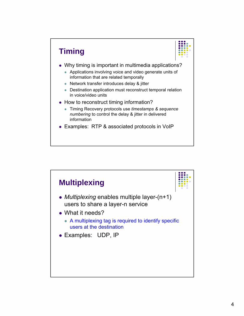
Why timing is important in multimedia applications? Applications involving voice and video generate units of g g
information that are related temporally
Network transfer introduces delay & jitter
Destination application must reconstruct temporal relation in voice/video units
How to reconstruct timing information? Timing Recovery protocols use timestamps & sequenceTiming Recovery protocols use timestamps & sequence
numbering to control the delay & jitter in delivered information
Examples: RTP & associated protocols in VoIP
Multiplexing
Multiplexing enables multiple layer-(n+1) users to share a layer-n serviceusers to share a layer n service
What it needs? A multiplexing tag is required to identify specific
users at the destination
Examples: UDP, IP

5
Privacy, Integrity, & Authentication
Privacy: ensuring that information transferred cannot be read by otherscannot be read by others
Integrity: ensuring that information is not altered during transfer
Authentication: verifying that sender and/or receiver are who they claim to be
Security protocols provide these services and are discussed in Chapter 11
Examples: IPSec, SSL
End-to-End vs. Hop-by-Hop
A service feature can be provided by implementing a protocol end-to-end across the network
across every hop in the network
Example: Perform error control at every hop in the network or only
between the source and destination?
Perform flow control between every hop in the network or Perform flow control between every hop in the network or only between source & destination?
We next consider the tradeoffs between the two approaches

6
(a)
Data link Data link
Packets Packets
Error control in Data Link Layer
Data Link operates over wire-like, di tl t dlayer
Physicallayer
Physicallayer
layerA B
Frames
3 2 11 2 3 11 2
(b)
directly-connected systems
Frames can be corrupted or lost, but arrive in order
Data link performs error-checking &
1
2
Physical layer entity
Data link layer entity
3 Network layer entity
3 2 11 2 3 2 11 2
21
Medium
A B
error checking & retransmission
Ensures error-free packet transfer between two systems
Error Control in Transport Layer
Transport layer protocol (e.g. TCP) sends segments across network and performs end-to-end error checking & retransmission
Networklayer
Networklayer
Networklayer
Networklayer
Transportlayer
Transportlayer
Messages Messages
Segments
Underlying network is assumed to be unreliable
Physicallayer
Data linklayer
Physicallayer
Data linklayer
End systemA
layer layer
Physicallayer
Data linklayer
layer
Physicallayer
Data linklayer
layer
End systemB
Network
Can segments experience long delays, be lost, out-of-order? Why?

7
Which Approach Preferred
Hop-by-hop cannot
Hop-by-hop (HDLC)
Simple
ensure E2E correctness
1 2 5Data
ACK/NAK
3Data
ACK/NAK
4Data
ACK/NAK
Data
ACK/NAK
End to end (TCP)
Faster recovery
In situations with infrequent or frequent errors, which one?
More scalable if complexity at the
edge
inside the network
1 2 5
Data
ACK/NAK
End-to-end (TCP)
3
Data
4
Data Data
Chapter 5Peer-to-Peer Protocols
and Data Link Layerand Data Link Layer
ARQ Protocols and Reliable Data Transfer

8
Purpose: to ensure a sequence of information packets is delivered in order and without errors or duplications despite transmission errors & losses
Automatic Repeat Request (ARQ)
duplications despite transmission errors & losses Sliding window: a set of Seq.# corresponding to frames
permitted to send / receive. We will look at:
Stop-and-Wait ARQ Go-Back N ARQ Selective Repeat ARQ Selective Repeat ARQ
Basic elements of ARQ: Error-detecting code with high error coverage ACKs (positive acknowledgments) NAKs (negative acknowledgments) Timeout mechanism
PacketError-free
packet
Stop-and-Wait ARQTransmit a frame, wait for ACK
p
Information frame
Control frame
Transmitter(Process A)
Receiver(Process B)Timer set after
each frame transmission
CRCInformation
packet
Header
Information frame Control frame: ACKs
CRCHeader
9
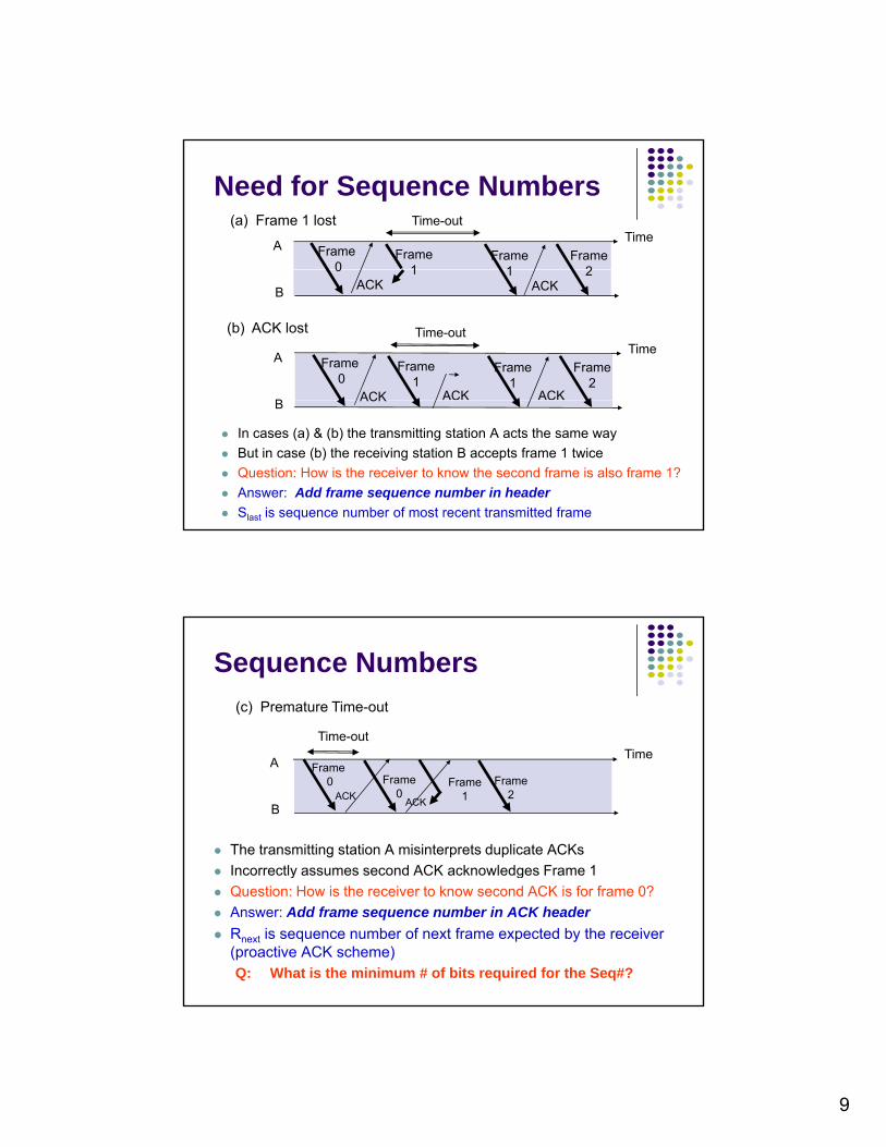
Need for Sequence Numbers(a) Frame 1 lost
A Frame 0
Frame1
Frame1
TimeTime-out
Frame2
B
0 1ACK
1ACK
2
(b) ACK lost
A
B
Frame 0
Frame1
ACK
Frame1
ACK
TimeTime-out
Frame2
ACK
In cases (a) & (b) the transmitting station A acts the same way
But in case (b) the receiving station B accepts frame 1 twice
Question: How is the receiver to know the second frame is also frame 1?
Answer: Add frame sequence number in header
Slast is sequence number of most recent transmitted frame
BACK
Sequence Numbers
(c) Premature Time-out
Time-out
The transmitting station A misinterprets duplicate ACKs
Incorrectly assumes second ACK acknowledges Frame 1
A
B
Frame 0 Frame
0ACKFrame
1ACK
Time
Frame2
y g
Question: How is the receiver to know second ACK is for frame 0?
Answer: Add frame sequence number in ACK header
Rnext is sequence number of next frame expected by the receiver (proactive ACK scheme)Q: What is the minimum # of bits required for the Seq#?

10
Stop-and-Wait ARQTransmitterReady state Await request from higher layer for
k t t f
ReceiverAlways in Ready State Wait for arrival of new frame
packet transfer When request arrives, transmit
frame with updated Slast and CRC Go to Wait StateWait state Wait for ACK or timer to expire;
block requests from higher layer If timeout expires
retransmit frame and reset timer If ACK received:
When frame arrives, check for errors If no errors detected and sequence
number is correct (Slast=Rnext), then accept frame, update Rnext, send ACK frame with Rnext, deliver packet to higher layer
If no errors detected and wrong sequence number discard frame
How?
If ACK received: If sequence number is incorrect or if
errors detected: ignore ACK If sequence number is correct (Rnext
= Slast +1): accept frame, go to Ready state
send ACK frame with Rnext
If errors detected discard frame
Can the protocol accept out-of-order frames? Why?
Applications of Stop-and-Wait ARQ
IBM Binary Synchronous Communications protocol (Bisync): character-oriented dataprotocol (Bisync): character oriented data link control
Xmodem: modem file transfer protocol
Trivial File Transfer Protocol (RFC 1350): simple protocol for file transfer over UDP

11
S&W ARQ Performance
Q1: consider a 50-kbps channel with a 500-msec round trip delay Frame size is 1000 bitmsec round-trip delay. Frame size is 1000-bit. What is the best bandwidth utilization (efficiency) of the one-bit sliding window protocol (stop-and-wait )?
Q2: A channel has a bit rate of 10 kbps and a propagation delay of 40 msec. For what range p p g y gof frame sizes does 1-bit sliding window give an bandwidth utilization (efficiency) of at least 50%? (L/(L+bR))
Stop-and-Wait Efficiency
First frame bit enters channel
Last frame bit enters channel
Channel idle while transmitter aits for ACK
ACK arrives
A
B
waits for ACK
Receiver First frame bit
t
t
10000 bit frame @ 1 Mbps takes 10 ms to transmit If wait for ACK = 1 ms, then efficiency = 10/11= 91% If wait for ACK = 20 ms, then efficiency =10/30 = 33%
Last frame bit arrives at receiver
processes frame and
prepares ACK
First frame bit arrives at receiver

12
Atproc
t0 = total time to transmit 1 frame
Stop-and-Wait Model
frametf time (nf/R)
B
tprop Tack (na/R)tproc tprop
proc
ttttt kf 220bits/info frame
R
n
R
ntt
ttttt
afprocprop
ackfprocprop
22
220bits/info frame
channel transmission rate
bits/ACK frame
S&W Efficiency on Error-free channel
bits for header & CRC
ndestinatiotodeli eredbitsninformatioofn mber nn
Effective transmission rate:
10 f
oof
eff nn
t
nnR
,bitsn informatio edeliver th torequired timetotal
ndestinatiotodeliveredbitsn informatio ofnumber
0
0
t
nnR of
eff
Effect offrame overhead
Transmission efficiency:
.)(2
10
f
procprop
f
a
n
Rtt
nnRR
Effect ofACK frame
Effect ofDelay-Bandwidth Product

13
Example: Impact of Delay-Bandwidth Product
nf=1250 bytes = 10000 bits, na=no=25 bytes = 200 bits
2 D l BW 1 10 100 12xDelayxBWEfficiency
1 ms
200 km(RTT dist.)
10 ms
2000 km
100 ms
20000 km
1 sec
200000 km
1 Mbps 103
88%
104
49%
105
9%
106
1%
1 Gbps 106 107 108 1091 Gbps 106
1%
107
0.1%
108
0.01%
109
0.001%
Stop-and-Wait does not work well for very high speeds or long propagation delays
S&W Efficiency in Channel with Errors
Let 1 – Pf = probability frame arrives w/o errors Avg. # of transmissions to first correct arrival is then 1/ (1–Pf ) “If 1-in-10 get through without error, then avg. 10 tries to
success” Avg. Total Time per frame is then t0/(1 – Pf)
11
0
f
o
f
of
eff nn
Pt
nn
R
)1()(2
1f
f
procprop
f
a
ffeffSW P
n
Rtt
n
nRR
Effect of frame loss

14
Example: Impact Bit Error Rate
nf=1250 bytes = 10000 bits, na=no=25 bytes = 200 bits
Find efficiency for random bit errors with p=0, 10-6, 10-5, 10-4y p
1 – Pf Efficiency
0 10-6 10-5 10-4
1 Mbps 1 0.99 0.905 0.368
pnepP fpnn
fff small and largefor )1(1
& 1 ms 88% 86.6% 79.2% 32.2%
Bit errors impact performance as nfp approach 1
S&W Performance Summary
General model: Given: the channel capacity b bits/sec, the frame size L bits, the round-trip propagation time R, p p p gsec. What is the time required to transmit a single frame? And what is the line utilization?
The combination of a long transit time (high RTT), high bandwidth, and short frame length gives bad efficiency to the protocol.
Piggybacking: why not have a free ride of ACK?
Pipelining: why not sending more frames before ACKs back?
What is the window size required if pipelining?
What is the price of pipelining, compared to S&W ARQ?
Piggybacking: why not have a free ride of ACK?

15
Piggybacking
Since in the two-way transmission, data frames and ACK frames are interleaving whyframes and ACK frames are interleaving, why not have a free ride of ACK upon a data delivering? How a receiver can tell if the frame is data or ACK?
For piggybacking, how long should the data link layer wait for a packet onto which to piggyback the ACK?ACK?
Transmitter A
Receiver B
Slast
Rnext
Piggybacking Example
What is the problem with the case (b)?
Two scenarios for protocol 4. (l) Normal case. (r) Abnormal case (simultaneous sending). The notation is (seq, ack, packet number). An asterisk indicates where a network layer accepts a packet.

16
Go-Back-N
Improve Stop-and-Wait by not waiting!
Keep channel busy by continuing to send framesKeep channel busy by continuing to send frames
Allow a window of up to Ws outstanding frames Receiver’s window size is often 1
Use m-bit sequence numbering
If ACK for oldest frame arrives before window is exhausted, we can continue transmitting, g
If window is exhausted, pull back and retransmit all outstanding frames
Alternative: Use timeout
Go-Back-N ARQ
fr Timefr fr fr fr fr fr fr
Go-Back-4: 4 frames are outstanding; so go back 4
fr frfr fr fr fr
A
B
0 1 2 3 4 5fr6 3
ACK
out of sequence frames
5fr64
fr7
fr8
fr9
ACK
ACK
ACK
ACK
ACK
ACK
ACK
ACK
Frame transmission are pipelined to keep the channel busy
Frame with errors and subsequent out-of-sequence frames are ignored
Transmitter is forced to go back when window of 4 is exhausted
K1
K2
K3
K4
K5
K6
K7
K8
K9
Rnext 0 1 2 3 3 4 5 6 7 8 9

17
Go-Back-N with Timeout
Problem with Go-Back-N as presented: Window size should be long enough to cover round trip time
If a frame is lost and source does not have a frame to send, then window will not be exhausted and recovery will not commence
Use a timeout with each frame When timeout expires, resend all outstanding frames
Timefr0
fr0
Time-out expiresfr1
A
B
0 0 1
ACK1
Receiver is looking for
Rnext=0
Maximum Window Size
Given N-bit seq. numbers, what is the maximum number of frames that can be outstanding in “go back N”?
MAX_SEQ = 2^m – 1 while there are 2^m sequence numbers. Should the maximum number be MAX_SEQ or MAX_SEQ + 1?
Example: m = 2; sequence numbers: 0, 1, 2, 3
1) The sender sends 4 frames 0 through 3
2) A piggybacked ACK for frame 3 eventually back to sender
3) The sender sends another 4 frames (0 through 3)) ( g )
4) Another piggybacked ACK for frame 3 back to sender
Can the sender tell if all 4 frames in second batch got received or all got lost?

18
Afr0
Timefr1
fr2
fr3
fr0
fr1
fr2
fr3
M = 22 = 4, Go-Back - 4: Transmitter goes back 4
Maximum Allowable Window Size is Ws = 2m-1
B ACK1
ACK0
ACK2
ACK3
Receiver has Rnext= 0, but it does not know whether its ACK for frame 0 was received, so it does not know whether this is the old frame 0 or a new frame 0Rnext 0 1 2 3 0
Afr0
Timefr fr2
fr0
fr1
fr2
M = 22 = 4, Go-Back-3: Transmitter goes back 3
A
B
0 1 2 0 1 2
ACK1
ACK2
ACK3
Receiver has Rnext= 3 , so it rejects the old frame 0
Rnext 0 1 2 3 The sequence of frame exchange.
Applications of Go-Back-N ARQ
HDLC (High-Level Data Link Control): bit-oriented data link controloriented data link control
V.42 modem: error control over telephone modem links
19
Tproc
Tout
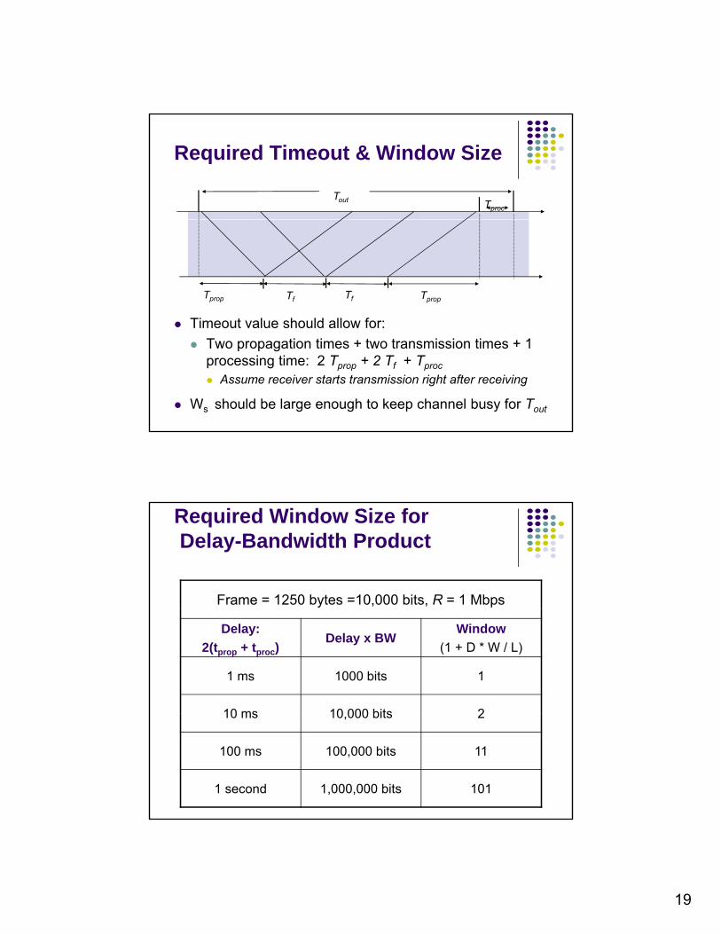
Required Timeout & Window Size
Tf Tf TpropTprop
Timeout value should allow for: Timeout value should allow for:
Two propagation times + two transmission times + 1 processing time: 2 Tprop + 2 Tf + Tproc
Assume receiver starts transmission right after receiving
Ws should be large enough to keep channel busy for Tout
Frame = 1250 bytes =10,000 bits, R = 1 Mbps
Required Window Size forDelay-Bandwidth Product
Delay:
2(tprop + tproc)Delay x BW
Window
(1 + D * W / L)
1 ms 1000 bits 1
10 ms 10 000 bits 210 ms 10,000 bits 2
100 ms 100,000 bits 11
1 second 1,000,000 bits 101
20
Selective Repeat ARQ
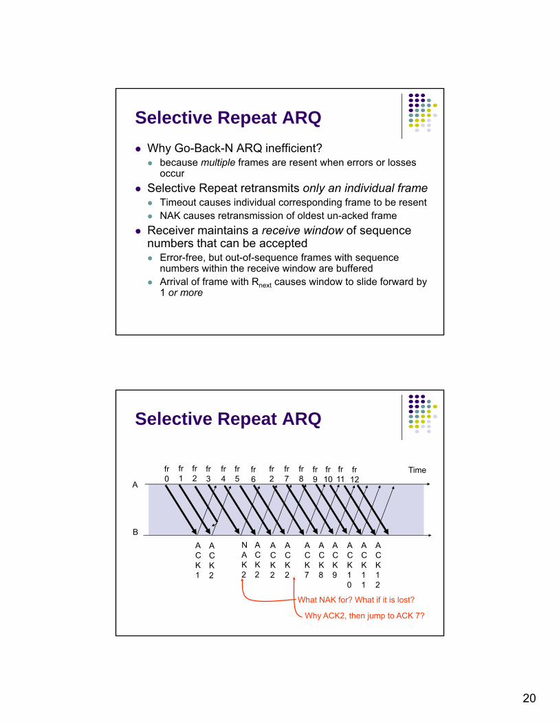
Why Go-Back-N ARQ inefficient? because multiple frames are resent when errors or losses
occur
Selective Repeat retransmits only an individual frame Timeout causes individual corresponding frame to be resent NAK causes retransmission of oldest un-acked frame
Receiver maintains a receive window of sequence numbers that can be accepted Error-free, but out-of-sequence frames with sequence
numbers within the receive window are buffered Arrival of frame with Rnext causes window to slide forward by
1 or more
fr Timefr fr fr fr fr fr fr fr frfr fr fr fr
Selective Repeat ARQ
A
B
0Time
1 2 3 4 5fr6 2
AC
8fr97
fr10
fr11
fr12
AC
NA
AC
AC
AC
AC
AC
AC
AC
AC
ACC
K1
CK2
AK2
CK7
CK8
CK9
CK10
CK11
CK12
CK2
CK2
CK2
What NAK for? What if it is lost?
Why ACK2, then jump to ACK 7?

21
What size Ws and Wr allowed?
Example (as in Go-back N): M=22=4, Ws=3, Wr=3Frame 0 resent
A
B
fr0Time
fr1 fr2 fr0
ACK1 ACK2 ACK3
{0,1,2} {1,2} {2} {.}Send
Window
ACK1 ACK2 ACK3
{0,1,2} {1,2,3}Receive Window {2,3,0} {3,0,1}
Old frame 0 accepted as anew frame because it fallsin the receive window
What is the essence of the problem? and what to do?
after the receiver advanced its window, the new range of valid sequence # overlapped with the old one. The receiver cannot distinguish a duplicate from a new frame.
Ws + Wr = 2m is maximum allowed
Example: M=22=4, Ws=2, Wr=2
Frame 0 resent
A
B
fr0Time
fr1 fr0
Frame 0 resent
{0,1} {1} {.}Send
Window
B ACK1 ACK2
{0,1} {1,2}Receive Window
{2,3}
Old frame 0 rejected because it falls outside the receive window

22
Applications of Sel. Repeat ARQ
TCP (Transmission Control Protocol): transport layer protocol uses variation oftransport layer protocol uses variation of selective repeat to provide reliable stream service
Service Specific Connection Oriented Protocol: error control for signalingProtocol: error control for signaling messages in ATM networks
Efficiency of Selective Repeat
Atproc
t0 = total time to transmit 1 frame
Assume Pf frame loss probability, then number of transmissions required to deliver a frame is 1/(1-P ):
frametf time (nf/R)
B
tprop Tack (na/R)tproc tprop
proc
transmissions required to deliver a frame is 1/(1-Pf): Average transmission time: tf /(1-Pf)
)1)(1()1/(
ff
off
of
SR Pn
n
R
Pt
nn

23
Example: Impact Bit Error Rate on Selective Repeat
nf=1250 bytes = 10000 bits, na=no=25 bytes = 200 bits
Compare S&W, GBN & SR efficiency for random bit errors p ywith p=0, 10-6, 10-5, 10-4 and R= 1 Mbps & 100 ms
Efficiency 0 10-6 10-5 10-4
S&W 8.9% 8.8% 8.0% 3.3%
GBN 98% 88 2% 45 4% 4 9%GBN 98% 88.2% 45.4% 4.9%
SR 98% 97% 89% 36%
Selective Repeat outperforms GBN and S&W, but efficiency drops as error rate increases
Comparison of ARQ Efficiencies
Assume na and no are negligible relative to nf, andL = 2(tprop+tproc)R/nf =(Ws-1), then
Selective-Repeat:
Go-Back-N:
f
f
f
fGBN LP
P
PW
P
1
1
)1(1
1
)1()1)(1( ff
ofSR P
n
nP
For Pf≈0, SR & GBN same
Stop-and-Wait:
L
P
n
Rtt
nn
P f
f
procprop
f
a
fSW
1
1
)(21
)1(
ffS LPPW 1)1(1
For Pf→1, GBN & SW same

24
Chapter 5Peer-to-Peer Protocols
and Data Link Layerand Data Link Layer
PART II: Data Link ControlsFraming
Point-to-Point ProtocolHigh-Level Data Link ControlHigh Level Data Link Control
Link Sharing Using Statistical Multiplexing
Data Link Protocols
Data Links Services Framing Error controlData link Data link
Packets Packets
Error control Flow control Multiplexing Link Maintenance Security: Authentication &
Encryption
Examples
Data linklayer
Physicallayer
Physicallayer
Data linklayer
A BFrames
Directly connected, wire-like Losses & errors, but no out-of-
sequence frames Applications: Direct Links;
LANs; Connections across WANs
Examples PPP HDLC Ethernet LAN IEEE 802.11 (Wi Fi) LAN

25
Framing
Framing: to break the bit stream up into discrete
receivedframes
transmittedframes stream up into discrete
frames and compute the checksum for each frame Mapping stream of physical
layer bits into frames Mapping frames into bit
stream
Frame boundaries can be
Framing
framesframes
Why framing?
Frame boundaries can be determined using: Control Characters Flags CRC Checks (GFP)
0110110111
0111
1101
01
Framing & Bit Stuffing
Flag FlagAddress Control Information FCS
HDLC frame
Frame delineated by flag character HDLC uses bit stuffing to prevent occurrence of flag
01111110 inside the frame Transmitter inserts extra 0 after each consecutive
fi 1 i id th f
any number of bits
five 1s inside the frame Receiver checks for five consecutive 1s if next bit = 0, it is removed if next two bits are 10, then flag is detected If next two bits are 11, then frame has errors

26
0110111111111100
Data to be sent(a)
Example 1
0110111111111100
After stuffing and framing
0111111001101111101111100001111110
Data received(b)
*011011111-11111-00*
After destuffing and deframing
011111101101111101111100001111110
Q: How a bit loss be detected in bit
Example 2
stuffing? Can it always be detected?

27
Flag Byte with Byte Stuffing
What happens if the payload field contains the flag byte?
Flag byte starts and ends each frame (used in PPP).
(a) A frame delimited by flag bytes.
(b) Four examples of byte sequences before and after stuffing.
PPP: Point-to-Point Protocol
Data link protocol for point-to-point lines in Internet Router-router; dial-up to router
A home personal computer acting as an internet host.

28
PPP Functionalities
1. Provides Framing and Error Detection Character-oriented HDLC-like frame structure Character oriented HDLC like frame structure
2. Link Control Protocol (LCP) Set up, testing, maintaining, bringing down lines;
negotiating options
Authentication: key capability in ISP access
3 A f il f N t k C t l P t l (NCP)3. A family of Network Control Protocols (NCP) specific to different network layer protocols IP, OSI network layer, IPX (Novell), Appletalk
PPP Applications
PPP used in many point-to-point applications Telephone Modem Links Telephone Modem Links Packet over SONET IP→PPP→SONET
PPP is also used over shared links such as Ethernet to provide LCP, NCP, andEthernet to provide LCP, NCP, and authentication features PPP over Ethernet (RFC 2516) Used over DSL
29
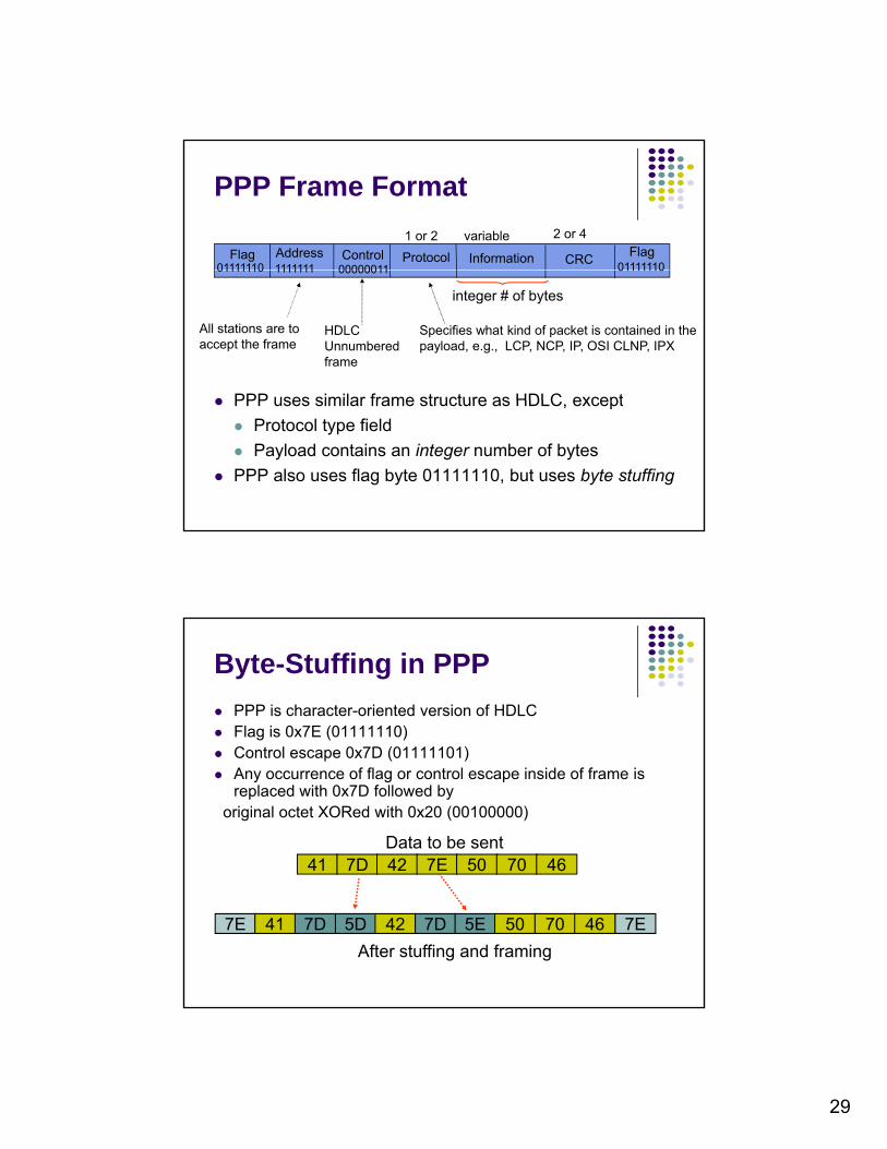
PPP Frame Format
Flag FlagAddress Control Information CRCProtocol01111110 011111101111111 00000011
1 or 2 variable 2 or 4
PPP uses similar frame structure as HDLC except
01111110 011111101111111 00000011
HDLC Unnumbered frame
Specifies what kind of packet is contained in the payload, e.g., LCP, NCP, IP, OSI CLNP, IPX
All stations are toaccept the frame
integer # of bytes
PPP uses similar frame structure as HDLC, except
Protocol type field
Payload contains an integer number of bytes
PPP also uses flag byte 01111110, but uses byte stuffing
PPP is character-oriented version of HDLC Flag is 0x7E (01111110)
C t l 0 7D (01111101)
Byte-Stuffing in PPP
Control escape 0x7D (01111101) Any occurrence of flag or control escape inside of frame is
replaced with 0x7D followed byoriginal octet XORed with 0x20 (00100000)
Data to be sent41 7D 42 7E 50 70 46
After stuffing and framing
5D 42 7D 5E 50 70 467E 41 7D 7E

30
High-Level Data Link Control (HDLC)
Bit-oriented data link control Derived from IBM Synchronous Data Link Control (SDLC)y ( )
Networklayer
Networklayer
DLPDU
NLPDU
“Packet”
DLSAP DLSAP
Physicallayer
Data linklayer
Data linklayer
Physicallayer
DLPDU
“Frame”
Normal Response Mode Used in polling multidrop lines
HDLC Data Transfer Modes
Commands
Asynchronous Balanced Mode
PrimaryCommands
Responses
Secondary Secondary Secondary
Used in full-duplex point-to-point links
Primary
Secondary
Commands Responses
Primary
Secondary
CommandsResponses
Mode is selected during connection establishment

31
HDLC Frame Format
Flag FlagAddress Control Information FCS
Control field gives HDLC its functionality Codes in fields have specific meanings and uses
Flag: delineate frame boundaries Address: identify secondary station (1 or more bytes)
In ABM mode, a station can act as primary or secondary so address changes accordingly
g g
address changes accordingly Control: purpose & functions of frame (1 or 2 bytes) Information: contains user data; length not standardized, but
implementations impose maximum Frame Check Sequence: 16- or 32-bit CRC
Frames lost due to loss-of-synch or receiver buffer overflow
Error Detection & Loss Recovery
Frames may undergo errors in transmission
CRCs detect errors and such frames are treated as lost
Recovery through ACKs, timeouts & retransmission
Sequence numbering to identify out-of-sequence & duplicate framesduplicate frames
HDLC provides for options that implement several ARQ methods