chapter 5 protection circuit design · snubber circuits can be classified into two types:...
TRANSCRIPT
Chapter 5
Protection Circuit Design
5-1
CONTENTS Page
1 Short circuit (overcurrent) protection ………………………… 5-2
2 Overvoltage protection ………………………… 5-6
This section explains the protection circuit design.
Chapter 5 Protection Circuit Design
5-2
1 Short circuit (overcurrent) protection
1.1 Short circuit withstand capability In the event of a short circuit, first the IGBT’s collector current will rise, once it has reached a certain
level, the C-E voltage will spike. Depending on the device’s characteristics, during the short-circuit, the collector current can be kept at or below a certain level, however the IGBT will still continue to be subjected to a heavy load, that is, high voltage and high current. Therefore, this condition must be removed as soon as possible.
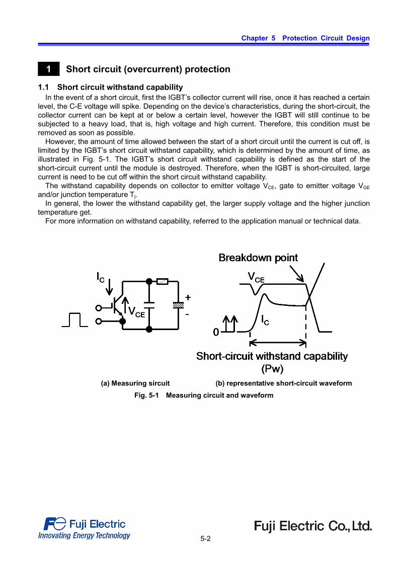
However, the amount of time allowed between the start of a short circuit until the current is cut off, is limited by the IGBT’s short circuit withstand capability, which is determined by the amount of time, as illustrated in Fig. 5-1. The IGBT’s short circuit withstand capability is defined as the start of the short-circuit current until the module is destroyed. Therefore, when the IGBT is short-circuited, large current is need to be cut off within the short circuit withstand capability.
The withstand capability depends on collector to emitter voltage VCE, gate to emitter voltage VGE and/or junction temperature Tj.
In general, the lower the withstand capability get, the larger supply voltage and the higher junction temperature get.
For more information on withstand capability, referred to the application manual or technical data.
(a) Measuring sircuit (b) representative short-circuit waveform Fig. 5-1 Measuring circuit and waveform

Chapter 5 Protection Circuit Design
5-3
1.2 Short-circuit modes and causes Table 5-1 lists the short-circuit modes and causes that occur in inverters.
Table 5-1 Short circuit mode and cause
Short circuit mode Cause Arm short circuit
Transistor or diode destruction
Series arm short circuit
Faulty control/drive circuit or noise induce malfunction
Short in output circuit
Miswiring or dielectric breakdown of load
Ground fault
Miswiring or dielectric breakdown of load
Chapter 5 Protection Circuit Design
5-4
1.3 Short-circuit (overcurrent) detection 1) Detection in the circuit
As stated previously, in the event of a short-circuit, the IGBT must be disabled as soon as possible. Therefore, the time from overcurrent detection to the complete turn-off in each circuit must be as short as possible.
Since the IGBT turns off very quickly, if the overcurrent is shut off using an ordinary drive signal, the
collector-emitter voltage will rise due to the inductive kick, and the IGBT may be destroyed by overvoltage (RBSOA destructions). Therefore, it is recommended that when cutting off the overcurrent that the IGBT be turned off gently (Soft turn-off).
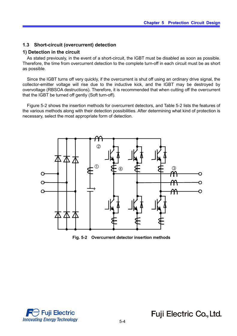
Figure 5-2 shows the insertion methods for overcurrent detectors, and Table 5-2 lists the features of
the various methods along with their detection possibilities. After determining what kind of protection is necessary, select the most appropriate form of detection.
+
Fig. 5-2 Overcurrent detector insertion methods
Chapter 5 Protection Circuit Design
5-5
Table 5-2 Overcurrent detector insertion positions and function Detector insertion position Features Detection function Insertion in line with smoothing capacitor Fig.5-2/
• AC current transformer available • Low detection precision
• Arm short-circuit • Short in output circuit • Series arm short-circuit • Ground fault
Insertion at inverter input Fig.5-2/
• Necessary to use DC current transformer
• Low detection precision
• Arm short-circuit • Short in output circuit • Series arm short-circuit • Ground fault
Insertion at inverter output Fig.5-2/
• AC current transformer available for high frequency output equipment
• High detection precision
• Short in output circuit • Ground fault
Insertion in line with switches Fig.5-2/
• Necessary to use DC current transformer
• High detection precision
• Arm short-circuit • Short in output circuit • Series arm short-circuit • Ground fault
2) Detecting using VCE(sat)
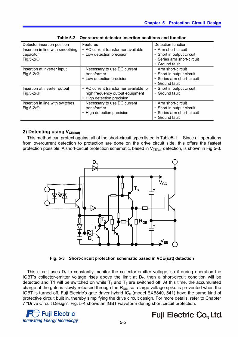
This method can protect against all of the short-circuit types listed in Table5-1. Since all operations from overcurrent detection to protection are done on the drive circuit side, this offers the fastest protection possible. A short-circuit protection schematic, based in VCE(sat) detection, is shown in Fig.5-3.
Fig. 5-3 Short-circuit protection schematic based in VCE(sat) detection
This circuit uses D1 to constantly monitor the collector-emitter voltage, so if during operation the
IGBT’s collector-emitter voltage rises above the limit at D2, then a short-circuit condition will be detected and T1 will be switched on while T2 and T3 are switched off. At this time, the accumulated charge at the gate is slowly released through the RGE, so a large voltage spike is prevented when the IGBT is turned off. Fuji Electric’s gate driver hybrid ICS (model EXB840, 841) have the same kind of protective circuit built in, thereby simplifying the drive circuit design. For more details, refer to Chapter 7 “Drive Circuit Design”. Fig. 5-4 shows an IGBT waveform during short circuit protection.
+
+
VCC
VEED2
T1
T2
T3
RGE
D1
+
+
VCC
VEED2
T1
T2
T3
RGE
D1

Chapter 5 Protection Circuit Design
5-6
2MBI300UD-120
Ed=600V, VGE=+15V, –5V (EXB841), RG=3.3Ω, Tj=125°C
VCE=200V/div, IC=250A, VGE=10V/div, t=2μs/div Fig. 5-4 Waveforms during short circuit protection
2 Overvoltage protection
2.1 Overvoltage causes and their suppression 1) Overvoltage causes
Due to the high switching speed of IGBTs, at turn-off or during FWD reverse recovery, the current change rate (di/dt) is very high. Therefore the circuit wiring inductance to the module can cause a high turn-off surge voltage (V=L(di/dt)).
At an example, using the IGBT’s waveform at turn-off we will introduce the causes and methods of their suppression, as well as illustrate a concrete example of a circuit (using an IGBT and FWD together).
To demonstrate the turn-off surge voltage, a simplified chopper circuit is shown in Fig. 5-5, and the IGBT turn-off voltage and current waveforms are shown in Fig. 5-6.

Chapter 5 Protection Circuit Design
5-7
Ls
IGBT1FWD1
FWD2IGBT2
L0
R0
LoadVGE1
VCE1
IC1
ID2(=-IC2)
VD2(=-VCE2)
Ed
Ls
IGBT1FWD1
FWD2IGBT2
L0
R0
LoadVGE1
VCE1
IC1
ID2(=-IC2)
VD2(=-VCE2)
Ls
IGBT1FWD1
FWD2IGBT2
L0
R0
LoadVGE1
VCE1
IC1
ID2(=-IC2)
VD2(=-VCE2)
Ed
Ed: DC supply voltage, LS: Main circuit wiring inductance, Load:L0,R0
Fig. 5-5 Chopper circuit
VGE1
VCE1IC1
VGE1
VCE1
VD2(= VCE2)
IC1
ID2
0
0
0
VCESP2
VCESP1
(1) Waveforms of reverse recovery. (2) Waveforms of turn-off.
IGBT turn on
FWD reverse recovery
VGE1
VCE1IC1
VGE1
VCE1
VD2(= VCE2)
IC1
ID2
0
0
0
VCESP2
VCESP1
(1) Waveforms of reverse recovery. (2) Waveforms of turn-off.
IGBT turn on
VGE1
VCE1IC1
VGE1
VCE1
VD2(= VCE2)
IC1
ID2
0
0
0
VCESP2
VCESP1
(1) Waveforms of reverse recovery. (2) Waveforms of turn-off.
IGBT turn on
FWD reverse recovery
Fig. 5-6 Switching waveforms
The turn-off surge voltage peak VCESP can be calculated as follows:
)/( dtdIcLEdV SCESP •−+= ···················· dIc/dt: Maximum collector current change rate at turn-off If VCESP exceeds the IGBT’s C-E (VCES) rating, then the module will be destroyed.

Chapter 5 Protection Circuit Design
5-8
2) Overvoltage suppression methods
Several methods for suppressing turn-off surge voltage, the cause for overvoltage, are listed below: a. Control the surge voltage by adding a protection circuit (snubber circuit) to the IGBT.
Use a film capacitor in the snubber circuit, place it as close as possible to the IGBT in order to bypass high frequency surge currents.
b. Adjust the IGBT drive circuit’s – VGE or RG in order to reduce the di/dt value. (Refer to Chapter 7, “Drive Circuit Design”.)
c. Place the electrolytic capacitor as close as possible to the IGBT in order to reduce the effective inductance of the wiring. Use a low impedance capacitor.
d. To reduce the inductance of the main as well as snubber circuit’s wiring, use thicker and shorter wires. It is also very effective to use laminated copper bars in the wring.
2.2 Types of snubber circuits and their features
Snubber circuits can be classified into two types: individual and lump. Individual snubber circuits are connected to each IGBT, while lump snubber circuits are connected between the DC power-supply bus and the ground for centralized protection. 1) Individual snubber circuits
Examples of typical individual snubber circuits are listed below. a) RC snubber circuit b) Charge and discharge RCD snubber circuit c) Discharge-suppressing RCD snubber circuit
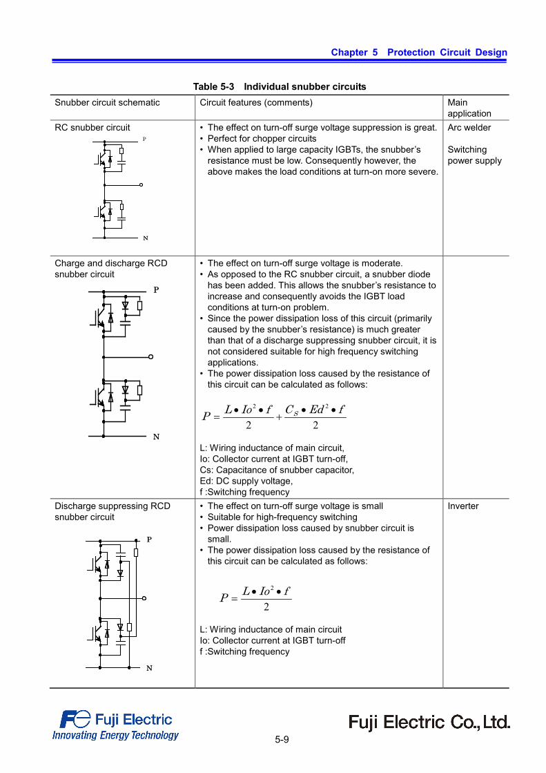
Table 5-3 shows the schematic of each type of individual snubber circuit, its features, and an outline
of its main uses. 2) Lump snubber circuits
Examples of typical snubber circuits are listed below. a) C snubber circuits b) RCD snubber circuits
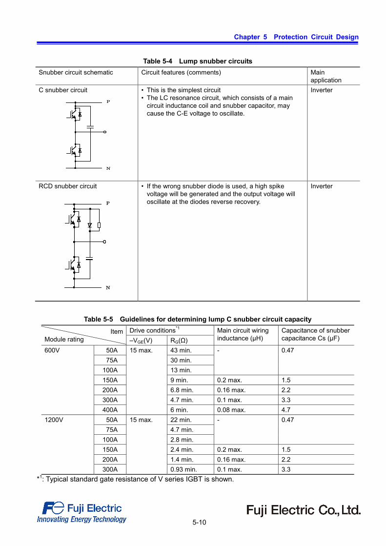
Lump snubber circuits are becoming increasingly popular due to circuit simplification. Table 5-4 shows the schematic of each type of lump snubber circuit, its features, and an outline of its
main applications. Table 5-5 shows the capacity selection of a C type snubber circuit. Fig. 5-7 shows the current and voltage turn-off waveforms for an IGBT connected to a lump snubber circuit.
Chapter 5 Protection Circuit Design
5-9
Table 5-3 Individual snubber circuits Snubber circuit schematic
Circuit features (comments) Main application
RC snubber circuit
• The effect on turn-off surge voltage suppression is great. • Perfect for chopper circuits • When applied to large capacity IGBTs, the snubber’s
resistance must be low. Consequently however, the above makes the load conditions at turn-on more severe.
Arc welder Switching power supply
Charge and discharge RCD snubber circuit
• The effect on turn-off surge voltage is moderate. • As opposed to the RC snubber circuit, a snubber diode
has been added. This allows the snubber’s resistance to increase and consequently avoids the IGBT load conditions at turn-on problem.
• Since the power dissipation loss of this circuit (primarily caused by the snubber’s resistance) is much greater than that of a discharge suppressing snubber circuit, it is not considered suitable for high frequency switching applications.
• The power dissipation loss caused by the resistance of this circuit can be calculated as follows:
L: Wiring inductance of main circuit, Io: Collector current at IGBT turn-off, Cs: Capacitance of snubber capacitor, Ed: DC supply voltage, f :Switching frequency
Discharge suppressing RCD snubber circuit
• The effect on turn-off surge voltage is small • Suitable for high-frequency switching • Power dissipation loss caused by snubber circuit is
small. • The power dissipation loss caused by the resistance of
this circuit can be calculated as follows:
L: Wiring inductance of main circuit Io: Collector current at IGBT turn-off f :Switching frequency
Inverter
NN
P
P
N
P
N 22
22 fEdCfIoLP S ••+
••=
P
N
P
N
2
2 fIoLP ••=
Chapter 5 Protection Circuit Design
5-10
Table 5-4 Lump snubber circuits Snubber circuit schematic Circuit features (comments) Main
application C snubber circuit
• This is the simplest circuit • The LC resonance circuit, which consists of a main
circuit inductance coil and snubber capacitor, may cause the C-E voltage to oscillate.
Inverter
RCD snubber circuit
• If the wrong snubber diode is used, a high spike voltage will be generated and the output voltage will oscillate at the diodes reverse recovery.
Inverter
Table 5-5 Guidelines for determining lump C snubber circuit capacity
Item Module rating
Drive conditions*1 Main circuit wiring inductance (μH)
Capacitance of snubber capacitance Cs (μF) –VGE(V) RG(Ω)
600V 50A 15 max. 43 min. - 0.47 75A 30 min.
100A 13 min. 150A 9 min. 0.2 max. 1.5 200A 6.8 min. 0.16 max. 2.2 300A 4.7 min. 0.1 max. 3.3 400A 6 min. 0.08 max. 4.7
1200V 50A 15 max. 22 min. - 0.47 75A 4.7 min.
100A 2.8 min. 150A 2.4 min. 0.2 max. 1.5 200A 1.4 min. 0.16 max. 2.2 300A 0.93 min. 0.1 max. 3.3
*1: Typical standard gate resistance of V series IGBT is shown.
P
N
P
N
P
N
P
N

Chapter 5 Protection Circuit Design
5-11
2.3 Discharge-suppressing RCD snubber circuit design
The discharge suppressing RCD can be considered the most suitable snubber circuit for IGBTs. Basic design methods for this type of circuit are explained in the following. 1) Study of applicability
Figure 5-8 is the turn-off locus waveform of an IGBT in a discharge-suppressing RCD snubber circuit. Fig. 5-9 shows the IGBT current and voltage waveforms at turn-off.
VCESP VCEP VCES
VCE
IC
(pulse)RBSOA
VCESP VCEP VCES
VCE
IC
(pulse)RBSOA
Fig. 5-8 Turn-off locus waveform of IGBT
Fig. 5-7 Current and voltage waveforms of IGBT in lump snubber circuit at turn-off
2MBI300VN-120-50 VGE=+15V/-15V Vcc=600V, Ic=300A Rg=0.93Ω, Ls=80nH
Vce,Ic=0
Vge =0
Vge : 20V/div Vce : 200V/div Ic : 100A/div Time : 200nsec/div

Chapter 5 Protection Circuit Design
5-12
The discharge-suppressing RCD snubber circuit is activated when the IGBT C-E voltage starts to exceed the DC supply voltage. The dotted line in diagram Fig. 5-8 shows the ideal operating locus of an IGBT. In an actual application, the wiring inductance of the snubber circuit or a transient forward voltage drop in the snubber diode can cause a spike voltage at IGBT turn-off. This spike voltage causes the sharp-cornered locus indicated by the solid line in Fig. 5-8.
The discharge-suppressing RCD snubber circuits applicability is decided by whether or not the IGBTs operating locus is within the RBSOA at turn-off.
The spike voltage at IGBT turn-off is calculated as follows:
)/( dtdIcLVEdV SFMCESP •−++= ···········
Ed: Dc supply voltage VFM: Transient forward voltage drop in snubber diode
The reference values for the transient forward voltage drop in snubber diodes is as follows: 600V class: 20 to 30V 1200V class: 40 to 60V
Ls: Snubber circuit wiring inductance dIc/dt: Maximum collector current change rate a IGBT turn-off 2) Calculating the capacitance of the snubber capacitor (Cs)
The necessary capacitance of a snubber capacitor is calculated as follows:
( )22
EdVIoLC
CEPS
−•
= ·································
L: Main circuit wiring inductance Io: Collector current at IGBT turn-off VCEP: Snubber capacitor peak voltage Ed: DC supply voltage
VCEP must be limited to less than or equal to the IGBT C-E withstand voltage.
IC
IO VCESP VCEP
VCE
IC
IO VCESP VCEP
VCE
Fig. 5-9 Voltage and current waveforms at turn-off
Chapter 5 Protection Circuit Design
5-13
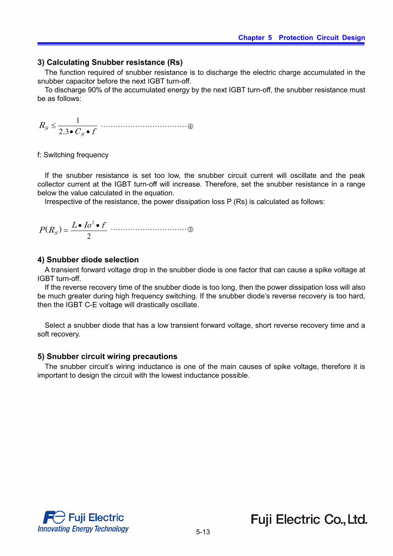
3) Calculating Snubber resistance (Rs) The function required of snubber resistance is to discharge the electric charge accumulated in the
snubber capacitor before the next IGBT turn-off. To discharge 90% of the accumulated energy by the next IGBT turn-off, the snubber resistance must
be as follows:
fCR
SS ••≤
321
. ···································
f: Switching frequency
If the snubber resistance is set too low, the snubber circuit current will oscillate and the peak collector current at the IGBT turn-off will increase. Therefore, set the snubber resistance in a range below the value calculated in the equation.
Irrespective of the resistance, the power dissipation loss P (Rs) is calculated as follows:
2
2 fIoLRP S••
=)( ·······························
4) Snubber diode selection
A transient forward voltage drop in the snubber diode is one factor that can cause a spike voltage at IGBT turn-off.
If the reverse recovery time of the snubber diode is too long, then the power dissipation loss will also be much greater during high frequency switching. If the snubber diode’s reverse recovery is too hard, then the IGBT C-E voltage will drastically oscillate.
Select a snubber diode that has a low transient forward voltage, short reverse recovery time and a
soft recovery. 5) Snubber circuit wiring precautions
The snubber circuit’s wiring inductance is one of the main causes of spike voltage, therefore it is important to design the circuit with the lowest inductance possible.

Chapter 5 Protection Circuit Design
5-14
2.4 Example of characteristic of spike voltage
The spike voltage shows various behaviors depending on the operation, drive and circuit conditions.
Generally, the spike voltage becomes higher when the collector voltage is higher, the circuit inductance is larger, and the collector current is larger. As an example of spike voltage characteristic, the current dependence of spike voltage at IGBT turn-off and FWD reverse recovery is shown in Figure 5-10.
As this figure shows, the spike voltage at IGBT turn-off becomes higher when the collector current is higher, but the spike voltage at FWD reverse recovery becomes higher when the current is low. Generally, the spike voltage during reverse recovery becomes higher when the collector current is in the low current area that is a fraction of the rated current.
The spike voltage shows various behaviors depending on the operation, drive and circuit conditions. Therefore, make sure that the current and voltage can be kept within the RBSOA described in the specification in any expected operating condition of the system.
400
600
800
1000
1200
1400
1600
0 200 400 600 800 1000Collector current (A)
Spi
ke v
olta
ge (V
)
2MBI450VN-120-50(1200V / 450A)
Vge=+15V/-15VVcc=600VIc=vari.Rg=0.52 ohmLs=60nHTj=125deg.C
VCEPVAKP
Fig. 5-10 Spike voltages dependency on collector current
Chapter 5 Protection Circuit Design
5-15
2.5 Spike voltage suppression circuit - clamp circuit -
In general, spike voltage generated between collector
to emitter can be suppressed by means of decreasing the stray inductance or installing snubber circuit. However, it may be difficult to decrease the spike voltage under the hard operating conditions.
For this case, it is effective to install the active clamp circuits, which is one of the spike voltage suppressing circuits.
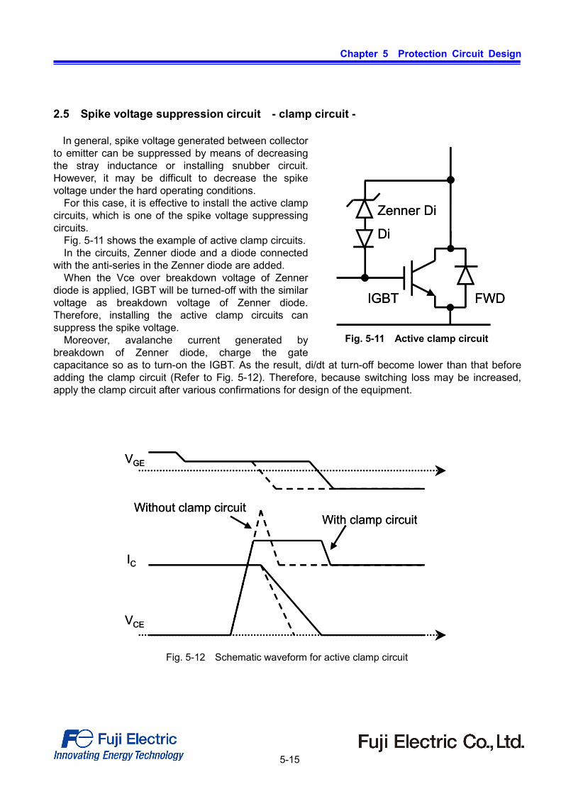
Fig. 5-11 shows the example of active clamp circuits. In the circuits, Zenner diode and a diode connected
with the anti-series in the Zenner diode are added. When the Vce over breakdown voltage of Zenner
diode is applied, IGBT will be turned-off with the similar voltage as breakdown voltage of Zenner diode. Therefore, installing the active clamp circuits can suppress the spike voltage.
Moreover, avalanche current generated by breakdown of Zenner diode, charge the gate capacitance so as to turn-on the IGBT. As the result, di/dt at turn-off become lower than that before adding the clamp circuit (Refer to Fig. 5-12). Therefore, because switching loss may be increased, apply the clamp circuit after various confirmations for design of the equipment.
FWD
Zenner Di
Di
IGBT FWD
Zenner Di
Di
IGBT
Fig. 5-11 Active clamp circuit
VGE
VCE
IC
With clamp circuitWithout clamp circuit
VGE
VCE
IC
With clamp circuitWithout clamp circuit
Fig. 5-12 Schematic waveform for active clamp circuit

1. This Catalog contains the product specifications, characteristics, data, materials, and structures as of January 2017. The contents are subject to change without notice for specification changes or other reasons. When using a product listed in this Catalog, be sur to obtain the latest specifications.
2. All applications described in this Catalog exemplify the use of Fuji's products for your reference only. No right or license, either express or implied, under any patent, copyright, trade secret or other intellectual property right owned by Fuji Electric Co., Ltd. is (or shall be deemed) granted. Fuji Electric Co., Ltd. makes no representation or warranty, whether express or implied, relating to the infringement or alleged infringement of other's intellectual property rights which may arise from the use of the applications described herein.
3. Although Fuji Electric Co., Ltd. is enhancing product quality and reliability, a small percentage of semiconductor products may become faulty. When
using Fuji Electric semiconductor products in your equipment, you are requested to take adequate safety measures to prevent the equipment from causing a physical injury, fire, or other problem if any of the products become faulty. It is recommended to make your design failsafe, flame retardant, and free of malfunction.
4. The products introduced in this Catalog are intended for use in the following electronic and electrical equipment which has normal reliability
requirements. ・Computers ・OA equipment ・Communications equipment (terminal devices) ・Measurement equipment ・Machine tools ・Audiovisual equipment ・Electrical home appliances ・Personal equipment ・Industrial robots etc. 5. If you need to use a product in this Catalog for equipment requiring higher reliability than normal, such as for the equipment listed below, it is
imperative to contact Fuji Electric Co., Ltd. to obtain prior approval. When using these products for such equipment, take adequate measures such as a backup system to prevent the equipment from malfunctioning even if a Fuji's product incorporated in the equipment becomes faulty.
・Transportation equipment (mounted on cars and ships) ・Trunk communications equipment ・Traffic-signal control equipment ・Gas leakage detectors with an auto-shut-off feature ・Emergency equipment for responding to disasters and anti-burglary devices ・Safety devices ・Medical equipment 6. Do not use products in this Catalog for the equipment requiring strict reliability such as the following and equivalents to strategic equipment (without
limitation). ・Space equipment ・Aeronautic equipment ・Nuclear control equipment ・Submarine repeater equipment 7. Copyright ©1996-2011 by Fuji Electric Co., Ltd. All rights reserved.
No part of this Catalog may be reproduced in any form or by any means without the express permission of Fuji Electric Co., Ltd. 8. If you have any question about any portion in this Catalog, ask Fuji Electric Co., Ltd. or its sales agents before using the product.
Neither Fuji Electric Co., Ltd. nor its agents shall be liable for any injury caused by any use of the products not in accordance with instructions set forth herein.
WARNING