chapter 5 specific energy - İtÜweb.itu.edu.tr/~bulu/hydraulics_files/lecture_notes_05.pdf ·...
TRANSCRIPT
Prof. Dr. Atıl BULU 1
Chapter 5
Specific Energy
5.1. Introduction The total energy of a channel flow referred to datum is given by,
gVyzH2
2
++= (5.1)
If the datum coincides with the channel bed at the cross-section, the resulting expression is know as specific energy and is denoted by E. Thus, specific energy is the energy at a cross-section of an open channel flow with respect to the channel bed. The concept of specific energy, introduced by Bakmeteff, is very useful in defining critical water depth and in the analysis of open channel flow. It may be noted that while the total energy in a real fluid flow always decreases in the downstream direction, the specific energy is constant for a uniform flow and can either decrease or increase in a varied flow, since the elevation of the bed of the channel relative to the elevation of the energy line, determines the specific energy. Specific energy at a cross-section is,
2
22
22 gAQy
gVyE +=+= (5.2)
Here, cross-sectional area A depends on water depth y and can be defined as, A = A(y). Examining the Equ. (5.2) show us that, there is a functional relation between the three variables as,
0),,( =QyEf (5.3)
In order to examine the functional relationship on the plane, two cases are introduced.
1. Q = Constant = Q1 → E = f (y, Q1).
Variation of the specific energy with the water depth at a cross-section for a given discharge Q1.
2. E = Constant = E1 → E1 = f (y,Q)
Variation of the discharge with the water depth at across-section for a given specific energy E1.
Prof. Dr. Atıl BULU 2
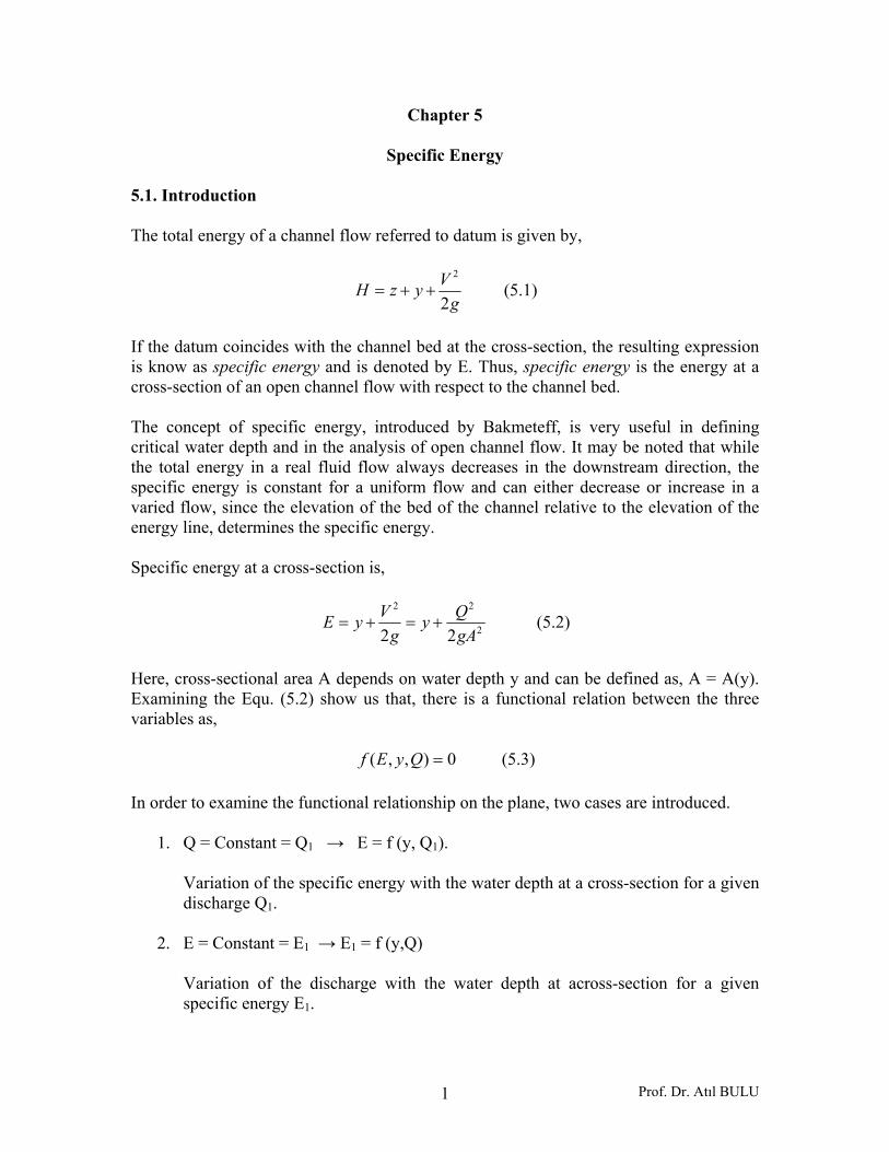
5.2. Constant Discharge Situation Since the specific energy,
2
22
22 gAQy
gVyE +=+=
Figure 5.1. Specific energy diagram For a channel of known geometry, E = f (y, Q). Keeping Q = constant = Q1, the variation of E with y is represented by a cubic parabola. (Figure 5.1). It is seen that there are two positive roots for the equation E indicating that any particular discharge Q1 can be passed in a given channel at two depths and still maintain the same specific energy E1. The depths of flow can be either PR = y1 or PR` = y`1. These two possible depths having the same specific energy are known as alternate depths. In Fig. (5.1), a line (OS) drawn such that E = y (i.e. at 450 to the abscissa) is the asymptote of the upper limb of the specific energy curve. It may be noticed that the intercept P`R` and P`R represents the velocity head. Of the two alternate depths, one (PR = y1) is smaller and has a large velocity head while the other (PR`= y`1) has a larger depth and consequently a smaller velocity head. For a given Q, as the specific energy is increased the difference between the two alternate depths increases. On the other hand, if E is decreased, the difference (y`1 – y1) will decrease and a certain value E = Ec, the two depths will merge with each other (point C in Fig. 5.1). No value for y can be obtained when E < Ec , denoting that the flow under the given conditions is not possible in this region. The condition of minimum specific energy is known as the critical flow condition and the corresponding depth yc is known as critical depth. At critical depth, the specific energy is minimum. Thus differentiating Equ. (5.2) with respect to y (keeping Q1 constant) and equating to zero,
01 3
21 =×−=
dydA
gAQ
dydE
Prof. Dr. Atıl BULU 3
But,
=== Tdy
TdydydA Top width, width of the channel at the water surface
Designating the critical flow conditions by the suffix (c),
13
21 =
c
c
gATQ (5.4)
Equ. (5.4) is the basic equation governing the critical flow conditions in a channel. It may be noted that the critical flow condition is governed solely by the channel geometry and discharge. Other channel characteristics such as the bed slope and roughness do not influence the critical flow condition for any given Q. If the Froude number of the flow is defined as,
TAg
VFr = (5.5)
111
1
22
13
21
=→=→=
=→=
rcrc
c
c
c
ccc
c
FF
TAg
V
VAQ
gATQ
(5.6)
The critical flow corresponds to the minimum specific energy and at this condition the Froude number of the flow is unity. Referring to Fig. (5.1), considering any specific energy other than Ec, (say ordinate PP` at E = E1) the Froude number of the flow corresponding to both the alternate depths will be different from unity as y1 or y`1 ≠ yc. At lower limb, CR of the specific energy curve is the supercritical flow region.
0.1111 >→>→< rcc FVVyy
The upper limb CR` is the subcritical flow region,
0.1111 <′→<′→>′ rcc FVVyy
Prof. Dr. Atıl BULU 4
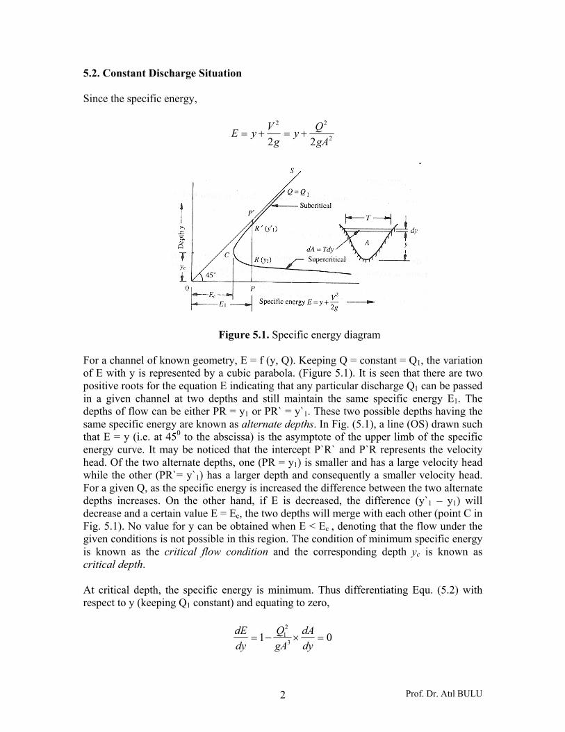
Rectangular Cross-Section
Figure 5.2
For a rectangular channel, A = By, and T = B,
22
2
2 ygBQyE +=
==BQq Discharge per unit width
32
3
2
2
2
01
2
cygq
gyq
dydE
gyqyE
=
=−=
+=
32
gqyc = (5.7)
32
cygq
=
2
3
min
2
2
min
2
2
cc
cc
yyyE
gyqyE
+=
+=
cyE 5.1min = (5.8)
c
c
cccc y
gyyq
ByQ
AQV
3
====
cc gyV = (5.9)
y
T=B
Prof. Dr. Atıl BULU 5
Critical slope for the critical water depth yc,
5.032
5.032
21
21
cc
cc
cc
cc
SyB
Byyn
qBQ
SyB
Byn
ByAVQ
⎟⎟⎠
⎞⎜⎜⎝
⎛+
==
⎟⎟⎠
⎞⎜⎜⎝
⎛+
==
(5.10)
is calculated from Equ. (5.10). Triangular Channel
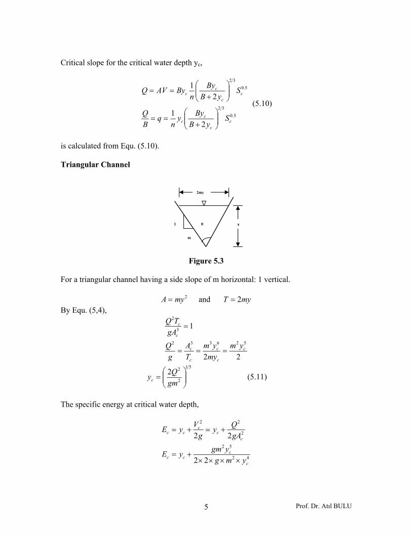
Figure 5.3
For a triangular channel having a side slope of m horizontal: 1 vertical.
2myA = and myT 2= By Equ. (5,4),
22
1
526332
3
2
c
c
c
c
c
c
c
ymmy
ymTA
gQ
gATQ
===
=
51
2
22⎟⎟⎠
⎞⎜⎜⎝
⎛=
gmQyc (5.11)
The specific energy at critical water depth,
42
52
2
22
22
22
c
ccc
cc
ccc
ymgygmyE
gAQy
gVyE
××××+=
+=+=
y
m
1
2my
θ

Prof. Dr. Atıl BULU 6
cc
cc yyyE 25.14=+= (5.12)
The Froude number for a triangular channel is,
mymyg
V
TAg
VFr
2
2==
gyVFr
2= (5.13)
Example 5.1: A rectangular channel 2.50 m wide has a specific energy of 1.50 m when carrying a discharge of 6.48 m3/sec. Calculate the alternate depths and corresponding Froude numbers. Solution: From Equ. (5.2),
22
2
22
22
50.281.9248.650.1
22
yy
ygBQy
gVyE
×××+=
+=+=
234243.050.1y
y +=
Solving this equation by trial and error, the alternate depths y1 and y2 are obtained as,
y1 = 1.30 m and y2 = 0.63 m
Froude number,
23828.0
81.950.248.6
yyyF
gyByQ
BBygA
Q
TAg
VF
r
r
==
===
56.030.1828.030.1 50.111 ==→= rFy → Subcritical flow
67.163.0828.063.0 50.122 ==→= rFy →Supercritical flow
Prof. Dr. Atıl BULU 7
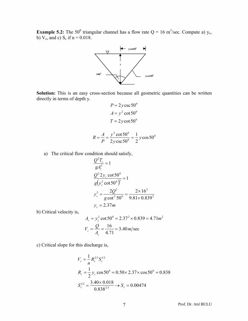
Example 5.2: The 500 triangular channel has a flow rate Q = 16 m3/sec. Compute a) yc, b) Vc, and c) Sc if n = 0.018.
Solution: This is an easy cross-section because all geometric quantities can be written directly in terms of depth y.
0
02
0
50cot250cot50csc2
yTyA
yP
=
=
=
0
0
02
50cos21
50csc250cot y
yy
PAR ===
a) The critical flow condition should satisfy,
( )
myg
Qy
ygyQ
gATQ
c
c
c
c
c
c
37.2839.081.9
16250cot
2
150cot
50cot2
1
2
2
02
25
302
02
3
2
=××
==
=
=
b) Critical velocity is,
sec40.371.4
1671.4839.037.250cot 2202
mAQV
myA
cc
cc
===
=×==
c) Critical slope for this discharge is,
00474.0838.0
018.040.3
838.050cos37.250.050cos21
1
3221
00
2132
=→×
=
=××==
=
cc
cc
ccc
SS
yR
SRn
V
ycot500
ycsc500
y
1000
Prof. Dr. Atıl BULU 8
Example 5.3: A flow of 5.0 m3/sec is passing at a depth of 1.50 through a rectangular channel of width 2.50 m. What is the specific energy of the flow? What is the value of the alternate depth to the existing depth? Solution:
mg
VyE
mg
V
mAQV
60.110.050.12
10.062.19
33.12
sec33.150.250.1
0.5
21
11
221
11
=+=+=
==
=×
==
For the alternate depth,
( )
60.1204.0
60.15.281.92
0.5
22
2
22
2
2
=+
=××
+
yy
my
y
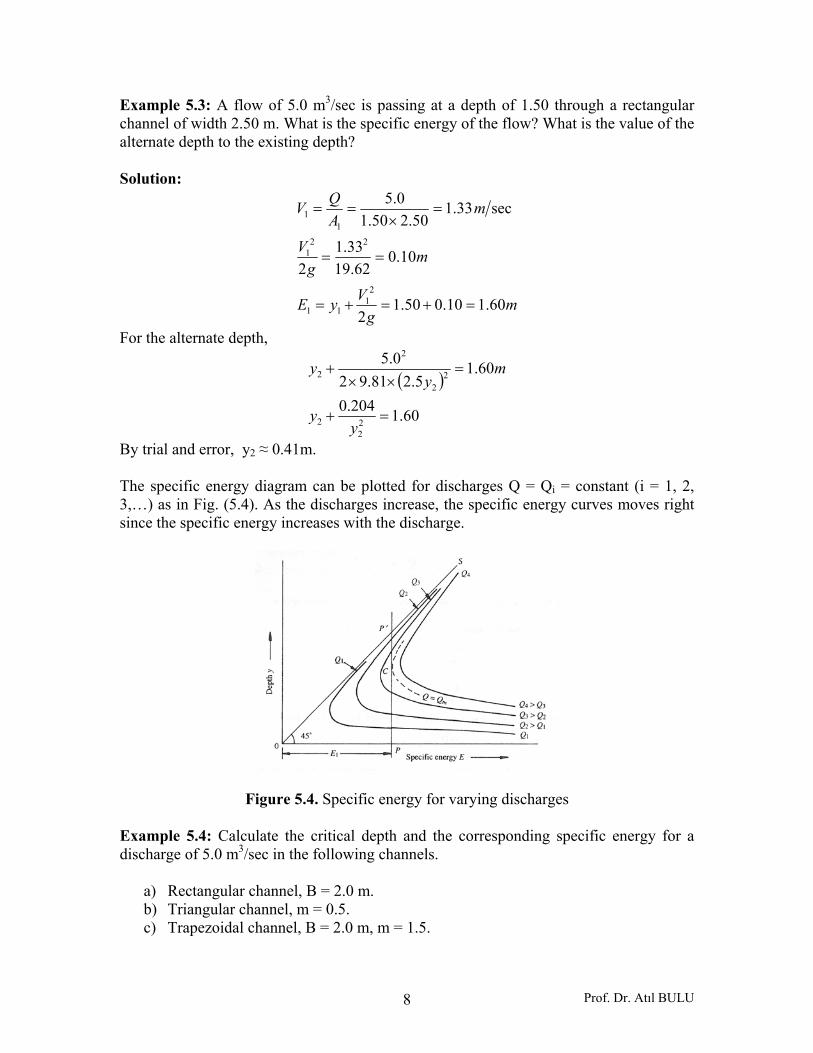
By trial and error, y2 ≈ 0.41m. The specific energy diagram can be plotted for discharges Q = Qi = constant (i = 1, 2, 3,…) as in Fig. (5.4). As the discharges increase, the specific energy curves moves right since the specific energy increases with the discharge.
Figure 5.4. Specific energy for varying discharges Example 5.4: Calculate the critical depth and the corresponding specific energy for a discharge of 5.0 m3/sec in the following channels.
a) Rectangular channel, B = 2.0 m. b) Triangular channel, m = 0.5. c) Trapezoidal channel, B = 2.0 m, m = 1.5.
Prof. Dr. Atıl BULU 9
Solution:
a) Rectangular channel
mgqy
mmBQq
c 86.081.950.2
sec//5.20.20.5
312312
3
=⎟⎟⎠
⎞⎜⎜⎝
⎛=⎟⎟
⎠
⎞⎜⎜⎝
⎛=
===
myE cc 29.186.05.15.1 =×== b) Triangular channel
From Equ. (5.11),
83.15.081.9
0.52
2
51
2
2
51
2
2
=⎟⎟⎠
⎞⎜⎜⎝
⎛×
×=
⎟⎟⎠
⎞⎜⎜⎝
⎛=
c
c
y
gmQy
myE cc 29.283.125.125.1 =×== c) Trapezoidal Channel
( )( )myBT
ymyBA2+=
+=
( )( )c
cc
c
myBymyB
gQ
TA
gQ
2
332
32
++
=
=
( )( )c
cc
yyy
5.120.25.10.2
81.90.5 332
×+×+
=
By trial and error,
myc 715.0=
( )
sec27.220.20.5
20.2715.0715.05.10.2 2
mV
mA
c
c
==
=××+=
mE
gVyE
c
ccc
98.062.19
27.2715.0
22
2
=+=
+=
Prof. Dr. Atıl BULU 10
Example 5.5: Calculate the bottom width of a channel required to carry a discharge of 15.0 m3/sec as a critical flow at a depth of 1.20 m, if the channel cross-section is, a) Rectangular, and b) Trapezoidal with side slope of 1.5 horizontal: 1 vertical. Solution: a) Rectangular cross-section The solution for this case is straightforward,
mmy
gyqgqy
c
cc
sec//12.420.181.9 33
332
=×=
=→=
B = Bottom width = m64.312.40.15=
b) Trapezoidal Cross-Section The solution in this case is by trial and error,
( ) ( )( ) ( )6.32.15.12
2.18.12.12.15.1+=××+=
×+=××+=BBT
BBA
c
c
c
c
TA
gQ 32
=
( )( )( )( )6.3
8.1273.13
6.32.18.1
81.915
3
332
++
=
+×+
=
BB
BB
By trial and error, B = 2.535 m. 5.3. Discharge-Depth Curve For a given specific energy E1 = constant,
2
2
1 2gAQyE +=
( )yEgAQ −= 12 (5.14)
Plotting the variation of discharge with the water depth,
Prof. Dr. Atıl BULU 11
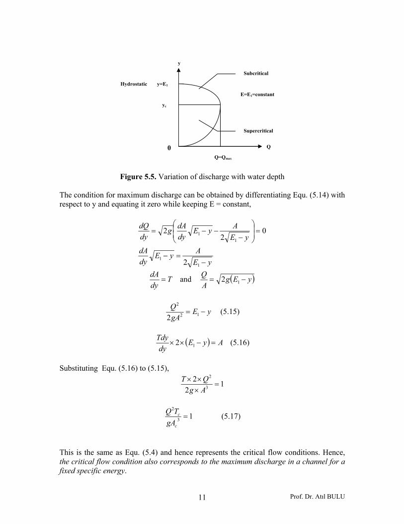
Figure 5.5. Variation of discharge with water depth The condition for maximum discharge can be obtained by differentiating Equ. (5.14) with respect to y and equating it zero while keeping E = constant,
yEAyE
dydA
yEAyE
dydAg
dydQ
−=−
=⎟⎟⎠
⎞⎜⎜⎝
⎛
−−−=
11
11
2
02
2
TdydA
= and ( )yEgAQ
−= 12
yEgAQ
−= 12
2
2 (5.15)
( ) AyEdy
Tdy=−×× 12 (5.16)
Substituting Equ. (5.16) to (5.15),
12
23
2
=×××AgQT
13
2
=c
c
gATQ (5.17)
This is the same as Equ. (5.4) and hence represents the critical flow conditions. Hence, the critical flow condition also corresponds to the maximum discharge in a channel for a fixed specific energy.
Q
Q=Qmax
E=E1=constant
y
y=E1Hydrostatic
yc
0
Subcritical
Supercritical
Prof. Dr. Atıl BULU 12
Rectangular Cross-Section For a given specific energy E = E1,
2
2
22
2
1 22 cc gyqy
ygBQyE +=+=
cc yEygq −××= 12
Taking derivative with respect to y,
11
11
11
32
23
02
2
02
2
EyyE
yyEyE
g
yEyyEg
dydq
cc
cc
c
cc
=→=
=⎟⎠⎞
⎜⎝⎛ −−
−
=⎟⎟⎠
⎞⎜⎜⎝
⎛
−−−=
(5.18)
Maximum discharge for the critical water depth is,
22
232
2
max
max
1
cc
ccc
cc
yygq
yyygq
yEygq
××=
−××=
−××=
( )gByQ
ygq
c
c
5.1max
23max
=
×= (5.19)
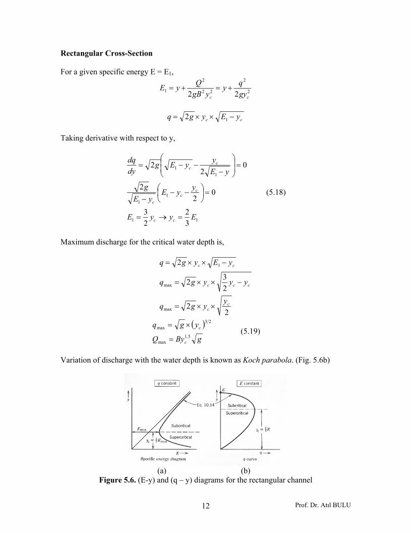
Variation of discharge with the water depth is known as Koch parabola. (Fig. 5.6b)
(a) (b)
Figure 5.6. (E-y) and (q – y) diagrams for the rectangular channel
Prof. Dr. Atıl BULU 13
Example 5.6: Find the critical water depth for a specific energy head of E1 = 1.5 m in the following channels:
a) Rectangular channel, B = 2.0 m. b) Triangular channel, m = 1.5. c) Trapezoidal channel, B = 2.0 m and m = 1.0.
Solution:
a) Rectangular channel
my
myE
c
cc
00.13
250.1
50.123
=×
=
==
b) Triangular channel
my
myE
c
cc
20.125.150.1
50.125.1
==
==
c) Trapezoidal channel
( )( )c
ccc
c
ccc
c
c
cc
ccc
yyyy
TAyE
TA
gQ
gAQy
gVyE
20.220.250.1
2
2232
2
22
++
+=
+=→=
+=+=
By trail and error, yc = 1.10 m. 5.4. Occurrence of Critical Depth The analysis of open channel flow problems usually begins with prediction of points in the channel at which the critical depth yc will occur. Those points feature a change from subcritical to supercritical flow, are known as controls since their occurrence governs, or controls, the liquid depths in the reach of channel upstream from these points. The most obvious place where critical depth can be expected is in the situation in Fig. (5.7), where a long channel of mild slope (S0 < Sc) is connected to a long channel of steep slope (S0 > Sc). At the upstream of the channel, uniform subcritical flow at normal depth,

Prof. Dr. Atıl BULU 14
y01, will occur, and at the downstream a uniform supercritical flow at a smaller normal depth, y02, can be expected. These two uniform flows will be connected by a reach of varied flow in which at some point the depth must pass through the critical water depth, yc. (Chapter 6……).
Figure 5.7 When a long channel of steep slope discharges into one of mild slope (Fig. 5.8), normal depths will occur upstream and downstream from the point of slope change. Under these conditions a hydraulic jump will form whose location will be dictated by the details of slopes, roughness, channel shapes, but the critical depth will be found within the hydraulic jump.
Figure 5.8 The occurrence of critical depth on overflow structures may be proved by examining the flow over the top of a broad-crested weir equipped with a movable sluice gate at the downstream end and discharging from a large reservoir of constant surface elevation. (Fig. 5.9). With a gate closed (position A), the depth of water on the crest will be yA, and the discharge will be zero, giving point A on the q-curve. With the gate raised to position B, a discharge qB will occur, with a decrease in depth from yA to yB. This process will continue until the gate is lifted clear of the flow (C ) and can therefore no longer affect it. With the energy line fixed in position at the reservoir surface level and, therefore, giving constant specific energy, it follows that points A, B, and C have outlined the upper portion of the q-curve, that the flow occurring without gates is maximum, and the depth on the crest is the critical depth. For flow over weirs, a relation between head and discharge may be obtained by substituting yc = 2H/3 (Equ. 5.8) in Equ. (5.7), which yields,
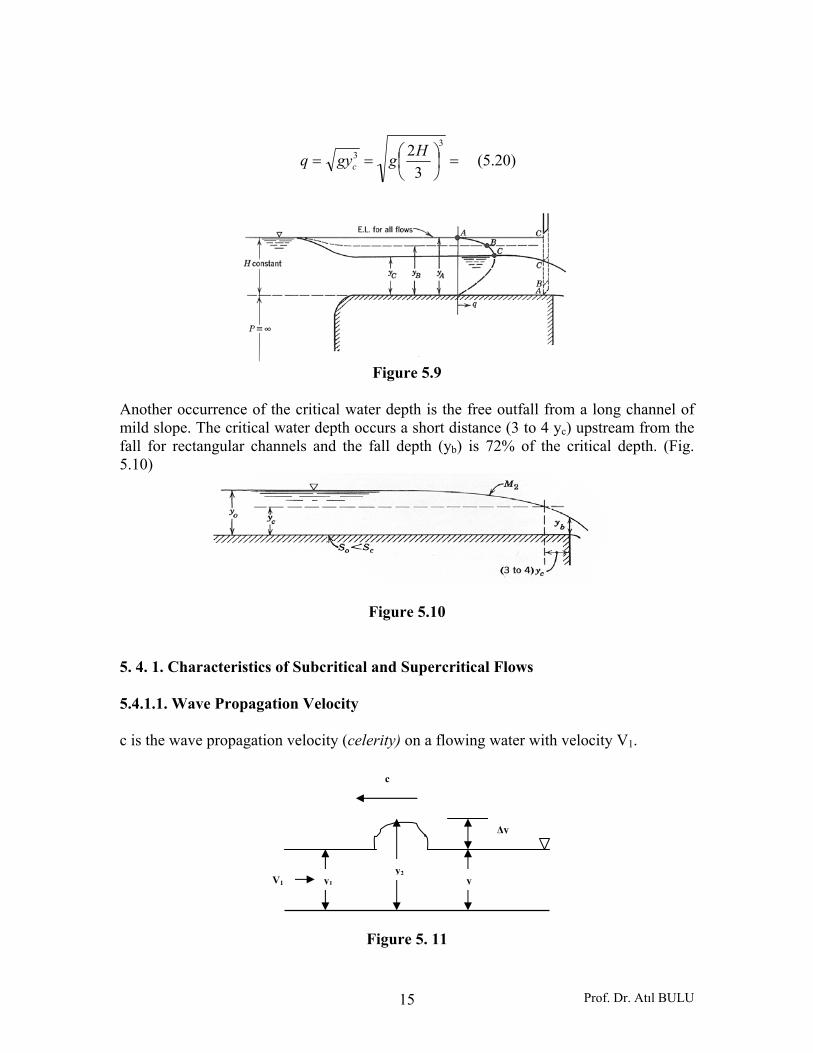
Prof. Dr. Atıl BULU 15
=⎟⎠⎞
⎜⎝⎛==
33
32Hggyq c (5.20)
Figure 5.9
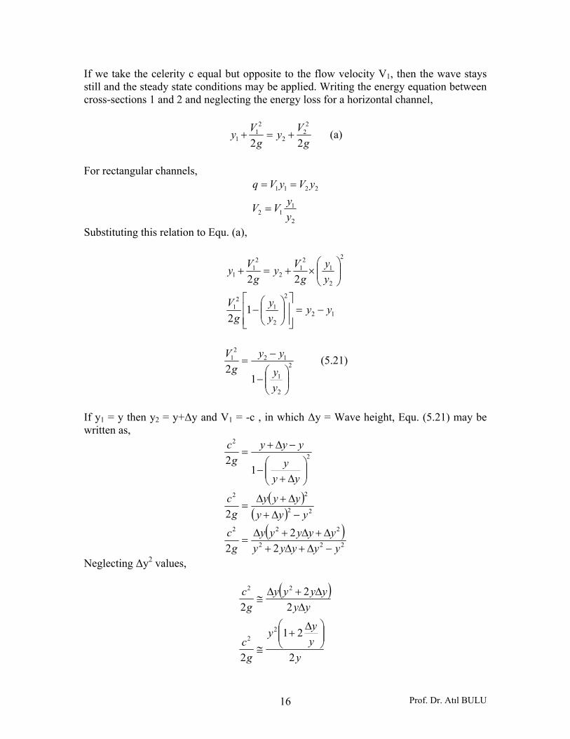
Another occurrence of the critical water depth is the free outfall from a long channel of mild slope. The critical water depth occurs a short distance (3 to 4 yc) upstream from the fall for rectangular channels and the fall depth (yb) is 72% of the critical depth. (Fig. 5.10)
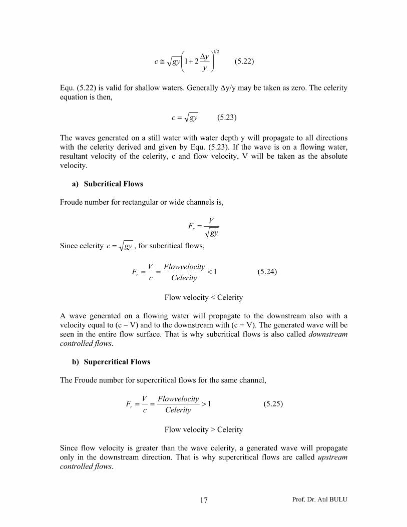
Figure 5.10 5. 4. 1. Characteristics of Subcritical and Supercritical Flows 5.4.1.1. Wave Propagation Velocity c is the wave propagation velocity (celerity) on a flowing water with velocity V1.
Figure 5. 11
y1
y2
Δy
y
c
V1
Prof. Dr. Atıl BULU 16
If we take the celerity c equal but opposite to the flow velocity V1, then the wave stays still and the steady state conditions may be applied. Writing the energy equation between cross-sections 1 and 2 and neglecting the energy loss for a horizontal channel,
gVy
gVy
22
22
2
21
1 +=+ (a)
For rectangular channels,
2
112
2211
yyVV
yVyVq
=
==
Substituting this relation to Equ. (a),
12
2
2
12
1
2
2
12
12
21
1
12
22
yyyy
gV
yy
gVy
gVy
−=⎥⎥⎦
⎤
⎢⎢⎣
⎡⎟⎟⎠
⎞⎜⎜⎝
⎛−
⎟⎟⎠
⎞⎜⎜⎝
⎛×+=+
2
2
1
122
1
12
⎟⎟⎠
⎞⎜⎜⎝
⎛−
−=
yy
yyg
V (5.21)
If y1 = y then y2 = y+Δy and V1 = -c , in which Δy = Wave height, Equ. (5.21) may be written as,
( )( )
( )222
222
22
22
2
2
22
2
2
12
yyyyyyyyyy
gc
yyyyyy
gc
yyy
yyyg
c
−Δ+Δ+Δ+Δ+Δ
=
−Δ+Δ+Δ
=
⎟⎟⎠
⎞⎜⎜⎝
⎛Δ+
−
−Δ+=
Neglecting Δy2 values,
( )
yyyy
gc
yyyyyy
gc
2
21
2
22
2
22
22
⎟⎟⎠
⎞⎜⎜⎝
⎛ Δ+
≅
ΔΔ+Δ
≅
Prof. Dr. Atıl BULU 17
21
21 ⎟⎟⎠
⎞⎜⎜⎝
⎛ Δ+≅
yygyc (5.22)
Equ. (5.22) is valid for shallow waters. Generally Δy/y may be taken as zero. The celerity equation is then,
gyc = (5.23)
The waves generated on a still water with water depth y will propagate to all directions with the celerity derived and given by Equ. (5.23). If the wave is on a flowing water, resultant velocity of the celerity, c and flow velocity, V will be taken as the absolute velocity.
a) Subcritical Flows Froude number for rectangular or wide channels is,
gyVFr =
Since celerity gyc = , for subcritical flows,
1<==Celerity
tyFlowvelocicVFr (5.24)
Flow velocity < Celerity
A wave generated on a flowing water will propagate to the downstream also with a velocity equal to (c – V) and to the downstream with (c + V). The generated wave will be seen in the entire flow surface. That is why subcritical flows is also called downstream controlled flows.
b) Supercritical Flows The Froude number for supercritical flows for the same channel,
1>==Celerity
tyFlowvelocicVFr (5.25)
Flow velocity > Celerity
Since flow velocity is greater than the wave celerity, a generated wave will propagate only in the downstream direction. That is why supercritical flows are called upstream controlled flows.
Prof. Dr. Atıl BULU 18
Case study: Generating waves by throwing a stone to flowing water may be used to know if the flow is subcritical or supercritical for practical purposes. If the generated waves propagate only in the downstream direction, then the flow is supercritical otherwise it is subcritical. 5.5. Transitions The concepts of specific energy and critical energy are useful in the analysis of transition problems. Transitions in rectangular channels are presented here. The principles are equally applicable to channels of any shape and other types of transitions. 5.5.1. Channel with a Hump
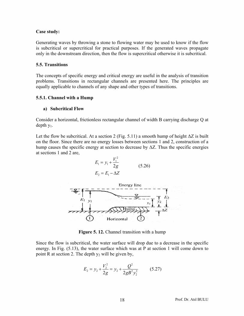
a) Subcritical Flow Consider a horizontal, frictionless rectangular channel of width B carrying discharge Q at depth y1. Let the flow be subcritical. At a section 2 (Fig. 5.11) a smooth hump of height ΔZ is built on the floor. Since there are no energy losses between sections 1 and 2, construction of a hump causes the specific energy at section to decrease by ΔZ. Thus the specific energies at sections 1 and 2 are,
ZEEg
VyE
Δ−=
+=
12
21
11 2 (5.26)
Figure 5. 12. Channel transition with a hump Since the flow is subcritical, the water surface will drop due to a decrease in the specific energy. In Fig. (5.13), the water surface which was at P at section 1 will come down to point R at section 2. The depth y2 will be given by,
22
2
2
2
22
22 22 ygBQy
gVyE +=+= (5.27)
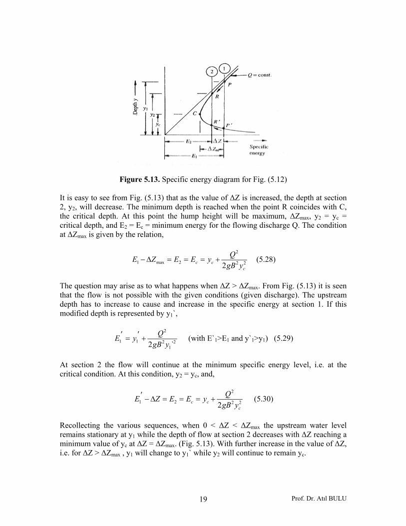
Prof. Dr. Atıl BULU 19
Figure 5.13. Specific energy diagram for Fig. (5.12) It is easy to see from Fig. (5.13) that as the value of ΔZ is increased, the depth at section 2, y2, will decrease. The minimum depth is reached when the point R coincides with C, the critical depth. At this point the hump height will be maximum, ΔZmax, y2 = yc = critical depth, and E2 = Ec = minimum energy for the flowing discharge Q. The condition at ΔZmax is given by the relation,
22
2
2max1 2 ccc ygB
QyEEZE +===Δ− (5.28)
The question may arise as to what happens when ΔZ > ΔZmax. From Fig. (5.13) it is seen that the flow is not possible with the given conditions (given discharge). The upstream depth has to increase to cause and increase in the specific energy at section 1. If this modified depth is represented by y1`,
21
2
2
11 `2 ygBQyE +′=′ (with E`1>E1 and y`1>y1) (5.29)
At section 2 the flow will continue at the minimum specific energy level, i.e. at the critical condition. At this condition, y2 = yc, and,
22
2
21 2 ccc ygB
QyEEZE +===Δ−′ (5.30)
Recollecting the various sequences, when 0 < ΔZ < ΔZmax the upstream water level remains stationary at y1 while the depth of flow at section 2 decreases with ΔZ reaching a minimum value of yc at ΔZ = ΔZmax. (Fig. 5.13). With further increase in the value of ΔZ, i.e. for ΔZ > ΔZmax , y1 will change to y1` while y2 will continue to remain yc.
Prof. Dr. Atıl BULU 20
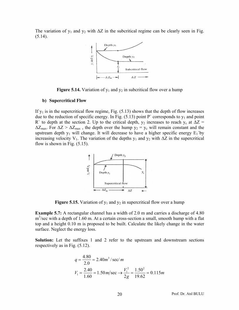
The variation of y1 and y2 with ΔZ in the subcritical regime can be clearly seen in Fig. (5.14).
Figure 5.14. Variation of y1 and y2 in subcritical flow over a hump
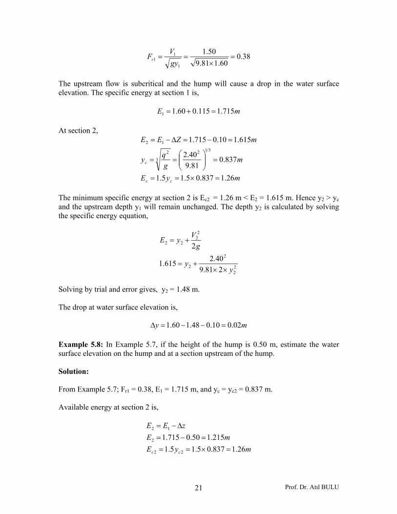
b) Supercritical Flow If y1 is in the supercritical flow regime, Fig. (5.13) shows that the depth of flow increases due to the reduction of specific energy. In Fig. (5.13) point P` corresponds to y1 and point R` to depth at the section 2. Up to the critical depth, y2 increases to reach yc at ΔZ = ΔZmax. For ΔZ > ΔZmax , the depth over the hump y2 = yc will remain constant and the upstream depth y1 will change. It will decrease to have a higher specific energy E1`by increasing velocity V1. The variation of the depths y1 and y2 with ΔZ in the supercritical flow is shown in Fig. (5.15).
Figure 5.15. Variation of y1 and y2 in supercritical flow over a hump Example 5.7: A rectangular channel has a width of 2.0 m and carries a discharge of 4.80 m3/sec with a depth of 1.60 m. At a certain cross-section a small, smooth hump with a flat top and a height 0.10 m is proposed to be built. Calculate the likely change in the water surface. Neglect the energy loss. Solution: Let the suffixes 1 and 2 refer to the upstream and downstream sections respectively as in Fig. (5.12).
mg
VmV
mmq
115.062.19
50.12
sec50.160.140.2
sec//40.20.2
80.4
221
1
3
==→==
==
Prof. Dr. Atıl BULU 21
38.060.181.9
50.1
1
11 =
×==
gyVFr
The upstream flow is subcritical and the hump will cause a drop in the water surface elevation. The specific energy at section 1 is,
mE 715.1115.060.11 =+=
At section 2,
myE
mgqy
mZEE
cc
c
26.1837.05.15.1
837.081.9
40.2
615.110.0715.1312
3
2
12
=×==
=⎟⎟⎠
⎞⎜⎜⎝
⎛==
=−=Δ−=
The minimum specific energy at section 2 is Ec2 = 1.26 m < E2 = 1.615 m. Hence y2 > yc and the upstream depth y1 will remain unchanged. The depth y2 is calculated by solving the specific energy equation,
22
2
2
22
22
281.940.2615.1
2
yy
gVyE
××+=
+=
Solving by trial and error gives, y2 = 1.48 m. The drop at water surface elevation is,
my 02.010.048.160.1 =−−=Δ
Example 5.8: In Example 5.7, if the height of the hump is 0.50 m, estimate the water surface elevation on the hump and at a section upstream of the hump. Solution: From Example 5.7; Fr1 = 0.38, E1 = 1.715 m, and yc = yc2 = 0.837 m. Available energy at section 2 is,
myEmE
zEE
cc 26.1837.05.15.1215.150.0715.1
22
2
12
=×===−=
Δ−=
Prof. Dr. Atıl BULU 22
The minimum specific energy required at section 2 is greater than E2, (Ec2 = 1.26 m > E2 =1.215 m), the available specific energy at that section. Hence, the depth at section 2 will be at the critical depth. Thus E2 = Ec2 = 1.26 m. The upstream depth y1 will increase to a depth y1’ such that the new specific energy at the upstream section 1 is,
76.1294.0
76.162.19
40.2
76.150.026.12
2
21
1
21
2
1
21
2
1
2
21
1
21
=′
+′
=′×
+′
=+=′
+′
Δ+=′
+′
Δ+=′
yy
yy
myg
qy
ZEg
Vy
ZEE
c
c
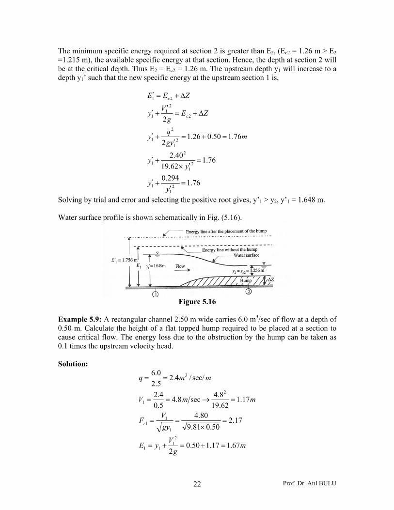
Solving by trial and error and selecting the positive root gives, y’1 > y2, y’1 = 1.648 m. Water surface profile is shown schematically in Fig. (5.16).
Figure 5.16
Example 5.9: A rectangular channel 2.50 m wide carries 6.0 m3/sec of flow at a depth of 0.50 m. Calculate the height of a flat topped hump required to be placed at a section to cause critical flow. The energy loss due to the obstruction by the hump can be taken as 0.1 times the upstream velocity head. Solution:
mg
VyE
gyVF
mmV
mmq
r
67.117.150.02
17.250.081.9
80.4
17.162.198.4sec8.4
5.04.2
sec//4.25.20.6
21
11
1
11
2
1
3
=+=+=
=×
==
=→==
==
Prof. Dr. Atıl BULU 23
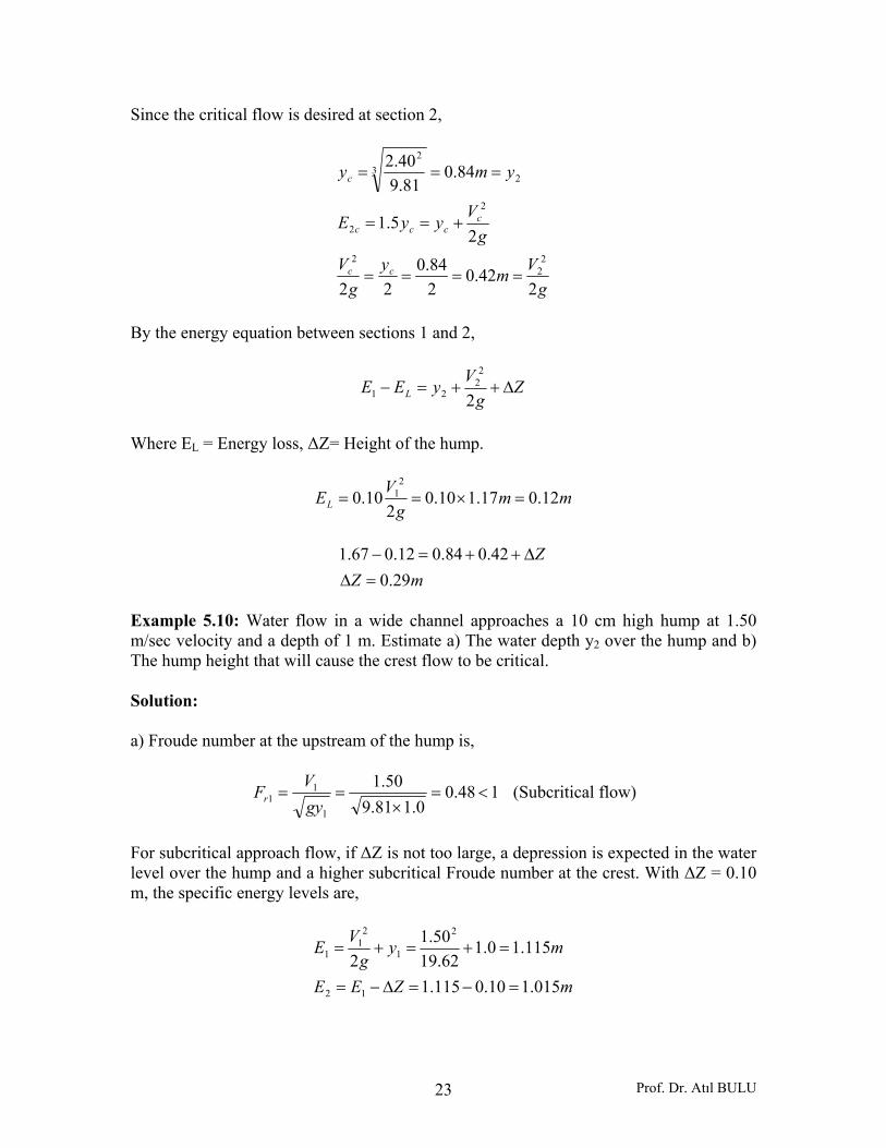
Since the critical flow is desired at section 2,
gVmy
gV
gVyyE
ymy
cc
cccc
c
242.0
284.0
22
25.1
84.081.9
40.2
22
2
2
2
23
2
====
+==
===
By the energy equation between sections 1 and 2,
Zg
VyEE L Δ++=−2
22
21
Where EL = Energy loss, ΔZ= Height of the hump.
mmg
VEL 12.017.110.02
10.02
1 =×==
mZZ
29.042.084.012.067.1
=ΔΔ++=−
Example 5.10: Water flow in a wide channel approaches a 10 cm high hump at 1.50 m/sec velocity and a depth of 1 m. Estimate a) The water depth y2 over the hump and b) The hump height that will cause the crest flow to be critical. Solution: a) Froude number at the upstream of the hump is,
148.00.181.9
50.1
1
11 <=
×==
gyVFr (Subcritical flow)
For subcritical approach flow, if ΔZ is not too large, a depression is expected in the water level over the hump and a higher subcritical Froude number at the crest. With ΔZ = 0.10 m, the specific energy levels are,
mZEE
myg
VE
015.110.0115.1
115.10.162.19
50.12
12
2
1
21
1
=−=Δ−=
=+=+=
Prof. Dr. Atıl BULU 24
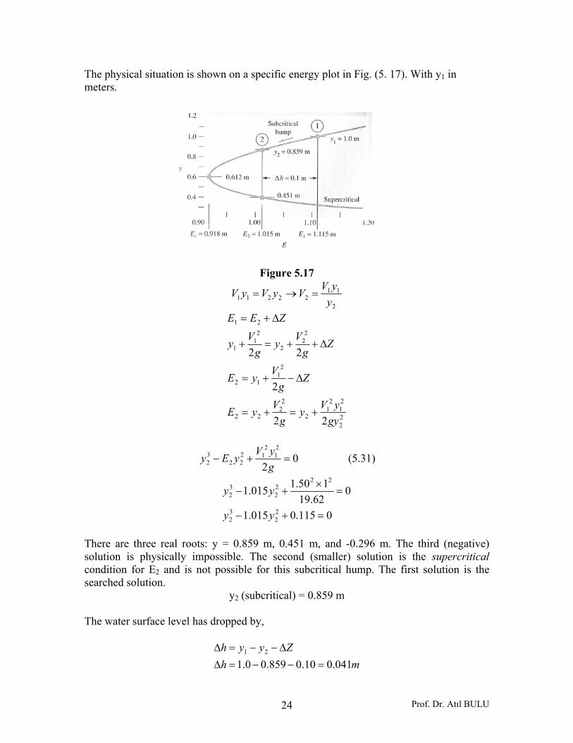
The physical situation is shown on a specific energy plot in Fig. (5. 17). With y1 in meters.
Figure 5.17
2
1122211 y
yVVyVyV =→=
22
21
21
2
22
22
21
12
22
2
21
1
21
22
2
22
gyyVy
gVyE
Zg
VyE
Zg
Vyg
Vy
ZEE
+=+=
Δ−+=
Δ++=+
Δ+=
02
21
212
2232 =+−
gyVyEy (5.31)
0115.0015.1
062.19
150.1015.1
22
32
2222
32
=+−
=×
+−
yy
yy
There are three real roots: y = 0.859 m, 0.451 m, and -0.296 m. The third (negative) solution is physically impossible. The second (smaller) solution is the supercritical condition for E2 and is not possible for this subcritical hump. The first solution is the searched solution.
y2 (subcritical) = 0.859 m
The water surface level has dropped by,
mhZyyh
041.010.0859.00.121
=−−=ΔΔ−−=Δ
Prof. Dr. Atıl BULU 25
60.0859.081.9
75.1
sec75.1859.0
0.150.1
2
22
2
112
=×
==
=×
==
gyVF
myyVV
r
Downstream flow over hump is subcritical. These flow conditions are shown in Fig. (5.17).
b) For critical flow in a wide channel ,
sec5.115.1 2mVyq =×==
mE
gqyEE
c
cc
918.081.95.1
23
23
23
312
312
min,2
=⎟⎟⎠
⎞⎜⎜⎝
⎛×=
⎟⎟⎠
⎞⎜⎜⎝
⎛×===
Therefore the maximum height for frictionless flow over this hump is,
mEEZ 197.0918.0115.1min,21max =−=−=Δ
0.1612.081.9
45.2
sec45.2612.05.1612.0
2
22
=×
=
==→==
r
c
F
mVmyy
For this hump, the surface level at the critical flow has dropped by,
mhZyyh
191.0197.0612.00.1max21
=−−=ΔΔ−−=Δ
5.5.2. Transition with a Change in Width 5.5.2.1. Subcritical Flow in a Width Constriction Consider a frictionless horizontal channel of width B1 carrying a discharge Q at a depth y1 as in Fig. (5.17). At a section 2 channel width has been constricted to B2 by a smooth transition. Since there are no losses involved and since the bed elevations at sections 1 and 2 are the same, the specific energy at section is equal to the specific energy at section 2.
Prof. Dr. Atıl BULU 26
22
22
2
2
22
22
21
21
2
1
21
11
22
22
ygBQy
gVyE
ygBQy
gVyE
+=+=
+=+=
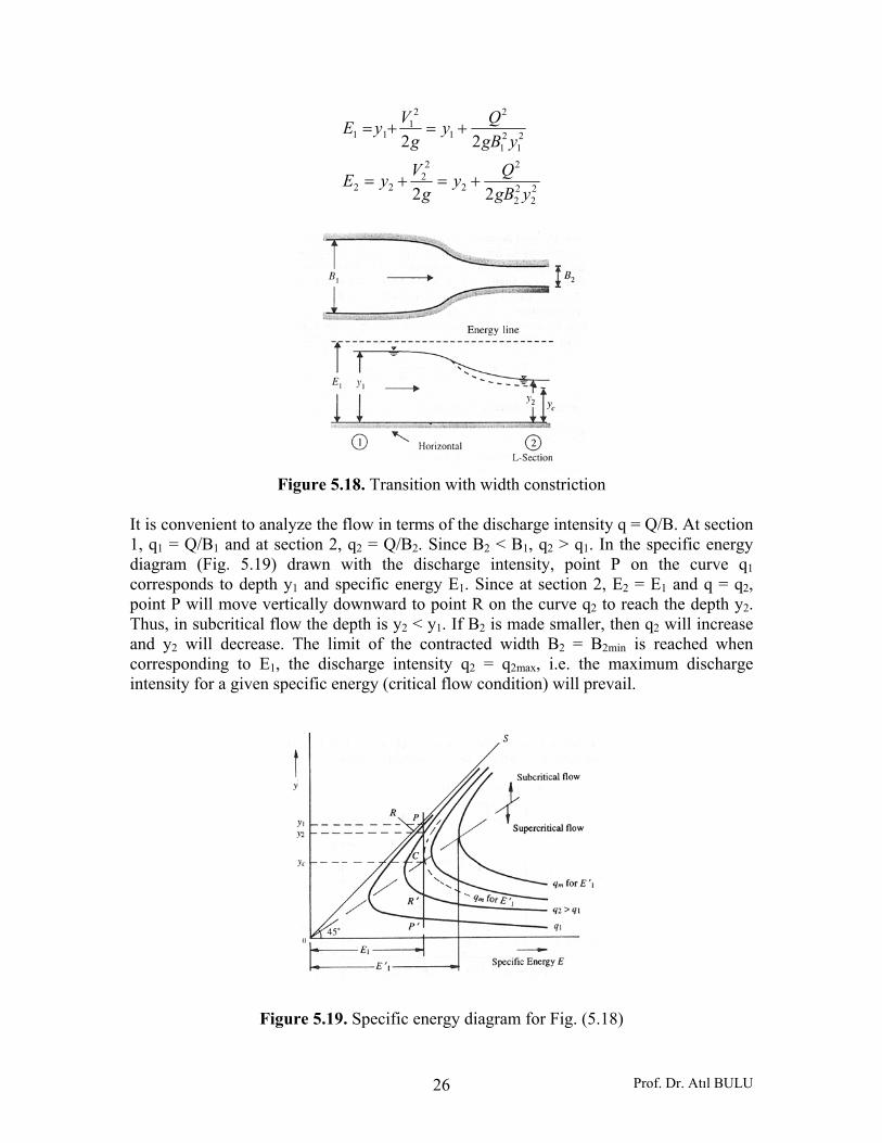
Figure 5.18. Transition with width constriction
It is convenient to analyze the flow in terms of the discharge intensity q = Q/B. At section 1, q1 = Q/B1 and at section 2, q2 = Q/B2. Since B2 < B1, q2 > q1. In the specific energy diagram (Fig. 5.19) drawn with the discharge intensity, point P on the curve q1 corresponds to depth y1 and specific energy E1. Since at section 2, E2 = E1 and q = q2, point P will move vertically downward to point R on the curve q2 to reach the depth y2. Thus, in subcritical flow the depth is y2 < y1. If B2 is made smaller, then q2 will increase and y2 will decrease. The limit of the contracted width B2 = B2min is reached when corresponding to E1, the discharge intensity q2 = q2max, i.e. the maximum discharge intensity for a given specific energy (critical flow condition) will prevail.
Figure 5.19. Specific energy diagram for Fig. (5.18)
Prof. Dr. Atıl BULU 27
At the minimum width, y2 = ycm = critical depth. (5.32)
For a rectangular channel, at critical flow, Cc Ey32
=
Since E1 = ECmin,
1min2 32
32 EEyy CCm === (5.33)
3
2
min2
31
2min2
2
cmc gy
QBgB
Qy =→⎟⎟⎠
⎞⎜⎜⎝
⎛=
3
1
2
min2 23
⎟⎟⎠
⎞⎜⎜⎝
⎛×=
EgQB
31
2
min2 827
gEQB = (5.34)
If B2 < B2min, the discharge intensity q2 will be larger than qmax, the maximum discharge intensity consistent E1. The flow will not, therefore, be possible with the given upstream conditions. The upstream depth will have to increase to y1`. The new specific energy will
( )21
21
2
11 2 yBgQyE
′+′=′
be formed which will be sufficient to cause critical flow at section 2. It may be noted that the new critical depth at section 2 for a rectangular channel is,
2
22
22
31
2
31
22
2
2
5.12 c
ccc
c
yg
VyE
gq
gBQy
=+=
⎟⎟⎠
⎞⎜⎜⎝
⎛=⎟⎟
⎠
⎞⎜⎜⎝
⎛=
Since B2 < B2min , yc2 will be larger that ycm, yc2 > ycm. Thus even though critical flow prevails for all B2 < B2min , the depth section 2 is not constant as in the hump case but increases as y1` and hence E1` rises. The variation of y1, y2 and E with B2/B1 is shown schematically in Fig. (5.20).
( ) 22min2
2
min1 2 cmcmC yBg
QyEE +==
Prof. Dr. Atıl BULU 28
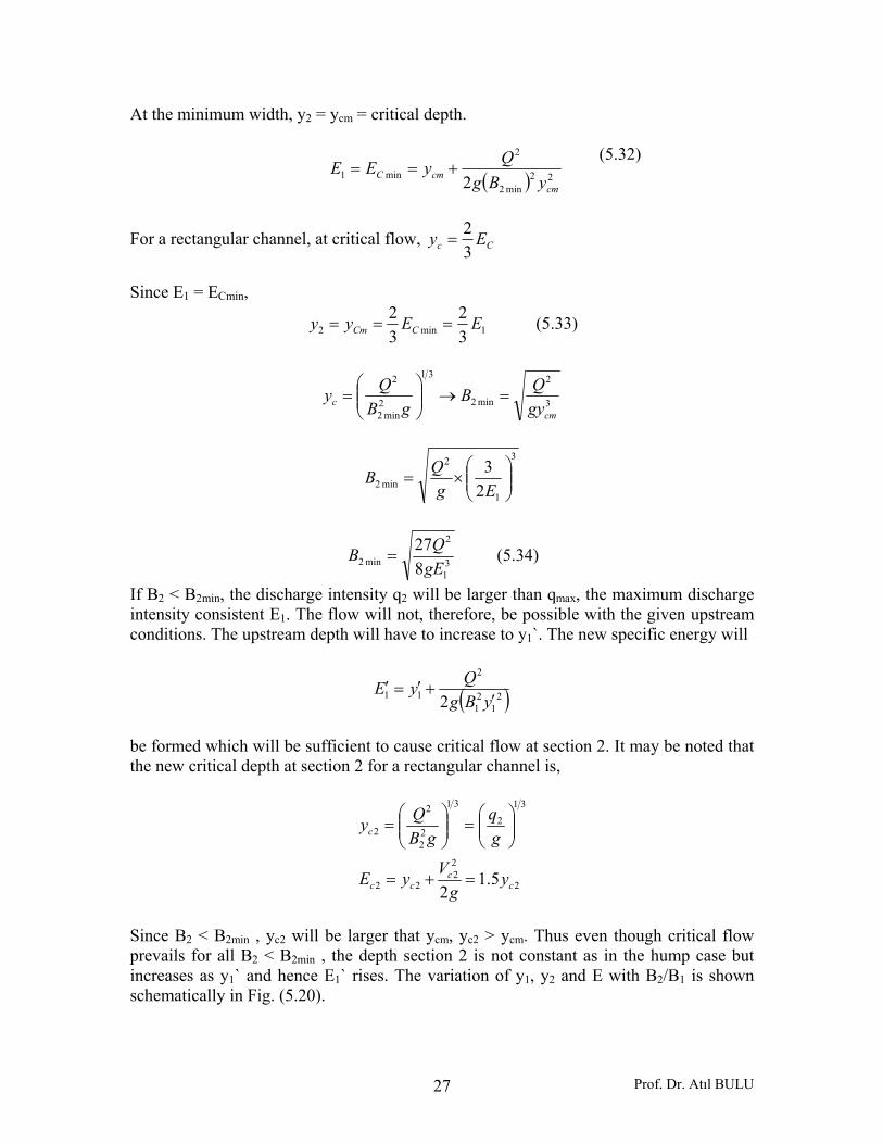
Figure 5.20. Variation of y1 and y2 in subcritical flow in a width constriction
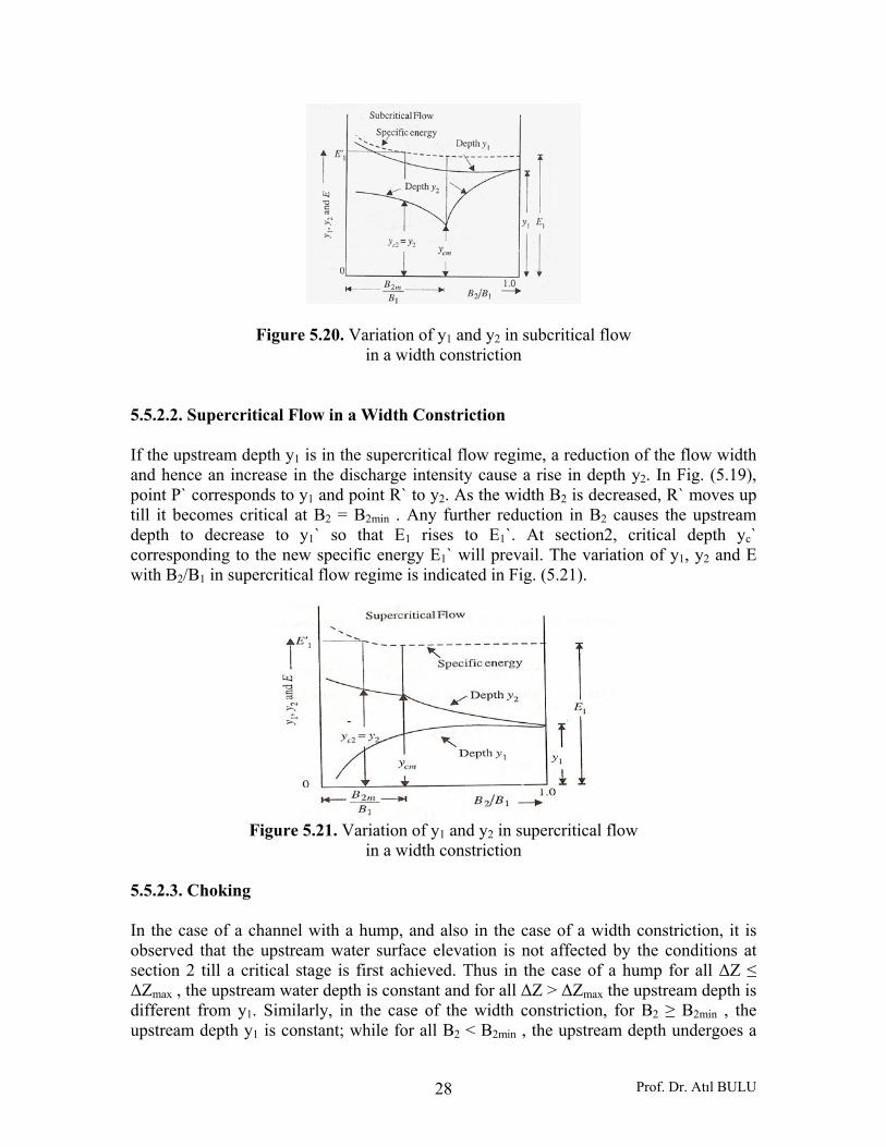
5.5.2.2. Supercritical Flow in a Width Constriction If the upstream depth y1 is in the supercritical flow regime, a reduction of the flow width and hence an increase in the discharge intensity cause a rise in depth y2. In Fig. (5.19), point P` corresponds to y1 and point R` to y2. As the width B2 is decreased, R` moves up till it becomes critical at B2 = B2min . Any further reduction in B2 causes the upstream depth to decrease to y1` so that E1 rises to E1`. At section2, critical depth yc` corresponding to the new specific energy E1` will prevail. The variation of y1, y2 and E with B2/B1 in supercritical flow regime is indicated in Fig. (5.21).
Figure 5.21. Variation of y1 and y2 in supercritical flow
in a width constriction 5.5.2.3. Choking In the case of a channel with a hump, and also in the case of a width constriction, it is observed that the upstream water surface elevation is not affected by the conditions at section 2 till a critical stage is first achieved. Thus in the case of a hump for all ΔZ ≤ ΔZmax , the upstream water depth is constant and for all ΔZ > ΔZmax the upstream depth is different from y1. Similarly, in the case of the width constriction, for B2 ≥ B2min , the upstream depth y1 is constant; while for all B2 < B2min , the upstream depth undergoes a
Prof. Dr. Atıl BULU 29
change. This onset of critical condition at section 2 is a prerequisite to choking. Thus all cases with ΔZ > ΔZmax or B2 < B2min are known as choked conditions. Obviously, choked conditions are undesirable and need to be watched in the design of culverts and other surface drainage features involving channel transitions. Example 5.10: A rectangular channel is 3.50 m wide conveys a discharge of 15.0 m3/sec at a depth of 2.0 m. It is proposed to reduce the width of the channel at a hydraulic structure. Assuming the transition to be horizontal and the flow to be frictionless determine the water surface elevations upstream and downstream of the constriction when the constricted width is a) 2.50 m and b) 2.20 m. Solution: Let suffixes 1 and 2 denote sections upstream and downstream of the transition respectively.
48.00.281.9
14.2
sec14.20.25.3
0.15
1
11
111
111
=×
==
=×
==
=
gyVF
myB
QV
yVBQ
r
The upstream flow is subcritical and the transition will cause a drop in the water surface.
mg
VyE 23.262.19
14.20.22
221
11 =+=+=
Let B2min = minimum width at section 2 which does not cause choking.
mEy
mEE
cc
c
49.123.232
32
23.2
min
1min
=×==
==
mB
gyQB
gBQy
cc
63.249.181.9
0.155.0
3
2
min2
5.0
3
2
min22min2
23
=⎟⎟⎠
⎞⎜⎜⎝
⎛×
=
⎟⎟⎠
⎞⎜⎜⎝
⎛=→=
Prof. Dr. Atıl BULU 30
a) When B2 = 2.50 m B2 = 2.50 m < B2min = 2.63 m and hence choking conditions prevail. The depth at section 2 = y2 = yc2. The upstream depth y1 will increase to y1`.
myE
mgqy
mq
cc
c
31.254.15.15.1
54.181.90.6
sec65.20.15
22
3123122
2
22
=×==
=⎟⎟⎠
⎞⎜⎜⎝
⎛=⎟⎟
⎠
⎞⎜⎜⎝
⎛=
==
At the upstream section 1:
21
1
21
2
1
21
21
1
21
11
2
11
21
938.031.2
81.9229.431.2
22
sec29.450.30.1531.2
yy
yy
ygqy
gVyE
mBQq
mEE c
′+′=
′××+′=
′+′=
′+′=′
===
==′
Solving by trial and error and selecting positive subcritical flow depth root,
my 10.21 =′
b) When B2 = 2.20 m; As B2 < B2min choking conditions prevail. Depth at section 2 = y2 = yc2.
myE
my
mmq
cc
c
52.268.15.15.1
68.181.982.6
82.620.20.15
22
312
2
22
=×==
=⎟⎟⎠
⎞⎜⎜⎝
⎛=
==
At upstream section 1, new upstream depth = y1`,
Prof. Dr. Atıl BULU 31
52.2938.0
52.22
sec29.4
52.2
21
1
21
21
1
21
21
=′
+′
=′
+′
=
==′
yy
ygqy
mq
mEE c
Solving by trial and error, the appropriate depth to give subcritical flow is,
my 35.21 =′
[Note that for the same discharge when B2 < B2min (i.e. under choking conditions) the depth at the critical section will be different from yc = 1.49 m and depends on the value B2]. 5.5.2.4. General Transition A transition in general form may have a change of channel shape, provision of a hump or a depression, contraction or expansion of channel width, in any combination. In addition, there may be various degrees of loss of energy at various components. However, the basic dependence of the depths of flow on the channel geometry and specific energy of flow will remain the same. Many complicated transition situations can be analyzed by using the principles of specific energy and critical depth. In subcritical flow transitions the emphasis is essentially to provide smooth and gradual changes in the boundary to prevent flow separation and consequent energy losses. The transitions in supercritical flow are different and involve suppression of shock waves related disturbances. Example 5.12: A discharge of 16.0 m3/sec flows with a depth of 2.0 m in a rectangular channel 4.0 m wide. At a downstream section the width is reduced to 3.50 m and the channel bed is raised by ΔZ. Analyze the water surface elevations in the transitions when a) ΔZ = 0.20 m and b) ΔZ = 0.35 m. Solution: Let the suffixes 1 and 2 refer to the upstream and downstream sections respectively. At the upstream section,
45.00.281.9
0.2
sec0.224
16
1
11
1
=×
==
=×
=
gyVF
mV
r
Prof. Dr. Atıl BULU 32
The upstream flow is subcritical and the transition will cause a drop in the water surface elevation.
mg
VyE
mg
V
20.220.00.22
20.062.190.2
22
111
221
=+=+=
==
For the transition cross-section 2,
myE
mgqy
mBQq
cc
c
94.129.123
23
29.181.9
57.4
sec57.450.30.16
22
3123122
2
2
22
=×==
=⎟⎟⎠
⎞⎜⎜⎝
⎛=⎟⎟
⎠
⎞⎜⎜⎝
⎛=
===
c) When ΔZ = 0.20 m,
E2 = Available specific energy at section 2
mEmZEE c 94.100.220.020.2 212 =>=−=Δ−=
Hence the depth y2 > yc2 and the upstream depth will remain unchanged at section 1, y1.
my
y
EZg
Vy
00.220.020.262.1957.4
2
22
2
2
1
22
2
=−=×
+
=Δ++
my
y 00.2064.122
2 =+
Solving by trial and error,
my 58.12 =
Hence when ΔZ = 0.20 m, y1 = 2.00 m and y2 = 1.58 m. The drop in water surface is,
mh 22.020.058.100.2 =−−=Δ
Prof. Dr. Atıl BULU 33
c) When ΔZ = 0.35 m,
E2 = Available specific energy at section 2
mEmE c 94.185.135.020.2 22 =<=−=
Hence the contraction will be working under the choked conditions. The upstream depth must rise to create a higher to energy. The depth of flow at section 2 will be critical with,
y2 = yc2 = 1.29 m
If the new depth is y1’,
my
y
yy
ZEygB
Qy c
29.2815.0
35.094.10.462.190.16
2
21
1
21
2
2
1
221
21
2
1
=′
+′
+=′××
+′
Δ+=′
+′
By trial and error,
my 10.21 =′
The upstream depth will therefore rise by 0.10 m due to the choked condition at the constriction. Hence, when ΔZ = 0.35 m,
y1’ = 2.10 m and y2 = yc2 = 1.29 m
Prof. Dr. Atıl BULU
Hydraulic Jump
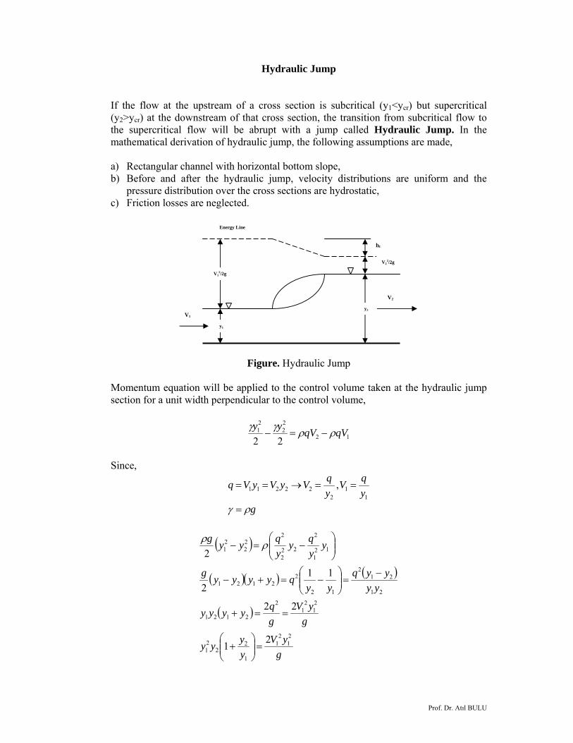
If the flow at the upstream of a cross section is subcritical (y1<ycr) but supercritical (y2>ycr) at the downstream of that cross section, the transition from subcritical flow to the supercritical flow will be abrupt with a jump called Hydraulic Jump. In the mathematical derivation of hydraulic jump, the following assumptions are made, a) Rectangular channel with horizontal bottom slope, b) Before and after the hydraulic jump, velocity distributions are uniform and the
pressure distribution over the cross sections are hydrostatic, c) Friction losses are neglected.
Figure. Hydraulic Jump
Momentum equation will be applied to the control volume taken at the hydraulic jump section for a unit width perpendicular to the control volume,
12
22
21
22qVqVyy ρργγ
−=−
Since,
gyqV
yqVyVyVq
ργ =
==→==1
12
22211 ,
( )
( )( ) ( )
( )
gyV
yyyy
gyV
gqyyyy
yyyyq
yyqyyyyg
yyqy
yqyyg
21
21
1
22
21
21
21
2
2121
21
212
12
22121
121
2
222
222
21
21
22
112
2
=⎟⎟⎠
⎞⎜⎜⎝
⎛+
==+
−=⎟⎟
⎠
⎞⎜⎜⎝
⎛−=+−
⎟⎟⎠
⎞⎜⎜⎝
⎛−=− ρρ
V12/2g
y1
V1 y2
V2
V22/2g
hL
Energy Line
Prof. Dr. Atıl BULU
Multiplying both side of the above equation with (1/y1
3) yields,
⎟⎟⎠
⎞⎜⎜⎝
⎛×⎥⎦
⎤⎢⎣
⎡=⎟⎟
⎠
⎞⎜⎜⎝
⎛+ 3
1
21
21
1
22
21
121yg
yVyyyy
1
21
1
2
1
2 21gyV
yy
yy
=⎟⎟⎠
⎞⎜⎜⎝
⎛+ (1)
Since for rectangular channels,
gyVFr =
Equation (1) takes the form of,
02 21
1
2
2
1
2 =−+⎟⎟⎠
⎞⎜⎜⎝
⎛Fr
yy
yy
Solution of this equation and taking the positive sign of the square root gives,
( )18121 2
1
21−+= rF
yy (2)
The ratio of flow depths after and before the hydraulic jump (y2/y1) is a function of the Froude number of the subcritical flow before hydraulic jump.
Hydraulic Jump as an Energy Dissipater If we write the difference of the specific energies before after the hydraulic jump,
( ) ⎟⎟⎠
⎞⎜⎜⎝
⎛−+−=Δ
⎟⎟⎠
⎞⎜⎜⎝
⎛+−⎟⎟
⎠
⎞⎜⎜⎝
⎛+=−=Δ
gV
gVyyE
gVy
gVyEEE
22
222
22
121
22
2
21
121
Prof. Dr. Atıl BULU
Since,
22
11 ,
yqV
yqVVyq ==→=
( ) ⎟⎟⎠
⎞⎜⎜⎝
⎛−+−=Δ 2
221
2
2111
2 yygqyyE (3)
It has been derived that,
( )gqyyyy
2
21212
=+
( )2121
2
41
2yyyy
gq
+=
Putting this equation to Equation (3),
( ) ( )
( ) ( ) ( )
( ) ( ) ( )
( ) ( )[ ]
( )( )21
21212
21
2212112
21
122
212121
21
122
2121
22
21
21
22
212121
4
44
44
41
)(41
yyyyyyE
yyyyyyyyE
yyyyyyyyyyE
yyyyyyyyE
yyyyyyyyyyyE
−−=Δ
++−−=Δ
−++−=Δ
−++−=Δ
−++−=Δ
The analytical equation of the energy dissipated with the hydraulic jump is,
( )21
312
4 yyyyE −
=Δ (4)
The power lost by hydraulic jump can be calculated by,
EQN w Δ= γ
Where, γw = Specific weight of water = 9.81 kN/m3 Q = Discharge (m3/sec) ΔE = Energy dissipated as head (m) N = Power dissipated (kW)

Prof. Dr. Atıl BULU
Some empirical equations were given to calculate the length of hydraulic as,
L = 5.2y2 Safranez equation
L = 5(y2 – y1) Bakhmetef equation
L = 6(y2 – y1) Smetana equation
L = 5.6y2 Page equation
Physical explanation of Equations (2) and (4) gives that,
a) If 0111
21 =Δ→=→= E
yyFr (critical flow)
b) If 011
21 >Δ>→→> E
yyFr (hydraulic jump)
c) If 0111
21 <Δ→<→< E
yyFr (Energy gain is not possible. Transition from
supercritical to subcritical flow is with gradual water surface profile) Physical Explanation of Critical Flow It has been derived that,
( )212122 yyygyq += (5)
Since for rectangular channels,
32
3
2
cr
cr
gyq
gqy
=
=
Equation (5) can be written as,
( )212132 yyyyycr +=
If multiply both sides with ⎟⎟⎠
⎞⎜⎜⎝
⎛3
1
cry,
crcr yyy
yyy 2
212212 += (6)

Prof. Dr. Atıl BULU
Defining as,
crcr yyY
yyY 2
21
1 , ==
Equation (6) takes the form of,
022
2122
1 =−+ YYYY
The curve of this equation,
The physical explanation of this curve gives, For,
crcr yyyyYY
<→><→>
12
12 11
and
crcr yyyyYY
>→<>→<
12
12 11
The regimes of the flows should be different when passing through a critical flow depth. If the flow is subcritical at downstream when passing through critical water depth it should be in supercritical at the downstream and vice versa. Example: If the Froude number at the drop of a hydraulic jump pool is 6 and the water depth is 0.50 m, find out the length of the hydraulic jump. Calculate the power dissipated with the hydraulic jump if the discharge on the spillway is 1600 m3/sec.
Y1=y1/yc
Y2=y2/yc
1
1
Prof. Dr. Atıl BULU
Solution: Using the equation of the ratio of water depths,
( )( )
myyyy
Fryy
485.08
8168121
18121
12
2
1
2
21
1
2
=×=×=
=−×+=
−+=
The length of hydraulic jump by different equations,
myL 8.2042.52.5 2 =×=×= (Safranez)
( ) ( ) myyL 5.175.0455 12 =−×=−= (Bakhmetef)
( ) ( ) myyL 215.0466 12 =−×=−= (Smetana)
myL 4.2246.56.5 2 =×=×= (Page)
It is preferred to be on the safe side with the hydraulic structures. Therefore, the longest result will be chosen. The length of the hydraulic jump will be taken as L = 22.4 m for design purposes.
Energy dissipated as head,
( )
( ) mE
yyyyE
36.545.04
5.04
43
21
312
=××
−=Δ
−=Δ
The power dissipated with the hydraulic jump,
kWNN
EQN w
8413136.5160081.9
=××=
Δ= γ