chapter 5 trail signing - wilderness.net 5 trail signing modified on 7/14/05 5.1 introduction this...
TRANSCRIPT

5-1
Chapter 5 Trail Signing
Modified on 7/14/05
5.1 Introduction
This chapter provides standards and guidelines for the use of signs and posterson National Forest System Trails (NFSTs).
Chapter 5A contains typical sign placement and installation information forcommon trail situations.
Chapter 5B contains standard drawings for common trail signs.
Use trail signage to support the objectives of providing opportunities forexperiencing nature while engaging in outdoor recreation in an improved,aesthetic atmosphere that is consistent with policy (FSH 2309.18) and forestplan direction.
Select and use trail signs, posters, and markers to provide the following on aconsistent basis:
• Route identification (number, name, or both)• Guidance and distance to trail destinations and key points of interest• Safety features such as snow shelters and resorts• Route reassurance and confirmation• User safety: warnings of known hazards• Notice of restrictions where use control is necessary• Protection of resources
Additional locations and conditions for which signing may be needed include thefollowing:
• Trail termini• Junctions with other trails and roads• Administrative boundaries• Special management areas• Lakes, streams, and other features identified on maps, trail guides, or at
the trailhead• Interpretive opportunities
Additional information on trail signage is located at:Trail Matrix - http://www.fs.fed.us/r3/measures/Inventory/Trails.htm
5.1.1 ROS Guidelines
A key element for developing and managing a trail sign program is theRecreation Opportunity Spectrum (ROS). ROS classes or similar managementguidelines have been adopted for each forest plan management area.
ROS offers a framework for understanding the relationships of signing and othermanagement actions in various settings to the kinds of experiences visitorshave. For example, hiking in a large, undeveloped area with difficult access andfew signs designed to provide only limited information enhances the hiker’sfeelings of self-reliance with respect to orienteering skills, self-discovery,challenge, and solitude. In contrast, walking easy interpretive trails outside avisitor center with numerous signs and information offers the visitor morecomfort, security, opportunities for learning, and social opportunities.
Use trail signage to
support the objectives
of providing
opportunities for
experiencing nature
while engaging in
outdoor recreation...

5-2
Chapter 5 Trail Signing
Modified on 7/14/05
ROS guidelines may be found athttp://www.fs.fed.us/recreation/programs/beig/beig6c.htm
Table 5-1 contains specific ROS information for trail signs.
In addition to the ROS, consider the following in determining the proper sign,size, material, placement, and mounting requirements for trail signage:
• Managed uses for the trail• Scenic integrity objectives• Travel speed• Viewing distance • Clear-zone requirements (Chapter 3A)• Nighttime visibility needs
Table 5-1—Recreation Opportunity Spectrum selection guide for materials, colors, and finishes for trailsigns, markers, and supports
SemiprimitiveItem Primitive Nonmotorized Motorized Roaded, natural Rural/urban
1. Sign materials Solid wood (or Solid wood (or Solid wood, Wood, natural Wood, metal,appearing so) appearing so) plywood, fiberglass, fiberglass,
limited use limited use syntheticsof synthetics of syntheticsand metal and metal
Color or finish Natural or Natural or Natural, stained, Stained or Painted, stainedstained; stained; or painted painted etched or decalspreservative preservativenot evident not evident Retroreflective Retroreflective Retroreflective
2. Sign support Tree or rustic Tree or rustic Post or tree; Wood, metal or Wood, metal ormaterials post post limited use other synthetic other synthetic
of synthetics post post
Color or finish Natural or Natural or Natural, stained, Stained or Painted, stainedstained; stained; or painted; painted anodized, etc.preservative preservative preservativenot evident not evident may be evident
3. Reassurance Cut/painted Cut/painted Cut/painted or Cut/painted or Painted metal ormarkers blazes; routed blazes; routed synthetic blazes; synthetic blazes; synthetic
and scorched, and scorched, routed and wood, metal, andor branded or branded scorched; or synthetic markerssolid wood (or solid wood (or branded wood;appearing so); appearing so); wood guidelimited use of limited use of poles or rocksynthetics synthetics cairnswhen a national when a nationalstandard; wood standard; woodguide poles or guide poles orrock cairns rock cairns Retroreflective Retroreflective Retroreflective

5.1.2 Accessibility
Where trails managed for hikers have been evaluated for accessibility, post thefollowing in addition to the standard message with the trail identity anddestinations at the beginning of the trail:
• Typical and maximum trail grade • Typical and maximum tread cross slope• Minimum clear tread width• Tread surface type and firmness• Any major height obstacles (as appropriate)
Forest Service accessibility guidelines, including the Forest Service TrailsAccessibility Guidelines and the Forest Service Outdoor Recreation AccessibilityGuidelines, can be viewed at:
http://www.fs.fed.us/recreation/programs/accessibility/
5.1.3 Access and Travel Management
Consider the travel management direction for the trail system. Travelmanagement is crucial to help guide and manage visitors from the time they firstenter the forest, to the time they reach their destinations and then return to thepoint of entry. Use appropriate guide signs for the traffic that is encouraged (thatis, the actively managed uses of the trail). To the extent possible, accomplishtravel management regulation through trail atlas use maps and/or travelmanagement signs at trail termini and junctions. Refer to Chapter 6 forinformation on access and travel management signage.
5.1.4 Sign Planning
Follow direction in Chapter 2 for developing, monitoring, and maintaining acomprehensive sign plan for each trail or trail complex. Include all signing in traildesign and/or rehabilitation planning. Monitor signing effectiveness throughvisitor contacts and observation of compliance. Provide the minimum signsnecessary to adequately and properly guide the user.
5.1.4a Recreational Studies, Engineering Studies, and EngineeringJudgment
Recreation plans or studies should be used to determine appropriate signing fornonmotorized and nonmechanized trail systems and for guide signs on all trails.
Recreation studies or reviews should be used to determine appropriate warningand regulatory signs and traffic control devices for motorized trails andbicycle/mountain bike trails when use is entirely on NFSTs.
Engineering studies or engineering judgment should be used to determineappropriate warning and regulatory signs and traffic control devices formotorized trails and bicycle/mountain bike trails when use is on NationalForest System Roads (NFSRs).
Coincident routes that involve NFSRs and NFSTs shall follow the Manual onUniform Traffic Control Devices (MUTCD) and Forest Service standards forroads.
Refer to Section 3.8 for information on engineering judgments and engineeringstudies.
5-3
Chapter 5 Trail Signing
Modified on 7/14/05

5.1.5 Coincident Routes
A coincident route is defined as a single route that is managed as part of twodifferent inventoried routes in the Forest Transportation Atlas. An example is aNFSR that is also a NFST. There are two types of coincident routes:
1. Concurrent coincident route: A coincident route on which the uses aresimultaneous and must be managed for mixed traffic.
2. Separate coincident route: A coincident route on which the uses are notsimultaneous but separate, so the route is not managed for mixed traffic.Separate use periods may occur by: • Specific times, such as weekday and weekend. • Seasons, such as a summer road and a winter snow trail.
Decisions to manage and sign coincident routes involving NFSRs must bebased on engineering judgment or an engineering study. Routes shall be signedbefore concurrent use occurs. Refer to Section 3A.7.3 for information on propersigning of coincident routes involving NFSRs.
Coordinate the signing of coincident routes (road and trail or trail and trail) toavoid confusion between types of users.
Where nonconcurrent seasonal or specific time use is allowed or designated onsystem roads closed to standard highway vehicles, follow the appropriate trailstandards. Remove, fold up, or cover any road signs that are inappropriate ordistracting to the trail user. When the roads are open to highway vehicular trafficand closed to the trail traffic, signing shall meet MUTCD and Forest Servicestandards for roads. Remove, fold up, or cover any trail signs that areinappropriate or distracting to the general driving public. Generally, trailreassurance markers may be left in place.
When use is concurrent (that is, the road is open to highway vehicular trafficand trail traffic at the same time), signing shall meet MUTCD and Forest Servicestandards for roads. Signs should be appropriate for both user groups. If signed,destinations should be reachable by the road and trail traffic.
Where bicycle use occurs in conjunction with a road or where the bicycle trail ispaved, follow the guidelines in the MUTCD, Chapter 9.
For coincident nonmotorized terra trails and snow trails with nonconcurrentseasonal or specific time use, do not seasonally change the snow trailreassurance blazers to the gray/white summer blazers unless necessary foradded visual contrast with dark summer backgrounds.
5.1.6 Requirements for Retroreflection
Signs for roads, motorized trails, urban cross-country ski trails, paved bicycletrails, and mountain bike trails as well as other signs intended to be seen atnight shall be retroreflective to show the same shape, color, and message byboth day and night.
5-4
Chapter 5 Trail Signing
Modified on 7/14/05

5.1.7 Sign Sizes
Signs should be sized according to the viewing distance and the normal rate oftravel or the desired speed of the trail vehicle.
For nonmotorized hiker/pedestrian and pack and saddle trails, 1-inch letters areadequate for most viewing situations.
For motorized and other trail systems such as bicycles, determine appropriatesign sizes through recreational studies or reviews.
For motorized, bicycle, and cross-country ski trails, see Table 5-2 forrecommended minimum sizes for signs.
Letter size for interpretative, safety, and other informational signs or posters isdependent upon the distance from which the message is to be viewed. SeeChapter 10A for additional information.
5.1.8 Adopt-a-Trail Signs
Adopt-a-Trail signs may be used as needed to recognize cooperators’ help withtrails.
5.2 Regulatory and Warning Signs
For on-trail signing needs, use standard regulatory and warning sign messages,shapes, and colors as found in the MUTCD and Chapter 3A. Nonstandardmessage signs shall be approved by the Washington Office Director ofEngineering. Table 5-3 gives specific trail regulatory and warning signinformation for the different types of trails.
5.2.1 Regulatory Signs
Provide regulatory information at the trailhead if possible. Stress educationapproaches over restrictions. Compose regulatory sign messages that minimizeprohibitory language. Use a courteous tone and explain restrictions in terms ofeasily understood resource or user benefits with which the public can relate.
Limit use of on-trail regulatory signs and posters to the minimum needed inorder to:
• Ensure consistent protection of the trail and adjacent resources.• Provide for the safety and enjoyment of the user.• Provide for enforcement of regulations.
The traffic management strategies of “discourage” and “eliminate” may bepreferable to the use of regulations in some cases.
Place regulatory signs at the point of regulation.
Larger signs may be used for increased visibility or strong emphasis when needhas been determined.
5-5
Chapter 5 Trail Signing
Modified on 7/14/05
Table 5-2—Minimum sign sizes for motorized, bicycle, and cross-country ski trails
Minimum letter Minimum size Minimum sizesize (inches) recreation symbol (inches) warning sign (inches)
2 12 12 x 12
Adopt-a-Trail
HIGH DESERTFOUR WHEELERS

5.2.2 Warning Signs and Markers
Consistent with the management plan for the trail or area, use warning signs toalert users of known hazards that, relative to the ROS setting, are unusual,unexpected, or not readily apparent to the typical visitor under conditions whenuse normally occurs. Consider changing trail grade, alignment, or location ortaking other measures to mitigate the hazard before using a warning sign. Donot use warning signs and markers in wilderness.
Use adequate advance placement distances for warning signs to allow time forsafe user response.
When a need has been determined, use standard object markers according tothe following direction and to guidance in Chapter 3 to identify obstructionswithin or adjacent to the trail:
• Type II object markers are used to mark collision hazards adjacent to the trail,such as drop-offs or culvert ends that coincide with abrupt alignment changesor that are obscured by vegetation.
• Type III object markers are used to mark collision hazards within the trailway,such as bridge railings or abutments narrower than the travel way.
5-6
Chapter 5 Trail Signing
Modified on 7/14/05
Table 5-3—Regulatory and warning sign requirements
Minimum size Shape or Trail type Sign face (inches) Color sign type
Hiker/pedestrian Retroreflective not Warning: 12 x 12 If used, follow If used, follow pack and saddle required; use for MUTCD colors MUTCD shapes
added emphasis
Wilderness Never Regulatory: limited NA NAretroreflective use at trailhead
Warning: do not use NA NA
Cross-country ski, Shall be Warning: 12 x 12 Shall follow Shall follow urban setting or night retroreflective MUTCD colors MUTCD shapesskiing
Cross-country ski, Retroreflective not Warning: 12 x 12 If used, follow If used, follow semi-primitive required; use for MUTCD colors MUTCD shapesmotorized and added emphasisnonmotorized ROS
Bicycle, Shall be Shall follow MUTCD Shall follow Shall follow paved or coincident retroreflective Table 9B-1 MUTCD colors MUTCD shapeswith roads
Mountain bike Shall be Warning: 12 x 12 Shall follow Shall follow retroreflective MUTCD colors MUTCD shapes
ATV/motorcycle Shall be Warning: 12 x 12 Shall follow Shall follow retroreflective MUTCD colors MUTCD shapes
Snowmobile Shall be Warning: 12 x 12 Shall follow Shall follow retroreflective MUTCD colors MUTCD shapes
Water Shall be Warning: 12 x 12 Shall follow Shall follow retroreflective MUTCD colors MUTCD shapes

5.3 Guide Signs
Use guide signs to identify the trail and its directions and for guidance todestinations.
Signs shall be located either at the junction or in advance of the junction suchthat trail junctions are evident.
Three types of guide signs are used on NFSTs (see Figure 5-1).
5.3.1 Signing Rules for Guide Signs
5.3.1a Nonwilderness Trails
1. Route identification (required)
• Route identification (trail name, number, or both) and the trail direction(s)are required for all system trail legs at all NFST junctions. - Example: Great Ridge Tr. No. 458 #.- Exception: Do not identify trail legs on which traffic is discouraged,
prohibited, or against one-way traffic flow. • Use only names and numbers that appear on the most current Forest
Service trail maps.• Include national trail designations as appropriate. • The trail route identification and its direction(s) should always be signed
first and then followed by the destinations associated with that trail.
2. Destinations
• Required trail destinations - Exit signing: At a minimum, show the direction and distance to the
trailhead or trail access point at the first junction from the trailhead oraccess point.
• Optional trail destinations- Facilities such as trailheads, campgrounds, picnic areas, winter shelters,
rental cabins, and other key points of interest- Major geographic or natural features such as lakes, major rivers and
streams, passes, falls, and meadows- Administrative structures such as guard stations
5-7
Chapter 5 Trail Signing
Modified on 7/14/05
8 B I G C R E E K T R . N O . 1 4 7
P I P E R S C A M P
H I E R O G L Y P H I C S S P R I N G S
T O N T O R I M T R . N O . 1 6 9
J CT. V E R D E R I V E R R O A DP H O E N I X T R . N O . 9 1J C T . P H O E N I X R O A D 7
MOUNTA I N V I EW TR . NO . 2MOUNTA I N V I EW TRHD . 5
MOOSE MEADOWS TR . NO . 4
TD TDW FRD
Figure 5-1—Trail directional signs.
Nonmotorized, primitive andwilderness use (routed)
Wilderness use (optional) (routed) Motorized, bicycle and cross-country ski use (retroreflective)
• Sign only those destinations that can be readily accessed by the intendedtrail user.
• If a destination has been identified on a guide sign, identify it on allsubsequent guide signs along the trail until the destination is reached.
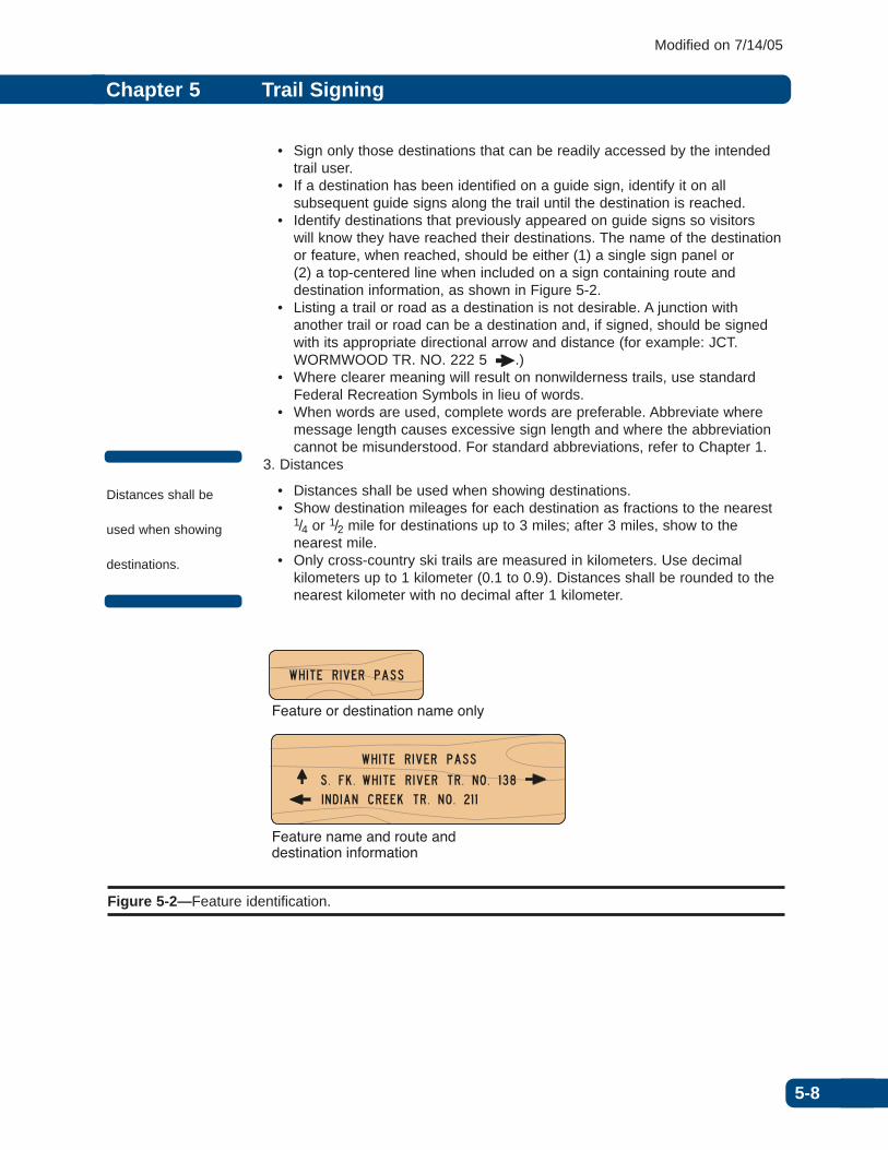
• Identify destinations that previously appeared on guide signs so visitors will know they have reached their destinations. The name of the destinationor feature, when reached, should be either (1) a single sign panel or (2) a top-centered line when included on a sign containing route anddestination information, as shown in Figure 5-2.
• Listing a trail or road as a destination is not desirable. A junction withanother trail or road can be a destination and, if signed, should be signedwith its appropriate directional arrow and distance (for example: JCT.WORMWOOD TR. NO. 222 5 #.)
• Where clearer meaning will result on nonwilderness trails, use standardFederal Recreation Symbols in lieu of words.
• When words are used, complete words are preferable. Abbreviate wheremessage length causes excessive sign length and where the abbreviationcannot be misunderstood. For standard abbreviations, refer to Chapter 1.
3. Distances
• Distances shall be used when showing destinations.• Show destination mileages for each destination as fractions to the nearest
1/4 or 1/2 mile for destinations up to 3 miles; after 3 miles, show to thenearest mile.
• Only cross-country ski trails are measured in kilometers. Use decimalkilometers up to 1 kilometer (0.1 to 0.9). Distances shall be rounded to thenearest kilometer with no decimal after 1 kilometer.
5-8
Chapter 5 Trail Signing
Modified on 7/14/05
W H I T E R I V E R P A S S
S . F K . W H I T E R I V E R T R . N O . 1 3 8I N D I A N C R E E K T R . N O . 2 1 1
W H I T E R I V E R P A S S
Feature or destination name only
Feature name and route and destination information
Figure 5-2—Feature identification.
Distances shall be
used when showing
destinations.

5.3.1b Wilderness Trails
Use signs within wilderness and primitive areas only when necessary to protectthe resource or to provide for visitor safety.
1. Route Identification
• Identify trail legs at all system trail intersections where necessary. Routeidentification may include trail name, number, or both, or locally identifiabledestination. Include appropriate directional arrow(s).
• When consistent with other trail markings, blazes or cairns may be used inlieu of guide signs to indicate trail direction
2. Destinations
• Show direction arrows only. • Required trail destinations
- Exit signing: show the direction to the trailhead or trail access at the firstjunction from the trailhead or access point.
• Prohibited destination signing- Do not sign major destinations at the destination location.- Do not sign geographic or natural features.
• Optional trail destinations- Guide signs may be used to identify appropriate trail destinations. - Administrative structures may have an identification sign.
3. Distances
• Do not provide mileages.
4. Prohibited signs
• Do not use standard Federal Recreation Symbol signs. • Do not use interpretive information or locator signs.
5.3.2 Guide Sign Layout
Limit guide signs to four lines of text for best user comprehension, signreadability, and stability. If more lines are needed, use two sign panels. Do notuse more than five lines of text on a sign.
5.3.2a Arrows
Arrow placement on signs is extremely critical to the functionality of the sign. Asa general rule, directional arrows should be horizontal or vertical, but at irregularintersections, an oblique arrow may convey a clearer indication of the directionto be followed. In some cases, especially trail junctions, combinations of arrowsmay be needed.
5-9
Chapter 5 Trail Signing
Modified on 7/14/05
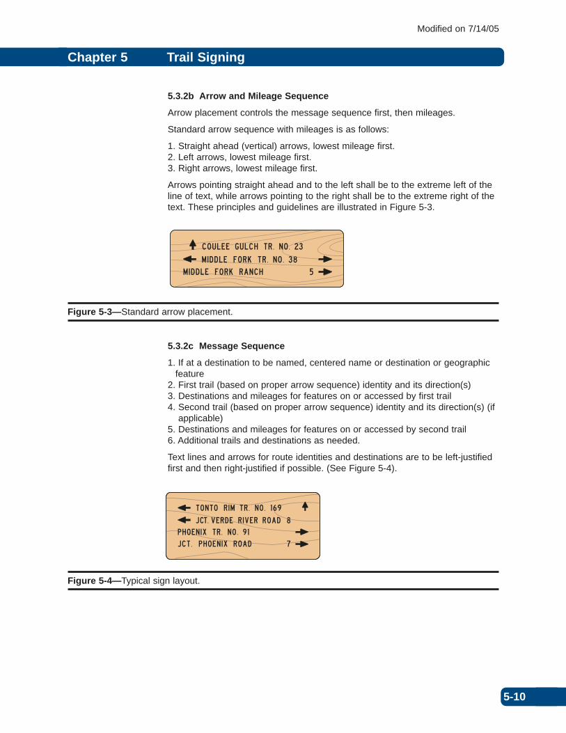
5.3.2b Arrow and Mileage Sequence
Arrow placement controls the message sequence first, then mileages.
Standard arrow sequence with mileages is as follows:
1. Straight ahead (vertical) arrows, lowest mileage first.2. Left arrows, lowest mileage first.3. Right arrows, lowest mileage first.
Arrows pointing straight ahead and to the left shall be to the extreme left of theline of text, while arrows pointing to the right shall be to the extreme right of thetext. These principles and guidelines are illustrated in Figure 5-3.
5.3.2c Message Sequence
1. If at a destination to be named, centered name or destination or geographicfeature
2. First trail (based on proper arrow sequence) identity and its direction(s)3. Destinations and mileages for features on or accessed by first trail4. Second trail (based on proper arrow sequence) identity and its direction(s) (if
applicable)5. Destinations and mileages for features on or accessed by second trail6. Additional trails and destinations as needed.
Text lines and arrows for route identities and destinations are to be left-justifiedfirst and then right-justified if possible. (See Figure 5-4).
5-10
Chapter 5 Trail Signing
Modified on 7/14/05
M I D D L E F O R K T R . N O . 3 8M I D D L E F O R K R A N C H 5
C O U L E E G U L C H T R . N O . 2 3
Figure 5-3—Standard arrow placement.
8
T O N T O R I M T R . N O . 1 6 9
J CT. V E R D E R I V E R R O A DP H O E N I X T R . N O . 9 1J C T . P H O E N I X R O A D 7
Figure 5-4—Typical sign layout.

5.3.2d Special Cases
Trail signs require that the trail route identification and its direction(s) be signedfirst; the destinations associated with that trail are then listed under the trailidentification. L junctions require combinations of arrows that are an exceptionto the standard arrow placement rules.
The sign shown in Figure 5-5 is for a trail that has a right L junction. In order torepresent the trail and the destinations on that trail properly, the destination tothe right must be signed before signing the next trail leg and any destination tothe left.
The sign shown in Figure 5-6 is for a trail that has a left L junction. In order torepresent the trail and the destinations on that trail properly, the vertical arrowmust be placed on the right and, if signing a straight ahead destination, the uparrow will be next under the left arrow in its proper position on the left of the sign.
Figure 5-5—Trail sign with a right L junction.
5-11
Chapter 5 Trail Signing
Modified on 7/14/05
COUL E E TR . NO . 424
M I D D L E FORK TR . NO . 437M I D D L E FORK TRHD .
5
5
COUL E E GULCH
COUL E E TR . NO . 424
M I D D L E FORK TR . NO . 437M I D D L E FORK TRHD .
5
5
COUL E E GULCH
Figure 5-6—Trail sign with a left L junction.

5.3.2e Mileage Layout
Mileage is not to be aligned in the same column as the trail numbers. There arethree options for displaying mileage on signs (Figure 5-7):
1. Mileage for up and leftdirections may be aligned in thesame column with the rightarrows (right justified).
2. All mileage may be placed in asingle column before thearrows on the right.
3. Mileage may be entered withthe text line.
5-12
Chapter 5 Trail Signing
Modified on 7/14/05
COUL E E TR . NO . 424COUL E E GULCHM I D D L E FORK TR . NO . 437M I D D L E FORK TRHD .
8
5
COUL E E TR . NO . 424M I D D L E FORK TR . NO . 437M I D D L E FORK TRHD .
M I D D L E FORK RANCH 55
COUL E E TR . NO . 424M I D D L E FORK TR . NO . 437M I D D L E FORK TRHD .
W FK . RANCH 55
Figure 5-7—Three options for mileage display.

5.4 Sign Specifications
Select the sign material, color, size, and shape that best suit the trail purposeand the ROS class (see Table 5-1) or management prescription for the area.Signs shall conform to the specifications in Chapter 14.
Table 5-4 gives specific trail guide sign information for the different types oftrails. Text requirements are consistent with series established by the AmericanStandards Association (ASA).
5-13
Chapter 5 Trail Signing
Modified on 7/14/05
Table 5-4—Guide sign requirements
Capital ASATrail type Sign face Series C text Color Shape
Hiker/pedestrian Typically routed 1 inch, routed Unfinished wood with scorched TDpack and saddle or blackened legend or WPC material
Wilderness Routed only 1 inch, routed May be unfinished wood with TDscorched or blackened legend or
TDW
Cross-country ski Shall be 2 inches, minimum White legend on brown background FRDurban setting or retroreflectivenight skiing
Cross-country ski May be routed 1 inch, routed May be unfinished wood with TDsemi-primitive scorched or blackened legend ormotorized and WPC materialnonmotorized ROS
Bicycle Shall be 2 inches, minimum White legend on brown background FRDpaved or coincident retroreflectivewith roads
Mountain bike Shall be 2 inches, minimum White legend on brown background FRDretroreflective
ATV/motorcycle Shall be Capital ASA Series C, White legend on brown background FRDretroreflective 2 inches, minimum
Snowmobile Shall be 2 inches, minimum White legend on brown background FRDretroreflective
Water Shall be 2 inches, minimum White legend on brown background FRDretroreflective

5.5 Junction Identity Signs
In a trail system where junctions are designated with numbers or letters, ajunction identity sign may be used. Signs should use the word “JCT” followed bythe number or letter of the junction.
With junction-numbered or junction-lettered systems, it is especially important toensure that trail maps or locator map signs are available either at the trailheador along the trail.
Use junction signs in conjunction with trail guide signs at the trail junction.Mount above or below the guide sign on the same post (see Figure 5-8). Table5-5 gives specific trail junction identity sign information for the different types oftrails.
5-14
Chapter 5 Trail Signing
Modified on 7/14/05
Table 5-5—Junction identity sign requirements
Capital ASATrail type Sign face Series C Text Color Shape
Hiker/pedestrian Typically routed 1 inch, routed Unfinished wood with Rectanglepack and saddle scorched or blackened legend
or WPC material
Wilderness Routed only 1 inch, routed May be unfinished wood, TD orscorched or blackened legend TDW or WPC material
Cross-country ski Shall be 2 inches, minimum White legend on brown FRDurban setting or retroreflective backgroundnight skiing
Cross-country ski May be routed 1 inch, routed May be unfinished wood TDsemi-primitive with scorched or blackened motorized and legend or WPC materialnonmotorized ROS
Bicycle Shall be 3 inches, minimum White legend on brown FRDpaved or coincident retroreflective backgroundwith roads
Mountain bike Shall be 2 inches, minimum White legend on brown FRDretroreflective background
ATV/motorcycle Shall be 2 inches, minimum White legend on brown FRDRetroreflective background
Snowmobile Shall be 2 inches, minimum Black legend on orange 9 in. x12 inretroreflective background diamond
TB-2
White legend on brown FRDbackground
Water Shall be 2 inches, minimum White legend on brown FRDretroreflective background

5.6 Locator Map Signs
Use of self-locator map signs is often appropriate at trail junction to provide anextra measure of orientation and security. At a minimum, the map should clearlydisplay the trail system and the location of the user when at that particular mapwith a “You Are Here” arrow.
Depending on the type of trail system, other information may be needed suchas groomed or ungroomed conditions. See Figure 5-8.
5-15
Chapter 5 Trail Signing
Modified on 7/14/05
J C T
AMOUNTA I N V I EW TR . NO . 2TRA I L H EAD 5
MOOSE MEADOWS TR . NO . 4
YOU A R E H E R E
Figure 5-8—Typical trail guide sign installation.

5.7 Trail and Road Crossings
When trails cross each other or cross roads, there is a potential for accidents.
When roads and trails cross, MUTCD and Forest Service standards shall befollowed. Determine the need for intersection control on the trail and/or the needfor crossing signs on the road by engineering judgment or in an engineeringstudy.
When trails cross each other, determine appropriate signing by a recreationstudy or review. Consider the road or trail characteristics, sight distance,stopping distance, traffic types, volumes, speeds, and applicable state trafficlaws. Refer to Chapter 3A.
Crossing signs shall be located at the best possible sight and stopping distancefor both the road user and the trail user. Signs should be placed 10-15 feet fromthe road shoulder or far enough back to be outside of snow berms when roadsor trails are plowed.
Road crossings and their related signing shall be coordinated with the governingroad agency.
5.7.1 Regulatory and Warning Signs
Advance crossing or crossing warning signs (MUTCD Vehicular Traffic andNonvehicular Signs Series W11) may be used to warn the users driving onroads of trail traffic crossing the road.
Regulatory and warning signs may also be needed on the trail to regulate orcontrol the trail users before they cross the road.
While STOP and YIELD signs are generally not needed where trails cross eachother, evaluate each crossing on a site by site basis.
Refer to Figure 5A-1 for typical placement or regulatory and warning signs onthe road and on the trail.
5.7.2 Guide Signs
Retroreflective road guide signs may be used to identify trail access points wheretrails cross a road or terminate on a road and where trailhead parking facilitieshave not been developed. Use Federal Recreation Symbols as appropriate tomark crossings. Refer to Figure 5A-2 for typical placement of road guide signs.
Install road guide signs only where traffic safety will not be compromised byslowing or stopping vehicles and where there are appropriate turnouts withinsight distance for safe parking. Guide signs shall not be installed where thereare no safe approaches and turnouts.
Refer to Chapter 3C for sizing, placement, and mounting. As a general rule,road signs should be placed before the intersection at a sufficient distance thathas been determined by engineering judgment or study that considers speed,sight distance, traffic volume and type, season of use, and the location of otherpossible conflicting intersections.
5-16
Chapter 5 Trail Signing
Modified on 7/14/05

5.8 Reassurance Markers
Reassurance markers reconfirm the identity, location, or route of the trail. Useappropriate standard route markers, blazers, cairns, or guide poles where neededto reassure travelers that they are on the trail. Do not use where the trail is self-defining under conditions in which use normally occurs, or if excluded under thetrail management plan.
Do not place access and travel management information on reassurance markers.Access and travel management information needs to be displayed separately withsufficient detail to show dates or reasons.
From the following markers, select those that are most appropriate for the trailtype and ROS Class (see Table 5-1):
1. Route markers
A route marker provides the minimum information necessary to reconfirm thetrail identity. It should include the route number or letter, any specific logossuch as National Trail markers, and the appropriate trail blazer. Use ofSimplified Difficulty Level symbols is optional. Do not place agency orcooperator logos on the route marker. See Figure 5-9 for priority of placementof the different symbols on route markers.
Use the minimum number of route markers along the trail, at road crossings,past trail junctions, and at termini as needed to reconfirm the identity of thetrail.
Where vandalism is a problem, it may be advisable to place the route markera short distance along the trail, beyond and out of sight of trail beginnings andcrossings of roads or other trails.
5-17
Chapter 5 Trail Signing
Modified on 7/14/05
Minimum30 inches
Route numberor letter
Trail marker
Blazer
2 2
Figure 5-9—Priority and placement of reassurance markers.

a) Route number or letter
Place the route identification number or letter at the top of post. Thefollowing methods may be used:
• Number or letter routed and scorched, blackened, or branded intowood post or sign
• Number or letter on wood, aluminum, plastic, or fiberglass substrate,screw mounted to wood post
• Number or letter decal affixed to fiberglass post
On metal markers, white numbers or letters on brown background arerecommended.
b) Trail markers
When the trail has a designated logo (such as a National Scenic Trail,National Recreation Trail, or National Historic Trail) place the appropriatemarker beneath the route identification number or letter. Follow ROSguidelines and the management direction established for the trail. Table 5-6gives specific trail marker information for the different types of trails.
5-18
Chapter 5 Trail Signing
Modified on 7/14/05
Table 5-6—Reassurance marker requirements
Trail type Sign face Blazer Color Size (inches)
Hiker/pedestrian NA TB-1 Grey/white 5 x 7pack and saddle Cut/painted/branded Natural
Wilderness NA Cut or branded NaturalDo not use plastic
Cross-country ski Shall be TB-1 Blue 5 x 7urban setting or retroreflectivenight skiing TB-2 with arrow 9 x 12
Cross-country ski May be TB-1 Blue 5 x 7semi-primitive retroreflectivemotorized and TB-2 with arrow 9 x 12nonmotorized ROS
Bicycle Shall be Federal Recreational White legend on brown Minimum 12paved or coincident retroreflective Symbol RL-090 background square incheswith roads
Mountain bike Shall be Federal Recreational White legend on brown Minimum 3retroreflective Symbol RL-090 background square inches
ATV/motorcycle Shall be Federal Recreational White legend on brown Minimum 3retroreflective Symbol RL-150 or RL-170 background square inches
Snowmobile Shall be TB-1 Orange or 5 x 7retroreflective Fluorescent
TB-2 with arrow orange 9 x 12
Water Shall be Federal Recreational White legend on brown Minimum 3retroreflective Symbol RW-020 background square inches
c) Difficulty levels
Difficulty levels are based on a national set of characteristics andstandards, not on a comparison of trials against one another. See FSH2309.18 for policy concerning use and application of difficulty levels.
Use of signage or maps that indicate national trail difficulty standards isnecessary to ensure consistency. Consider site-specific signage or mapinformation that indicates the physical trail standards and maintenanceand/or grooming schedules.
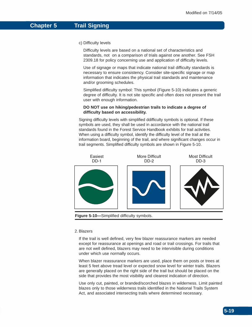
Simplified difficulty symbol: This symbol (Figure 5-10) indicates a genericdegree of difficulty. It is not site specific and often does not present the trailuser with enough information.
DO NOT use on hiking/pedestrian trails to indicate a degree ofdifficulty based on accessibility.
Signing difficulty levels with simplified ddifficulty symbols is optional. If thesesymbols are used, they shall be used in accordance with the national trailstandards found in the Forest Service Handbook exhibits for trail activities.When using a difficulty symbol, identify the difficulty level of the trail at theinformation board, beginning of the trail, and where significant changes occur intrail segments. Simplified difficulty symbols are shown in Figure 5-10.
2. Blazers
If the trail is well defined, very few blazer reassurance markers are neededexcept for reassurance at openings and road or trail crossings. For trails thatare not well defined, blazers may need to be intervisible during conditionsunder which use normally occurs.
When blazer reassurance markers are used, place them on posts or trees atleast 5 feet above tread level or expected snow level for winter trails. Blazersare generally placed on the right side of the trail but should be placed on theside that provides the most visibility and clearest indication of direction.
Use only cut, painted, or branded/scorched blazes in wilderness. Limit paintedblazes only to those wilderness trails identified in the National Trails SystemAct, and associated intersecting trails where determined necessary.
5-19
Chapter 5 Trail Signing
Modified on 7/14/05
EasiestDD-1
More DifficultDD-2
Most DifficultDD-3
Figure 5-10—Simplified difficulty symbols.

a) Colored diamonds
Use the small TB-1 (5 by 7 inches) metal or plastic diamond marker (seeFigure 5-11), retroreflective (for night use) or nonreflective when called forin the trail management plan. Do not use for wilderness trails.
Mount on trees or, where properly positioned trees are not available, onposts. When diamond markers are to be mounted on trees, aluminum nailsshould be used. Leave a portion of the shank exposed to allow for treegrowth.
An arrow may be placed in the center of the TB-2 (9 by 12 inches; seeFigure 5-11) to indicate the trail direction for additional visibility in openareas or to indicate continuing direction or an unusual change in directionthat does not present a hazard. Do not use these markers in lieu of curve,turn, or other warning signs where conditions require a standard warningsign as determined by recreational studies or review or engineering studyor engineering judgment. Use this method sparingly and not in place of astandard blazer.
b) Cut blazes
Use cut blazes when called for in the trail management plan. Cut blazing isthe preferred reassurance marking system in wilderness areas where treesare available. Improper blazes cannot be corrected. Cut blazes carefullyand cleanly to conform closely to the dimensions shown in Figure 5-12.
c) Painted blazes
Use painted blazes on trees or rocks only where specified in the trailmanagement plan. Do not paint without using a template and paintcarefully to specified dimensions and color.
d) Branded or routed and scorched blazes
Either branded blazes or routed and scorched blazes may be used wherespecified in the trail management plan.
Field branding may be used on the face of the guide sign or on a flattenedportion of the tree or post that supports the guide sign.
5-20
Chapter 5 Trail Signing
Modified on 7/14/05
5” x 7” 9” x 12”
TB-2TB-1
Figure 5-11—Colored diamond blazers.

The blaze may also be branded or routed and scorched in a shop on thefollowing:
• The face of the guide sign• A 6- by 10-inch piece of wood the same substrate as the guide sign• The support post for the guide sign
Directional arrows may be branded or routed and scorched below the blazeindicating the direction(s) of the trail.
e) Federal recreational symbols
Minimum 3-inch Federal recreation symbols such as RL-170 or RL-090,may be used as reassurance blazers. Symbols shall be mounted to postssuch as flexible fiberglass. National recreation trail symbols shall not beused as reassurance markers.
5-21
Chapter 5 Trail Signing
Modified on 7/14/05
Blaze trees on both sides
Cut no deeper than necessary for clear visibility.Cut on both sides, visiblefrom both directions.
2 in.4”
2-4 in.
8 in.
Figure 5-12—Cut blazes.

3. Cairns
Rock cairns may be used through rocky, treeless areas as necessary forguidance and safety. Base spacing on visibility conditions expected duringadverse weather.
See Figure 5-13 for typical details. Select and fit rocks for stability againstdisplacement. Construct cairns so they are high enough to appear abovevegetation. Where practicable, set guide poles or posts in cairns whereneeded for winter travel guidance.
4. Guide poles
Guide poles may be used to delineate the trail when the location is not obvious.When used, set poles at the maximum inter-visible distances required forguidance through treeless areas such as meadows and muskeg areas. Selectnatural pole materials to harmonize with the environment except where themanagement plan requires increased visibility (for example, snowmobile andcross-country ski trails). To increase visibility, consider painting the poles (colorto match the color of the plastic blazer), mounting plastic trail blazers on bothsides of the poles, or wrapping retroreflective tape around the pole.
Wooden guide poles shall have a minimum diameter of 4 inches and aminimum height of 6 feet above ground or snow level. Where groundconditions make the setting of wood poles impractical, the use of metal orother materials is justified.
5-22
Chapter 5 Trail Signing
Modified on 7/14/05
Figure 5-13—Rock cairn.
3 feetminimum
30 inchesminimum

5.9 Congressionally Designated Trails
Congressionally designated trail signage must be consistent among administrativeunits. Coordinate area and trail management plans as appropriate. Standardizetrail signing within areas that include more than one administrative unit.
5.9.1 National Trail Systems
National trails “provide for the ever-increasing outdoor recreation needs of anexpanding population and in order to promote the preservation of, public accessto, travel within, and enjoyment and appreciation of the open-air, outdoor areas,and historic resources of the Nation…” (National Trails System Act of 1968).
5.9.1a National Recreation Trails
National recreation trails are designated under Regional Forester authority toprovide for a variety of outdoor recreation uses in or reasonably accessible tourban areas.
5.9.1b National Scenic Trails
National scenic trails are trails designated by Congress to provide for maximumoutdoor recreation potential and for the conservation and enjoyment of thenationally significant scenic, historic, natural, or cultural qualities of the areasthrough which they pass.
5.9.1c National Historic Trails
National historic trails are designated by Congress and follow as closely aspossible and practicable the original trails or routes of travel of national historicsignificance. They identify and protect the historic route and its historic remnantsand artifacts for public use and enjoyment.
5.9.2 National Trail System Signing
Signing of trails in the National Trail System requires special emphasis todenote their uniqueness and special qualities. Identify national scenic, historic,and recreation trails with the appropriate national marker, such as those shownin Figure 5-14. Sign according to the management objective of each trailsystem. The policy and criteria for signing and posting national trails are thesame as for other National Forest System Lands, with the exceptions noted inthe following sections.
Figure 5-14—Examples of national trail markers.
5-23
Chapter 5 Trail Signing
Modified on 7/14/05
®
NA
TIO
NAL
RECREATIO
N TR
AIL

5.9.2.1 Trailheads
At trailheads or developed recreation sites associated with the trail, mount the9-inch national trail marker on the base of the site identification sign or on aseparate post in a prominent location.
5.9.2.2 Road Crossings
To indicate the trail crossing a road, use the 9-inch marker along NFSRs whenspeeds are 35 miles per hour or lower. Use the 18-inch marker on roads whenspeeds are 40 miles per hour and higher. Mount the markers 1 inch below theguide sign identifying the trail or its destinations. If no other identification signexists, the marker should be mounted on a separate post to identify the trail. Itsuse is intended only as a symbol associated with the trail. The words are notintended to be read by motorists at highway speeds.
Larger signs may be produced and used for special situations on high speedhighways. Maintain the same shape and colors when ordering special sizesigns.
5.9.2.3 Guide Signs
When the trail guide sign is located on the national trail, identify the national traildesignation by use of reassurance markers mounted below the guide sign. Usethe 3 1/2-inch national trail marker to identify the trail. Do not mount the nationaltrail marker directly on guide signs.
When the trail guide sign is not located on the national trail but is located at atrailhead or junction when the national trail is identified on a guide sign as adestination, use the directional arrow, the abbreviation JCT, the name of thetrail, and the distance to the junction. Do not abbreviate the trail name. Refer toFigure 5A-18.
5.9.2.3 Reassurance Markers
See Section 5.12. Depending on the management plan for the national trail,reassurance markers for national trails will consist of one of the following:
• Paint mark• 3 1/2-inch plastic or metal blazer with the official logo• Branded or routed official logo
To keep travelers on course, use reassurance markers at all intersections andlocations where the trail location could be uncertain. Do not use the nationallogo marker off the national trail.
Reassurance markers may be placed on a separate post or tree, or just below aguide sign on the same support if mounted below a guide sign. They shall bemounted or branded directly on the post or tree supporting the sign, or on aseparate board (approximately 6 by 10 inches) that is fastened to the support.Directional arrows below the marker shall indicate the direction of the trail.When mounted along on a post or tree, reassurance markers shall be about 5feet above the level of the tread.
In wilderness, use the brand or routed marker; do not use the plastic or metalmarker. Use the branded or routed logo to identify the trail at junctions and otherdecision points, and as needed to protect wilderness resources. Do not use it asa general reassurance marker along the remainder of the trail within thewilderness.
5-24
Chapter 5 Trail Signing
Modified on 7/14/05

5.10 Summary of Standards and Guidelines by Trail Type
Tables 5-7 through 5-13 contain summaries of the standards and guidelines foreach type of trail. Each chart is for a specific trail type.
5-25
Chapter 5 Trail Signing
Modified on 7/14/05
Table 5-7—Hiker/pedestrian pack and saddle trails
Sign RequirementsMinimum size Shape or
Sign type Sign face (inches) Color sign type
Regulatory Retroreflective not Warning: 12 x 12 If used, follow If used, follow and warning required, consider MUTCD colors MUTCD shapes
using for addedemphasis
Guide Typically routed Text: Capital ASA Unfinished wood TDSeries C, 1 inch routed scorched or
blackened legendor WPC material
Junction identity Typically routed Text: Capital ASA Natural wood TDSeries C, 1 inch routed scorched or
blackened legend
Reassurance Non retroreflective 5 x 7 Grey or white TB-1 plastic blazermarkers Cut, painted, branded
blazers, logo brands, NA NA NArock cairns, naturalguide poles
Sign support and placement requirements
Reassurance marker supports Posts or trees
Minimum mounting height,trail tread to bottom of sign 5 feet
Minimum lateral distance,edge of trail tread 3 feet clearance for pack stockto nearest edge of sign
Remarks:

5-26
Chapter 5 Trail Signing
Modified on 7/14/05
Table 5-8—Wilderness trails
Sign RequirementsShape or
Sign type Sign face Text Color sign type
Regulatory Non-retroreflective NA NA NA
Warning NA NA NA NA
Guide Routed only Text: Capital ASA Unfinished wood TD or TDWSeries C, 1 inch, with scorched orrouted blackened legend
Junction identity Routed only Text: Capital ASA Unfinished wood TDSeries C, 1 inch, with scorched orrouted blackened legend
Reassurance Cut, painted or branded NA NA NAmarkers blazers, logo brands,
rock cairns, naturalguide poles
Sign support and placement requirements
Reassurance marker supports Posts or trees
Minimum mounting height trail tread to bottom of sign 5 feet
Minimum lateral distanceedge of trail tread 3 feet clearance for pack stockto nearest edge of sign
Remarks:
• Specific on-site signs necessary for resource protection or visitor management may be used if no othermeans of protection or communication is suitable.
• Generally, do not use reassurance markers except in locations where the trail is difficult to locate.• Use only cut, painted, or branded/scorched blazes in wilderness. Limit painted blazes only to those
wilderness trails identified in the National Trails System Act, and associated intersecting trails wheredetermined necessary.
• Do not use Federal Recreation Symbols or plastic and metal national trail markers• Guide poles should be left natural with no markers, blazers, or tape.• Do not use warning signs.• Limit use of regulatory signs at the trailhead
5-27
Chapter 5 Trail Signing
Modified on 7/14/05
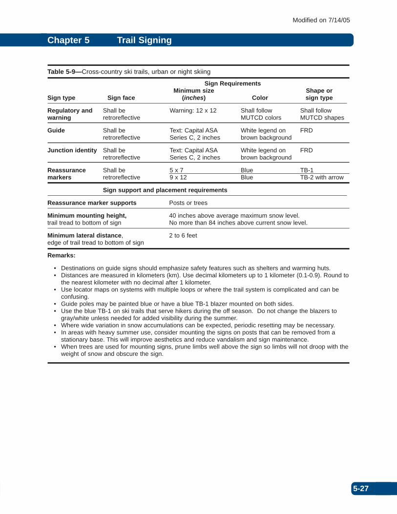
Table 5-9—Cross-country ski trails, urban or night skiing
Sign RequirementsMinimum size Shape or
Sign type Sign face (inches) Color sign type
Regulatory and Shall be Warning: 12 x 12 Shall follow Shall follow warning retroreflective MUTCD colors MUTCD shapes
Guide Shall be Text: Capital ASA White legend on FRDretroreflective Series C, 2 inches brown background
Junction identity Shall be Text: Capital ASA White legend on FRDretroreflective Series C, 2 inches brown background
Reassurance Shall be 5 x 7 Blue TB-1markers retroreflective 9 x 12 Blue TB-2 with arrow
Sign support and placement requirements
Reassurance marker supports Posts or trees
Minimum mounting height, 40 inches above average maximum snow level.trail tread to bottom of sign No more than 84 inches above current snow level.
Minimum lateral distance, 2 to 6 feetedge of trail tread to bottom of sign
Remarks:
• Destinations on guide signs should emphasize safety features such as shelters and warming huts.• Distances are measured in kilometers (km). Use decimal kilometers up to 1 kilometer (0.1-0.9). Round to
the nearest kilometer with no decimal after 1 kilometer.• Use locator maps on systems with multiple loops or where the trail system is complicated and can be
confusing.• Guide poles may be painted blue or have a blue TB-1 blazer mounted on both sides. • Use the blue TB-1 on ski trails that serve hikers during the off season. Do not change the blazers to
gray/white unless needed for added visibility during the summer. • Where wide variation in snow accumulations can be expected, periodic resetting may be necessary. • In areas with heavy summer use, consider mounting the signs on posts that can be removed from a
stationary base. This will improve aesthetics and reduce vandalism and sign maintenance. • When trees are used for mounting signs, prune limbs well above the sign so limbs will not droop with the
weight of snow and obscure the sign.
5-28
Chapter 5 Trail Signing
Modified on 7/14/05
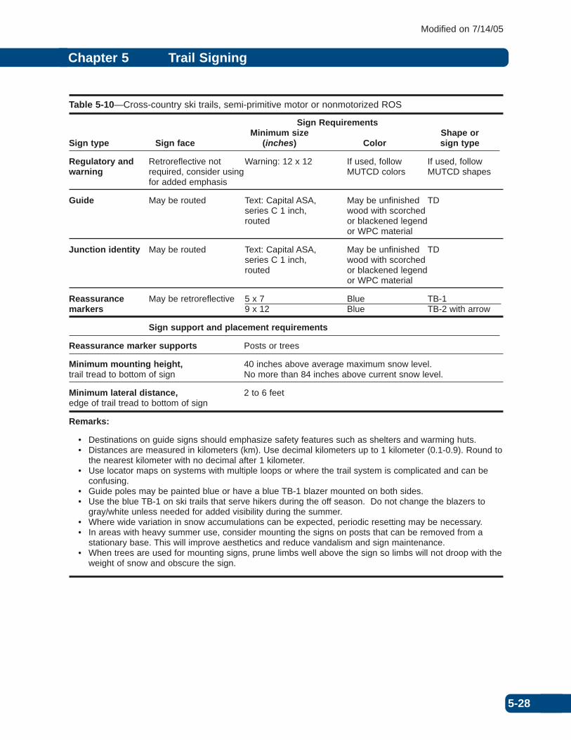
Table 5-10—Cross-country ski trails, semi-primitive motor or nonmotorized ROS
Sign RequirementsMinimum size Shape or
Sign type Sign face (inches) Color sign type
Regulatory and Retroreflective not Warning: 12 x 12 If used, follow If used, followwarning required, consider using MUTCD colors MUTCD shapes
for added emphasis
Guide May be routed Text: Capital ASA, May be unfinished TD series C 1 inch, wood with scorched routed or blackened legend
or WPC material
Junction identity May be routed Text: Capital ASA, May be unfinished TD series C 1 inch, wood with scorched routed or blackened legend
or WPC material
Reassurance May be retroreflective 5 x 7 Blue TB-1markers 9 x 12 Blue TB-2 with arrow
Sign support and placement requirements
Reassurance marker supports Posts or trees
Minimum mounting height, 40 inches above average maximum snow level.trail tread to bottom of sign No more than 84 inches above current snow level.
Minimum lateral distance, 2 to 6 feetedge of trail tread to bottom of sign
Remarks:
• Destinations on guide signs should emphasize safety features such as shelters and warming huts.• Distances are measured in kilometers (km). Use decimal kilometers up to 1 kilometer (0.1-0.9). Round to
the nearest kilometer with no decimal after 1 kilometer.• Use locator maps on systems with multiple loops or where the trail system is complicated and can be
confusing.• Guide poles may be painted blue or have a blue TB-1 blazer mounted on both sides. • Use the blue TB-1 on ski trails that serve hikers during the off season. Do not change the blazers to
gray/white unless needed for added visibility during the summer. • Where wide variation in snow accumulations can be expected, periodic resetting may be necessary. • In areas with heavy summer use, consider mounting the signs on posts that can be removed from a
stationary base. This will improve aesthetics and reduce vandalism and sign maintenance. • When trees are used for mounting signs, prune limbs well above the sign so limbs will not droop with the
weight of snow and obscure the sign.

5-29
Chapter 5 Trail Signing
Modified on 7/14/05
Table 5-11—Bicycle trail, paved or coincident with roads
Sign Requirements
Minimum size Shape or Sign type Sign face (inches) Color sign type
Regulatory and Shall be Shall follow MUTCD Shall follow Shall followwarning retroreflective Table 9B-1 MUTCD colors MUTCD shapes
Warning: 18 x 18
Guide Shall be Text: Capital ASA White legend on FRD retroreflective Series C, 2 inches brown background
Junction identity Shall be Text: Capital ASA White legend on FRD retroreflective Series C, 3 inches brown background
Reassurance Shall be 12 inches White legend on Federal Rec.markers retroreflective brown background Symbol RL-090
Sign support and placement requirements
Reassurance marker supports Posts or trees
Minimum mounting height,trail tread to bottom of sign 4 feet with 5 foot maximum
Minimum lateral distance,edge of trail tread 3 to 6 feetto nearest edge of sign
Remarks:
• Standards shall be in accordance with the MUTCD, Part 9, Traffic Controls for Bicycle Facilities.
5-30
Chapter 5 Trail Signing
Modified on 7/14/05
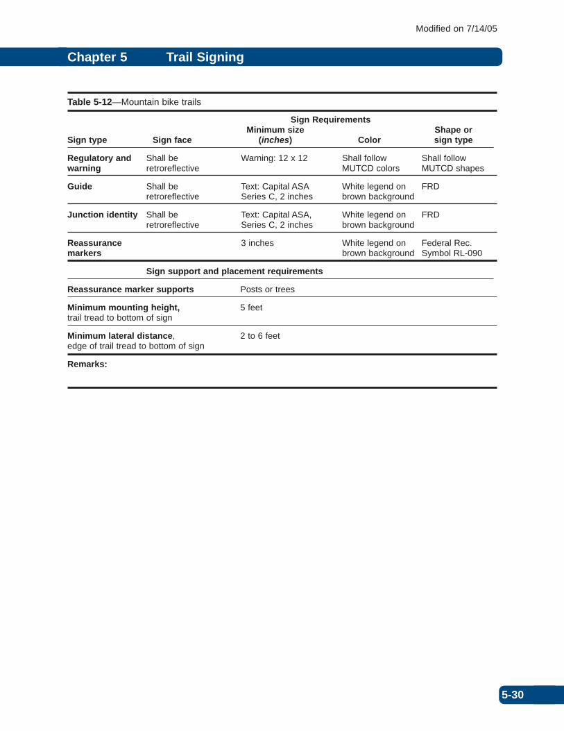
Table 5-12—Mountain bike trails
Sign RequirementsMinimum size Shape or
Sign type Sign face (inches) Color sign type
Regulatory and Shall be Warning: 12 x 12 Shall follow Shall followwarning retroreflective MUTCD colors MUTCD shapes
Guide Shall be Text: Capital ASA White legend on FRD retroreflective Series C, 2 inches brown background
Junction identity Shall be Text: Capital ASA, White legend on FRD retroreflective Series C, 2 inches brown background
Reassurance 3 inches White legend on Federal Rec.markers brown background Symbol RL-090
Sign support and placement requirements
Reassurance marker supports Posts or trees
Minimum mounting height, 5 feettrail tread to bottom of sign
Minimum lateral distance, 2 to 6 feetedge of trail tread to bottom of sign
Remarks:

5-31
Chapter 5 Trail Signing
Modified on 7/14/05
Table 5-13—ATV/motorcycle trails
Sign RequirementsMinimum size Shape or
Sign type Sign face (inches) Color sign type
Regulatory and Shall be Warning: 12 x 12 Shall follow Shall followwarning retroreflective MUTCD colors MUTCD shapes
Guide Shall be Text: Capital ASA White legend on FRD retroreflective Series C, 2 inches brown background
Junction identity Shall be Text: Capital ASA White legend on FRDretroreflective Series C, 2 inches brown background
Reassurance Shall be 3 inches White legend on Federal Recreation markers retroreflective brown background Symbol RL-150 or
RL-170
Sign support and placement requirements
Reassurance marker supports Posts or trees
Minimum mounting height,trail tread to bottom of sign 5 feet
Minimum lateral distance,edge of trail tread 2 to 6 feetto nearest edge of sign
Remarks:

5-32
Chapter 5 Trail Signing
Modified on 7/14/05
Table 5-14—Snowmobile trails
Sign RequirementsMinimum size Shape or
Sign type Sign face (inches) Color sign type
Regulatory and Shall be Warning: 12 x 12 Shall follow Shall followwarning retroreflective MUTCD colors MUTCD shapes
Guide Shall be Text: Capital ASA White legend on FRD retroreflective Series C, 2 inches brown background
Junction identity Shall be Text: Capital ASA White legend on 9 inch x 12 inch retroreflective Series C, 2 inches brown background diamond or rectangle
(minimum 4 inch)
Reassurance Shall be 5 x 7 Orange or TB-1 plastic blazermarkers retroreflective 9 x 12 fluorescent orange TB-2 with arrow
Sign support and placement requirements
Reassurance marker supports Posts or trees
Minimum mounting height, 40 inches above average maximum snow leveltrail tread to bottom of sign No more than 84 inches above current snow level
Minimum lateral distance, 2 to 6 feetedge of trail tread to bottom of sign
Remarks:
• Destinations on guide signs should emphasize safety features such as shelters and warming huts.• Use a location map showing the trail system, groomed or ungroomed conditions, and a “YOU ARE
HERE” arrow at each intersection for user orientation and security. .• Guide poles may be painted orange, have a orange TB-1 blazer mounted on both sides, or be wrapped
with retroreflective orange tape. • Where wide variation in snow accumulations can be expected, periodic resetting may be necessary. • In areas with heavy summer use, consider mounting the signs on posts that can be removed from a
stationary base. This will improve aesthetics and reduce vandalism and sign maintenance. • When trees are used for mounting signs, prune limbs well above the sign so limbs will not droop with the
weight of snow and obscure the sign.

5-33
Chapter 5 Trail Signing
Modified on 7/14/05
Table 5-15—Water trails
Sign RequirementsMinimum size Shape or
Sign type Sign face (inches) Color sign type
Regulatory and Shall be Warning: 12 x 12 Shall follow Shall followwarning retroreflective MUTCD colors MUTCD shapes
Guide Shall be Text: Capital ASA White legend on FRD retroreflective Series C, 2 inches brown background
Junction identity Shall be Text: Capital ASA White legend on FRDretroreflective Series C, 2 inches brown background
Reassurance Shall be 3 inches White on brown Federal Rec. markers retroreflective Symbol RW-020
Sign support and placement requirements
Reassurance marker supports Posts or trees
Minimum mounting height,trail tread to bottom of sign 5 feet above high water level
Minimum lateral distance,edge of trail tread 2 to 6 feetto nearest edge of sign
Remarks: