chapter 6 ocks - a.g it solution
TRANSCRIPT

226
Chapter 6ORTHOGRAPHIC PROJECTIONS OF SIMPLE MACHINE BLOCKS
6.1 INTRODUCTION
We have already made you aware of many simple geometrical shapes (laminae), projected on such planes (vertical plane, horizontalplane and other auxiliary planes) while projecting the various views of simple regular geometrical solids. Similarly, it is necessary tounderstand any machine block ascombination of the geometrical solids byadding solids together or removinggeometrical solids out of a single solid. Forexample, a hexagonal nut is formed out of ahexagonal prism by removing a smallcylinder and cutting internal helical groove(internal threads). Reverse of it is square boltin which square prism and small cylinder isone integral solid with external helicalgroove (external threads) cut on it.
In figure 6.1 a cube of 15 mm is removed outfrom a single solid i.e. a rectangular prism.
An orthographic projection is one positiondrawing. It takes several drawings to showand understand all the machine block form.The views are placed relative to each otheraccording to either of two schemes. FIRSTANGLE PROJECTION METHOD OR THIRDANGLE PROJECTION METHOD.
Note : However we are following only firstangle method of projection in all theexercises (According to CBSE prescribedsyllabus) Fig. 6.1

227
Orthographic projections of simple machine blocks
6.2 UNDERSTANDING : SIMPLE MACHINE BLOCKS
FIG. 6.2 DO IT YOURSELF(i) No. of Vertical Faces..............(ii) No. of Horizontal Faces...........(iii) Give the dimension of Face ‘H1’ ...................(iv) Give the dimension of Face ‘V1’ ......................(v) No. of side Faces .....................
V = Vertical Face, H = Horizontal Face, I = Inclined Face, F = Front, S = Side and T = Top

228
Engineering Graphics
FIG. 6.3 DO IT YOURSELF(i) No. of Vertical faces..............(ii) No. of Horizontal faces...........(iii) Give the dimension of face ‘V1’ ...................(iv) Give the dimension of face ‘H1’ ......................(v) No. of side faces .....................
V = Vertical Face, H = Horizontal Face, I = Inclined Face, F = Front, S = Side and T = Top

229
Orthographic projections of simple machine blocks
FIG. 6.4 DO IT YOURSELF
(i) No. of Vertical faces..............
(ii) No. of Horizontal faces...........
(iii) No. of Inclined faces.............
(iv) Give the dimension of face I in Top View ......................
Note : This inclined face is seen in Top View and in Front View
V = Vertical Face, H = Horizontal Face, I = Inclined Face, F = Front, S = Side and T = Top

230
Engineering Graphics
FIG. 6.5 DO IT YOURSELF
(i) No. of Vertical faces..............
(ii) No. of Horizontal faces...........
(iii) No. of Inclined faces.............
(iv) Give the dimension of face I in Side View ..................
Note : This inclined face is seen in Top View and in Front View
V = Vertical Face, H = Horizontal Face, I = Inclined Face, F = Front, S = Side and T = Top

231
Orthographic projections of simple machine blocks
IMPORTANT OBSERVATIONS :
If the surface/face of an object is either parallel to the vertical plane or horizontal plane (Principal Planes) they appear to be inTRUE SHAPE in one of the three views and appear as a “line only” in other two views (as these faces are perpendicular to theplane of projection).
When a surface/face is inclined or making an angle with two planes at the same time, that surface/face is not seen in its TRUESHAPE in the plane to which it is inclined. It is seen in the plane to which it is inclined as a plane of reduced size due toforeshortening.
6.3 LET US FIND
Fill in the blanks by the corresponding line (as indicated)/Trueshape by observing the following views.
Pictorial View Orthographic View
Surfaces Indicated As
Front View Top View Side View
(I) H ______1_____ True Shape ______2_____
(ii) H1 ____________ ____________ ____________
(iii) V ____________ ____________ ____________
(iv) S ____________ ____________ ____________
(v) S1 ____________ ____________ ____________
Fig. 6.6

232
Engineering Graphics
6.4 MACHINE BLOCKS WITH (HORIZONTAL AND VERTICAL FACES)
Fig. 6.7

233
Orthographic projections of simple machine blocks
Fig. 6.8

234
Engineering Graphics
Fig. 6.9

235
Orthographic projections of simple machine blocks
Fig. 6.10

236
Engineering Graphics
Fig. 6.11
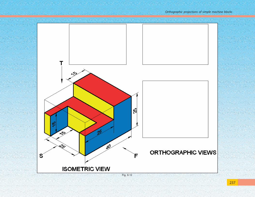
237
Orthographic projections of simple machine blocks
Fig. 6.12

238
Engineering Graphics
Fig. 6.13

239
Orthographic projections of simple machine blocks
Fig. 6.14

240
Engineering Graphics
Fig. 6.15
6.5 MACHINE BLOCKS WITH (HORIZONTAL, VERTICAL AND INCLINED FACES)
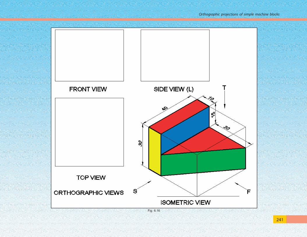
241
Orthographic projections of simple machine blocks
Fig. 6.16

242
Engineering Graphics
Fig. 6.17

243
Orthographic projections of simple machine blocks
Fig. 6.18

244
Engineering Graphics
Fig. 6.19
6.6 MACHINE BLOCKS : (HORIZONTAL, VERTICAL AND CURVED FACES)

245
Orthographic projections of simple machine blocks
Fig. 6.20

246
Engineering Graphics
Fig. 6.21

247
Orthographic projections of simple machine blocks
Fig. 6.22

248
Engineering Graphics
Fig. 6.23
6.7 MACHINE BLOCKS : (HORIZONTAL, VERTICAL, CURVED AND INCLINED FACES)

249
Orthographic projections of simple machine blocks
Fig. 6.24
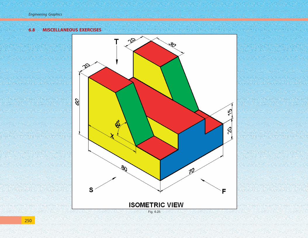
250
Engineering Graphics
6.8 MISCELLANEOUS EXERCISES
Fig. 6.25

251
Orthographic projections of simple machine blocks
Fig. 6.26

252
Engineering Graphics
Fig. 6.27

253
Orthographic projections of simple machine blocks
Fig. 6.28
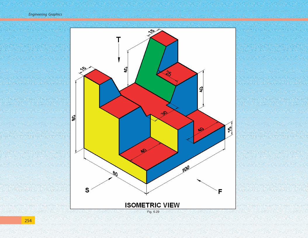
254
Engineering Graphics
Fig. 6.29

255
Orthographic projections of simple machine blocks
Fig. 6.30

256
Engineering Graphics
Fig. 6.31

257
Orthographic projections of simple machine blocks
Fig. 6.32

258
Engineering Graphics
Fig. 6.33

259
Orthographic projections of simple machine blocks
Fig. 6.34
260
Engineering Graphics
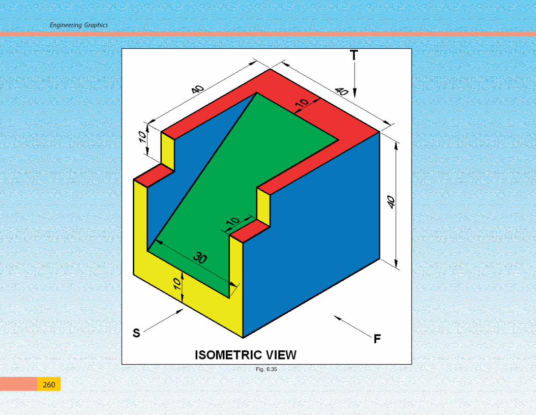
Fig. 6.35

261
Orthographic projections of simple machine blocks
Fig. 6.36