chapter 6 polymer-matrix composites - freenguyen.hong.hai.free.fr/ebooks/science and...
TRANSCRIPT

CHAPTER 6 Polymer-Matrix Composites
Polymers
Polymer-matrix composites are much easier to fabricate than metal- matrix, carbon-matrix, and ceramic-matrix composites, whether the polymer is a thermoset or a thermoplast. This is because of the relatively low processing temperatures required for fabricating polymer-matrix composites. For thermo- sets, such as epoxy, phenolic, and furfuryl resin, the processing temperature typically ranges from room temperature to about 200°C; for thermoplasts, such as polyimide (PI), polyethersulfone (PES), polyetheretherketone (PEEK), polyetherimide (PEI), and polyphenyl sulfide (PPS), the processing tempera- ture typically ranges from 300 to 400°C.
Thermosets (especially epoxy) have long been used as polymer matrices for carbon fiber composites. During curing, usually performed in the presence of heat and pressure, a thermoset resin hardens gradually due to the completion of polymerization and the cross-linking of the polymer molecules. Thermoplasts have recently become important because of their greater ductility and processing speed compared to thermosets, and the recent availability of thermoplasts that can withstand high temperatures. The higher processing speed of thermoplasts is due to the fact that thermoplasts soften immediately upon heating above the glass transition temperature (T,) and the softened material can be shaped easily. Subsequent cooling completes the processing. In contrast, the curing of a thermoset resin is a reaction which occurs gradually.
Epoxy is by far the most widely used polymer matrix for carbon fibers. Trade names of epoxy include Epon, Epi-rez, and Araldite. Epoxy has an excellent combination of mechanical properties and corrosion resistance, is dimensionally stable, exhibits good adhesion, and is relatively inexpensive. Moreover, the low molecular weight of uncured epoxide resins in the liquid state results in exceptionally high molecular mobility during processing. This mobility enables the resin to quickly wet the surface of carbon fiber, for example.
85

86 CARBON FIBER COMPOSITES
Epoxy resins are characterized by having two or more epoxide groups per molecule. The chemical structure of an epoxide group is:
where Be = benzene ring. For liquids, n is usually less than 1; for solid resins, n is 2 or greater.
The curing of an epoxy resin requires a cross-linking agent and/or a catalyst. The epoxy and hydroxyl groups (-OH) are the reaction sites for cross-linking. Cross-linking agents include amines, anhydrides, and aldehyde condensation products. In the curing reaction, the epoxide ring is opened (called ring scission) and a donor hydrogen from, say, an amine or hydroxyl group bonds with the oxygen atom of the epoxide group. Ethylene diamine is an amine which serves as a cross-linking agent.
Epoxide groups at Ethylene Cross-link formed the ends of two diamine between two linear linear epoxy molecules epoxy molecules
As no by-product is given off during curing, shrinkage is low.
are shown below, where Be = benzene ring. The mers (repeating units) of typical thermoplasts used for carbon fibers

Polymer-Matrix Composites 87
The properties of the above thermoplasts are listed in Table 6.1. In contrast, epoxies have tensile strengths of 30-100 MPa, moduli of elasticity of 2.8-3.4 GPa, ductilities of 0 4 % and a density of 1.25g/cm3 [3]. Thus, epoxies are much more brittle than PES, PEEK, and PEI. In general, the ductility of a semicrystalline thermoplast decreases with increasing crystallinity. For example, the ductility of PPS can range from 2 to 20%, depending on the
Table 6.1 Properties of thermoplasts for carbon fiber polymer-matrix composites.
PES PEEK PEI PPS PI
Tg ("C) 230" 170" 225" 86" 256b Decomposition temperature ("C) 550" 590" 555" 527" 550b Processing temperature ("C) 350" 380" 350a 316" 304b Tensile strength (MPa) 84' 70' 105' 66' 138b Modulus of elasticity (GPa) 2.4' 3.8' 3.0" 3.3" 3.4b Ductility (% elongation) 30-80' 50-150' 5M5' 2' 5b
Izod impact (ft lbhn.) 1.6' 1.6' 1' <OS' 1.5' Density (g/cm3) 1.37' 1.31' 1.27' 1.3' 1.37b
"From Ref. 1. bFrom Ref. 2. 'From Ref. 3.

88 C A R B O N FIBER COMPOSITES
crystallinity [4]. Another major difference between thermoplasts and epoxies lies in the higher processing temperatures of thermoplasts (3WOO"C).
Much work has been done to improve epoxies for controlling the fiber-matrix interface [5,6], increasing the toughness [7,8], and reducing the moisture sensitivity [9]. Other than epoxies, thermosets used for carbon fibers include polyimide [ 101 and bismaleimide [ 11,121. (Polyimides can be thermo- plasts or thermosets.)
Semicrystalline thermoplasts (e.g., PEEK) are more efficiently reinforced than are amorphous thermoplasts (e.g., PES). This is because the fibers act as nucleation sites for crystallization; the fiber becomes surrounded by a microcrystalline structure, which binds the fiber more firmly to the polymer and improves the modulus. Furthermore, the degree of reinforcement in- creases with the degree of crystallinity [13].
The addition of fibers increases the softening temperature of a thermo- plast and the effect is greater with semicrystalline polymers than with amorphous polymers, where the gain is typically 10-20°C. This is because softening is governed by Tg for an amorphous polymer, but is governed by the melting point (T,) and the degree of crystallinity for a semicrystalline polymer
The addition of fibers increases the creep resistance because it impedes the molecular mobility. The effect is greater with amorphous thermoplasts than with semicrystalline thermoplasts, as crystalline polymers themselves inhibit creep [13].
Water absorbed by a polymer acts as a plasticizer and decreases strength and stiffness, but increases toughness. As fibers absorb much less water than polymers, addition of fibers decreases the amount of water absorption [13]. It also increases the dimensional stability when the temperature is changed, because fibers have much lower thermal expansion coefficients than polymers
The use of fibers produces higher melt viscosities at a given shear rate, so higher processing temperatures and/or higher injection pressures are necessary. On the other hand, the addition of fibers reduces shrinkage during processing
~ 3 1 .
~ 3 1 .
~ 3 1 .
Surface Treatments of Carbon Fibers for Polymer Matrices
Surface treatments of carbon fibers are essential for improving the bonding between the fibers and the polymer matrix. They involve oxidation treatments and the use of coupling agents, wetting agents, and/or sizings (coatings). Carbon fibers need treatment both for thermosets and thermo- plasts. As the processing temperature is usually higher for thermoplasts than thermosets, the treatment must be stable to a higher temperature (300-400"C) when a thermoplast is used.
Oxidation treatments can be applied by gaseous, solution, electro- chemical, and plasma (e.g., acid plasma [14]) methods. They serve mainly to
Polymer-Matrix Composites 89
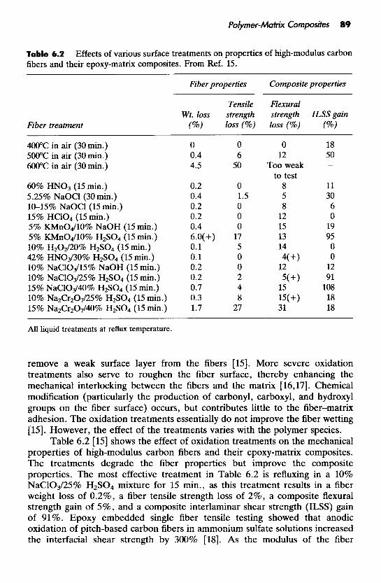
Table 6.2 fibers and their epoxy-matrix composites. From Ref. 15.
Effects of various surface treatments on properties of high-modulus carbon
Fiber treatment
Fiber properties Composite properties
Tensile Flexural Wt. loss strength strength ILSS gain
(%) loss (%) loss (%) (%)
400°C in air (30 min.) 500°C in air (30 rnin.) 600°C in air (30 rnin.)
60% HN03 (15 rnin.) 5.25% NaOCl (30 min.) 10-15% NaOCl (15 min.) 15% HC104 (15 min.) 5% KMn04/10% NaOH (15 min.) 5% KMn04/10% HzS04 (15 min.) 10% HzOZ/20% H2SO4 (15 min.) 42% HN03/30% HzSO4 (15 min.) 10% NaC103/15% NaOH (15 min.) 10% NaC103/25% HzSO4 (15 min.) 15% NaClO&IO% H2SO4 (15 rnin.) 10% NazCr207/25% HzSO4 (15 min.) 15% Na2Cr207/40% H2SO4 (15 min.)
0 0 0.4 6 4.5 50
0.2 0 0.4 1.5 0.2 0 0.2 0 0.4 0 6.0(+) 17 0.1 5 0.1 0 0.2 0 0.2 2 0.7 4 0.3 8 1.7 27
0 12
Too weak to test
8 5 8
12 15 13 14 4(+)
12
18 50
11 30 6 0
19 95 0 0
12 91
108 18 18
All liquid treatments at reflux temperature.
remove a weak surface layer from the fibers [15]. More severe oxidation treatments also serve to roughen the fiber surface, thereby enhancing the mechanical interlocking between the fibers and the matrix [16,17]. Chemical modification (particularly the production of carbonyl, carboxyl, and hydroxyl groups on the fiber surface) occurs, but contributes little to the fiber-matrix adhesion. The oxidation treatments essentially do not improve the fiber wetting [15]. However, the effect of the treatments varies with the polymer species.
Table 6.2 [15] shows the effect of oxidation treatments on the mechanical properties of high-modulus carbon fibers and their epoxy-matrix composites. The treatments degrade the fiber properties but improve the composite properties. The most effective treatment in Table 6.2 is refluxing in a 10% NaC103/25% H2S04 mixture for 15 min., as this treatment results in a fiber weight loss of 0.2%, a fiber tensile strength loss of 2%, a composite flexural strength gain of 5%, and a composite interlaminar shear strength (ILSS) gain of 91%. Epoxy embedded single fiber tensile testing showed that anodic oxidation of pitch-based carbon fibers in ammonium sulfate solutions increased the interfacial shear strength by 300% [MI. As the modulus of the fiber

90 CARBON FIBER COMPOSITES
Table 6.3 Interfacial shear strength of carbon fibers in an epoxy matrix. From Ref. 19.
Fiber Interfacial shear strength (MPa)
AU-1 AS-1 AU-4 AS-4
48 14 31 61
increases, progressively longer treatment times are required to attain the same improvement in ILSS. Although the treatment increases ILSS, it decreases the impact strength (i.e., impact energy), so the treatment time must be carefully controlled in order to achieve a balance in properties. The choice of treatment time also depends on the particular fiber-resin combination used. For a particular treatment, as the modulus of the fiber increases, the treatment’s positive effect on the ILSS and its negative effect on the impact strength both become more severe [15].
Commercial carbon fibers are surface treated to enhance the bonding with epoxy, though the surface treatment is proprietary. Table 6.3 [19] shows the effect of a surface treatment on the interfacial shear strength for PAN-based carbon fibers manufactured by Hercules. In Table 6.3, fibers designated AS-1 and AS-4 are typical Type I1 intermediate strain fibers, whereas AU-1 and AU-4 are the untreated analogs of AS-1 and AS-4, respectively. The interfacial shear strength was determined from the critical shear transfer length, Le., the length of the fiber fragments after fracture of a single fiber pulled in tension while being encapsulated in epoxy. Surface treatment increased the interfacial shear strength by 54 and 65% for AS-1 and AS-4 fibers, respectively [19]. Table 6.4 [19] shows the atomic surface concentrations of AS-1 and AS-4 fibers, as determined by X-ray photoelectron spectroscopy. The atomic surface concentrations are similar for AS-1 and AS-4, indicating that the superior interfacial shear strength of AS-1 compared to AS-4 is not due to a difference in the surface composition. On the other hand, scanning electron microscopy shows that the surface of AS-1 is corrugated, whereas that of AS-4 is smooth. Therefore, the superior interfacial shear strength of AS-1 is attributed to its surface morphology, which increases its surface area and enhances the mechanical interlocking between the fiber and the matrix [19].
Although surface treatments of carbon fibers result in some degree of oxidation, which places oxygen on the surface in an acidic form, the treatments themselves produce little acidity. Surface acidification is not desirable because it is accompanied by surface degradation [20].
The oxidation treatments approximately double the surface concentration

Polymer-Matrix Composites 9 1
Table 6.4 Ref. 19.
Atomic surface concentrations of the carbon fibers of Table 6.3. From
Atomic percent
Fiber ClS 0 1 s Nls S2P N ~ K L L
AS- 1 84 11 4.3 0.2 1.0 AS-4 83 12 4.0 0.2 0.7
of oxygen. Functional groups on the fiber surface and at 500 8, below the surface are listed below in relative order of abundance.
The main functional groups produced are carbonyl, carboxyl, and hydroxyl
The oxygen concentration does not determine or correlate with the increase in ILSS or transverse tensile strength of the composites [ 15,161. Indeed, the addition of the surface chemical oxygen groups is believed to be responsible for only 10% of the increase in adhesion resulting from the treatment; only about 4% of the surface sites of the carbon fibers are involved in chemical bonding with the epoxy and amine groups of the polymer. Although the magnitude of the bond strength for chemical bonds is very high, the quantity of bonds is low [21]. On the other hand, elimination of the functional groups on the treated fibers by diazomethane causes the ILSS to decrease toward the level of the untreated fibers [22], so the contribution of the functional groups to fiber-matrix adhesion cannot be neglected.
In addition to oxidation treatments, carbon fibers require the use of coupling agents, wetting agents, and/or sizings (coatings) in order to improve the wetting of the fibers by the polymer, the adhesion between the fibers and the matrix, and the handleability of the fibers. As one agent often serves more than one function, the distinction among coupling agents, wetting agents, and sizings is often vague.
1151.

92 CARBON FIBER COMPOSITES
Coupling agents [ 15,231 are mostly short-chain hydrocarbon molecules, one end of which is compatible or interacts with the polymer while the other end interacts with the fiber. A coupling agent molecule has the form X-R, where X interacts with the fiber and R is compatible or interacts with the polymer.
Organosilanes are of the form R-Si-(OX)3, where X is methyl, ethyl, methoxyethyl, etc., and R is a suitable hydrocarbon chain. They are widely used as coupling agents between glass fibers and thermosets, as the -OX groups react with the -OH groups on the glass surface.
However, organosilanes do not function for carbon, organic, or metallic fibers. Organotitanates and organozirconates function as coupling agents for
both siliceous (e.g., glass) and nonsiliceous (e.g., carbon) fillers. The general formula of the organotitanates is:
where R is usually a short-chain hydrocarbon such as C8HI7 and X is a group capable of interacting with the fiber. Organotitanates and organozirconates in amounts of 0.1-0.5 wt. % of formulation solids provide improved bonding between carbon fibers and thermosets (e.g., epoxy, polyurethane, polyester, and vinyl ester resins) [24].
Wetting agents are polar molecules with one end attracted to the fiber and the other end to the polymer. The agent forms a protective layer around the fiber, thereby improving dispersion. It also promotes adhesion by allowing more efficient wetting of the polymer on the fiber. The main difference between a wetting agent and a coupling agent is that a coupling agent forms a chemical bond with the fiber but a wetting agent does not [15].
Sizings (coatings or finishes) are commonly applied to carbon fibers in order to improve fiber-polymer adhesion and fiber handleability. The handle- ability is particularly important if the fibers are to be woven. The choice of sizing material depends on the polymer matrix. In particular, thermoplast- matrix composites require sizings that can withstand higher temperatures than
Polymer-Matrix Composites 93
thermoset-matrix composites, because of the higher processing temperature of the fiber. Sizing materials include prepolymers/polymers, carbon, Sic, and metals. Due to the relative ease of application, polymers (either cured or partially cured) are the most common sizing materials. Sizing thicknesses typically range from 0.1 to 1 pm.
Commercial carbon fibers are usually coated with a proprietary epoxy- compatible finish. Nevertheless, epoxy is the main sizing material for fibers used for epoxy-matrix composites. As the epoxy sizing decomposes at about 250°C, it is not very suitable for thermoplast-matrix composites, though it is still useful [25]. Instead, polyimides and polyimide-PES blends are used as sizings for carbon fibers in thermoplast-matrix composites. Polyimide-coated carbon fibers can withstand temperatures up to 450°C [I].
Other than epoxy, a number of polymers have been used as sizings for carbon fibers in epoxy-matrix composites. They include polyhydroxyether, polyphenyleneoxide, copolymers of styrene and maleic anhydride (SMA), a block copolymer of SMA with isoprene, polysulfone, polybutadiene, silicone, a carboxy-terminated polybutadiene/acrylonitrile copolymer, a copolymer of maleic anhydride and butadiene, and a copolymer of ethylene and acrylic acid [26]. In particular, an SMA coating results in a 50% increase in the interfacial shear strength (measured by using a single fiber) compared with commercially treated fibers, while causing no degradation in the impact strength (271. In contrast, elastomer coatings result in improved crack resistance and impact strength [28].
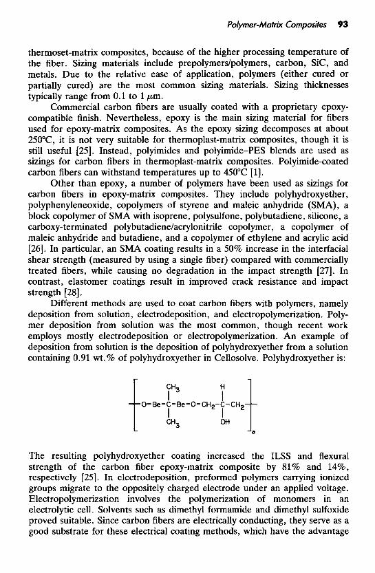
Different methods are used to coat carbon fibers with polymers, namely deposition from solution, electrodeposition, and electropolymerization. Poly- mer deposition from solution was the most common, though recent work employs mostly electrodeposition or electropolymerization. An example of deposition from solution is the deposition of polyhydroxyether from a solution containing 0.91 wt. % of polyhydroxyether in Cellosolve. Polyhydroxyether is:
The resulting polyhydroxyether coating increased the ILSS and flexural strength of the carbon fiber epoxy-matrix composite by 81% and 1476, respectively [25]. In electrodeposition, preformed polymers carrying ionized groups migrate to the oppositely charged electrode under an applied voltage. Electropolymerization involves the polymerization of monomers in an electrolytic cell. Solvents such as dimethyl formamide and dimethyl sulfoxide proved suitable. Since carbon fibers are electrically conducting, they serve as a good substrate for these electrical coating methods, which have the advantage

94 CARBON FIBER COMPOSITES
Table 6.5 From Ref. 22.
Effect of oxidation treatment and polymer coating on ILSS of composite.
Oxidation Polymer Polymer Density ILSS coating (%) (dcm3) ( M W
None None - 1.28 16.2
60% HN03, 24 h. None - 1.29 24.3 PVA 7 1.31 42.8 PVC 7 1.31 42.1 Rigid polyurethane 3 1.27 40.7 PAN 7 1.27 16.6
of yielding uniform layers of readily controlled thickness in just a short time [29]. Sometimes grafting of the polymer to the fiber surface takes place, as in the case of the electrochemical oxidation of w-diamines on carbon fibers, where the grafting provides a continuous succession of covalent bonds from the carbon fiber surface to the epoxy resin [30]. Deposition techniques have given the greatest improvement in composite properties-up to 60% in impact strength, 84% in work to fracture, and 90% in ILSS, but not simultaneously [26]. Table 6.5 [21] shows the effect of oxidation treatment and polymer coating on ILSS. The use of both oxidation treatment and polymer coating give the highest ILSS.
The sizing increases the ILSS; this changes the mode of composite fracture from growth of an interfacial crack to growth of a crack perpendicular to the fiber axis [15]. In some cases, the epoxy matrix penetrates the polymer coating [26]. An interphase between the fiber and the epoxy matrix is believed to exist. It is a three-dimensional region including not only the two-dimensional fiber-matrix interface, but also regions on both sides of the interface
The polymer sizings are chemically bonded to the carbon fiber via its functional groups. In the case of an epoxy sizing, the epoxy group and amine group can react with the functional groups on the fiber surface [21]. Furthermore, the functional groups act as a catalyst for cross-linking, if their concentrations are not too high [29]. In the case of a polyimide sizing, the carboxylic acid groups in polyimide precursors react with the functional groups on the fiber surface [l].
Far less common than polymer coatings are carbon, Sic, and metal coatings on carbon fibers. Carbon coatings deposited by using acetylene vapor increase the ILSS from 34 MPa at 0 wt.% C coating to 56 MPa at 22 wt.% C coating [22]. Sic coatings, in the form of p-Sic single crystal whiskers grown on the carbon fiber surface perpendicular to the fiber axis, significantly increase the ILSS [22]. Metal (Ni,Cu) coatings deposited by electroless plating or
[21,31-331.
Polymer-Matrix Composites 95
electroplating on carbon fibers provide polar surfaces due to the presence of oxides and hydration of the surface [34].
Classification
Carbon fiber polymer-matrix composites can be classified according to whether the matrix is a thermoset or a thermoplast. Thermoset-matrix composites are by tradition far more common, but thermoplast-matrix compo- sites are under rapid development. The advantages of thermoplast-matrix composites compared to thermoset-matrix composites include the following:
Lower manufacturing cost
0 no cure 0 unlimited shelf-life
reprocessing possible (for repair and recycling) 0 less health risks due to chemicals during processing
low moisture content 0 thermal shaping possible 0 weldability (fusion bonding possible)
Better performance
0 high toughness (damage tolerance) good hot/wet properties high environmental tolerance
The disadvantages of thermoplast-matrix composites include the following:
limitations in processing methods high processing temperatures high viscosities
0 stiff and dry prepregs when a solvent is not used (Le., not drapeable or
fiber surface treatments less developed
Carbon fiber polymer-matrix composites can be classified according to whether the fibers are short or continuous. Continuous fibers have much more effect than short fibers on the composite’s mechanical properties, electrical resistivity, thermal conductivity, and on other properties, too. However, they give rise to composites that are more anisotropic. Continuous fibers can be in unidirectionally aligned tape or woven fabric form.
tacky)
Fabrication
Short-fiber composites are usually fabricated by mixing the fibers with a liquid resin to form a slurry then molding to form a composite. The liquid resin is the unpolymerized matrix material in the case of a thermoset; it is the molten
96 C A R B O N FIBER COMPOSITES
polymer or the polymer dissolved in a solvent in the case of a thermoplast. The molding methods are those conventionally used for polymers by themselves. For thermoplasts, the methods include injection molding (heating above the melting temperature of the thermoplast and forcing the slurry into a closed die by a plunger or a screw mechanism), extrusion (forcing the slurry through a die opening by using a screw mechanism), calendering (pouring the slurry into a set of rollers with a small opening between adjacent rollers to form a thin sheet), and thermoforming (heating above the softening temperature of the thermoplast and forming over a die (using matching dies, a vacuum, or air pressure), or without a die (using movable rollers)). For thermosets, compres- sion molding or matched die molding (applying a high pressure and tempera- ture to the slurry in a die to harden the thermoset) is commonly used. The casting of the slurry into a mold is not usually suitable because the difference in density between the resin and the fibers causes the fibers to float or sink, unless the viscosity of the resin is carefully adjusted. For forming a short-fiber composite coating, the fiber-resin slurry can be sprayed instead of molded.
Instead of using a fiber-resin slurry, short carbon fibers in the form of a mat or a continuous spun staple yarn can be impregnated with a resin and shaped using methods commonly used for continuous fiber composites. By using spun staple yarns from the Heltra process, researchers have produced epoxy-matrix composites that retain 97% of the tensile modulus and 70% of the tensile strength of their counterparts containing continuous carbon fiber tows. This is in spite of the discontinuity and slight twist in the fibers of the staple yarns [35].
Yet another method involves using continuous staple yams in the form of an intimate blend of short carbon fibers and short thermoplast fibers. The yarns may be woven, if desired. They do not need to be impregnated with a resin to form a composite, as the thermoplast fibers melt during consolidation under heat and pressure [35].
Since carbon fibers are electrically conducting, they can be aligned in an electric field. Short (1.6 cm) carbon fibers in a nylon matrix have been aligned in this way, such that on average 68% of the fibers were within f10" of perfect alignment [36].
Continuous fiber composites are commonly fabricated by hand lay-up of unidirectional fiber tapes or woven fabrics and impregnation with a resin. The molding, called bag molding, is done by placing the tapes or fabrics in a die and introducing high-pressure gases or a vacuum via a bag to force the individual plies together. Bag molding is widely used to fabricate large composite components for the skins of aircraft.
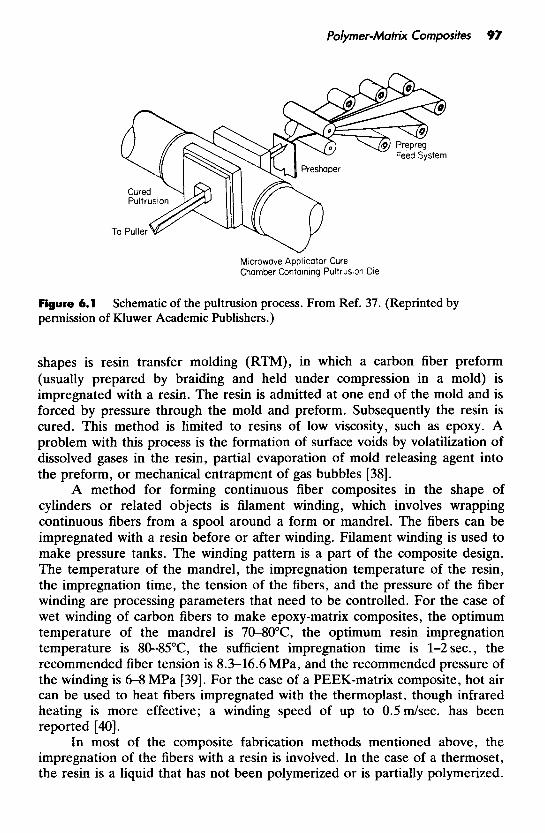
A method for forming unidirectional fiber composite parts with a constant cross section (e.g., round, rectangular, pipe, plate, I-shaped) is pultrusion, in which fibers are drawn from spools, passed through a polymer resin bath for impregnation, and gathered together to produce a particular shape before entering a heated die (Figure 6.1) [37].
A method for forming continuous carbon fiber composites of intricate
Polymer-Matrix Composites 97
Figure 6.1 permission of Kluwer Academic Publishers.)
Schematic of the pultrusion process. From Ref. 37. (Reprinted by
shapes is resin transfer molding (RTM), in which a carbon fiber preform (usually prepared by braiding and held under compression in a mold) is impregnated with a resin. The resin is admitted at one end of the mold and is forced by pressure through the mold and preform. Subsequently the resin is cured. This method is limited to resins of low viscosity, such as epoxy. A problem with this process is the formation of surface voids by volatilization of dissolved gases in the resin, partial evaporation of mold releasing agent into the preform, or mechanical entrapment of gas bubbles [38].
A method for forming continuous fiber composites in the shape of cylinders or related objects is filament winding, which involves wrapping continuous fibers from a spool around a form or mandrel. The fibers can be impregnated with a resin before or after winding. Filament winding is used to make pressure tanks. The winding pattern is a part of the composite design. The temperature of the mandrel, the impregnation temperature of the resin, the impregnation time, the tension of the fibers, and the pressure of the fiber winding are processing parameters that need to be controlled. For the case of wet winding of carbon fibers to make epoxy-matrix composites, the optimum temperature of the mandrel is 7&80"C, the optimum resin impregnation temperature is 8&85"C, the sufficient impregnation time is 1-2 sec., the recommended fiber tension is 8.3-16.6 MPa, and the recommended pressure of the winding is 6-8 MPa [39]. For the case of a PEEK-matrix composite, hot air can be used to heat fibers impregnated with the thermoplast, though infrared heating is more effective; a winding speed of up to 0.5dsec. has been reported [a].
In most of the composite fabrication methods mentioned above, the impregnation of the fibers with a resin is involved. In the case of a thermoset, the resin is a liquid that has not been polymerized or is partially polymerized.
98 C A R B O N FIBER COMPOSITES
In the case of a thermoplast, the resin is either the polymer melt or the polymer dissolved in a solvent. After resin application, solid thermoplast results from solidification in the case of melt impregnation, and from evaporation in the case of solution impregnation [41]. Both amorphous and semicrystalline thermoplasts can be melt processed, but only the amorphous resins can normally be dissolved. Because of the high melt viscosities of semicrystalline thermoplasts (e.g., about 370 Pa.sec. for PEEK at 370°C, compared to about 0.39 Pa.sec. for low-viscosity epoxy) due to their long and rigid macromolecular chains, direct melt impregnation of semicrystalline thermoplasts is difficult [35]. Melt impregnation followed by solidification produces a thermoplastic prepreg that is stiff and lacks tack; solution impregnation usually produces prepregs that are drapeable and tacky, although this character changes as solvent evaporation occurs from the solution. The drapeable and tacky character of thermoplastic prepregs made by solution impregnation is comparable to that of thermoset prepregs. Hence, the main problem with resin impregnation occurs for semicrystalline thermoplasts.
Instead of thermoplastic impregnation of fibers by using a melt or a solution of the thermoplast, solid thermoplast in the form of powder, fibers, or slurries can be impregnated [42]. For example, carbon fibers can be immersed in a suspension of a thermoplast powder in an aqueous liquid medium (which contains at least 20 wt.% of an organic liquid) to impregnate the thermoplast into the fibers [43].
An alternative to impregnation is the commingling of continuous carbon fibers with continuous thermoplast fibers. This commingling can be on a fabric level, where yarns of different materials are woven together (coweaving); it can be on a yarn level, where yams of different materials are twisted together; or it can be on a fiber level, where fibers of different materials are intimately mixed within a unidirectional fiber bundle [44]. During processing, such as compres- sion molding or filament winding, the thermoplast fibers melt, wet the carbon fibers and fuse to form the matrix [45]. However, there is a preferred orientation in the thermoplast fibers, due to the spinning process used in their production, and this may be a problem. Furthermore, the thermoplast fibers have a tendency to form drops during heating [46]. In addition, the availability of high-temperature thermoplast fibers is limited. PEEK is most commonly used for commingling with carbon fibers, but processing must be carried out at a sufficiently high temperature to destroy the previous thermal history of the PEEK matrix [47]. Fiber-matrix adhesion in a commingled system depends on the molding temperature, residence time at the melt temperature, and the cooling rate. This is probably due to several complex mechanisms such as matrix adsorption on the fiber surface, matrix degradation leading to chemical bonding, and interfacial crystallization [47]. On the other hand, prepregs made from commingled fibers are flexible and drapeable [35], and the use of three-dimensional braiding allows net structural shape formation and enhances the damage tolerance due to the lack of delamination [44]. To prevent the ends
Polymer-Matrix Composites 99
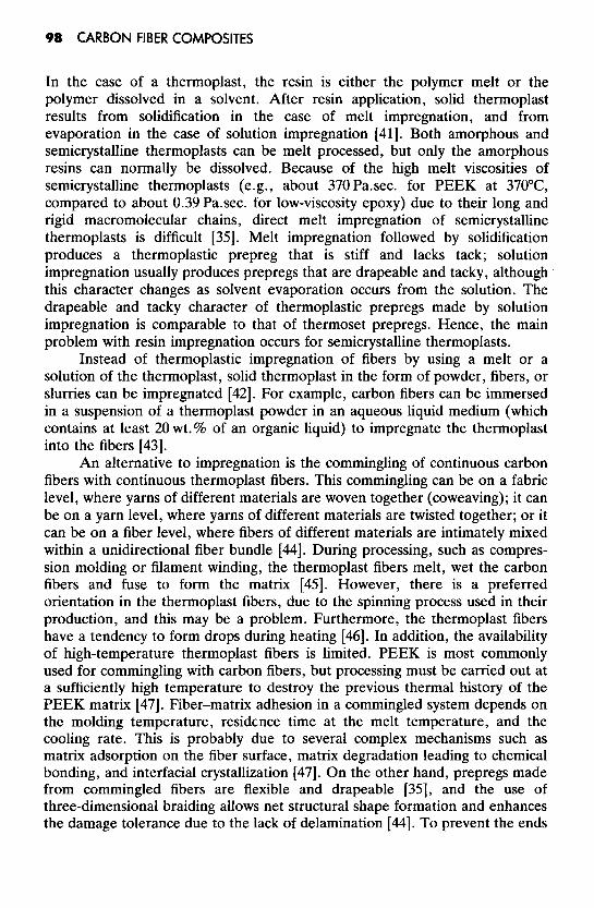
Figure 6.2 die-less forming. From Ref. 49.
Examples of singly curved and long components that can be fabricated by
of the braided preform from unbraiding, the thermoplast fibers are melted with a soldering gun before cutting, or alternately, the ends of the braided preform are wrapped with a polyimide tape and cut through the tape. The fiber commingling makes possible a uniform polymer distribution even when the three-dimensional preform is very large, although the heating time during consolidation needs to be longer for dense three-dimensional commingled fiber network braids than for unidirectional prepregs [44].
The shaping of thermoplast-matrix composite laminates can be performed by thermoforming in the form of matched-die forming [48] or die-less forming [49]. However, in addition to shaping, deformations in the form of transverse fiber flow (shear flow perpendicular to the fiber axis) and interply slip commonly occur, while intraply slip is less prevalent [48]. Die-less forming uses an adjustable array of universal, computer-controlled rollers to form an initially flat composite material into a long, singly curved part having one arbitrary cross-sectional shape at one end and another arbitrary shape at the other end, as illustrated in Figure 6.2. Heating and bending of the material are strictly local processes, occurring only within a small active forming zone at any one instant. The initially flat workpiece is translated back and forth along its length in a number of passes. On successive passes, successive portions of the transverse extent of the workpiece pass through the active forming region, as illustrated in Figure 6.3 [49]. Induction heating is used to provide the local heating in die-less forming, because it enables rapid, noncontact, localized and uniform through-thickness heating [50].
The schedule for variation of the temperature and pressure during curing and consolidation of prepregs to form a thermoset-matrix composite must be carefully controlled. Curing refers to the polymerization and cross-linking

100 CARBON FIBER COMPOSITES
Figure 6.3 Hatched areas are active forming regions. (Highly schematic and with an unrealistically large transverse increment per pass.) From Ref. 49.
Forming sequence in die-less forming of long and tapered components.
reactions that occur upon heating and lead to the polymer, whereas consolida- tion refers to the application of pressure to obtain proper fiber-matrix bonding, low void content, and the final shape of the part. Curing and consolidation are usually performed together as one process. For example, the curing and consolidation of a polyimide-matrix composite involves first heating without pressure at 220°C for 120 min., when melting and imidization occur, and then raising the temperature to 315"C, when the resin initially exhibits melt-flow behavior then solidification. Pressure is applied at the beginning of the 315°C heating stage [51].
The curing of a thermoset-matrix composite requires heat, which is usually obtained by resistance heating, though microwave heating is also possible [52]. An attraction of microwave heating is an increase in the amount of chemical interaction between the carbon fiber surface and the epoxy resin and amine components of the matrix [53].
For the thermoplast-matrix composites, increasing the cooling rate after lamination decreases the crystallinity of the polymer matrix. For cooling rates

Polymer-Matrix Composites 10 1
from l"F/min. to 1 000"F/min., a PEEK matrix in the presence of carbon fibers has a recrystallinity ranging from 45 to 30wt.%. Because the fibers act as nucleation sites for polymer crystallization when the polymer melt is sheared, the presence of fibers enhances the polymer crystallinity to a level above that of the neat polymer [54,55]. A greater crystallinity is associated with a higher level of fiber-matrix interaction [56]. The crystallinity can be increased by annealing at up to 310°C; the presence of carbon fibers accelerates the annealing effect [57].
Because of the high processing temperatures (up to 400°C) of high- temperature thermoplasts, traditional tooling materials are not very suitable. Instead of metal tooling materials, carbon fiber polyimide-matrix composites have successfully been used to fabricate parts from prepregs based on polyimide, PEEK, biomaleimides, etc. [58]. The advantages of the composite tooling lies in its low thermal expansion coefficient as well as its thermal stability.
Instead of using heat, thermoplast-matrix composites have been made by aqueous electrocopolymerization onto carbon fibers. An electropolymerization of 3-carboxyphenyl maleimide and styrene onto carbon fibers used dilute sulfuric acid and an aqueous solution containing monomers [59].
Short-fiber composites are formed by mill mixing the short fibers and the polymer powder or by dissolving the polymer in a solvent and forming a carbon fiber paste. The paste method causes less fiber breakage than the mill mixing method [60].
Carbon filaments (made from carbonaceous gases) are typically 0.1 pm in diameter, whereas carbon fibers are typically 10 pm in diameter. Thus, carbon filaments tend to cling together much more than carbon fibers. Consequently, the dispersion of carbon filaments is more difficult than that of carbon fibers. For the case of a thermoset matrix, the carbon filaments may be impregnated with the liquid resin, which subsequently sets; this process is not difficult. However, for the case of a thermoplast matrix, the thermoplast is usually in the form of particles, and the mixing of the thermoplast particles with the fine carbon filaments to achieve good filament dispersion may be difficult. A method to achieve filament dispersion in a thermoplast involves (1) dispersing the filaments in an alcohol aqueous solution with the help of a trace amount of a dispersant, (2) mixing the slurry with the thermoplast powder at room temperature by using a rotary blade blender to adjust the concentration of alcohol so that the thermoplast particles are suspended in the aqueous solution, (3) draining the solution, (4) drying, and (5) hot pressing above the Tg of the thermoplast. The mixing in step (2) causes very little filament breakage, so the aspect ratio of the filaments after mixing remains high (at least 1 OOO). After Step 4, a dry and uniform mixture of the thermoplast particles and the filaments is obtained in the form of clusters of size 0.1-0.5 mm. These clusters can be conveniently handled. They can be put into a die for hot pressing, (Step 5) , which results in a thermoplast-matrix composite [61].
102 CARBON FIBER COMPOSITES
Properties
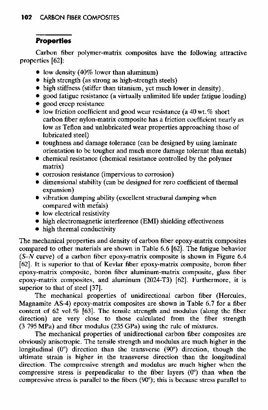
Carbon fiber polymer-matrix composites have the following attractive
low density (40% lower than aluminum) high strength (as strong as high-strength steels) high stiffness (stiffer than titanium, yet much lower in density).
0 good fatigue resistance (a virtually unlimited life under fatigue loading) 0 good creep resistance 0 low friction coefficient and good wear resistance (a 40 wt.% short
properties [62]:
carbon fiber nylon-matrix composite has a friction coefficient nearly as low as Teflon and unlubricated wear properties approaching those of lubricated steel) toughness and damage tolerance (can be designed by using laminate orientation to be tougher and much more damage tolerant than metals) chemical resistance (chemical resistance controlled by the polymer matrix)
0 corrosion resistance (impervious to corrosion) dimensional stability (can be designed for zero coefficient of thermal expansion)
0 vibration damping ability (excellent structural damping when compared with mecals)
0 low electrical resistivity 0 high electromagnetic interference (EMI) shielding effectiveness 0 high thermal conductivity
The mechanical properties and density of carbon fiber epoxy-matrix composites compared to other materials are shown in Table 6.6 [62]. The fatigue behavior (S-N curve) of a carbon fiber epoxy-matrix composite is shown in Figure 6.4 [62]. It is superior to that of Kevlar fiber epoxy-matrix composite, boron fiber epoxy-matrix composite, boron fiber aluminum-matrix composite, glass fiber epoxy-matrix composites, and aluminum (2024-T3) [62]. Furthermore, it is superior to that of steel [37].
The mechanical properties of unidirectional carbon fiber (Hercules, Magnamite AS-4) epoxy-matrix composites are shown in Table 6.7 for a fiber content of 62 vol.% [63]. The tensile strength and modulus (along the fiber direction) are very close to those calculated from the fiber strength (3 795 MPa) and fiber modulus (235 GPa) using the rule of mixtures.
The mechanical properties of unidirectional carbon fiber composites are obviously anisotropic. The tensile strength and modulus are much higher in the longitudinal (0") direction than the transverse (90") direction, though the ultimate strain is higher in the transverse direction than the longitudinal direction. The compressive strength and modulus are much higher when the compressive stress is perpendicular to the fiber layers (0") than when the compressive stress is parallel to the fibers (90"); this is because stress parallel to

Polymer-Matnx Composites 103
Table 6.6 Mechanical properties and density of unidirectional carbon fiber epoxy- matrix composite compared to other unidirectional epoxy-matrix composite materials and metals. From Ref. 62.
Strengtha (MPa)
Tensile modulus Density
Material Tension Compression (GPa) (glcm3)
Epoxy/carbon fibers AS-4 1482 1227 145 1.55 Epoxylcarbon fibers HMS 1276 1 020 207 1.63 Epoxy/S-2 glass fibers 1751 496 59 1.99 Epoxy/E-glass fibers 1103 490 52 1.99 EpoxyIAramid Kevlar 49 1310 290 83 1.39 Aluminum (7075-T6) 572 - 69 2.76 Titanium (6A1-4V) 1103 - 114 4.43 Steel (4130) 1241-1 379 - 207 8.01
aUnidirectional.
Figure 6.4 aluminum. From Ref. 62.
S-N curve to show the fatigue behavior of unidirectional composites and
104 CARBON FIBER COMPOSITES
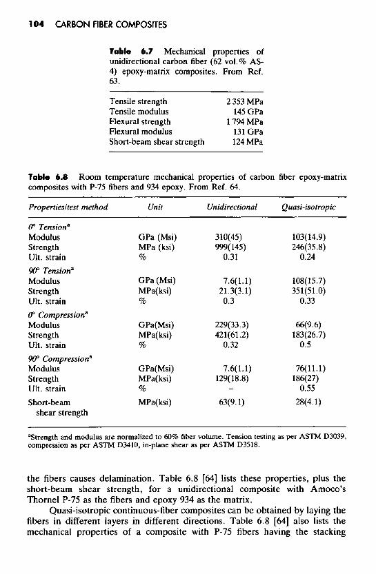
Table 6.7 Mechanical properties of unidirectional carbon fiber (62 vol.% AS- 4) epoxy-matrix composites. From Ref. 63.
Tensile strength 2 353 MPa Tensile modulus 145 GPa Flexural strength 1794 MPa Flexural modulus 131 GPa Short-beam shear strength 124 MPa
Table 6.8 composites with P-75 fibers and 934 epoxy. From Ref. 64.
Propertiesltest method Unit Unidirectional Quasi-isotropic
Room temperature mechanical properties of carbon fiber epoxy-matrix
(P Tensiona Modulus Strength Ult. strain 90" Tensiona Modulus Strength Ult. strain 0" Compression" Modulus Strength Ult. strain 90" Compressiona Modulus Strength Ult. strain Short-beam
shear strength
GPa (Msi) MPa (ksi) %
GPa (Msi) MPa( ksi) %
GPa(Msi) MPa(ksi) %
GPa(Msi) MPa( ksi) %
MPa( ksi)
310(45) 999( 145)
0.31
7.6(1.1) 21.3(3.1) 0.3
229(33.3) 421(61.2)
0.32
7.6(1 .l) 129( 18.8)
63(9.1)
-
103(14.9) 246( 35.8)
0.24
lOti(15.7) 35 l(5 1 .O)
0.33
66(9.6) 183(26.7)
0.5
76( 11 .l) 186(27)
0.55 28(4.1)
"Strength and modulus are normalized to 60% fiber volume. Tension testing as per ASTM D3039, compression as per ASTM D3410, in-plane shear as per ASTM D3518.
the fibers causes delamination. Table 6.8 [64] lists these properties, plus the short-beam shear strength, for a unidirectional composite with Amoco's Thornel P-75 as the fibers and epoxy 934 as the matrix.
Quasi-isotropic continuous-fiber composites can be obtained by laying the fibers in different layers in different directions. Table 6.8 [64] also lists the mechanical properties of a composite with P-75 fibers having the stacking

Polymer-Matrix Composites 105
Table 6.9 Properties of unidirectional carbon fiber (AS4-3K) thermoplast-matrix composites, with each composite having 10 plies of prepreg tape. From Ref. 65.
Matrix PEEK PPS ~ ~
Panel thickness per ply (mm) 0.13 0.14 Specific gravity 1.56 1.53 Fiber vol.% 60.0 56.2 Void vol. % 1.9 1.4 Flexural properties
Strength (MPa) 1687 1078 Modulus (GPa) 108 93.8
Transverse tensile strengtha (MPa) 91.0 15.2
Coefficient of thermal expansion ( 10-6/OC) H 2 0 absorption (wt. %) 0.15 0.20
-157 to 21°C 0.18 -1.1 21 to 121°C 0.49 0.18
Percent total mass loss 0.0348 0.0291 Percent collected volatile condensable materials 0.0054 0.0046
Outgassing
aASTM D3039-74.
sequence (00, 30", 60", W", 120", 150")s and with epoxy 934 as the matrix. The properties are indeed quasi-isotropic. The in-plane coefficient of thermal expansion of this composite is -0.16 X lO?"C [64].
The properties of unidirectional carbon fiber thermoplast-matrix (PEEK, PPS) composites are listed in Table 6.9 [65]. Comparison of Tables 6.9 and 6.7 show higher flexural strength and modulus for an epoxy-matrix composite than for a PEEK-matrix composite of similar fiber content and the same fiber type. On the other hand, the residual compressive strength after impact (CAI) of the PEEK-matrix composite is comparable to that of a toughened-epoxy-matrix composite and is superior to those of composites with standard epoxy or standard bismaleimide (BMI) matrices, as shown in Figure 6.5 [66]. The superior impact resistance of thermoplast-matrix composites compared t o thermoset-matrix composites makes thermoplast-matrix composites particularly attractive for aircraft applications. It should be mentioned that the mechanical properties of carbon fiber PEEK-matrix composites are influenced by the matrix crystallinity and the cooling rate, as shown in Table 6.10 for uni- directional carbon fibers (Hercules AS-4) [46].
The water absorption of the thermoplast-matrix composites is much lower than that of the epoxy-matrix counterpart (Figure 6.6). The equilibrium moisture levels are 0.15%, 0.20%, and 2.32% for PEEK-, PPS-, and epoxy-matrix composites, .respectively [65]. The outgassing amounts are comparable for composites of these three matrices and are all low enough to be acceptable for spacecraft applications.

106 CARBON FIBER COMPOSITES
Table 6.10 Effect of matrix crystallinity and cooling rate on the mechanical properties of unidirectional carbon fiber (AS-4) PEEK-matrix composites. From Ref. 46.
Flexural strength (MPa) Young’s ZLSS modulus
Crystallinity Cooling rate Longitudinal Transverse (MPa) (GPa)
High High 2 002 146 101 111.1 High L O W 2 066 114 103 101.6 Low High 2 162 169 107 106.4 Low Low 2 426 131 108 128.0
Figure 6.5 carbon fiber composites with various polymer matrices. From Ref. 66. (Reprinted by permission of Kluwer Academic Publishers.)
Residual compressive strength after impact versus impact energy for
Figure 6.6 composites with epoxy and thermoplasts (PEEK and PPS) as matrices. From Ref. 65. (Reprinted by permission of the Society for the Advancement of Material and Process Engineering.)
Water absorption at 160°F (71°C) for carbon fiber polymer-matrix

Polymer-Matrix Composites 1 07
Table 6.1 1 composites. From Ref. 67
Reinforcement dimensionality Strength (MPa) Modulus (GPa) Fracture straina (%)
Transverse (f45") tensile properties of carbon fiber PEEK-matrix
1 2 3
309 7.72 255 8.00 155 8.34
26 14 7.0
aMeasured by crosshead travel.
Table 6.9 shows a higher transverse tensile strength for the PEEK-matrix composite than the PPS-matrix composite. This is because of the stronger fiber-matrix adhesion in the former. The stronger fiber-matrix adhesion for PEEK is due to the higher crystallinity in PEEK than PPS [65].
The transverse (f45") tensile properties of PEEK composites containing unidirectional carbon fiber tape, two-dimensional fabric, and three-dimensional fabric are shown in Table 6.11 [67]. Both the strength and fracture strain decrease with increasing dimensionality, whereas the modulus does not vary much with dimensionality.
The use of carbon fiber polymer-matrix composites for primary structural applications requires high compressive strength after impact damage (CAI) and high compressive strength at elevated temperatures after exposure to wet environments (CHW). These properties depend on the toughness of the matrix resin. Methods to improve the matrix toughness include the following [68]:
0 using an epoxy resin of high elongation 0 blending an elastomer with the epoxy resin
blending a thermoplastic with the epoxy resin 0 introducing a discrete interleaf layer between prepreg layers in the
0 using a tough thermoplastic matrix laminate
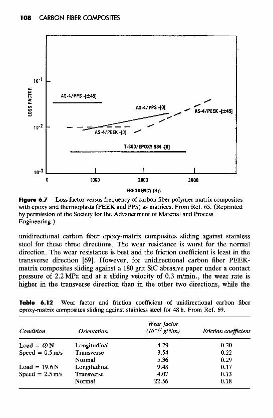
The damping ability of a fibrous composite improves as the fiber-matrix bonding weakens. Figure 6.7 [65] shows that the damping ability (loss factor) increases in the order: epoxy, PEEK, PPS.
The wear resistance and friction coefficient of carbon fiber polymer- matrix composites depend on the sliding direction with respect to the fiber direction. For unidirectional fiber composites, the fibers can be in the plane of sliding and parallel to the direction of sliding (termed longitudinal); they can be in the plane of sliding and perpendicular to the direction of sliding (termed transverse); they can stand normal to the plane of sliding (termed normal). Table 6.12 shows the wear factors and friction coefficients of high-modulus
108 CARBON FIBER COMPOSITES
Figure 6.7 Loss factor versus frequency of carbon fiber polymer-matrix composites with epoxy and thermoplasts (PEEK and PPS) as matrices. From Ref. 65. (Reprinted by permission of the Society for the Advancement of Material and Process Engineering.)
unidirectional carbon fiber epoxy-matrix composites sliding against stainless steel for these three directions. The wear resistance is worst for the normal direction. The wear resistance is best and the friction coefficient is least in the transverse direction [69]. However, for unidirectional carbon fiber PEEK- matrix composites sliding against a 180 grit S i c abrasive paper under a contact pressure of 2.2 MPa and at a sliding velocity of 0.3 dmin . , the wear rate is higher in the transverse direction than in the other two directions, while the
Table 6.1 2 Wear factor and friction coefficient of unidirectional carbon fiber epoxy-matrix composites sliding against stainless steel for 48 h. From Ref. 69.
Wear factor Condition Orientation (IO-" glNm) Friction coefficient
Load = 49N Longitudinal 4.79 0.30
Normal 5.36 0.29 Load = 19.6N Longitudinal 9.48 0.17 Speed = 2.5 d s Transverse 4.07 0.13
Normal 22.56 0.18
Speed = 0.5 m / s Transverse 3.54 0.22

Polymer-Matrix Composites 109
friction coefficient is essentially independent of the sliding direction [70]. In general, carbon fibers improve the wear resistance of polymers; this is because of the strengthening due to the fibers and, in the case of high-modulus carbon fiber composites, because the composite generates a surface wear film, which reduces friction and wear owing to the self-lubricating nature of the graphite debris. Both unreinforced PEEK and a carbon fiber PEEK-matrix composite display a relative minimum in wear against mild steel at a certain level of counterface roughness, but the minimum for the composite occurs at a greater counterface roughness than the minimum for the unreinforced PEEK [71].
The plastic memory phenomenon is the tendency of a thermoplastic material that has been deformed above Tg to return to its original shape upon reheating above Tg. The origin of this phenomenon probably is related to the fact that the potential energy, which the polymer chains contain in the deformed shape (in the glassy solid phase), is released when the specimen is reheated into the rubbery phase. The polymer chains probably dissipate their stored energy by relative movement, eventually reaching their lowest energy configuration corresponding to the specimen’s originally molded shape. This phenomenon is exhibited not only by the neat thermoplast, but also by thermoplasts, PEEK and polybutylene teraphthalate (PBT), reinforced by continuous or short carbon fibers, though the use of neat thermoplast laminae in addition to the carbon fiber prepreg laminae markedly improves the shape recovery. The plastic memory phenomenon is potentially useful for self- deploying of space structures such as antenna reflectors [72].
The high thermal conductivity of carbon fibers, especially the high modulus pitch-based fibers (Amoco’s Thornel P-100 and P-120, with fiber thermal conductivity at 300 K of 300 and 520 W/m/K, respectively) and the vapor grown carbon fibers (with fiber thermal conductivity at 300K of 1 380 W/m/K), makes these fibers highly effective for increasing the thermal conductivity of polymers. Table 6.13 shows the 300 K thermal conductivity and the thermal conductivity/density ratio of various unidirectional carbon fiber polymer-matrix composites, together with the corresponding values of metals. The highest thermal conductivity at 245 W/m/K is associated with the P-120 fibers. This conductivity value is higher than that of aluminum, though lower than that of copper. The ratio of the thermal conductivity to the density is higher than that of aluminum for composites with P-120 or P-100 fibers in the amount of 45 vol.%. The combination of high thermal conductivity, low density, and good corrosion resistance makes these composites valuable for aerospace structures, electronic packaging, and many other applications [73]. One disadvantage of using P-100, P-120, or other graphitic carbon fibers of high thermal conductivity is that they cause the polymer-matrix composite to be so low in thermal expansion that CTE mismatch occurs between the composite and its neighbor (e.g., a printed circuit board). In order to alleviate this problem, metal-coated carbon fibers are used [74].
If high-strength carbon fibers rather than high-modulus carbon fibers are used, the thermal conductivity of the composites are lower. Figures 6.8 and 6.9

110 CARBON FIBER COMPOSITES
Table 6.13 copper and aluminum. From Ref. 73.
Thermal conductivities ( K ) of the composites compared with those of
Fiber Density K3WK K300K/density Sample Fibers Matrix (%) (kglm3) (WImIK) (W.m21kglK)
#3 #4 #5 #6 #8 #9
#10 #11 Pure copper Pure aluminum Stainless steel
P-75 P-75 P-100 P- 100 P-75 P-75 P-100 P-120
Polystyrene Polystyrene Polystyrene Polyester Polyester Polyester Polyester Polyester
35 1340 59.8 30 1290 30.1 30 1340 95.4 15 1370 60.0 29 1450 45.8 45 1580 64.5 45 1640 140.4 45 1660 245.0
8960 450.0 2700 200.0 7 860 15.0
0.045 0.023 0.072 0.044 0.032 0.042 0.088 0.148 0.050 0.074 0.002
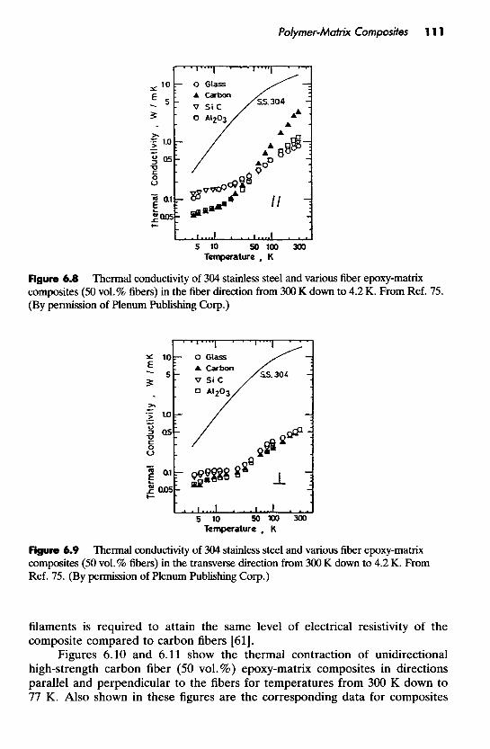
show the thermal conductivities of unidirectional high-strength carbon fiber (50 vol. %) epoxy-matrix composites in directions parallel and perpendicular to the fibers for temperatures from 300 K down to 4.2 K. Also shown in Figure 6.8 are the corresponding data for unidirectional epoxy-matrix composites with 50 vol.% glass fibers, 50 vol.% Sic fibers, and 50 vol.% A1203 fibers. In the direction parallel to the fibers (Figure 6.8), the carbon fiber composite has thermal conductivity that is higher than the other three composites at temperatures above 40 K, but has thermal conductivity that is lower than glass and Sic fiber composites and comparable to the AZO3 fiber composite at temperatures below 40K; in particular, at 300K the thermal conductivity of the carbon fiber composite is about four times as much as that of the glass fiber composite. In the direction perpendicular to the fibers (Figure 6.9), the thermal conductivities of all four fiber composites are similar for the whole temperature range from 300 K down to 4.2 K, so the thermal conductivity in this direction is dominated by the epoxy matrix. Comparison of Figures 6.8 and 6.9 shows that the thermal conductivity in the direction perpendicular to the fibers is lower than that in the direction parallel to the fibers for all four types of fiber composite [75].
Short carbon fibers are commonly used as an electrically conductive filler for polymers used for electromagnetic interference shielding, antistatic, and other electronic applications. Due to their small diameter, short carbon filaments tend to have a larger aspect ratio than short carbon fibers. As a result, short carbon filaments tend to be more effective at providing electrically conductive polymer-matrix composites than comparably short carbon fibers of similar electrical resistivity. This means that a lower volume fraction of carbon
Polymer-Matnx Composites 11 1
Figure 6.8 composites (50 vol.% fibers) in the fiber direction from 300 K down to 4.2 K. From Ref. 75. (By permission of Plenum Publishing Corp.)
Thermal conductivity of 304 stainless steel and various fiber epoxy-matrix
Figure 6.9 composites (50 vol.% fibers) in the transverse direction from 300 K down to 4.2 K. From Ref. 75. (By permission of Plenum Publishing Corp.)
Thermal conductivity of 304 stainless steel and various fiber epoxy-matrix
filaments is required to attain the same level of electrical resistivity of the composite compared to carbon fibers [61].
Figures 6.10 and 6.11 show the thermal contraction of unidirectional high-strength carbon fiber (50 vol. %) epoxy-matrix composites in directions parallel and perpendicular to the fibers for temperatures from 300 K down to 77 K. Also shown in these figures are the corresponding data for composites

1 12 CARBON FIBER COMPOSITES
Figure 6.10 Thermal contraction of various fiber epoxy-matrix composites (50 vol.% fibers) in the fiber direction from 300 K down to 77 K. From Ref. 75. (By permission of Plenum Publishing Corp.)
Figure 6.1 1 fibers) in the transverse direction from 300 K down to 77 K. From Ref. 75. (By permission of Plenum Publishing C o p )
with glass, Sic and A1203 fibers instead of carbon fibers. In the direction parallel to the fibers (Figure 6.10), the thermal contraction is lowest for the carbon fiber composite, which has a thermal contraction of 0.015% at 77 K. In the direction perpendicular to the fibers (Figure 6. 11), the thermal contraction is much larger than in the direction parallel to the fibers and is similar for all four fiber types [75].
The cryogenic properties of carbon fiber composites are relevant to the
Thermal contraction of various fiber epoxy-matrix composites (50 vol.%

Polymer-Matrix Composites 1 13
application as cryogenic structural support members. This application is made possible by the fact that the strength and modulus of the composites increase with decreasing temperature [75,76].
The low electrical resistivity and high aspect ratio of short carbon fibers make them very effective as a filler for making electrically conducting polymer-matrix composites, which are useful for electromagnetic interference (EMI) shielding [77] and, in the case of pressure-sensitive conductive rubber composites, for touch control switches and strain sensors [78]. For electrically conducting polymer-matrix composites with a discontinuous filler (which allows injection molding and related composite fabrication methods), short carbon fibers compete with carbon black as the filler. Due to the high aspect ratio of short carbon fibers compared to carbon black, the required critical filler volume fraction is lower for short carbon fibers than carbon black. However, for the case of rubber as the matrix, due to the stronger filler-matrix interaction for carbon black as the filler, the mechanical properties are superior for composites containing carbon black [79]. The EM1 shielding effectiveness and electrical conductivity of carbon fiber polymer-matrix composites increase with increasing fiber content and decrease with increasing frequency [77,80]. The frequency dependence of the AC conductivity (with the electric field parallel to the fibers) is due to the reactance increase associated with the magnetic flux change from neighboring fibers [SO]. For pressure-sensitive conductive rubber composites, the electrical conductivity increases but the pressure sensitivity decreases when the fibers are oriented along the longitudin- al direction with respect to the electric field, whereas the electrical conductivity decreases but the pressure sensitivity increases when the fibers are transversely oriented [78]. The electrical conductivity and EM1 shielding effectiveness can be enhanced by using nickel-coated carbon fibers [81]. Nickel is more commonly used than copper for the coating because of the superior oxidation resistance of nickel.
Degradation
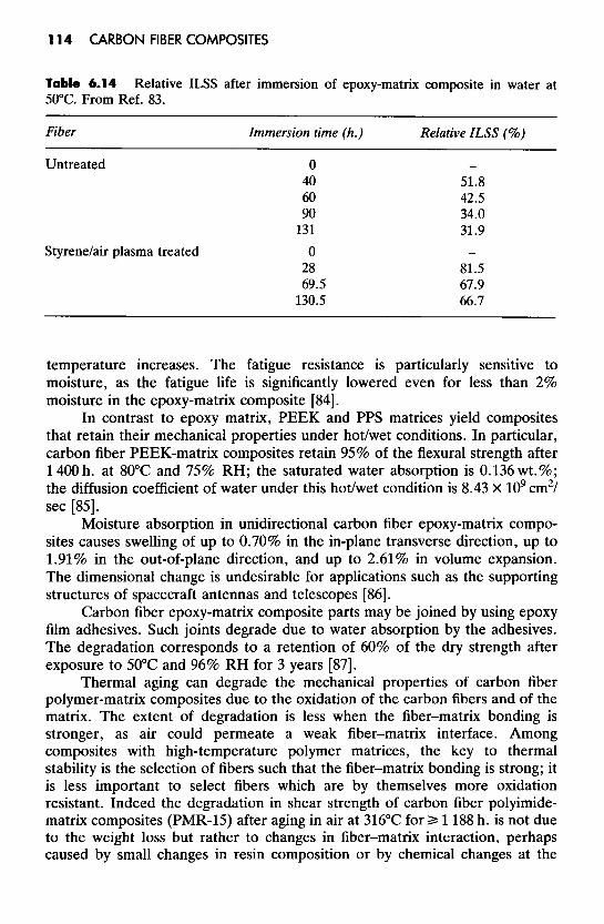
The degradation of carbon fiber polymer-matrix composites under hygrothermal environments causes deterioration of the mechanical properties. This is mostly due to a decrease in the fiber-matrix adhesion. For unidirection- al carbon fiber epoxy-matrix composites, the mechanical property deterioration is in terms of the transverse properties (transverse modulus, ILSS, etc.) rather than the longitudinal properties [82]. Table 6.14 [83] shows the relative ILSS (i.e., the ratio of the wet ILSS to the dry ILSS) as a function of time of immersion in water at 50°C for untreated carbon fiber and styrene/air plasma-treated fiber in an epoxy matrix. The degradation is particularly fast during the first hour of water immersion. Beyond 1 h., the degradation continues, but more slowly. The nearly stabilized state of degradation corresponds to a relative ILSS of 32% for the untreated fiber and 67% for the plasma-treated fiber [83]. The deterioration becomes more severe as the
114 CARBON FIBER COMPOSITES
Table 6.14 50°C. From Ref. 83.
Fiber Immersion time (h.) Relative ILSS (%)
Relative ILSS after immersion of epoxy-matrix composite in water at
Untreated
Styrenelair plasma treated
0 40 60 90
131 0
28 69.5
130.5
51.8 42.5 34.0 31.9
81.5 67.9 66.7
temperature increases. The fatigue resistance is particularly sensitive to moisture, as the fatigue life is significantly lowered even for less than 2% moisture in the epoxy-matrix composite [84].
In contrast to epoxy matrix, PEEK and PPS matrices yield composites that retain their mechanical properties under hot/wet conditions. In particular, carbon fiber PEEK-matrix composites retain 95% of the flexural strength after 1 400 h. at 80°C and 75% RH; the saturated water absorption is 0.136 wt.%; the diffusion coefficient of water under this hot/wet condition is 8.43 X lo9 cm2/ sec [85].
Moisture absorption in unidirectional carbon fiber epoxy-matrix compo- sites causes swelling of up to 0.70% in the in-plane transverse direction, up to 1.91% in the out-of-plane direction, and up to 2.61% in volume expansion. The dimensional change is undesirable for applications such as the supporting structures of spacecraft antennas and telescopes [86].
Carbon fiber epoxy-matrix composite parts may be joined by using epoxy film adhesives. Such joints degrade due to water absorption by the adhesives. The degradation corresponds to a retention of 60% of the dry strength after exposure to 50°C and 96% RH for 3 years [87].
Thermal aging can degrade the mechanical properties of carbon fiber polymer-matrix composites due to the oxidation of the carbon fibers and of the matrix. The extent of degradation is less when the fiber-matrix bonding is stronger, as air could permeate a weak fiber-matrix interface. Among composites with high-temperature polymer matrices, the key to thermal stability is the selection of fibers such that the fiber-matrix bonding is strong; it is less important to select fibers which are by themselves more oxidation resistant. Indeed the degradation in shear strength of carbon fiber polyimide- matrix composites (PMR-15) after aging in air at 316°C f o r b 1 188 h. is not due to the weight loss but rather to changes in fiber-matrix interaction, perhaps caused by small changes in resin composition or by chemical changes at the

Polymer-Matrix Composites 1 15
fiber-matrix interface [88]. Moreover, the activation energy of oxidation of the composite is greater than those of the fibers and the matrix, indicating a synergistic effect from the fiber-matrix combination [89]. By using N- phenylnadimide-modified PMR-15 polyimide and Celion 6OOO carbon fibers, composites that can be used for 100 h. under continuous heating at 371°C in air have been reported. The superior thermal stability of the modified PMR-15 composite compared to the counterpart without modification is attributed to the higher residual stress in the latter due to the greater cross-link density [%I. For PEEK and BMI as matrices, it has been reported that uni- directional carbon fiber composites have higher percentage retentions of ILSS and impact strength than the multidirectional counterpart after thermal aging in air at 190°C for up to 1 OOO h. [91].
Thermal spikes from 20°C to 150°C (as can be produced in the outer skins of supersonic aircraft) decrease considerably the fatigue life of carbon fiber epoxy-matrix composites, even when no damage is observed by optical microscopy [92]. Impact at ultrahigh strain rates of about 107/sec., as obtained by short pulsed laser induced shock waves, cause spall damage in carbon fiber epoxy-matrix composites at a threshold pressure of 1.5 kbar, compared to 21 kbar for aluminum and 54 kbar for iron [93].
Carbon fiber polymer-matrix composites give rise to galvanic corrosion when they are in contact with metals (other than platinum, gold, and titanium) which get corroded because the carbon fibers serve as the cathode. When the composite is in seawater, aragonite crystal (a form of calcium carbonate) grows on the composite, causing blistering. Due to the common use of metals as substructures and fasteners in systems in the ocean, this problem is frequently encountered [94].
High-energy radiation encountered by composites used for space satellites in geosynchronous orbit can cause degradation due to the molecular scissions in the polymer matrix. This problem can be alleviated by the incorporation of radiation-resistant groups into the polymer [95].
Joining and Repair The joining and repair of composite parts are closely related, as joining is
usually involved in repair. Joining methods differ greatly between thermoset- and thermoplast-matrix composites.
Thermoset-matrix composites are commonly joined by using an adhesive film, such as epoxy, though the joint strength is low. Mechanical fastening is sometimes used, but it is difficult because the drilling of holes in the brittle composite causes weakness and even damage, and the metals used as screws cause thermal expansion mismatches and induce galvanic corrosion due to the cathodic nature of carbon. Thus, the joining of thermoset-matrix composites is an area which needs further work.
Thermoplast-matrix composites are commonly joined by fusion welding, which means heating to cause flow between the thermoplast parts. As the

116 CARBON FIBER COMPOSITES
temperatures involved are much lower than those required for the fusion welding of metals, the techniques of thermoplast welding differ from those of metal welding. The techniques of thermoplast fusion welding include electrical resistance heating, focused infrared heating, vibration (ultrasonic) welding, the heated press technique and thermoplastic interlayer bonding. In general, the joining techniques utilize heat to melt either the matrix resin or an unrein- forced thermoplastic film placed between the parts to be joined. The interlayer (interleaf) can be a 100pm thick film of amorphous PEEK [96] or amorphous polyetherimide (PEI) [97], in the case of joining PEEK-matrix composite parts. Lap shear joint strengths in excess of 50 MPa have been achieved; most successful was the heated press technique [96]. The fusion welding methods are rapid (5 min.) compared to the use of an epoxy film adhesive (1 h.) [97].
The repair of damaged carbon fiber thermoplast-matrix composites can be achieved by hot pressing at the usual molding temperature for the thermoplast. For PEEK as the thermoplast matrix, delamination-type fracture such as that incurred at low incident energies can be fully repaired without any loss in mechanical integrity. However, in the case of extensive fiber fracture (as incurred at energies of 12 J or more), the success of the repair is not total, though the residual compressive and flexural strengths of the repaired specimen are still considerably greater than those of the as-impacted specimen [981.
Inspection
The inspection of fiber composite parts is mainly for observing the fiber arrangement and defects, as such structural features strongly affect the properties of the composites. Defects include the following [99]:
matrix cracks (voids, porosities) fiber cracks interface cracks (debonding) delamination (splitting between laminae and a laminate) inclusions (foreign bodies in the composite)
Techniques for inspection include metallography (microscopy of polished surfaces) , transmission microscopy of thin sections, low-voltage radiography with soft X-rays [99], infrared thermal imaging and the C-scan technique [98]. The infrared technique makes use of the thermally conductive nature of carbon fibers, but it is mostly limited to continuous fiber laminates [lOO].
Carbon fiber polymer-matrix composites are predominantly used for the aerospace industry, but the decreasing price of carbon fibers is widening the applications of these composites to include the automobile, marine, sports, biomedical, construction, and other industries.

Polymer-Matrix Composites 1 17
One area of aerospace applications is space vehicles. The United States Space Shuttle uses carbon fiber epoxy-matrix composites for its payload bay door and remote manipulator arm [loll; its solid rocket motor cases also use epoxy-matrix composites; its booster tail and fins use polyimide-matrix composites. Satellite structures [102-1041 and solar panels also use carbon fiber polymer-matrix composites. Most space applications utilize standard aerospace grade carbon fibers (tensile strength 3 550 MPa, tensile modulus 235 GPa) combined with a 177°C cure multifunctional epoxy resin matrix. Filament wound rocket motor cases employ a 121°C cure, modified bis-A-epoxy as the resin matrix. Stiffness requirements of some satellite applications dictate the use of high-modulus carbon fibers (350 GPa) [ 1051. Thermoplast matrices such as PEEK [lo61 and PES [lo71 are gaining attention for space applications.
A second area is military aircraft. Examples include Gripen, EFA, French Rafale, and U.S. B-2, which use the 177°C cure toughened thermoset matrix resins along with intermediate-modulus (295 GPa), or high-strength (5 590 MPa), intermediate-modulus carbon fibers. The U.S. Advanced Tactical Fighter is planned to use thermoplastics or toughened bismaleimide as a primary structural material. Older military aircraft are being modified with epoxy-matrix composite wings [ 1051.
Helicopters are a third area, both for military and commercial use. For example, the all-composite MBB BK117 helicopter is two-thirds carbon fiber epoxy-matrix composite, one-third aramid fiber and glass fiber epoxy-matrix composite. Both 121°C and 177°C cure epoxy resins are used [105].
A fourth area is concerned with primary and secondary structures in commercial aircraft [ 1081. Examples of primary structural applications include the Airbus A310/A320 vertical tail fin boxes (121°C cure toughened epoxy), the A320 horizontal tail fin (177°C cure epoxy) [lo81 and the ATR 72 external wing box (177°C toughened epoxy) [ 1051.
A fifth area of aerospace applications is commercial aircraft engines. Outer and front sections of the engine are subjected to lower temperatures and can utilize an epoxy matrix. For example, the front fan ducts on Rolls-Royce engines and the blocker doors and transcowls on General Electric’s CF6-8OC2 engines use 177°C cure epoxy. Engine rear section components operate at higher temperatures; this necessitates polyimide matrices such as PMR-15, which is used for thrust reversers and bypass ducts. Thermoplasts such as PEEK are being considered for engine applications [ 1051.
Aluminum is a lightweight metal that competes with carbon fiber polymer-matrix composites for aerospace applications. In addition to their much higher strength and modulus, the carbon fiber composites are produced using much less energy and costly pollution control compared to aluminum [ 1091.
Carbon fiber polymer-matrix composites have started to be used in automobiles mainly for saving weight (Le., fuel economy). The so-called graphite car employs carbon fiber epoxy-matrix composites for body panels, structural members, bumpers, wheels, drive shaft, engine components, and

118 CARBON FIBER COMPOSITES
suspension systems [110,111]. This car is 1 250 lb. (570 kg) lighter than an equivalent vehicle made of steel. It weighs only 2 7501b. instead of the conventional 4 000lb. for the average American car [110]. Thermoplastic composites with PEEK and polycarbonate (PC) matrices are finding use as spring elements for car suspension systems [ 1121.
The electrically conductive characteristic of carbon fiber polymer-matrix composites makes them suitable for static dissipation (which requires an electrical resistivity of 104-106 R.cm), functional elements in high-impedance circuits (which require a resistivity of 102-103R.cm), and shielding from radio frequency interference (which requires a resistivity of 10'-lo2 R.cm). From loadings as low as 10 wt.%, a polymer is made static-dissipating, protecting electronic circuits or avoiding spark generation [113]. In addition, carbon fiber polymer-matrix composites are used for RF components [114]. The protection of aircraft from lightning damage is a related application [115,116]. The electrically conductive characteristic also makes carbon fiber polymer-matrix composites useful as electrodes [117,118].
The high thermal conductivity and low thermal expansion of continuous carbon fiber polymer-matrix composites make them suitable for heat sinks in electronics [119]. Since a heat sink is in contact with a ceramic chip carrier or a printed circuit board, a low thermal expansion is preferred. The low density of the composites (compared to copper) makes them even more attractive for aerospace electronics [120].
The X-ray transparency of carbon fibers makes carbon fiber polymer- matrix composites useful for passing small-impulse electric currents to monitor a patient's vital signs while he is being X-rayed [121].
Thermoplasts filled with short or continuous carbon fibers are useful as bone plates for fracture fixation. Metal bone plates suffer from metallic ion leaching, which may cause adverse local tissue reactions and even local tumor formation, and from stress protection atrophy. Polylactic acid (PLA) is an absorbable thermoplast used for this application, but its mechanical properties are not sufficient for long bone fixation, so continuous carbon fibers are added to produce a semiabsorbable composite [122]. Polymers, such as PEEK, which are not absorbable are also used for this application [123].
Due to the concern about the loss of bone around stiff metallic femoral stems, more flexible carbon fiber polymer-matrix composites are being considered for use in hip replacement prostheses [ 1241.
Continuous carbon fiber polymer-matrix composites are replacing steel for reinforcing concrete structures, because the composites are lightweight, available in continuous and long lengths, and do not rust. The lightweight characteristic makes them convenient to install [125,126].
Continuous carbon fiber polymer-matrix composites are used as acoustic diaphragms in speakers and microphones because of their low weight, high elasticity, fast sound transmission velocity, and excellent rigidity. These diaphragms exhibit less deformation due to an external force, a small sound

Polymer-Matrix Composites 1 19
distortion, wide sound reproduction range, distinct sound quality, and are suitable for digital audio applications [127].
Short carbon fibers, together with graphite powder, in a polyimide matrix provide an abrasion-resistant material that is useful for bearings [128].
Short carbon fibers in a polyurethane resin or its precursor provide a sealing compound with a high tensile strength for use in filling and sealing a gap between two parts [ 1291.
References 1. W.-T. Whang and W.-L. Liu, SAMPE Q. 22(1), 3-9 (1990). 2. D.C. Sherman, C.-Y. Chen, and J.L. Cercena, in Proc. Int. SAMPE Symp.
and Exhib., 33, Materials: Pathway to the Future, edited by G. Camllo, E.D. Newell, W.D. Brown, and P. Phelan, 1988, pp. 134-145.
Kent, 1989, pp. 538-539.
20th Int. SAMPE Tech. Conf., 1988, pp. 26S270.
3. D.R. Askeland, The Science and Engineering of Materiuls, 2nd ed., PWS-
4. S.D. Mills, D.M. Lee, A.Y. Lou, D.F. Register, and M.L. Stone, in Proc.
5. S. Wang and A. Garton, Polym. Mater. Sci. Eng. 62, 900-902 (1990). 6. T.E. Twardowski and P.H. Geil, J. Appl. Polym. Sci. 42(6), 1721-1726
7. H.G. Recker, SAMPE J. 26(2), 73-78 (1990). 8. W.D. Bascom, Polym. Mater. Sci. Eng. 63, 676-680 (1990). 9. R.B. Gosnell, in Proc. Int. SAMPE Symp. and Exhib., 33, Materials:
Pathway to the Future, edited by G. Carrillo, E.D. Newell, W.D. Brown, and P. Phelan, 1988, pp. 746-753.
10. R.D. Vannucci, D. Malarik, D. Papadopoulos, and J. Waters, in Proc. Int. SAMPE Tech. Conf , 22, Advanced Materials: Looking Ahead to the 21st Century, edited by L.D. Michelove, R.P. Caruso, P. Adams, and W.H. Fossey, Jr., 1990, pp. 175-185.
11. Z. Qusen, L. Yuhua, C. Zhenghua, and S. Dongsheng, MD, 5(Adv. Compos. Process. Technol.), 27-32 (1988).
12. R.J. Morgan, R. Jurek, D.E. Larive, C.M. Tung, and T. Donnellan, Polym. Mater. Sci. Eng. 63, 681-685 (1990).
13. M.S.M. Alger and R.W. Dyson, Engineering Polymers, edited by R.W. Dyson, Blackie, Glasgow, 1990, pp. 1-28.
14. R.E. Allred and L.A. Harrah, in Proc. Int. SAMPE Symp. and Exhib., 34, Tomorrow’s Materials: Today, edited by G.A. Zakrzewski, D. Mazenko, S.T. Peters, and C.D. Dean, 1989, pp. 2559-2568.
15. W.W. Wright, Compos. Polym. 3(4), 231-257 (1990). 16. P.W. Yip and S.S. Lin, in Mater. Res. SOC. Symp. Proc., Vol. 170, Interfaces
Compos., edited by C.G. Pantano and E.J.H. Chen, 1990, pp. 339-344. 17. T.C. Chang and B.Z. Jang, in Mater. Res. SOC. Symp. Proc., Vol. 170
Interfaces Compos., edited by C.G. Pantano and E.J.H. Chen, 1990, pp.
18. T.R. King, D.F. Adams, and D.A. Buttry, Composites 22(5), 380-387
19. M.J. Rich and L.T. Drzal, J . Reinf. Plast. Compos. 7(2), 145-154 (1988). 20. B.-W. Chun, C.R. Davis, Q. He and R.R. Gustafson, Carbon 30(2),
(1991).
321-326.
(1991).
177-187 (1992).

120 CARBON FIBER COMPOSITES
21. L.T. Drzal, Vacuum 41(7-9), 1615-1618 (1990). 22. Adhesion and Bonding in Composites, edited by R. Yosomiya, K.
Morimoto, A. Nakajima, Y. Ikada, and T. Suzuki, Marcel Dekker, New York, 1990, pp. 257-281. (Chapter on Interfacial Effect of Carbon-Fiber- Reinforced Composite Material.)
23. Adhesion and Bonding in Composites, edited by R. Yosomiya, K. Morimoto, A. Nakajima, Y. Ikada, and T. Suzuki, Marcel Dekker, New York, 1990, pp. 109-154. (Chapter on Modification of Inorganic Fillers for Composite Materials.)
24. G. Sugerman, S.M. Gabayson, W.E. Chitwood, and S.J. Monte, in Proc. 3rd Dev. Sci. Technol. Compos. Mater., Eur. Conf. Compos. Mater., edited by A.R. Bunsell, P. Lamicq, and A. Massiah, Elsevier, London, U.K.,
25. K.T. Kern, E.R. Long, Jr., S.A.T. Long, and W.L. Harries, Polym. Prepr.
26. W.W. Wright, Compos. Polym. 3(5), 360-401 (1990). 27. R.V. Subramanian, A.R. Sanadi, and A. Crasto, J . Adhes. Sci. Technol.
4(10), 329-346 (1990). 28. S.H. Jao and F.J. McGarry, in Proc. Int. SAMPE Tech. Conf., 22,
Advanced Materials: Looking Ahead to the 21st Century, edited by L.D. Michelove, R.P. Caruso, P. Adams, and W.H. Fossey, Jr., 1990, pp. 455-469.
29. C. Sellitti, J.L. Koenig, and H. Ishida, Mater. Sci. Eng. A126, 235-244 (1990).
30. B. Barbier, J. Pinson, G. Desarmot, and M. Sanchez, J . Electrochem. SOC.
31. L.T. Drzal, Mater. Sci. Eng. A126, 289-293 (1990). 32. L.T. Drzal, Mater. Res. SOC. Symp. Proc. Vol. 170, Interfaces Compos.,
edited by C.G. Pantano and E.J.H. Chen, 1990, pp. 275-283. 33. L.T. Drzal, Treatise on Adheswn and Adhesives, Vol. 6, edited by R.L. Patrick,
Marcel Dekker: New York, 1989, pp. 187-211. 34. N.C. W. Judd, Br. Polym. J . 9(4), 272-277 (1977). 35. P.J. Ives, and D.J. Williams, in Proc. Int. SAMPE Symp. and Exhib., 33,
Materials: Pathway to the Future, edited by G. Carrillo, E.D. Newell, W.D. Brown, and P. Phelan, 1988, pp. 858-869.
36. G.M. Knoblach, in Proc. Int. SAMPE Symp. and Exhib. 34, Tomorrow’s Materials: Today, edited by G.A. Zakrzewski, D. Mazenko, S.T. Peters, and C.D. Dean, 1989, pp. 385-396.
37. E. Fitzer, in Carbon Fibers Filaments and Composites, edited by J.L. Figueiredo, C.A. Bernardo, R.T.K. Baker, and K.H. Huttinger, Kluwer Academic, Dordrecht, 1990, pp. 169-219.
38. W.R. Stabler, G.B. Tatterson, R.L. Sadler, and A.H.M. El-Shiekh, SAMPE Q. 23(2), 38 (1992).
39. K.C. Ik and K.U. Gon, in Proc. 7th Int. Conf. on Composite Materials, Guangzhou, China, Nov. 1989, Vol. 2 , edited by Y. Wu, Z.-L. Gu, and R. Wu, International Academic Publishers, Beijing, P.R. China, and Perga- mon, Oxford, U.K. and New York, 1989, pp. 101-109.
40. 0. Dickman, K. Lindersson, and L. Svensson, Plastics and Rubber Processing and Applications 13, 9-14 (1990).
41. S.D. Copeland, J.C. Seferis, and M. Carrega, J. Appl. Polym. Sci. 44(1),
42. T. Hartness, in Proc. Znt. SAMPE Symp. and Exhib., 33, Materials: Pathway to the Future, edited by G. Carrillo, E.D. Newell, W.D. Brown, and P. Phelan, 1988, pp. 1458-1471.
1989, pp. 51-56.
(Am. Chem. SOC., Div. Polym. Chem.) 31(1), 611-612 (1990).
137(6), 1757-1764 (1990).
41-53 (1992).

Polymer-Matnx Composites 1 2 1
43. H. Kosuda, Y. Nagata, and Y. Endoh, U.S. Patent 4,897,286 (1990). 44. F.K. KO, J.-N. Chu and C.T. Hua, J . Appl. Polym. Sci., Appl. Polym.
Symp. 47, 501-519 (1991). 45. F. KO, P. Fang, and H. Chu, in Proc. Int. SAMPE Symp. and Exhib., 33,
Materials: Pathway to the Future, edited by G. Camllo, E.D. Newell, W.D. Brown, and P. Phelan, 1988, pp. 899-911.
46. R. Weiss, Cryogenics 31(4), 319-322 (1991). 47. T. Vu-Khanh and J. Denault, in Proc. American Society for Composites, 6th
48. J.D. Muzzy, X. Wu and J.S. Colton, Polym. Compos. 11(5), 280-285
49. A.K. Miller, M. Gur and A. Peled, Materials & Manufacturing Processes
50. A.K. Miller, C. Chang, A. Payne, M. Gur, E. Menzel, and A. Peled,
51. A. Farouk and T.H. Kwon, Polym. Compos. 11(6), 379-386 (1990). 52. J. Wei, M.C. Hawley, J. Jow, and J.D. DeLong, SAMPE J. 27(1), 33-39
(1991). 53. K.J. Hook, R.K. Agrawal, and L.T. Drzal, J. Adhes. 32(2-3), 157-170
(1990). 54. S.P. Grossman and M.F. Amateau, in Proc. Int. SAMPE Symp. and Exhib.,
33, Materials: Pathway to the Future, edited by G. Camllo, E.D. Newell, W.D. Brown, and P. Phelan, 1988, pp. 681-692.
55. J.M. Barton, J.R. Lloyd, A.A. Goodwin, and J.N. Hay, Br. Polymer J. 23,
56. S. Saiello, J. Kenny, and L. Nicolais, J. Mater. Sci. 25, 3493-3496 (1990). 57. C.-C.M. Ma, S.-W. Yur, C.-L. Ong, and M.-F. Sheu, in Proc. Int. SAMPE
Symp. and Exhib., 34, Tomorrow's Materials: Today, edited by G.A. Zakrzewski, D. Mazenko, S.T. Peters, and C.D. Dean, 1989, pp. 350-361.
Tech. Conf., Technomic, Lancaster, 1991, pp. 473-482.
(1990).
5(2), 273-300 (1990).
SAMPE J . 26(4), 37-54 (1990).
101-109 (1990).
58. Sprechsaal 123(4), 403-408 (1990). 59. J. Iroh, J.P. Bell, and D.A. Scola, J. Appl. Polym. Sci. 41(3-4), 735-749
60. P.B. Jana and S.K. De, Plastics, Rubber and Composites Processing and Applications 17. 4349 (1992).
61. X. Shui and D.D.L. Chung, in Proc. Int. SAMPE Symp. and Exhib., 38, Advanced Materials: Performance through Technology Insertion, edited by V. Bailey, G.C. Janicki, and T. Haulik, 1993, pp. 1869-1875.
(1990).
62. Hercules Composite Structures, Hercules Inc. 63. Hercules, Inc., product data, 8474. 64. C. Blair and J. Zakrzewski, in Proc. 22nd Int. SAMPE Tech. Conf., 1990,
pp. 918-931. 65. E.M. Silverman, and R.J. Jones, in Proc. Int. SAMPE Symp. and Exhib.,
33, Materials: Pathway to the Future, edited by G. Camllo, E.D. Newell, W.D. Brown and P. Phelan, 1988, pp. 1418-1432.
66. W. Huettner and R. Weiss, in Carbon Fibers Filaments and Composites, edited by J.L. Figueiredo, C.A. Bernardo, R.T.K. Baker, and K.J. Huttinger, Kluwer Academic, Dordrecht, 1990, pp. 221-243.
67. J.J. Scabbo, Jr. and N. Nakajima, SAMPE J. 26(1), 45-50 (1990). 68. N. Odagiri, H. Kishi, and T. Nakae, in Proc. American Society for
69. H.H. Shim, O.K. Kwon, and J.R. Youn, Polym. Compos. 11(6), 337-341
70. P.B. Mody, T.-W. Chou, and K. Friedrich, ASTM STP 1003, Test Methods and Design Allowables for Fibrous Composites: 2nd Volume, edited by C.C. Chamis, 1989, pp. 75-89.
Composites, 6th Tech. Conf., Technomic, Lancaster, 1991.
(1W).
122 CARBON FIBER COMPOSITES
71. 72,
73.
74.
75.
76. 77.
78.
79.
80. 81. 82.
83. 84. 85. 86.
87. 88. 89. 90. 91. 92.
93.
94.
95. 96.
97.
98.
99.
100.
101 *
T.C. Ovaert and H.S. Cheng, Wear 150 (1-2), 275-287 (1991). D.R. Rourk, in Proc. Znt. SAMPE Electron. Conf., 4, Electron. Mater.: Our Future, 1990, pp. 167-178. B. Nysten and J.-P. Issi, Composites (Guildford, U.K.) 21(4), 339-343 (1990). W. de la Torre, in Proc. 6th Znt. SAMPE Electron. Conf., 1992, pp. 720-733. M. Takeno, S. Nishijima, T. Okada, K. Fujioka, Y. Tsuchida and Y. Kuraoka, Adv. Cryog. Eng. 32, 217-224 (1986). R.E. Schramm and M.B. Kasen, Mater. Sci. Eng. 30, 197-204 (1977). L. Li and D.D.L. Chung, in Proc. Znt. SAMPE Electron. Conf., 4, Electron. Mater: Our Future, 1990, pp. 777-785. P.K. Pramanik, D. Khastgir, S.K. De, and T.N. Saha, J. Mater. Sci. 25, 3848-3853 (1990). P.K. Pramanik, D. Khastgir, and T.N. Saha, Composites 23(3), 183-191 (1992). H.C. Kim and S.K. See, J. Phys. D: Appl. Phys. 23(7), 916-921 (1990). M.K. Abdelazeez and M.S. Ahmad, Mater. Sci. Eng. B7, 43-48 (1990). G. Yaniv, G , Peimanidis, and I.M. Daniel, ASTM STP 1003, Test Methods and Design Allowables for Fibrous Composites: 2nd Volume, edited by C.C. Chamis, 1989, pp. 16-30. D.W. Sohn and N. Sung, Polym. Mater. Sci. Eng. 63, 4347 (1990). S.V. Ramani, in Proc. 2nd Znt. Conf. on Composite Materials, 1978, p. 1602. C.-C.M. Ma and S.-W. Yur, Polym. Eng. Sci. 31(1), 34-39 (1991). R.E. Mauri, F.W. Crossman, and W.J. Warren, in Proc. Natl. SAMPE Symp. and Exhib. 23, 1978, pp. 1202-1217. B.M. Parker, Znt. J. Adhes. Adhes. 10(3), 187-191 (1990). D.A. Scola and J.H. Vontell, Polym. Eng. Sci. 31(1), 6-13 (1991). K.J. Bowles and G. Nowak, J . Compos. Mater. 22(10), 966-985 (1988). R.H. Pater, Polym. Eng. Sci. 31(1). 14-19 (1991). L. Li, Polym. Plast. Technol. Eng. 29(5-6), 547-562 (1990). A. Guemes and W. Barrera, in Proc. 7th Znt. Conf. on Composite Materials, Guangzhou, China, Nov. 1989, Vol. 2 , edited by Y. Wu, Z. Gu, and R. Wu, International Academic Publishers, Beijing, P.R. China, and Pergamon, Oxford, U.K. and New York, 1989, pp. 222-225. I. M a t h , S. Eliezer, and S. Shkolnik, J . Compos. Mater. 24(11), 1138-1151 (1990). W.C. Tucker, PD (Am. SOC. Mech. Eng.), 32 (Compos. Mater. Technol.),
M. Dole, Radiat. Phys. Chem. 37(1), 65-70 (1991). W.J. Cantwell, P. Davies, P.-E. Bourban, P.-Y. Jar, and H.H. Kausch, Swiss. Mater. 2(1), 25-29 (1990). E.M. Silverman, R.A. Griese, and W.F. Wright, in Proc. Int. SAMPE Symp. and Exhib., 34, Tomorrow’s Materials: Today, edited by G.A. Zakrzewski, D. Mazenko, S.T. Peters, and C.D. Dean, 1989, pp. 770-779. W.J. Cantwell, P. Davies, and H.H. Kausch, SAMPE J. 27(6), 30-35
95-99 (1990).
(1991). J.C. Domanus and H. Lilholt, in Proc. 2nd Znt. Conf. on Composite Materials, 1978, TMS-AIME, pp. 1072-1092. M.J. Folkes and H.A. Potts, Plast. Rubber Process. Appl. 10(2), 79-84 (1988). D.R. Dunbar, A.R. Robertson, and R. Kerrison, in Proc. 2nd Znt. Conf. on Composite Materials, 1978, TMS-AIME, pp. 1360-1375.

Polymer-Matrix Composites 123
102. M.G. Hammond and K. Farrell, in Proc. 2nd Int. Conf. on Composite
103. A. Knoell and G. Krumweide, in Proc. 2nd Int. Conf. on Composite
104. J.W. Young and T.A. Dougherty, Acta Astronaut. 4(7-8), 833-846 (1977). 105. R.F. Siegmund, Chimia 44(11), 361-364 (1990). 106. E.M. Silverman and R.J. Jones, in Proc. Int. SAMPE Symp. and
Exhib., 33, Materials: Pathway to the Future, edited by G. Carrillo, E.D. Newell, W.D. Brown, and P. Phelan, 1988, pp. 1418-1432.
107. A. Thorne and L. Hollaway, European Space Agency Special Publication
108. A. Bamo Cardaba, F. Rodriguez Lence, and J. Sanchez Gbmez, SAMPE J.
109. S.M. Lee, T. Jonas, and G. DiSalvo, SAMPE J . 27(2), 19-25 (1991). 110. N. Waterman, Engineer, September 1978, pp. 48-54. 111. D.N. Yates, J. Presta, D. Sidwell, P. Sharifi, and R. Torczyner, in Proc. 2nd
Int. Conf. on Composite Materials, 1978, TMS-AIME, p. 1445. 112. T. Akasaka, M. Masutani, T. Nakakura and H. Sakai, in Proc. Int. SAMPE
Symp. and Exhib., 33, Materials: Pathway to the Future, edited by G. Carrillo, E.D. Newell, W.D. Brown, and P. Phelan, 1988, pp. 670-680.
113. B. Ballance, Carbon Fibers, edited by The Plastics and Rubber Inst., London, England, Noyes, Park Ridge, NJ, 1986, pp. 72-85.
114. H. Hillesland, J. Holbery and T. SeCoy, in Proc. Int. SAMPE Symp. and Exhib., 34, Tomorrow’s Materials: Today, edited by G.A. Zakrzewski, D. Mazenko, S.T. Peters, and C.D. Dean, 1989, pp. 1571-1577.
115. J.T. Kung and M.P. Amason, in Proc. Natl. SAMPE Symp. and Exhib., 23,
116. M.A. Council and G.B. Park, in Proc. Int. SAMPE Symp. and Exhib., 34, Tomorrow’s Materials: Today, edited by G.A. Zakrzewski, D. Mazenko, S.T. Peters and C.D. Dean, 1989, pp. 1644-1655.
117. G.R. Stafford, G.L. Cahen, Jr., and G.E. Stoner, J. Electrochem. SOC. 138(2), 425-430 (1991).
118. L. Nacamulli and E. Gileadi, J. Appl. Electrochem. 12, 73-78 (1982). 119. A.M. Ibrahim, in Proc. 6th Int. SAMPE Electron. Conf., 1992, pp. 556-567. 120. D. Maass and M. Makwinski, in Proc. 6th Int. SAMPE Electron. Conf.,
1992, pp. 578-593. 121. B.R. Lyons and M. Molyneux, in Proc. 2nd Int. Conf. on Composite
Materials, 1978, TMS-AIME, pp. 1474-1492. 122. M.C. Zimmerman, H. Alexander, J.R. Parsons, and P.K. Bajpai, ACS
Symp. Ser., Vol. 457, High- Tech. Fibrous Materials, American Chemical Society, Washington, D.C., 19Y1, pp. 132-148.
123. S.A. Brown, R.S. Hastings, J.J. Mason, and A. Moet, Biomaterials 11(8),
124. M. Spector, E.J. Cheal, R.D. Jamison, S. Alter, N. Madsen, L. Strait, G. Maharaj, A. Gavins, D.T. Reilly and C.B. Sledge, in Proc. 22nd Znt. SAMPE Tech. Conf., 1990, pp. 1119-1130.
125. T. Fujisaki, S. Kokusho, K. Kobayashi, S. Hayashi, C. Ito, and M. Arai, Rep. Res. Lab. Eng. Mater., Tokyo Inst. Technol., 15, 207-219 (1990).
126. T. Uomoto and H. Hodhod, Seisan Kenkyu 43(3), 161-164 (1991). 127. Y. Suda, U.S. Patent 4,919,859 (1990). 128. S. Suzuki and K. Kato, Jpn. Kokai 77,105,959 (1977). 129. H. Kitagawa, U.K. Patent Application GB 2,224,510A (1990).
Materials, 1978, TMS-AIME, pp. 1392-1404.
Muterials, 1978, TMS-AIME, pp. 1377-1391.
ESA SP, ESA SP-303, pp. 207-211 (1990).
26(1), 9-13 (1990).
1978, pp. 1039-1053.
541-547 (1990).