chapter 6 retaining and reinfoced earth …the study on disaster risk management for...
TRANSCRIPT

The Study on Disaster Risk Management for Narayangharh-Mugling Highway Technical Guide
JICA 6 - 1 February 2009
CHAPTER 6
RETAINING AND REINFOCED EARTH WALL WORKS
6.1 General
Retaining walls are structures, which support and retain earth in order to prevent failure of sediments in the places where stability of slope can not be assured by ground condition itself or by other slope protection works.
Along the N-M highway, a lot of retaining walls, which consist mainly of gravity type concrete wall, block masonry wall and gabion wall, have been constructed. However, a large number of structural deformation and failure on the retaining walls were visibly and clearly observable. The main problems regarding to the retaining walls are listed as follows:
a) No or no enough geotechnical investigations were conducted to obtain foundation information for the design of retaining walls. Some retaining walls rest on loose and soft ground that has no enough bearing capacity to support the retaining structures.
b) No or less foundation works were executed. Some retaining walls were placed on deposit layers without foundation treatment, which is the main cause of retaining structure damage.
c) In some cases, retaining walls are misused because of the failure masses or earth pressure that may be the several time larger than the wedge of earth retained by these retaining walls. To be effective, the wedge of earth supported by the wall should be similar or larger in size to that of the failed or potential failure mass. If the potential failure mass is much larger than the wedge of earth that the retaining wall can potentially retain, a tieback system or some other method of stabilization should be used in combination.
d) In some cases, anti-proof sand treatment (geotextile and filter material) behind the walls were not designed and executed. This may cause flow out of backfilling materials, leading to soil subsidence behind the wall and subsequent deformation and collapse of the retaining wall.
e) Drainage treatment behind retaining walls was hardly done. High water pressure behind wall body was produced during and after heavy rainfall because of no drainage treatment, and deformed the retaining structures together with earth pressure. In principle, all walls

The Study on Disaster Risk Management for Narayangharh-Mugling Highway Technical Guide
JICA 6 - 2 February 2009
should be provided with weep holes. The weep holes are placed horizontally at the lowest points where free outlets for water may be obtained and should be spaced at not more than 2.0 m center to center in a staggered manner. The length of the weep hole should not be less than the thickness of the walls and should be at least 50 mm diameter PVC, and must be provided with filter material covered with geotextile filter fabric.
This chapter, focusing the above-mentioned problems, discusses consideration points in planning, designing and constructing a retaining wall.
In addition, as a new method, reinforced earth walls, which has the function of a retaining wall, has been widely used in unstable sites in mountainous areas in recent years. It is a technically attractive and cost-effective technique for increasing the stability of natural soil and constructed fill slopes and for reducing earth pressures against retaining walls. The method is ideal for very high or heavily loaded retaining walls because of its high load-carrying capacity. The method is thus introduced in this technical guide, in consideration of its applicability in Nepal in the future.

The Study on Disaster Risk Management for Narayangharh-Mugling Highway Technical Guide
JICA 6 - 3 February 2009
6.2 General Considerations
6.2.1 Classification of Retaining Walls
Retaining walls are generally classified into the following types in accordance with shapes, characteristics, design criteria and applications.
a) Stone (or block) masonry retaining wall
b) Gravity type retaining wall
c) Supported type retaining wall
d) Cantilever beam type retaining wall
e) Counterfort type retaining wall
f) Buttress type retaining wall
g) Gabion retaining wall
Table 6.2.1 summarizes retaining wall types and their characteristics.
6.2.2 Application of Retaining Walls
As summarized in Table 6.2.1 below, selection of the type of retaining wall is generally based on the topographical and geological conditions at the place of the wall construction, work conditions, purpose of retaining wall, and height of wall.
Retaining walls are used to correct highway failures by increasing the forces tending to resist failures. Generally, retaining wall is placed at the toe of the distressed area or potential slope failure.
Retaining walls have some potential applications as follows:
a) To maintain the stability of the foot part of a slope after being distressed (Figure 6.2.1),
b) To prevent small-scale shallow collapse and toe collapse of large-scale slope failures,
c) To support slope fattening and berm fills,
d) To function as a foundation for other slope protection works such as crib works,
e) To catch rock fall mater in order to protect vehicles from rock fall (Figure 6.2.2), and
f) To provide road space especially where right of way is limited.

The Study on Disaster Risk Management for Narayangharh-Mugling Highway Technical Guide
JICA 6 - 4 February 2009
Table 6.2.1 Types and Characteristics of Retaining Walls
Type Shape Height and Gradient Characteristics Technical Note
Block
(Stone)
Masonry
• Normally less than 7.0 m in height.
• Up to 15.0 m in height for large block masonry.
• Front slope is 1:0.3 to 1:0.6 (V:H)
• Frequently used to prevent small scale collapse at the foot of the slope or to protect the slope.
• Mainly applicable for light earth pressure loads where the soil behind the wall is dense or good soil sediment.
• Structurally weak to resist the effects of an earthquake.
Gravity
• Less than 5.0 m in height.
• The width of wall base is about 0.5 to 0.7 times the height of the wall.
• Supports the earth pressure by its deadweight.
• Applicable on good ground foundations because of great ground reaction.
• Inapplicable for pile foundations.
Leaning
• Less than 10.0 m in most cases.
• Up to 15.0 m in some cases.
• Front slope is 1:0.3 to 1:0.6 (V:H)
• Supports the earth pressure by its own deadweight while being supported by the earth at the rear or by the backfill.
• Applicable for widening the existing road in mountainous terrain.
• Frequently used in places with land and topographical constraints.
Cantilever
• 3.0 to 10.0 m in height.
• The width of wall base is about 0.5 to 0.8 times the height of wall.
• Vertical wall resist the lateral load or earth pressure.
• The weight of backfill over the heel slab can be used to support the earth pressure.
• Applicable for pile foundations.
• Precast concrete is frequently used.
Counterfort
• More than 10.0 m in height.
• The width of wall base is about 0.5 to 0.7 times the height of wall
• Vertical wall and bottom slab as slab is supported on three sides.
• Counterfort type is more beneficial than cantilever type for higher walls.
• Construction of wall body and backfill is difficult.
• Applicable for pile foundations.

The Study on Disaster Risk Management for Narayangharh-Mugling Highway Technical Guide
JICA 6 - 5 February 2009
Figure 6.2.1 Schematic Diagram of Slope Foot Protection
Figure 6.2.2 Schematic Diagram of Rock Fall Protection
6.2.3 Design Procedure of Retaining Wall
Figure 6.2.3 shows the design procedure of retaining wall works. The following sections will give brief descriptions of design procedures for retaining walls.
(1) Selection of types of structures
As shown in Table 6.2.1 before, there are many types of structures for retaining walls and the selection of type of structures are dependent mainly on the topographical and geological conditions at the place of the wall construction, work conditions, purpose of retaining wall, and height of walls.
(2) Selection of foundation types
The types of foundations for a retaining wall are principally classified into spread foundations
a) Slope foot protection by gabion wall
Road
Bedrock
Colluvial deposit
Gabion wall
Road
Colluvial deposit
Gabion wallConcrete retaining wall
b) Slope foot protection by retaining wall
Original ground line
Catch ditch
Gabion catch wall
a) Catch ditch + Catch wall
RoadRoad
Concret catch walll
Catch fence
b) Catch wall + Catch fence

The Study on Disaster Risk Management for Narayangharh-Mugling Highway Technical Guide
JICA 6 - 6 February 2009
and pile foundations. The preferable type of foundations for a retaining wall are spread foundation in view of their movement together with the bearing stratum and the filling material at the back. In some cases, if surface layer is soft, spread foundations can also be used with the replacement or improvement of the soft layer. Pile foundations are used when the application of spread foundations are difficult.
Figure 6.2.3 Flowchart of Retaining Wall Design
(3) Determination of Design Conditions
a) Parameters for shearing strength of soil
The parameters for shear strength of soil are generally obtained from either unconfined compression test or the triaxial compression test. The empirical relationship with N value can be used to obtain parameters of soils as follows:
Cohesion c of clayey soils
NNc 106 ~= (kN/m2)
Internal friction angle φ of sandy soil
°≤+= 451515 Nφ N>5
b) Unit weight of soil
The unit weight of soil γ(kN/m3) used for the calculation of earth pressure is obtained from
1) Selection of Structural Types
2) Selection of Foundation Type
3) Determination of Design Condition
4) Examination of Earquake Effect
5) Assumption of Sectional Shape of Wall
6) Calculation and Conbination of Loads
7) Stability Analysis for Wall and Foundation Ground

The Study on Disaster Risk Management for Narayangharh-Mugling Highway Technical Guide
JICA 6 - 7 February 2009
laboratory of soil samples. If it is difficult to conduct soil test, the values shown in Table 6.2.2 can be used instead of soil test results.
Table 6.2.2 Unit Weight of Soils (Unit: kN/m3)
Type of Ground Soil Type Loose soil Dense soil
Sand and gravel 18 20
Natural ground Sandy soil 17 19
Clayey soil 14 18
Sand and gravel 20
Embankment Sandy soil 19
Clayey soil (WL < 50%) 18 Note: the value achieved by subtracting 9 kN/m3 from the values in the table can be used as the unit weight of soil
below the groundwater level.
Source: Manual for Retaining Wall, Published by Japan Road Association, March 1999
c) Allowable bearing capacity of ground
The allowable bearing capacity of ground is, in principle, determined by conducting an in-situ test (standard penetration test). When it is difficult to conduct an in-situ test for retaining wall, the values shown in Table 6.2.3 can be used.
Table 6.2.3 Estimated Design Constant of Bearing Ground
qa qu Bearing Ground
(t/m2) μ
(t/m2) N-value
Slightly cracked hard rock 100 0.7 Over 100 ―
Rock Highly cracked hard rock 60 0.7 0ver 100 ―
Soft rock 30 0.7 0ver 100 ―
Dense 30 0.6 ― ― Gravel
Loose 30 0.6 ― ―
Dense 30 0.6 30 – 50 Sandy
Slightly dense 20 0.5 15 – 30
Stiff or very firm 20 0.5 2.0 – 4.0 15 – 30
Clayey Firm 10 0.45 1.0 – 2.0 8 – 15
Soft or slightly firm 5 0.5 – 1.0 4 - 8 Note: qa = Allowable bearing capacity, μ = Coefficient of friction between bearing ground and wall base, qu =
uniaxial compressive strength.
Source: Manual for Retaining Wall, Published by Japan Road Association, March 1999

The Study on Disaster Risk Management for Narayangharh-Mugling Highway Technical Guide
JICA 6 - 8 February 2009
d) Friction angle φB and cohesion cB between foundation base and ground
When the shear parameters c and φ of the bearing stratum are obtained by soil test, the friction angle of the foundation baseφB is determined to beφB =φfor cast-in-place concrete retaining wall andφB =2/3φ for precast concrete retaining wall.
If it is difficult to conduct a soil test, the values shown in Table 6.2.4 can be used.
Table 6.2.4 Friction Coefficient and Cohesion between Foundation Base and Ground
Condition of shearing plane Type of bearing ground Friction coefficient Cohesion
Bedrock 0.7 ― Rock/Gravel and Concrete
Gravel layer 0.6 ―
Sandy soil 0.6 ― Laying of rubble or crushed stone between foundation ground and concrete Clayey soil 0.5 ―
Notes: 1) ― = not considered, 2) in the case of precast concrete, the friction coefficient is regarded as not exceeding 0.6 even if the foundation is bedrock.
Source: Manual for Retaining Wall, Published by Japan Road Association, March 1999
(4) Examination of Earthquake Effects
In Japan, the effects of earthquakes need to be considered when designing retaining walls higher than 8 meters. Accordingly, it is suggested that analysis of stability against earthquake should be made for retaining wall of up to 8 m in height when the importance of retaining wall and the difficulty of it restoration demand such analysis.
(5) Calculation and Combination of Loads
Generally, loads acting on a retaining wall include a) deadweight, b) surcharge, c) earth pressure, d) buoyancy below the base of wall body, e) water pressure behind wall body, and f) earthquake load.
However, for design purposes, loads acting on a retaining wall are normally considered as (a) deadweight, (b) surcharge and (c) earth pressure.
Design calculations against earthquakes are generally not required for ordinary retaining walls because the load increase due to the seismic force can be compensated by a slightly increased factor of safety for the normal design calculations and by a resisting force which can not be considered in the calculations.
In addition, as a retaining wall is a structure which is in contact with the earth, it is subject to earth pressure to the wall. The earth pressure caused by about-to-collapse bank soil due to

The Study on Disaster Risk Management for Narayangharh-Mugling Highway Technical Guide
JICA 6 - 9 February 2009
forward movement of the wall, i.e. in the direction away from the embankment; it called the active earth pressure. As the purpose of a retaining wall is to support an about-to-collapse soil mass, it is generally designed based on the active earth pressure.
The active earth pressure acting on movable walls is calculated by the following Coulomb’s formula:
1) Assumption of slip surface
Assume a glide slip surface from the heel of retaining wall
2) Calculate the weight of soil wedge, and consider the equilibrium of force
Determine the magnitude of unknown P under the condition of equilibrium of W (Weight of
H
1 2 3 4 5
(a) Wedge Analysis
H
3
(b) Assumed Soil Wedge
φ R3
W3
α
δP3 ω
P3
90°-(α+δ)
ω-φ
90°-(ω-φ-α-δ) R3 W3
(c) Link Polygon

The Study on Disaster Risk Management for Narayangharh-Mugling Highway Technical Guide
JICA 6 - 10 February 2009
soil wedge including the surcharge on the soil wedge), R (Reactive force acting along slip surface), and P (Resultant force of earth pressure acting retaining wall).
If the other external force acts on the soil wedge, consider the equilibrium of force including the other external force.
3) Obtain the maximum P by varying the slip surface
P is given as a function of ω (angle of slip surface and horizontal plane). The maximum P which is obtained by varying the slip surface is Pa (the resultant force of acting earth pressure) which should be considered in design time.
The acting point of Pa is the center of gravity of earth pressure distribution. Generally, earth pressure distribution is assumed as triangle distribution. In this case, the acting point is 1/3 of H (distribution height) from the bottom of earth pressure distribution.
In wedge analysis, earth fill shape of back side of retaining wall is uniform, and there is no cohesion of backfill soil. The earth pressure acting on wall per unit width is coincident with Coulomb’s acting earth pressure which is given in the equation (6.2.3.1) and (6.2.3.2).
Pa = 1/2Ka ×γ× H 2 (6.2.3.1)
2
2
2
)cos()cos()sin()sin(1)cos(cos
)(cos
⎥⎦
⎤⎢⎣
⎡+
−+++
−=
-βα
βαα
α
αδφδφδ
φKa (6.2.3.2)
where,
H:earth depth to acting point of acting earth pressure Pa (m)
Pa = active earth pressure at depth “H” (kN/m2)
γ = unit weight of backfill soil (kN/m3)
Ka = coefficient of active earth pressure
(6) Stability Analysis
Stability of a retaining wall should be analyzed on the following five considerations:
a) Stability on sliding between the base of the wall and its foundation ground
The safety factor against sliding will be as follows:

The Study on Disaster Risk Management for Narayangharh-Mugling Highway Technical Guide
JICA 6 - 11 February 2009
HBcVFs
∑×+×∑
=µ
Where,
Fs: Factor of safety for sliding
∑V= Sum of vertical loads acting on base slab (kN/m)
∑H= Sum of horizontal loads acting on base slab (kN/m)
μ= Friction coefficient of base slab (refer to Table 6.2.4 above)
c= Cohesion of base slab or sand bags (kN/m2)
B= Width of base slab (m)
b) Stability on overturning, typically about the toe of a wall
The resultant of all forces acting on the structure should fall within the middle third of the structure base.
VMoMrBe
∑∑−∑
−=2
Where,
e= Acting range of resultant (m)
d= Acting point of resultant (m)
∑V= Sum of vertical loads acting on base slab (kN/m)
∑Mr= Resistant moment for base slab (kNm)
∑Mo= Overturning moment for base slab (kNm)
B= Width of base slab (m)
c) Stability on bearing capacity of the foundation ground and its settlement
Fsqqq u
a ==≤
Where,
q= Bearing capacity of the ground (kN/m2)

The Study on Disaster Risk Management for Narayangharh-Mugling Highway Technical Guide
JICA 6 - 12 February 2009
qa= Allowable bearing capacity of the ground (kN/m2)
qu= Limiting bearing capacity of the ground (kN/m2)
Fs= Factor of safety for bearing capacity of the ground
d) Overall stability, including the stability of the wall itself and the overall slope of which the wall may be a part
e) Stability during earthquake
In this technical guide, it is recommended that the above-mentioned a), b) and c) be examined for ordinary retaining walls, and d) and e) be added up depending on the size (height) of wall and soil condition.
Table 6.2.5 shows the stability criteria for retaining walls.
Table 6.2.5 Stability Criteria of Retaining Walls
Stability Condition Normal Seismic
1. Sliding Fs≧1.5 Fs≧1.2
2. Overturning |e|≦B/6 |e|≦B/3
3. Bearing capacity Fs≧3.0 Fs≧2.0
4. Overall stability Fs≧1.5 Fs≧1.2 Note: e≦B/6 means that the acting point of the resultant R must be within the central one-third portion of the
width B of the wall base, Fs = Factor of safety.
Source: Manual for Retaining Wall, Published by Japan Road Association, March 1999

The Study on Disaster Risk Management for Narayangharh-Mugling Highway Technical Guide
JICA 6 - 13 February 2009
6.3 Design of Main Retaining and Reinforced Earth Walls
The following discusses several types of retaining walls that are in common use in Nepal.
6.3.1 Gabion Walls
Gabion walls are effective in situations where erosion control is important. A gabion wall is gravity type of structure. Generally, gabion walls are economical up to a height of about 5.0 m. At greater heights, other wall systems may be more economical.
Gabion walls are usually used to protect small size failure at the toe of a slope, especially where spring water abundantly exists. Because this type can resist only small earth pressure it is preferably used as one of the protection work rather than as a retaining wall.
Gabion wall is a flexible type of wall and can withstand some vertical and horizontal movement and/or deformation without failing. Other advantages include:
a) Foundation footing and treatment are not required strictly
b) Self-draining
c) Easy to be installed
Gabion walls are fabricated from gabion baskets that are typically 1 meter × 1 meter in cross-section and from 2 to 4 meters in length. The rock fill for the gabion is graded from a maximum of 250 mm diameter to 100 mm diameter in size. As stated above, gabion walls are flexible and the nature of the gabion fill provides good drainage conditions in the vicinity of the wall. Filtration protection between the gabion and the wall backfill should be provided (Figure 6.3.1).
Figure 6.3.1 Example of Gabion Wall on the Foot of a Slope
20 mm Ø Rebars, 2 to 3 m long, longitudinal spacing 3 to 4 m
Filter Cloth Road

The Study on Disaster Risk Management for Narayangharh-Mugling Highway Technical Guide
JICA 6 - 14 February 2009
6.3.2 Stone (or Concrete Block) Masonry Walls
Stone (or concrete block) masonry retaining walls must be made of wet masonry. Wall stability, especially the critical height, is examined (refer to the depth from the wall top edge to the critical point 1/3 outside of the force line centre). The foundation is embedded by at least 60 centimeters. One drain hole (generally φ100 mm) is installed every 2 to 3 m2, usually in a zigzag pattern, because of the poor drainage in the walls.
The details of stone (or concrete block) masonry retaining walls are shown in Figure 6.3.2, while their standard dimensions are given in Table 6.3.1.
Table 6.3.1 Standard Dimensions of Stone or Concrete Block Retaining Walls
Height (m) Gradient Wall thickness (cm)
Backfill thickness (cm)
Concrete Backfill thickness (cm)
H N1 a c b 0 to 1.5 1:0.3 35 30 to 40 5
1.5 to 3.0 1:0.3 35 30 to 40 10 3.0 to 5.0 1:0.4 35 30 to 40 15 5.0 to 7.0 1:0.5 35 30 to 40 20
Note: This table is only preliminary. Further detailed analysis should be carried out by engineers.
Source: Modification from Highway Earthwork Series, MANUAL FOR RETAINING WALLS, Published by Japan Road Association, March 1999.
.
Figure 6.3.2 Detail of Stone or Concrete Block Retaining Wall
Backfilling materials aim to reduce pressure acting on the retaining wall by draining water and
Note: Wall thickness a=35 cm, Concrete backfill thickness b=0 to 20 cm,
Top edge thickness of backfill c=30 to 40 cm,
Wall height H=1.5 to 7.0 m, Foundation height H1=25 to 40 cm,
Gradient N1=1V: 0.3H to 1V: 0.5H.
c10mm
H1
HN1
Foundation
Well-graded Soil
Gravel Soil
Drain hole
a b

The Study on Disaster Risk Management for Narayangharh-Mugling Highway Technical Guide
JICA 6 - 15 February 2009
thus reducing water pressure.
6.3.3 Leaning retaining Walls
Leaning retaining wall is also called supported type retaining wall. The retaining wall is designed as a gravity type structure although it can not stand by itself, and therefore, should be supported by the earth at the rear. This type can counter by its own dead load against earth pressure while being supported.
This type is frequently used as a countermeasure to stabilize a road slopes in mountainous. Especially when concrete crib work or concrete shotcrete work can not stabilize slopes, leaning retaining walls are usually used to prevent small-scale collapse on relatively steep slopes.
Leaning retaining walls can be subdivided, in terms of function and slope geology, into two types, as shown in Figure 6.3.3, while the standard dimensions for wall design are given in Table 6.3.2.
Figure 6.3.3 Structural View of Leaning Retaining Walls
Table 6.3.2 Standard Dimensions of Leaning Retaining Walls
Height (m)
Front slope
Back slope
Base width (cm)
Base thickness
(cm)
Foundation front width
(cm)
Top edge width (cm)
Type of Ground
H1 N1 N2 B H2 B1 B2 3.0 0.60 0.40 1.62 0.80 1.00 0.50 (A) Gravely
soil, soft rock 5.0 0.60 0.40 1.75 1.00 0.90 0.45 3.0 0.40 0.30 0.75 0 0 0.45 5.0 0.40 0.30 0.95 0 0 0.45 (B) Hard rock 8.0 0.40 0.30 1.25 0 0 0.45
Source: Modification from DESIGN GUIDE -EARTHWORKS, Published by Japan Highway Public Corporation, May 1998.
As shown in Figure 6.3.3, Type A is generally used for the protection of small rock falls and
Type A: Gravely soil or Soft rock
Type B: Hard rock

The Study on Disaster Risk Management for Narayangharh-Mugling Highway Technical Guide
JICA 6 - 16 February 2009
design calculations against earth pressure is not conducted. The height of the wall shall be determined on the basis of the bearing ground, as shown in Table 6.3.3.
Table 6.3.3 Determination of Wall Height by Bearing Ground Height H (m) Bearing Ground Less than 10 Rock
Clayey soil C(t/m2) Sandy Soil (N value) Less than 7 C ≧ 7 N ≧ 30 Less than 5 C ≧ 6 N ≧ 25 Less than 3 C ≧ 4 N ≧ 20
Source: Modification from Reference No. 5 DESIGN GUIDE -EARTHWORKS, Published by Japan Highway Public Corporation, May 1998.
Moreover, the bedding depth for the wall is 1.0 m in principle, but may be reduced to 0.5 m where there is a bearing layer of hard rock.
6.3.4 Concrete Crib Retaining Walls
Crib retaining walls, which are usually fabricated from pre-cast reinforced concrete elements, are flexible due to the segmental nature of the elements and are somewhat resistant to differential settlement and deformation. This type is more versatile than rigid retaining walls because it can withstand fairly large vertical and lateral movements and not lose stability.
Therefore, especially when the ground deforms considerably and there is a large amount of spring water in the potential soil slope collapse areas, this type is greatly applicable and recommendable.
Components of a crib wall consist of a series of interconnected cells. The cells usually constructed of wood (for example, old railroad ties and treated timber), and precast reinforced concrete struts. Backfill consists of granular materials (smaller than 30 cm in diameter).
Stability is calculated for the whole structure as well as for several horizontal sections. Slope stability calculations should include the potential failure surface above the toe of the wall. Earth pressure calculations for the walls are similar to those for the gravity type retaining walls (Figure 6.3.4).
Whenever, practical, the wall should be placed on firm rock, or when this cannot be achieved, the wall should be placed on compacted fill or firm natural soil layer. It is desirable to construct a granular platform at the start of the construction of the crib wall.

The Study on Disaster Risk Management for Narayangharh-Mugling Highway Technical Guide
JICA 6 - 17 February 2009
Figure 6.3.4 Detail of Concrete Crib Retaining Wall
Source: Modification from DESIGN GUIDE -EARTHWORKS, Published by Japan Highway Public Corporation, May 1998.
6.3.5 Gravity Type Concrete Retaining Walls
For gravity type retaining walls, design considerations involve the above-mentioned analyses of the four states, namely, sliding, overturning, bearing capacity and overall stability. In determining the dimensions of the wall, it is desirable that the width, B, of the bottom slab is about 0.5 to 0.7 times the height of the retaining wall and the thickness of the top edge is between 15cm and 40cm.
Because of foundation requirements and construction costs, this type may have limited application in Nepal.
6.3.6 Design of Drainage
Another important point in the design of a retaining wall is drainage. When the water content of the soil at the back increase with the infiltration of water, the earth pressure rises due to the increased density and reduction of the internal friction angle and cohesion of the soil and, in the case of clayey soil, swelling due to added moisture.
Various types of drainage, including weep holes, ditch drainage and continuous back drainage, can be available for retaining walls. There are many combinations for actual applications, however, weep holes should always be introduced. Weep holes are generally installed at the rate of one weep hole per 2-4 m2 of retaining wall using a PVC pile of 40 mm or more in diameter.
Note: 1) Height of Wall: H = 3.0 to 10.0 m, 2) Front Slope: 1V: 0.3H to 1V: 0.5H 3) Depth of Embedment h1=0.5m to 1.0m
Road
Potential soil slope
Concrete crib retaining wallh1

The Study on Disaster Risk Management for Narayangharh-Mugling Highway Technical Guide
JICA 6 - 18 February 2009
6.3.7 Reinforced Earth Walls
The method consists of three parts, namely, 1) wall facing materials, 2) reinforcement materials and 3) backfill materials. Wall facing materials include precast concrete blocks and concrete panels, cast-in-place concrete and steel wire boxes. Reinforcement materials include steel belts (strips), anchor plates or bars, welded wire sheets, geotextiles, geogrids, and fibers. Backfill materials are non-cohesive granular soils.
Reinforced earth walls are used to prevent small-scale soil collapse and road slips on steep and large slopes in lieu of retaining walls. The method is the best solution to situations such as restricted right-of-way and steep road slips.
The method requires the inclusion of tensile resistant elements in a soil mass to improve its overall shearing strength and thereby increase the capacity of the retaining wall. Figure 6.3.5 gives the conceptual mechanism of reinforced earth walls.
Figure 6.3.5 Conceptual Mechanism of Reinforced Earth Walls
Since the first reinforced earth wall (Terre Armee) was developed in the 1960s, many other types of reinforced earth walls have been developed. Table 6.3.4 summarizes the methods and the characteristics of the most typical reinforced earth walls. Figure 6.3.6 gives the images of reinforced earth walls.
Tensile ResistanceEarth PressureWallFacing
ReinforcementMaterial
Sliding surface

The Study on Disaster Risk Management for Narayangharh-Mugling Highway Technical Guide
JICA 6 - 19 February 2009
Table 6.3.4 Typical Reinforced Earth Walls
Method Reinforcement Materials
Wall Facing Materials Characteristics Remarks
Terre Armee Wall
Steel belts (Strips)
Concrete panels
Improve the retaining function of the wall by tensile resistance due to the increased frictional force between strips and backfill.
• Granular soil with low friction
• Galvanized (corrosion treatment) steel strips should be used
Anchor Reinforced Earth Walls
Anchor plates & bars
Concrete panels
Improve the strength of the retaining wall by applying tensile force from the anchor plate.
• Sandy or gravely soils having high friction
• Corrosion treatment for steel bars
Geotextile Reinforced Earth Wall
Geotextiles
Concrete panel and block, cast-in-place concrete, Steel wire box
Reduce the load on the retaining wall by increasing the frictional force between the geotextiles and the backfill.
• Angular gravels will damage the geogrids.
• Tensile strength of geogrids is subject to deterioration by high temperature.
Source: Modification from MANUAL FOR RETAINING WALLS, Published by Japan Road Association, March 1999.
Figure 6.3.6 Schematic Drawing of Reinforced Earth Walls
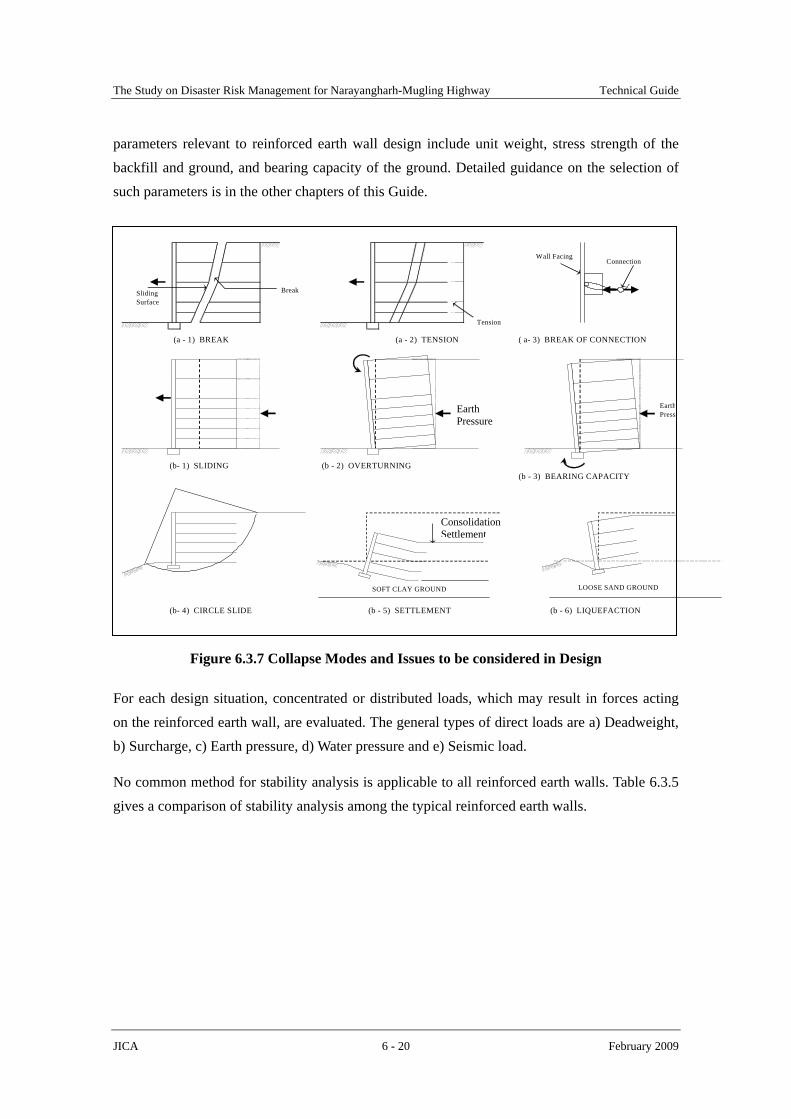
In principle, the design of reinforced earth walls includes (a) Internal stability analysis, (b) External stability analysis, and (c) Overall stability analysis, as graphically shown in Figure 6.3.7. For (b), the stability analyses are similar to that for retaining walls, including sliding, overturning and bearing capacity of the foundation.
Figure 6.3.8 gives the general design procedure for reinforced earth walls. Geotechnical
(c) Geotextile Reinforced Earth Wall
Wall Facing Material (concrete panel)
Steep belts Anchor plate & bar Geotextiles
The Study on Disaster Risk Management for Narayangharh-Mugling Highway Technical Guide
JICA 6 - 20 February 2009
parameters relevant to reinforced earth wall design include unit weight, stress strength of the backfill and ground, and bearing capacity of the ground. Detailed guidance on the selection of such parameters is in the other chapters of this Guide.
Figure 6.3.7 Collapse Modes and Issues to be considered in Design
For each design situation, concentrated or distributed loads, which may result in forces acting on the reinforced earth wall, are evaluated. The general types of direct loads are a) Deadweight, b) Surcharge, c) Earth pressure, d) Water pressure and e) Seismic load.
No common method for stability analysis is applicable to all reinforced earth walls. Table 6.3.5 gives a comparison of stability analysis among the typical reinforced earth walls.
(a - 1) BREAK (a - 2) TENSION ( a- 3) BREAK OF CONNECTION
(b- 1) SLIDING (b - 2) OVERTURNING(b - 3) BEARING CAPACITY
(b- 4) CIRCLE SLIDE (b - 5) SETTLEMENT (b - 6) LIQUEFACTION
SlidingSurface
Break
Tension
EarthPress
Settlement
SOFT CLAY GROUND LOOSE SAND GROUND
Wall FacingConnection
Earth Pressure
Consolidation Settlement

The Study on Disaster Risk Management for Narayangharh-Mugling Highway Technical Guide
JICA 6 - 21 February 2009
Table 6.3.5 Comparison of Stability Analysis for Typical Methods
Items to be evaluated Terre Armee Wall
Anchor Reinforced Earth Wall
Geotextile Reinforced Earth Wall
Sliding line for calculation 2 straight lines Circle line Active failure line
Break of reinforcement material ○ ○ ○ Tension of reinforcement material ○ ○ ○ In
tern
al
Internal sliding ─ ○ ─ Circle slide ○ ○ ○ Sliding of wall ─ ○ ○ Overturning of wall ─ ○ ─
Exte
rnal
Bearing capacity of ground for walls ─ ○ ○ Note: ○ = Must be evaluated, ─ = No need to be evaluated. Source: Modification from DESIGN AND CONSTRUCTION MANUAL FOR MULTISTAGE ANCHOR TYPE
REINFORCED EARTH WALL, Published by Public Works Research Institute, October 2002.
Figure 6.3.8 Schematic Drawing of Reinforced Earth Walls
START
NoIs the planned factor of safety met?
Yes
END
Additionalmeasures
2. Calculation of the required resistance of reinforcement materials: 1) Calculation of earth pressure acting to wall facing, 2) Determination of potential sliding surface
1. Determination of design conditions: 1) Shape of structure, 2) Parameters of backfill and ground, 3) Loads
3. Selection and arrangement of reinforcement materials: 1) Type and design tensile strength of reinforcement material, 2) Interval and length of reinforcement materials to be placed
4. Analysis of the internal stability of reinforcement materials: 1) Break, 2) Tension, 3) Break of connection
5. Analysis of the external stability of reinforced areas: 1) Sliding, 2) Overturning, 3) Bearing Capacity
6. Analysis of the overall stabiity: 1) Circle slide, 2) Settlement and liquefaction, if necessary
Is the stability ensured?
7. Calculation and design of detailed structures
Yes
No

The Study on Disaster Risk Management for Narayangharh-Mugling Highway Technical Guide
JICA 6 - 22 February 2009
The retaining effect of reinforced earth walls depends primarily upon the tensile resistance between the reinforcement materials and backfill materials. The effective tensile resistant force (R/Fs) is calculated by using the following equation.
s
E
s FLc
FR ×+=
)tan(2 φσ
Where,
R=Tensile resistance force of reinforced material in unit width (kN/m)
Fs=Factor of safety for tensile resistance
c=Cohesion between reinforcement material and backfill material (kN/m2)
φ=Frictional angle between reinforcement material and backfill material (degrees)
LE=Embedding length=length of reinforcement material below sliding surface (m)
Table 6.3.6 gives the effective tensile resistance forces of typical reinforcement materials in the case of backfill materials having a frictional angle of 30 degrees.
Table 6.3.6 Effective Tensile Resistance Force of Typical Reinforcement Materials Reinforcement
Materials Dimension of
Reinforcement MaterialsConditions of
Placement Effective Tensile
Resistance Force (kN/m) 1) 100% 1) σtan30o×LE Geogrids 1 to 3.7 m in width 2) 50% 2) σtan30o×LE 1) ⊿B=1.5m 1) (0.93+σtan1.6o) ×LE 2) ⊿B=1.0m 2) (1.39+σtan2.5o) ×LE 3) ⊿B=0.75m 3) (1.86+σtan3.3o) ×LE 4) ⊿B=0.50m 4) (2.79+σtan4.9o) ×LE 5) ⊿B=0.375m 5) (3.72+σtan6.6o) ×LE
Steel belts (strips) 60 mm
6) ⊿B=0.25m 6) (5.58+σtan9.7o) ×LE Anchor plates & bars
⊿B=0.75m, LE≧1.2m σtan28.3o, (Fs =3.0)
Notes: (1) The effective tensile resistant forces were calculated on the basis of backfill with a frictional angle of 30 degrees.
(2) ⊿B = Horizontal interval of reinforcement materials. Source: Modification from Bulletin of Civil Engineering Works 1998.11, Latest Technical Status of Reinforced Soil
Table 6.3.7 gives the applicability of backfill materials for different types of reinforced earth walls.

The Study on Disaster Risk Management for Narayangharh-Mugling Highway Technical Guide
JICA 6 - 23 February 2009
Table 6.3.7 Applicability of Backfill Materials Backfill Materials Methods Reinforcement
Materials Fine Fraction Coarse Fraction Geotextile Reinforced Earth Wall Geogrids Less than 50%
Terre Armee Wall Strips Less than 25% GM ≦ 300 mm Anchor Reinforced Earth Wall
Anchor plates & bars
WL ≦ 50% or fine fraction is more than 50% when WL ≧ 50% GM ≦ 300 mm
Note: GM = Maximum diameter grain size, WL = Liquid limit.
In order to maintain the reinforcement effectiveness of the reinforced earth walls, backfill drainage must be carefully considered and designed. Figure 6.3.9 gives an example of a road slip restored using a Terre Armee Wall.
Figure 6.3.9 Example of a Road Slip Restored Using a Terre Armee Wall
Collapse surface of road slip
Bedrock
Road
Ground line before road slip
Embackment Work
Terre Armee Wall
9.0
m

The Study on Disaster Risk Management for Narayangharh-Mugling Highway Technical Guide
JICA 6 - 24 February 2009
6.4 Construction of Retaining Walls
Retaining walls should be carefully constructed because these structures are designed to retain the extensive earth pressure and therefore the failure of these structures will result in the severe damage not only to the road facilities but also to the road users.
6.4.1 Foundation Work
The foundation works for retaining walls should be considered as follows:
a) The bearing ground should be excavated to a depth required for placing a footing if it is bedrock, the excavated foundation surface of bedrock should be cleaned, and then the spread footing should be placed.
b) If the bearing ground is earth or gravel, rubble stones should be laid over the excavated surface and rolled fully and uniformly, leveling concrete should be poured over the rubble stones, and then the spread foundation should be placed over it.
c) If the bearing ground is slanted, the portion at the valley side should be excavated in the form of steps and the rock should be replaced with concrete to the bedrock line to form a horizontal, uniform foundation. After this, the body of retaining walls or sabo dams should be directly constructed over the foundation.
d) If the bearing ground is soft and compressible, a pile foundation should generally be applied. In addition, if the soft ground (or stratum) is thin or if replacing material is easily available, the soft ground should be replaced with good quality soils so that the retaining walls may be built directly over the replaced material.
e) Timber piles, for example, 80 to 100 mm in diameter, 2.0 m to 3.0 m long, may be installed on gabion walls at longitudinal spacing of 3.0 to 4.0 meters to prevent the deformation of the gabion from the earth pressure of the back slope.
6.4.2 Backfill Work
Backfilling should be not allowed until the retaining structure become stable and strong enough to resist the earth pressure.
a) Only selected quality materials should be used to backfill the retaining wall.
b) Compaction is completely required.
c) Rain water should be completely prevented from flowing into the portion of backfilling.

The Study on Disaster Risk Management for Narayangharh-Mugling Highway Technical Guide
JICA 6 - 25 February 2009
d) Drainage facilities must be provided in order to drain the seepage water. Especially weep holes must always be provided with a rate of one weep hole per 2-4 m2 of retaining wall.
In addition, in principle, anti-proof sand treatment behind the walls should be placed between the walls and the back slope or backfilling to prevent the flow out of fine soil from the back slope, and hence preventing from disturbing the stability of soil mass behind the walls.

The Study on Disaster Risk Management for Narayangharh-Mugling Highway Technical Guide
JICA 7 - 1 February 2009
CHAPTER 7
ROCK FALL PREVENTION WORKS
7.1 General
Rock fall, a rapid movement of individual rock blocks or small-scale rock mass on a steep rock face, is one of the main road slope disaster along the N-M highway. As seen along the N-M highway, lots of steep, high and long rock faces are close to the highway, and therefore, because of its high speed can cause considerable damage to vehicles, death or injury to drivers and passengers, and economic loss due to road closures.
Some road sections along the N-M highway require countermeasures against rock fall. However, no any rockfall prevention works have been implemented yet. This is due partly to less or no experience with rock fall prevention in Nepal.
For this reason, this chapter introduces several rockfall prevention works, including rock fall prevention net and fence, and rock shed, which are considered to be most useful for minimizing hazards to the traveling public at present and in the future.
Moreover, reference is made to Chapter 6 of this Technical Guide for the design of retaining walls, which can be used as catch walls especially where there is space between the highway and the rock face.

The Study on Disaster Risk Management for Narayangharh-Mugling Highway Technical Guide
JICA 7 - 2 February 2009
7.2 Calculation of Impact Force of Falling Rocks
Countermeasures against rock fall shall be designed with the assumption that the external forces are to be safely borne by each countermeasure and by using these as design external forces.
7.2.1 Motion Mechanism of Rockfall
The motion of falling rocks on a steep slope is divided into three types, namely, sliding, rolling and bouncing, as illustrated in Figure 7.2.1. These motion patterns change into other forms, as shown in Figure 7.2.2.
In designing countermeasures for rock fall, the weight, speed, direction and position of the falling rocks is determined on the basis of the survey and/or history of rock fall in the specific area.
Motion pattern Sliding Rolling Bouncing
Diagram
Characteristics Slides down slopes Rolls down a slope Bounces in the air and moves downwards
Falling speed Slow Average Fast
Bounce height Zero Small Great
Figure 7.2.1 Illustration of Motion Mechanism of Falling Rocks
Figure 7.2.2 Motion Pattern of Falling Rocks
Source: Modification from MANUAL FOR COUNTERMEASURES AGAINST ROCK FALL, Published by Japan Road Association, June 2000.
7.2.2 Velocity of Falling Rocks
Among the three motion patterns, the velocity of falling rocks moving down a slope is highest
Bouncing
Linear motion
Parabolic motion
Free fall
Occ
urre
nce
of
Roc
k Fa
lls
Col
lisio
n
Sliding Rolling

The Study on Disaster Risk Management for Narayangharh-Mugling Highway Technical Guide
JICA 7 - 3 February 2009
during the bouncing motion. The velocity of a falling and bouncing rock block along a slope is less than that of the freely falling rock in the air from the same height.
Empirically, the following relationship is used to calculate the velocity of a falling and bouncing stone.
ghV 2×=α
θµα
tan1−=
Where, V= Velocity of a falling and bouncing stone (m/s)
gh2 = Velocity of a freely falling rock in the air (m/s)
α= Coefficient of velocity reduction
g= Gravity acceleration (m/s2)
H= Falling height (m)
µ= Equivalent coefficient of friction of the slope
θ= Gradient of the slope (degrees)
Table 7.2.1 gives the recommended coefficient of friction based on experiments for different kinds of slopes.
Table 7.2.1 Kinds of Slopes and Values of the Equivalent Coefficient of Friction
Class Characteristics of Rock Falls and Slopes Value of μ
Used for DesignRange ofμ
Obtained from Experiments
A 1) Hard rocks, round shapes, 2) Small concave and convex rocks, no standing
trees. 0.05 0.0 ~ 0.1
B 1) Soft rocks, square to round shapes, 2) Medium to large concave and convex rocks,
no standing trees. 0.15 0.11 ~ 0.20
C 1) Sediment, talus, round to square shapes, 2) Small to medium concave and convex rocks,
no standing trees. 0.25 0.21 ~ 0.30
D 1) Talus, talus with boulders, square shapes, 2) Medium to large concave and convex rocks,
with or without standing trees. 0.35 0.31 or more
Source: Modification from MANUAL FOR COUNTERMEASURES AGAINST ROCK FALL, Published by Japan Road Association,
June 2000, and DESIGN GUIDE -EARTHWORKS, Published by Japan Highway Public Corporation, May 1998.

The Study on Disaster Risk Management for Narayangharh-Mugling Highway Technical Guide
JICA 7 - 4 February 2009
7.2.3 Kinetic Energy of Falling Rocks
When designing countermeasures for rock falls, it is necessary to calculate the kinetic energy of the falling rocks by means of energy calculations.
Kinetic energy of falling rocks is expressed by the sum of the linear velocity energy and rolling energy, as follows:
rv EEE +=
HgmE ×××−×+= )tan
1()1(θ
µβ
Where,
E= Kinetic energy of falling rocks (t/s2)
Ev= Linear velocity energy of falling rocks (=1/2mV2)
Er= Rolling energy of falling rocks
m= Mass unit of falling rocks (t)
β= Rolling energy ratio (=Er/Ev) and 0.1)tan
1()1( ≤−×+θ
µβ
In the above equation, the value of β is generally in the range of 0.1 to 0.4, and 0.1 shall be used most frequently for design calculations.
From the results of experiments conducted, the height of the bounce of the falling rocks increases as the height of freefall becomes larger, but does not exceed 2 meters in most cases. Therefore, a bounce height of 2 meters is frequently used as the acting position of the design external force for countermeasure design.
7.2.4 Impact Force of Falling Rocks
Rock fall protection works shall be designed by converting the impact force of falling rock to a static force and by using the allowable stress method instead of the energy calculation method.
Since the impact force of falling rocks is considerably large, it is advantageous to use shock-absorbing materials to economically design these countermeasures, such as sand mats.
If the shock absorbing material is assumed to be an elastic body with a semi-infinite thickness and the specific gravity of the falling rock is assumed to be 2.6, then the maximum impact force Pmax of the falling rock can be expressed by the following equation:

The Study on Disaster Risk Management for Narayangharh-Mugling Highway Technical Guide
JICA 7 - 5 February 2009
53
52
32
max )(108.2 HgmP ××××= λ
Where,
Pmax= The maximum impact force (kN)
λ= Lame’s constant (kN/m2) (referring to Table 7.2.2)
H= Height of freefall of rocks (m)
Table 7.2.2 Lame’s Constant of Shock Absorbing Materials
Material conditions Constant (kN/m2) Remarks 1. Very soft 1,000 2. Soft 3,00 to 5,000 3. Hard 10,000
Note): 1 t/m2 = 10 kN/m2. Source: Modification from MANUAL FOR COUNTERMEASURES AGAINST ROCK FALL, Published by Japan
Road Association, June 2000

The Study on Disaster Risk Management for Narayangharh-Mugling Highway Technical Guide
JICA 7 - 6 February 2009
7.3 Selection of Countermeasures
7.3.1 Classification of Countermeasures
Countermeasures for rock falls are classified into rock fall prevention works and rock fall protection works. Rock fall prevention works involve the rock fall source, such as removal of the rocks and crib work, while rock fall protection works aim at protecting the relevant objects from the damage of rock fall. Table 7.3.1 includes the most common countermeasures divided into these two categories.
Table 7.3.1 Classification of Countermeasures for Rock Falls
CLASSIFICATION TYPE OF WORK Removal
1. EARTH WORK Earth work Re-Cutting
2. DRAINAGE WORK Surface drainage Drainage ditches Supporting Stone/Concrete supporting
3. FIXING WORK Anchoring work Anchor/ Rock bolt Pitching work Stone /Concrete block Shotcrete work Mortar/Concrete
Concrete block cribs (precast) Cast-in-place concrete cribs
4. SLOPE PROTECTION WORK Crib work
Shotcrete cribs Catch fill and ditches Catch walls (concrete and gabion) 5. CATACH WORK Catch work Catch fences/Net
6. ROCK SHED Rock shed Rock sheds
7.3.2 Selection of Countermeasures
Adequate and effective measures for preventing rock fall are selected in consideration of topographical and geological conditions, falling causes, vegetation, rock fall history, and effects of the countermeasure by predicting the size and height of the rock fall.
In selecting countermeasures, consideration should be given the following points:
a) If there is a danger of rock fall, in principle, the rock fall source should be removed. When these methods are difficult to be implemented, other methods should be adopted.
b) In selecting countermeasures, it is essential to consider not only the conditions of slope and rock fall, but also the road structure, traffic conditions and ground conditions.

The Study on Disaster Risk Management for Narayangharh-Mugling Highway Technical Guide
JICA 7 - 7 February 2009
c) It is necessary to combine various kinds of works together because the function of the various types of countermeasures for rock falls is limited, as shown in Figure 7.3.1.
Figure 7.3.1 Combinations of Countermeasures
d) Countermeasures for rock falls are designed by assuming the external forces to be safely borne by each work and by using this as design external forces.
For designing rock fall protection works, the following objectives must be considered:
a) Effectiveness in absorbing the energy of falling rocks,
b) Effectiveness in changing the direction of falling rocks to direct them to fall in areas where they will inflict no or minimal damage, and
c) Effectiveness in reducing the impact force and to halt the motion of the rocks.
In selecting the proper countermeasures, their effectiveness and capability to resist the energy of falling rocks are to be carefully considered. In general, the effectiveness of the protection works in absorbing the energy of falling rocks are in the following order from least to greatest: rock fall catch nets, rock fall catch fences, rock fall catch walls and rock sheds.
On the other hand, in selecting rock fall prevention works, care must be taken to ensure an appropriate combination of protection works. Effective combinations of countermeasures against rock falls are often determined by the function, durability, construction ease, construction cost and maintenance requirements of each type of countermeasure, as well as the conditions of the roads and slopes.
Table 7.3.2 summarizes the application of these countermeasures.
Original ground line
Catch ditch
Catch fill
a) Catch ditch + Catch fill
RoadRoad
Catch walll
Catch fence
b) Catch wall + Catch fence

The Study on Disaster Risk Management for Narayangharh-Mugling Highway Technical Guide
JICA 7 - 8 February 2009
Table 7.3.2 Application of Countermeasures for Rock Falls
Types of Work Durability Maintenance Construction Ease
Construction Cost
Degree of Safety
Removal ◎ ◎ △ ○ ◎ Re-cutting ○ ○ ○ ○ ○ Drainage ditches ○ ○ ○ ◎ ○ Stone pitching ◎ ◎ ○ ◎ ○ Block pitching ◎ ◎ ○ ◎ ○ Concrete pitching ◎ ◎ ○ ◎ ○ Mortar spraying ○ ○ ◎ ◎ ○ Concrete spraying ◎ ◎ ○ ◎ ○ Concrete block cribs ◎ ○ ○ ◎ ○ Cast-in-place concrete cribs ◎ ◎ ○ ○ ◎ Shotcrete cribs ◎ ○ ○ ◎ ○ Stone supporting △ △ ◎ ◎ △ Concrete supporting ◎ ◎ ◎ ◎ ◎ Rock bolt/ Ground Anchor ◎ ◎ △ △ ◎ Catch fill and ditches ◎ ○ ◎ ○ ○ Catch walls ◎ ○ ◎ ◎ ○ Catch fences ○ ○ ◎ ◎ ○ Catch nets ○ ○ ◎ ◎ ○ Rock sheds ◎ ◎ △ △ ◎
Note: ◎ = Very good or very easy, ○ = Good or easy, △ = Good or easy in some cases. Source: Modification from MANUAL FOR COUNTERMEASURES AGAINST ROCK FALL, Published by Japan
Road Association, June 2000
Their characteristics of each work are briefly described below:
(1) Earth Work
It is subdivided into removal and Recutting. Removal is one of the basic methods and should be adopted prior to execution of any slope protection work such as installation of anchoring and crib works. This work is frequently used when the fixing work is not applicable.
Recutting is applied for overhang slope or when the gradient of a slope is very steep.
(2) Drainage Work
For suspicious slopes of rock fall due to surface water, drainage work such as top slope ditch and berm ditch should be applied. However, where slopes are composed of hard rocks, this work may not be required because hard rocks may not be eroded and scoured due to surface water.
(3) Fixing Work

The Study on Disaster Risk Management for Narayangharh-Mugling Highway Technical Guide
JICA 7 - 9 February 2009
This work is applied for slopes where big and support-less rock blocks exist and the removal of those blocks are considered to be costly and difficult.
(4) Slope Protection Work
For slopes composed of materials that are easily eroded, scoured and weathered, slope protection works are more recommendable.
(5) Catch Work
Rock fall generally occur from slopes composed of hard rocks with developed cracks and joints, even though there is no erosion, scouring and weathering. For these slopes, fixing work may be adopted, especially if the gradient of slopes is very steep and re-cutting is not practical.
This work is also used when proper countermeasures can not be applied due to limitation within the area of the slope
(6) Rock Shed
This work is adopted for slope where rock fall are very large in size and other countermeasures are considered to be impractical and costly. This work is usually used for large-scale rock fall.

The Study on Disaster Risk Management for Narayangharh-Mugling Highway Technical Guide
JICA 7 - 10 February 2009
7.4 Design of Main Countermeasures
7.4.1 Rock Fall Catch Nets
Rock fall catch nets (or rock fall prevention net) consist of nets and wire rope and include two major types: cover type and pocket type. The cover type rock fall catch net is able to restrain loose rocks by means of the net tension and friction between the rocks and the ground. The pocket type rock fall catch net is installed with the upper end of the net separate from the surface of the slope. Falling rocks from the upper slope are caught in the gap between the net and slope.
(1) Purpose
Rock fall catch nets are used to cover slopes that have a potential for rock falls in order to protect road traffic from damage.
(2) Design considerations
Figure 7.4.1 shows the design procedure. Figure 7.4.2 gives an example of pocket type rock fall catch nets. When designing the pocket type rock fall catch net, the assumed point of collision of the falling rocks is at the center of the two posts and at the center between the top and second horizontal ropes.
Catch net is designed with the following considerations:
a) Energy of the falling rock
b) Energy absorbable by the net in such a manner that it will be able to withstand the energy of the falling rocks
c) Strength and stability of anchor on the assumption that the breaking of the rope will act to the anchor.

The Study on Disaster Risk Management for Narayangharh-Mugling Highway Technical Guide
JICA 7 - 11 February 2009
Figure 7.4.1 Design of Catch Nets Source: Modification from MANUAL FOR COUNTERMEASURES AGAINST ROCK FALL,
Published by Japan Road Association, June 2000
Figure 7.4.2 Example of Pocket Type Rock Fall Catch Net
Wire/Net
Anchor
(3.0-5.0m ) Pillar
Wire
(>10.0m )
5.0m
5.0m
3.0m 3.0m 3.0m
1.5m
Net
2.0m
2.0m
2.0m2.0m
Clip wire
Wire
Anchor
ROAD
a) Catch wire net b) Anchor wire net
START
No
Determine the load of falling rocks andthe deadweight of net to be used for the design
Is absorbabale energybigger than energy of
falling rocks?
Yes
Determine the diameter of vertical rope capable of resisting the deadweight and load of falling rocks expected to appear throughout the whole length of slope
Determine the diameter and spacing of horizontal rope capable of resisting the deadweight of the rope and weight of falling stones expected to appear in the 3 lower spans in the direction of length of slope
Determine the kind of wire net
Review the strength and stability of anchor
END
START
Calculate the energy of falling stones
Calculate the absorbable energy : 1) Energy absorbed by net 2) Energy absorbed by rope 3) Energy absorbed by post 4) Difference in energy before and after the collision of falling rocks
Review the strength and stability of anchor
END
a) Cover type rock fall catch net b) Pocket type rock fall catch net
The Study on Disaster Risk Management for Narayangharh-Mugling Highway Technical Guide
JICA 7 - 12 February 2009
7.4.2 Rock Fall Catch Fences
Rock fall catch fences consist of fences made of net and wire rope attached to steel pipes or H-section posts. This type of fence has the capacity to absorb the energy of falling rocks.
(1) Purpose
Rock fall catch fences are intended to protect road traffic from rock fall damage, but differ from rock fall catch nets in that they are installed near the road.
(2) Design considerations
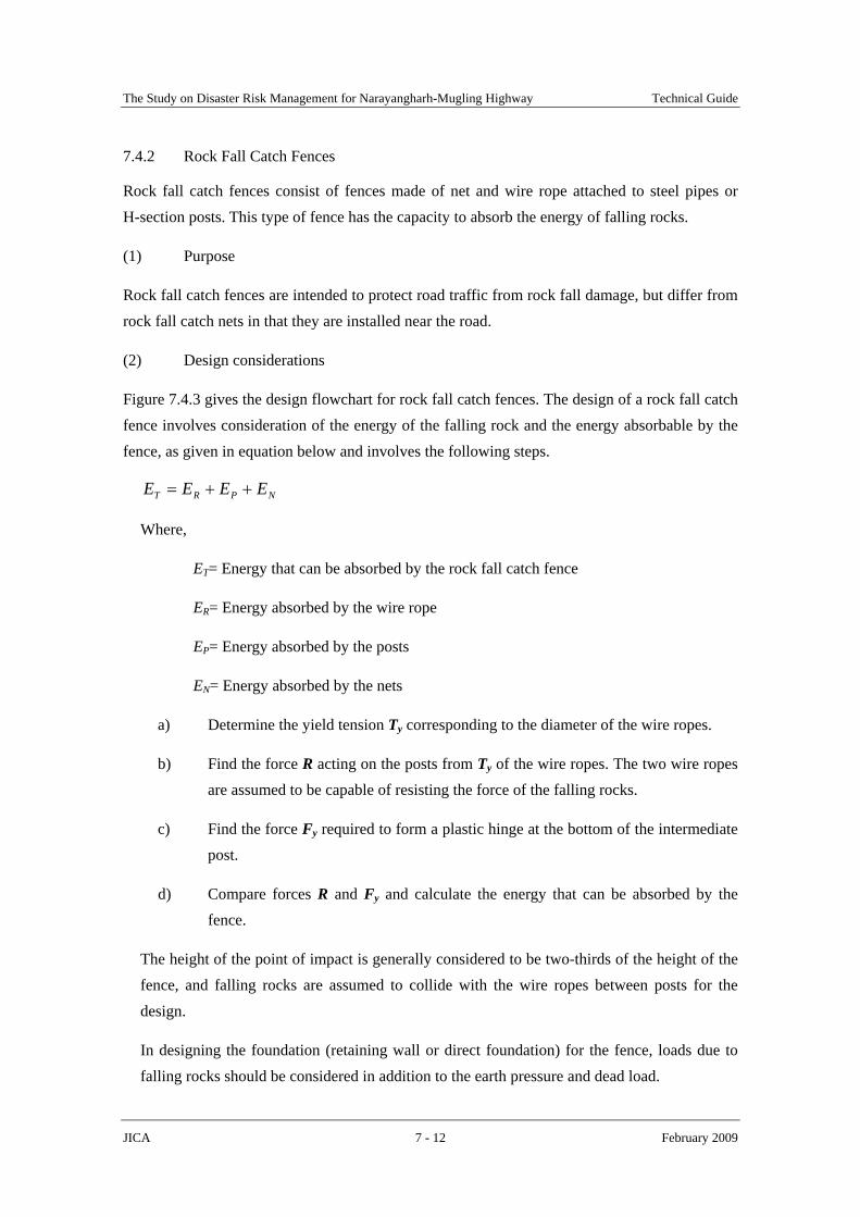
Figure 7.4.3 gives the design flowchart for rock fall catch fences. The design of a rock fall catch fence involves consideration of the energy of the falling rock and the energy absorbable by the fence, as given in equation below and involves the following steps.
NPRT EEEE ++=
Where,
ET= Energy that can be absorbed by the rock fall catch fence
ER= Energy absorbed by the wire rope
EP= Energy absorbed by the posts
EN= Energy absorbed by the nets
a) Determine the yield tension Ty corresponding to the diameter of the wire ropes.
b) Find the force R acting on the posts from Ty of the wire ropes. The two wire ropes are assumed to be capable of resisting the force of the falling rocks.
c) Find the force Fy required to form a plastic hinge at the bottom of the intermediate post.
d) Compare forces R and Fy and calculate the energy that can be absorbed by the fence.
The height of the point of impact is generally considered to be two-thirds of the height of the fence, and falling rocks are assumed to collide with the wire ropes between posts for the design.
In designing the foundation (retaining wall or direct foundation) for the fence, loads due to falling rocks should be considered in addition to the earth pressure and dead load.

The Study on Disaster Risk Management for Narayangharh-Mugling Highway Technical Guide
JICA 7 - 13 February 2009
Figure 7.4.3 Design Flowchart for Rock Fall Catch Fences Source: Modification from MANUAL FOR COUNTERMEASURES AGAINST ROCK FALL, Published by Japan
Road Association, June 2000
Ei= Energy of falling rocks for design
m= Unit mass of falling rocks
H= Free fall height
θ= Gradient of a slope (degrees)
µ= Equivalent coefficient of friction
of the slope
β- Rotational energy ratio
h1- Bounce height of falling rocks
l: Width of flat area
ET: Absorbable energy by fence
g: Gravity acceleration
case(2)(i) case(1)
case(2)(ii)
(h1secθ - h1)cotθ
h 1
h
l
l
θ
h1
Determine the falling rocks to be used for design: 1) Weight of falling rocks (W) 2) Falling height of fall rocks (H)
Calculate the energy of falling rocks (Er): 1) Ei=(1+β)(1-µ/tanθ)m·g·H
Determine the section of post, and number and number of ropesso as to satisfy the following condition: ET > Ei
END
START
Determine the height of rock fall catch fence: 1) With flat area (Case 1) h>h1secθ 2) With small flat area of l in width (Case 2) i) When 0<l <(h1secθ-h1)cotθ, h>(h1secθ-l tanθ) ii) When l>(h1secθ-h1)cotθ, h>h1
Conditions of falling rocks Conditions of slopes
Determine the shape and size of the foundation, so as to prevent the foundation from being broken even after plastic deformation of the posts.
When ET ≦ Ei , consider seperately

The Study on Disaster Risk Management for Narayangharh-Mugling Highway Technical Guide
JICA 7 - 14 February 2009
Table 7.4.1 Standard Specifications for Rock Fall Catch Fences
Post Height of
Fence (m)
Size and Type Sectional Coefficient (cm3)
Interval (m)
Wire Rope Wire Net
1.5 2.0 2.5 3.0 3.5
H-200×100×5.5×8 181
4.0 4.5 5.0 5.5 6.0
H-200×100×8×12 472
3.0
3×7G/0, φ18 Sectional area:
A = 129 mm2 Elastic coefficient
Ew = 105 N/mm2 Fracture strength
Tb = 157 kN Yield strength
Ty = 118 kN
diamond shape φ 3.2 × 50×50
Source: Modification from MANUAL FOR COUNTERMEASURES AGAINST ROCK FALL, Published by Japan Road Association, June 2000
7.4.3 Rock Sheds
Rock sheds are reinforced concrete or steel structures covering a road and can be subdivided into four types from the structural viewpoint; portal (gate) type, retaining wall type, arch type and pocket type (Figure 7.4.4).
This method is very costly and would only be planned and designed in areas of extreme rock fall hazard.
Figure 7.4.4 Types of Rock Sheds
ROAD ROAD
Jointed Rock
b) Retaining Wall Typea) Portal Type
Deposited mass
Absorption materials
Jointed Rock

The Study on Disaster Risk Management for Narayangharh-Mugling Highway Technical Guide
JICA 7 - 15 February 2009
(1) Purpose
This method is applied to reduce road disasters due to rock fall or rock mass failure by absorbing the impact force of a falling rock mass or changing the direction of the movement of rock mass failure and rock falls.
(2) Design considerations
The most important design consideration should be the calculation of the impact force of the falling rock mass. Rock sheds are designed after converting the impact force into a static force according to the allowable stresses design method. For the purpose of simplifying the calculations, the area on which the impact load is calculated is assumed to be rectangular rather than circular.
The design procedure generally involves the following steps shown in Figure 7.4.5. The kinds and combination of loads to be considered in the design of the rock shed are shown in Table 7.4.2.
Figure 7.4.5 Design Procedure for Rock Sheds
END
ST ART
Ste p 1: De s te rmine Conditions of rock falls and s lope s 1) Conditions of rock falls a) Scale of rock fall, b) falling height, c) Size of falling rocks , d) Others 2) Conditions of slopes a) Geology, b) Gradient of s lope, c) Vegetation of s lope, d) Height of s lope, e) Others
Ste p 2: Calculate loads to be cons ide re d in the de s ign 1) Kinds of loads a) Dead load, b) Earth and water pres s ures , c) W eight of depos ited materials , d) Impact load of falling rocks , e) Earthquake s kock 2) Combination of loads a) In normal cas e, b) In s eis mic case, c) A t occurrence of rock falls , d) Others (when being impacted by car) if necess ary
Ste p 3: Calculate and de s ign the s trucute s 1) Study on alternative structures a) Upper s tructures , b) Lower s tructures at mountain s ide, c) Lower s tructure at valley s ide 2) Structural calculations a) Check the s tability of foundation, b) Check the allowable s trength of each kind of materials to be us ed

The Study on Disaster Risk Management for Narayangharh-Mugling Highway Technical Guide
JICA 7 - 16 February 2009
Furthermore, in the conventional design method, the dispersion of loads on the roof slab of the rock shed is simplified, as shown in Figure 7.4.6.
Table 7.4.2 Combinations of Loads for Design of Rock Sheds
Dea
d lo
ad
Earth
pre
ssur
e
Wat
er p
ress
ure
Wei
ght o
f D
epos
ited
mat
eria
l
Roc
k fa
ll
Earth
quak
e
Impa
ct b
y ca
r
Coefficient of increase in allowable unit stress
1) In normal case ○ ○ △ △ 1.00
2) At occurrence of rock fall ○ ○ △ ○ 1.50 3) In seismic case ○ ○ △ △ ○ 1.50 4) At impact by car ○ ○ △ △ ○ 1.50
Note: 1) Three cases, namely normal, seismic and rock fall cases must be combined in the design. 2) ○ = Loads expected must be considered in any case, △ = Loads should be considered
according to site conditions. Source: Modification from MANUAL FOR COUNTERMEASURES AGAINST ROCK FALL, Published by
Japan Road Association, June 2000
Figure 7.4.6 Loading Method for Impact Load
Source: Modification from MANUAL FOR COUNTERMEASURES AGAINST ROCK FALL, Published by Japan Road Association, June 2000
P
hImpact Absorbing
Materials
Roof Slab
45 o 45 o
A = π h 2 /4√π×h/2
Falling Rock
√π×h/2

The Study on Disaster Risk Management for Narayangharh-Mugling Highway Technical Guide
JICA 8 - 1 February 2009
CHAPTER 8
MAINTENANCE AND REPAIR
8.1 General
Most of road slope structures, such as retaining walls, drainage ditches, and vegetation, will gradually deteriorate and weaken naturally and/or artificially after their construction. Because of progressive deterioration and deformation, these structures (or works) may lose their originally expected functions and result in road slope disasters in the worst cases.
On the other hand, the road slopes, including cut slopes and natural slopes, are mostly the main sites of sediment disasters such as landslides, slope failures and rock falls because road excavation disturbs the initial stability of the slopes and facilitates erosion, scouring and weathering of the slopes.
Therefore, fulfillment of regular maintenance activities is indispensable to early recognition of abnormal phenomena; landslide, slope failure, structural deformation or crack, which could avert risk by a hazard and also minimize consecutive loss.
The purpose of the maintenance of road slopes is to identify and determine the potential road disaster sites that have the possibility to cause road disasters and associated traffic problems, to take prompt and corrective action to return the road slopes to usable and stable conditions, and to minimize hazards to the traveling public.
Further, as mentioned above, the road facility involves natural slopes and slopes with structures. The maintenance of road slope will discuss on the following three categories in this chapter:
a) Maintenance of natural slopes
b) Maintenance of slopes with structures, and
c) Maintenance of streams cross the road, including sabo facilities
Basically, the first maintenance work is to inspect the abnormal situations of natural slopes. If there are any signs of deformation and movement, and a road disaster are judged to be likely to occur, monitoring and related emergency measures are required.
The second maintenance work, on the other hand, may be to a) inspect the present conditions of structures, b) maintain the functions of structures, and c) implement structural measures in case

The Study on Disaster Risk Management for Narayangharh-Mugling Highway Technical Guide
JICA 8 - 2 February 2009
of emergency.
The third maintenance work, similar to the second work, deals with streams and related sabo facilities.
This chapter, therefore, focuses on the following:
a) Inspection on natural and cut slopes, road structure, road-related streams and sabo facilities
b) Routine maintenance and repair on the above-mentioned structures and facilities
c) Emergency measures for road disasters

The Study on Disaster Risk Management for Narayangharh-Mugling Highway Technical Guide
JICA 8 - 3 February 2009
8.2 Inspection
Regular inspection and monitoring herein involve mainly slopes and the structures fulfilled by the preventive works, particularly focusing on those abnormal situations and signs of deformation occurring in the road slopes and structures.
Benefit of regular inspection program of road slopes are as follows:
a) To aid in identifying potential landslide area and damaged structures to need repair
b) To trace the progression of a potential landslide from year to year
c) To provide vital information for establishing a priority program for allocating monies and repair
d) To provide vital and historical data for technical staff for review
e) To aid in establishing future budget plan
f) To aid in establishing an appropriate course of action
8.2.1 Frequency and Scope of Inspection
As we know, heavy rainfall has been regarded as the most important factor inducing road slope disasters in this project area. Road slope disasters have occurred almost during and immediately after heavy rainfall.
It is thus recommended that, as a minimum, inspections most be carried out twice a year before and after rainfall in consideration of the occurrence frequency of road disasters and the deterioration degree of the existing structures. It may be adjusted depending on slope conditions, ongoing status of the ground and structure deformation, earthquake and meteorological change. It is recommended, for instance, an additional inspection in case of heavy rain of 200 mm/day or after earthquake.
In addition, a technical staff and/or a geological engineer should do regular inspection if possible.
The inspection is at present proposed to be carried out in the following locations and elsewhere any sign of abnormal condition is recognized.
a) 10 locations selected for the Feasibility Study in the Study
b) All locations with preventive structures including sabo facilities along the N-M highway

The Study on Disaster Risk Management for Narayangharh-Mugling Highway Technical Guide
JICA 8 - 4 February 2009
c) Sta. 27km + 50
d) Sta. 26km + 700
Sta. 27km + 50 and Sta. 26km + 700 are two small-scale landslides cross the highway, which were identified during the Study. Their details are described in another Section of this chapter.
Later, as time and budget permit, the inspection could be expanded to include:
a) All cut slopes without vegetation cover
b) All fill slopes on the valley sides
c) All know landslides or suspected areas that may be prone to sliding.
In addition, a technical staff and/or a geological engineer should do regular inspection if possible.
8.2.2 Recording of Inspection
Inspection shall be made basically by visual observation to the sites; natural and artificial slopes, including bio-engineering work (vegetation), stone masonry wall, gabion wall, drainage ditch, horizontal drain hole, gabion sabo dam, natural slope, cut slope and road surface. The results of inspection shall be recorded and filed as database which is shown in Table 8.2.1 and Appendix 8-1 to 8-4.
Table 8.2.1 Members of the Steering Committee Sheet No. Name Purpose Description/data
Sheet 1. General Information
Selection and identification of sites to be surveyed
Location of site (km post, right/left of road, expected hazard type) - Photographs of site (slope/stream) situation - Description of general condition
Sheet 2. Evaluation of Existing Countermeasure
Detail observation of existing countermeasures
-Sketch of countermeasures - Evaluation of effectiveness of countermeasures - Priority ranking for rehabilitation
Sheet 3 Rehabilitation Plan Rehabilitation
- Plane layout of rehabilitation methods - Section layout of rehabilitation methods - Cost estimation [Rs]
Sheet 5 Inspection result
Compilation of inspection result
Compilation of inspection result for utilizing planning of rehabilitation
Rehabilitation plan can be made utilizing above mentioned inspection result.
During the inspection, careful attention should be paid on deformation, settlement and presence of cracks on slopes and structures, together with small collapses and springs, particularly focusing on those abnormal situations and signs of deformation occurring in the ground and structures.

The Study on Disaster Risk Management for Narayangharh-Mugling Highway Technical Guide
JICA 8 - 5 February 2009
The points to inspection and records are listed, in terms of every works and slopes, as follows.
(1) Vegetation work (seed work)
a) Partial erosion due to surface water or shallow collapse
b) Poor growth corresponding to the local geological conditions (clayey soil, sandy soil, bedrock, etc.)
(2) Wicker work
a) Conditions of slipped-down due to weight of deposited sediment and of floating due to erosion
b) Slipped-down due to inflow of rainwater or rot of stakes or wicker work
c) Intervals of stakes or some stakes likely be taken away
(3) Drainage ditch
a) Blockage by collapsed soils or others
b) Inclination, deformation, differential settlement due to landslide movement
c) Swamp around the structures due to leakage of water from these structures
d) Gap between the structures and the ground, due to surface water erosion and landslide movement
e) Concave at both sides of ditch
f) Crack and joints due to landslide movement
(4) Culvert box
a) Deformation and cracks around outlet and inlet
b) Conditions of gap between culvert and its surrounding
c) Deposition of sediment inside culvert
d) Connection with drainage ditch
(5) Horizontal drain hole
a) Spring around outlet
b) Collapse of outlet
c) Amount of collected water from each hole before and after rainfall

The Study on Disaster Risk Management for Narayangharh-Mugling Highway Technical Guide
JICA 8 - 6 February 2009
(6) Gabion wall
a) Looseness or deformation of materials filled inside wire mesh
b) Outflow of sediment behind gabion
c) Presence of wire cylinder rust
d) Presence of scour of foundation
e) Presence of subsidence of foundation
(7) Stone (or block) masonry wall
a) Cracks, settlement (size, distribution)
b) Disposal and conditions of spring water or seepage water
c) Presence of scour of foundation
(8) Rock fall prevent net
a) Cut nets and anchors
b) Deposition of fallen rocks or sediments
c) Loose anchor
(9) Rock fall prevention fence
a) Broken or bent posts of fences, conditions of rot
b) Deposition of fallen rocks or sediment
c) Weathering and failures of foundation
(10) Crib work
a) Looseness or sinking of material filled inside cribs
b) Cracking or deformation in cribs
c) Conditions of drainage
d) Outflow of sediment behind cribs
e) Presence of scour of foundation
(11) Anchor with retaining wall
a) Gap between the road surface and the settled embankment area
b) Ongoing conditions of wall inclination toward the river side

The Study on Disaster Risk Management for Narayangharh-Mugling Highway Technical Guide
JICA 8 - 7 February 2009
c) Deformation of anchor head
d) Conditions of rust of head device, pressure bearing plate and anchor bar
e) Presence and expansion of shallow collapses on the valley slopes
(12) Road surface
a) Cracks, gaps, settlement
b) Scour of surface
(13) Cut slope
a) Toe collapse, small collapse (depth and area)
b) Scour of surface water
c) Spring water and conditions of drainage
d) Poor cover of vegetation work
(14) Natural slope (landslide area)
a) Head scarp, stepped landforms
b) Cracks, subsidence, upheaval, depressions (length, depth)
c) Toe collapse, small collapse (width, depth)
d) Distribution and locations of spring water, swamp, etc.
(15) Stream
a) Distribution of new collapses on valley slopes
b) Depth and gradient of sediments on streambed
c) Amount of unstable sediments on streambed
(16) Gabion sabo dam
a) Looseness or deformation of materials filled inside wire mesh
b) Damage of crest parts
c) Presence of wire cylinder rust
d) Presence of scour and subsidence of foundation
e) Deposition of unstable sediment behind dam

The Study on Disaster Risk Management for Narayangharh-Mugling Highway Technical Guide
JICA 8 - 8 February 2009
8.3 Routine Maintenance and Repair
After inspection and monitoring, if some structures are partially weakened and locally damaged, or signs of a landslide movement are observed, maintenance and/or repair should be immediately made to these facilities and areas.
Routine maintenance and repair (RMR) activities are mainly, with simple, fast, cost-effective methods, as follows:
a) To repair the deteriorated structures
b) To recover the original functions of aged structures
c) To improve stability of a suspected landslide
Some practical maintenance and repair methods in response to different structures and road disasters are suggested below:
8.3.1 Bio-engineering work
Vegetation becomes only after the growth of the plants, and their effects can be continued for many years and only if they are properly maintained.
Maintenance and repair methods relating to vegetation are as follow:
a) To add fertilizer or re-vegetate with net for poor growth
b) To re-vegetate with wicker for broken covers, collapsed area due to erosion or slope failure
c) To place gabion or sandbag on the toe part of vegetated slopes to minimize the runoff erosion
8.3.2 Drainage work
(1) Drainage ditch and culvert box
Because water is the main cause of landslide and slope failure, the extra precaution should be taken for the drainage facilities. For drainage ditch, the following maintenance and repair should be done to keep its function:
a) To removal rock blocks and sediment inside ditch and culvert
b) To maintain interception ditch and culvert

The Study on Disaster Risk Management for Narayangharh-Mugling Highway Technical Guide
JICA 8 - 9 February 2009
c) To repair cracks, gap and joints in ditch and culvert with mortar
d) To fill gap and cracks between ditch/culvert and the ground with clay
(2) Horizontal drain holes
a) To repair the outlet with mortar, or with gabion work
b) To clean the drain hole by using pressured water with hose
c) To extend the drain pipe with PVC pipe. If the drainage pipe is terminated too short, this may allow water to discharge onto the slope again.
8.3.3 Retaining wall work
(1) Gabion wall
a) To install wooden pile (φ100 to 150, L=2 to 3.0 meters) on the valley side of gabion work, when subject to deformation
b) To fully fill the gap or subsidence between the wall and the ground to minimize the flowing of surface water into the ground behind the wall
c) To install stone masonry to reinforce its foundation when subject to foundation scouring. Also to direct surface water away from the damaged area by installing stone pitching ditch or similar structures
d) To repair the loosened or cut wire boxes with wire
(2) Stone masonry wall
a) To repair the damaged or broken wall with stones and mortar. Also to install weep holes
(PVC, φ40-50, L= L=2 to 3.0 meters) when the damage is considered to be due to spring erosion
b) To fully fill the gap or subsidence between the wall and the ground to minimize the flowing of surface water into the ground behind the wall
c) To fill cracks on wall with mortal
8.3.4 Sabo dam work
(1) Repair for gabion sabo dam
a) To place plain concrete of about 3 to 5 cm think on the crest part of a gabion sabo dam to prevent damage of wire mesh box from massive debris flow sediments

The Study on Disaster Risk Management for Narayangharh-Mugling Highway Technical Guide
JICA 8 - 10 February 2009
b) To install a apron of gabion mat, about 20 to 50 cm in thickness to prevent its foundation from scouring, when the scouring of foundation is considered to be severe
c) To install wooden pile (φ100 to 150, L=2 to 3.0 meters) on the valley side of gabion work, if possible, when subject to deformation or inclination
(2) Removal of deposit behind sabo dam
The main maintenance activity relating to sabo dam, including gabion and concrete sabo dams, is to remove the sediments deposited behind the dam in order to maintain their functions.
A number of sabo dams have been constructed along the mountain streams, especially on the mountain side of the road. These sabo dams were constructed mainly to catch the overall or partial deposits due to debris flow, and hence to prevent the road from hit of debris flow. In general, the functional recovery of an existing sabo dam by removing deposits is thus one of the most important and cost-effective methods. Figure 8.3.1 conceptually shows the functional recovery of existing sabo dams.
Figure 8.3.1 Conceptual Illustration of Functional Recovery for Sabo Dam
The sabo dams to be required for removal of deposit are recommended to be those sabo dams within about 100 m far from the road, in consideration of the easy access and a larger capacity of deposit catch after removal. on the other hand, sabo dams in the upstream are suggested to be excluded because they also have the same function as embankment to protect the toe failure of valley slope in addition of deposition of sediment.
Refer to the Drift Final Main Report prepared in this Study to know the sabo dams which are required for removal of deposits.
It is suggested that the removal of deposits be preferably completed before the rainy season. In addition, for the time being the removal of deposits should be conducted by manpower with some simple equipment, such as trolley, wooden channel, plastic hose etc. The wooden channel functions as flume to flow the deposits and is tentatively called Debris Flow Flume (DFF). The
Original streambed lineSabo dam
A: Removal of unstable depositsB: Removal of deposits to increase capacity
A
B

The Study on Disaster Risk Management for Narayangharh-Mugling Highway Technical Guide
JICA 8 - 11 February 2009
Debris Flow Flume should be reinforced with thin steel sheet inside to facilitate the flow of deposits. Figure 8.3.2 gives the schematic diagram for removal of deposit using DFF and the structural detail of the flume will be considered in the next stage.
Figure 8.3.2 Conceptual Illustration of Removal of Deposit with DFF
Further, it is suggested that, removal of deposits be implemented in the future by using a monorail car, as shown in Figure 8.3.3, because main of the following advantages:.
Figure 8.3.3 Examples of Simple Monorail Car Used on Steep Slopes
a) A monorail car easily runs on a narrow valley and steep slope with a speed of about 30 m/min to 40 m/min,
b) Installation of monorail is simple and easy,
c) Maintenance cost is very lower,
Debris Flow Flume (DFF)
Sabo dam
ROAD

The Study on Disaster Risk Management for Narayangharh-Mugling Highway Technical Guide
JICA 8 - 12 February 2009
d) Maximum slope for monorail car is 45 degrees,
e) Load weight is about 200 kg or more.
8.3.5 Landslide and failure
(1) Small landslide or slope failure
When a small landslide or slope failure has occurred, maintenance and repair should be done to prevent the landslide from becoming worse, or to slow or stop slide movement. These are as follows:
a) To place gabion or sandbag on the toe of failed slopes
b) To fill open cracks on its head portion and on both sides with clay
c) To direct the surface water away from the landslide area using pipe or stone pitching ditch
d) To cover the cracked port of the slope in order to prevent the infiltration of rainwater and to prevent progressive failure
e) To insert some PVC pipe if abundant spring is present
f) To flatten the upper portion of landslide area
g) To protect collapse scar with vegetation, if necessary, after becoming inactive
h) To reseed or re-vegetate the collapsed slopes immediately after re-cutting or repair
(2) Road shoulder slip
A road shoulder slip may be due to undercutting or erosion by overflow from hill slope. In the worst case, the right of way would be completely lost.
a) To direct runoff away from the slipped area
b) To seal cracks, gaps, subsidence on road surface with mortal or clay
c) To place gabion wall on the valley side to prevent road shoulder from erosion of runoff or undercutting

The Study on Disaster Risk Management for Narayangharh-Mugling Highway Technical Guide
JICA 8 - 13 February 2009
8.4 Emergency Measures
If any sign of large landslide or failure is found or any imminent event is identified, emergency measures should be immediately performed together with reevaluation of slope stability and study of preventive measures.
Emergency Maintenance is defined by DOR as "Maintenance needed to deal with emergencies and problems calling for immediate action when a road is threatened or closed."
In this Technical Guide, emergency measures as temporary works are, when an emergency event is identified or found, those works which can be implemented simply and fast in order to avoid large slope failure and subsequent damage before the required permanent works are commenced.
The following introduces several emergency works for road slope disasters. These emergency measures can generally be applied in combination.
8.4.1 Drainage
Surface and subsurface drainage is always one of the main emergency measures. Because many open cracks are always associated landslide movement (Figure 8.4.1a), top slope ditch by open-cut with plastic sheet or by rock pitching are more desirable to cut off flowing into from surrounding slopes.
If the landslide is moving, horizontal drain holes (PVC pipe) should be performed. It is notes that several drain holes (lateral boring) should be drilled across the open cracks approximately 10 to 20 m at 5 to 10 m intervals in the direction of cracks as shown in Figure 8.4.1.
River
Road
5 ~ 10 m Crack
LandslideBlock
Retaining Structure(Gabion Mat)
LateralBoring
C/L
10 ~ 20 m
SlidingSurface
LateralBoring
Road
River
GroundwaterLevel
a) Plan Image b) Longitudinal Image
Figure 8.4.1 Drainage Works as an Emergency Measure

The Study on Disaster Risk Management for Narayangharh-Mugling Highway Technical Guide
JICA 8 - 14 February 2009
8.4.2 Cutting Work for a Landslide
It is an effective measure in many cases to perform horizontal cutting of the soil mass by several meters at the head of a landslide as shown in Figure 8.4.2. However, this removal should not be performed if the upper slope of the cutting may become unstable, or if it is located at the tail of a secondary landslide area behind the proposed cut that may be predicted to slip
If the toe of the landslide is likely to collapse or if a failure is likely to enlarge, earth retaining works should be installed with cylinders or mat gabions at the toe.
C/L
Sliding Surface
OriginalSlope Line
Earth Removal
Road
Figure 8.4.2 Cutting Work as an Emergency Measure
8.4.3 Flatten Slope for Hill slope
If any signs of slope failures or open cracks are found on the upper slope or a slope failure has occurred, the scale and range of the failure or potential failure should be examined at first.
In case the slope failure has occurred only locally and there is no immediate danger of occurrence of other large-scale failures, then it is the simplest to take emergency measures by using wicker works. Besides the said situation, if the scale of the failure is large, it becomes necessary to secure the long-term stability by re-shaping the slope and providing a gentler gradient as shown in Figure 8.4.3.
8.4.4 Gabion Mat or Wall for Hill slope
If the slope failure is only local or partial on the lower portion of hill slopes, the failure surface should be protected by piling sand bags as an emergency work. If spring water is found flowing out from the failed portion, gabion mats should be recommendable and the appropriate surface water treatment also should be provided, as illustrated in Figure 8.4.4

The Study on Disaster Risk Management for Narayangharh-Mugling Highway Technical Guide
JICA 8 - 15 February 2009
Failure
Cracks
CollapseSoil
C/L
Surface Line forPermanent Restration
Step-1 : Removal of Collapse Soil & Covering with Vinyl Sheet
Surface Line forTemporary Stabilization
Step-2 : Temporary Cutting Slope to Stabilize on Failure Portion
Step-3 : Permanent Restoration Works
Covering withVinyl Sheet
FailureSurface
Figure 8.4.3 Example of Emergency Measures and Restoration after Cracks and Failure on the Upper Slope
CollapseSoil
C/L
Failure
Sand Bag
Emergency Countermeasure
a) Protection by Sand Bag
Stopping PileFixing Pile
Gabion Mat
b) Protection by Gabion Mat (Measure against Spring Water)
Spring Water
Figure 8.4.4 Example of Urgent Measure by Sand Bags or Gabion Mats
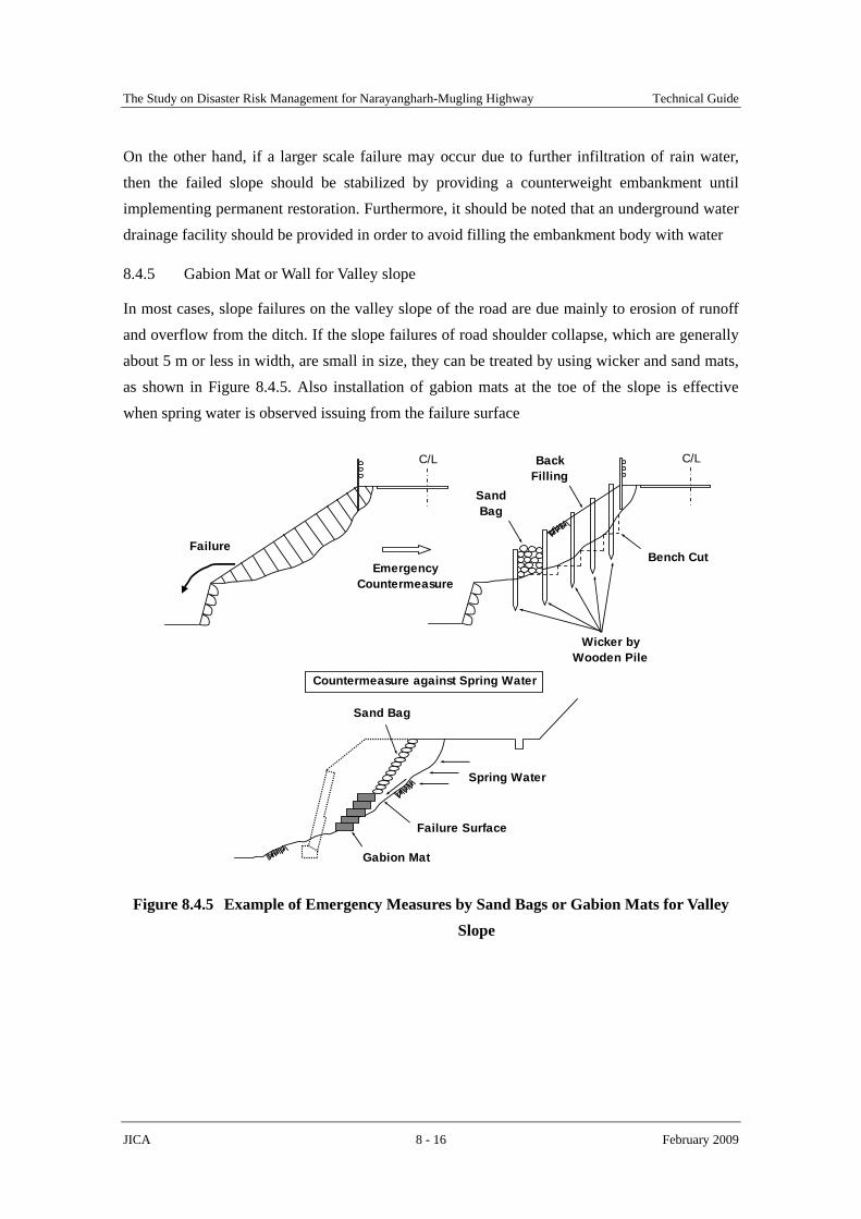
The Study on Disaster Risk Management for Narayangharh-Mugling Highway Technical Guide
JICA 8 - 16 February 2009
On the other hand, if a larger scale failure may occur due to further infiltration of rain water, then the failed slope should be stabilized by providing a counterweight embankment until implementing permanent restoration. Furthermore, it should be noted that an underground water drainage facility should be provided in order to avoid filling the embankment body with water
8.4.5 Gabion Mat or Wall for Valley slope
In most cases, slope failures on the valley slope of the road are due mainly to erosion of runoff and overflow from the ditch. If the slope failures of road shoulder collapse, which are generally about 5 m or less in width, are small in size, they can be treated by using wicker and sand mats, as shown in Figure 8.4.5. Also installation of gabion mats at the toe of the slope is effective when spring water is observed issuing from the failure surface
C/L
Failure
C/L
Bench Cut
SandBag
Wicker byWooden Pile
BackFilling
EmergencyCountermeasure
Spring Water
Sand Bag
Gabion Mat
Failure Surface
Countermeasure against Spring Water
Figure 8.4.5 Example of Emergency Measures by Sand Bags or Gabion Mats for Valley Slope

The Study on Disaster Risk Management for Narayangharh-Mugling Highway Technical Guide
JICA 8 - 17 February 2009
8.5 Proposed Locations Road Maintenance
In addition to locations described in Section 8.2, on the basis of the detailed field reconnaissance along the highway, the following locations are proposed for regular inspection in order to secure the safety of road traffic and to maintain the present road situation.
a) Anchor installation location
b) Cracks and settlement cross the road around Sta. 27km + 50
c) Cracks and settlement cross the road around Sta. 26km + 700
Also, the above-mentioned locations, as actual examples, inspection points and conceivable emergency works are described.
8.5.1 Anchor installation locations
(1) Present Conditions
At the 2003 flooding road shoulders were partially washed out due to bank erosion along the Trishuli River. As restoration works, the washed away road shoulder was filled by embankment and the embankment was stabilized by combination of concrete retaining wall and anchors.
At the time of field visit, the settlement and gap of the road surface due to embankment settlement behind the retaining wall and the inclination of retaining wall toward the river side were numerously observed, as shown in Figure 8.5.1.
Figure 8.5.1 Site Present Situation and Points to Inspection
Road
d) Shallow collapse
a) Gap and settlement
b) Wall inclination
c) Deformation of anchor head
River
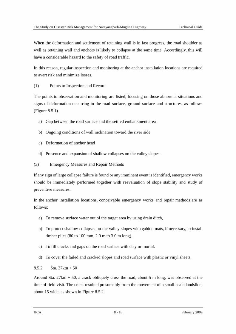
The Study on Disaster Risk Management for Narayangharh-Mugling Highway Technical Guide
JICA 8 - 18 February 2009
When the deformation and settlement of retaining wall is in fast progress, the road shoulder as well as retaining wall and anchors is likely to collapse at the same time. Accordingly, this will have a considerable hazard to the safety of road traffic.
In this reason, regular inspection and monitoring at the anchor installation locations are required to avert risk and minimize losses.
(1) Points to Inspection and Record
The points to observation and monitoring are listed, focusing on those abnormal situations and signs of deformation occurring in the road surface, ground surface and structures, as follows (Figure 8.5.1).
a) Gap between the road surface and the settled embankment area
b) Ongoing conditions of wall inclination toward the river side
c) Deformation of anchor head
d) Presence and expansion of shallow collapses on the valley slopes.
(3) Emergency Measures and Repair Methods
If any sign of large collapse failure is found or any imminent event is identified, emergency works should be immediately performed together with reevaluation of slope stability and study of preventive measures.
In the anchor installation locations, conceivable emergency works and repair methods are as follows:
a) To remove surface water out of the target area by using drain ditch,
b) To protect shallow collapses on the valley slopes with gabion mats, if necessary, to install timber piles (80 to 100 mm, 2.0 m to 3.0 m long).
c) To fill cracks and gaps on the road surface with clay or mortal.
d) To cover the failed and cracked slopes and road surface with plastic or vinyl sheets.
8.5.2 Sta. 27km + 50
Around Sta. 27km + 50, a crack obliquely cross the road, about 5 m long, was observed at the time of field visit. The crack resulted presumably from the movement of a small-scale landslide, about 15 wide, as shown in Figure 8.5.2.

The Study on Disaster Risk Management for Narayangharh-Mugling Highway Technical Guide
JICA 8 - 19 February 2009
The landslide is in close proximity to the small stream that flows cross the road. Two gabion sabo dams were constructed in the stream on the valley side of the road. The initialization of the small landslide was considered to be due to foundation excavation of the gabion sabo dams.
The small landslide was considered, based on the field visit, to be less likely to reactivate and quickly slide down. However, once sliding down, the right of way would be completely lost. As restoration works, highly costly combination of anchor, retaining wall and embankment would be required.
Figure 8.5.2 Site Present Situation and Points to Inspection
Therefore, ongoing status of the crack should be regularly inspected and monitored for securing the safety of road traffic.
The frequency of regular inspection is the same as that for the anchor installation locations, as described above.
In addition, in the case of emergency, conceivable urgent measures and repair methods are as follows:
a) To remove surface water out of the landslide area,
b) To fill the cracks and gaps on the road surface with clay or mortar,
c) To construct embankment with gabion wall on the toe of the landslide.
8.5.3 Sta. 26km + 700
Around Sta. 26km + 700, a road surface gap of about 2 cm was observed at the time of field visit. In addition, some opening cracks were observed on the side masonry ditch and masonry wall on the hillside.
Mountain side
Road
Sabo dam
Stream
Crack and gap dueto settlementRiver side

The Study on Disaster Risk Management for Narayangharh-Mugling Highway Technical Guide
JICA 8 - 20 February 2009
These structural deformations were considered to be due to the movement of a small-scale landslide, as shown in Figure 8.5.3. The small-scale landside is, however, inactive at present because these deformations are not in progress.
Similar to the small-scale landslide at Sta. 27km + 50, the landslide movement would make the right of way completely lost. Therefore, the ongoing status of the gap and crack on the road surface and masonry wall should be regularly inspected and monitored for securing the safety of road traffic.
Figure 8.5.3 Site Present Situation and Points to Inspection
Further, in case where unusual conditions or ongoing conditions of the deformed structures are observed, e.g. significant settlement on the road surface and obvious opening of cracks on the masonry wall observed, advice for emergency measures should immediately be sought from a geologist or landslide expert.
Conceivable urgent measures and repair methods are as follows:
a) To remove surface water out of the landslide area by installing a drain ditch above the upslope end of the landslide area,
b) To fill the cracks and gaps on the road surface with clay or mortar,
c) To construct retaining concrete wall with anchors on the valley slope of the road.
Mountain sideRoad
2-cm gap River sideSettlement
Cracks Massonry wall
50 m
50 m

APPENDIX 1
INSPECTION FORMAT

Appendix 8-1 Asset Inventory Sheet 1: General InformationRegion Management OfficeRoad nameStation from km m until km m
Date Month Year
PhotographsGeneral View
Portion to which attention should be paid
Location (Distance from Road CenterImplemeted Countermeasures
Assessmentdate
General Description
Central Development Region Bharatpure, ChitwanNarayangharh-Mugling Highway
S.No
Prepared byChecked by

km mkm m
3-1 Front view/ Plane view sketches
3-2 Cross section sketches
Comprehensive Evaluation
S.No.Road NameStation from
Narayangharh-Mugling Highway
Box Culvert
Gabion SpurSurface DrainageHorizontal DrillingBio-Engineering
Retaining WallGabion Check Dam
Concrete Sabo DamGabion Check Dam
Appendix 8-2 Asset Inventory Sheet 2: Evaluation of Existing Countermeasure
Location (Distance from Road Center)
Implemented Countermeasure General Dimension Condition/Rate

km m
4-1 Plan layout of Rehabilitation
No. Unit Quantity Amount (Rs)
1
2
3
4
5
6
7
S.No.Name of planner
Work Unit price (Rs)
Total Cost
Road Name Narayangharh-Mugling HighwayStation from
Rough Cost Estimation
4-2 Section layout
Appendix 8-3 Asset Inventory Sheet 3: Rehabilitation Plan
Remaks on Rehabilitation

S.No. RankLocation Implemented Measures Rehabilitation CostAppendix 8-4 Inspection Result of Countermeasures for Water Induced Disasters

APPENDIX 2
DESIGN EXAMPLES

The Study on Disaster Risk Management for Narayangharh-Mugling Highway Technical Guide
JICA 1 February 2009
DESIGN EXAMPLES
1 Sabo Dam
This section provides an example of sabo dam design, which is based on the following guidelines:
a) Technical Guideline for Debris Flow Control Measures (Tentative), July 2000, Prepared by Sediment Control Division, Sediment Control Department, River Bureau, Ministry of Construction.
b) Technical Standard for the Measures against Debris Flow and Driftwood, August 2007, Prepared by Sediment Control Division, Sediment Control Department, River Bureau, Ministry of Construction.
1.1 Design Conditions and Parameters
The design data and conditions are determined on the basis of site investigation and common engineering practice as shown in Table 1.1.

The Study on Disaster Risk Management for Narayangharh-Mugling Highway Technical Guide
JICA 2 February 2009
Table 1.1 Design Data and Conditions for Sabo Dam Conditions and Parameters Remarks
1. Catchment area (km2) A=0.12 2. Gradient of streambed I=tanθ=1/4.4, θ=12.8o
3. Design rainfall per day (mm/24hr) P24=406.6 P24=305.0
Planning Past
4. Maximum grain size of debris flow (m) d95=1.0 5. Internal friction angle (degree) φ=35 Gravelly sand 6. Density of water (tf/m3) ρw= 1.2 7. Density of debris gravel (tf/m3) ρg = 2.6 8. Volumetric density of accumulated debris Co=0.6 Generally 9. Unit weight in mud of sand and gravel in accumulation We= 8.24 kN/m3 Co(ρg-ρw)
10. Unit weight in mud of sand and gravel in debris flow γf = 5.63 kN/m3 (γd-ρw)
11. Coefficient of earth pressure of sediment accumulation Ce=0.3
12. Unit weight of concrete (kN/m3) Wc=22.56 13. Young’s Modulus of debris gravel (N/m2) E2 = 5.0×109×9.8 14. Poisson’s ratio of debris gravel ν2 = 0.23 15. Young’s Modulus of concrete (N/m2) E1 = 0.1×2.6×109×9.8 Final strength 16. Poisson’s ratio of concrete ν1 = 0.194 17. Allowable bearing capacity (kN/m2) qa = 600 Gravel ground 18. Friction coefficient of wall base and ground fr = 0.6 19. Effective height of dam body (m) He=7.0 20. Height of dam body (m) H= 9.0 21. Discharge coefficient of runoff f =0.75 Steep mountain
1.2 Design Discharge
(1) Calculation of peak discharge of clear water
The peak discharge, Qp, of clear water due to rainfall is calculated as follows:
ArfQ ap ×××=6.3
1
ra : Average rainfall intensity (mm)
In case of no average rainfall intensity available in the project area, the peak discharge, Qp, can be calculated as follow:
32.412.05.1296.3
16.3
1=××=××= ArQ ep m2/s
re : Effective rainfall intensity (mm), which is obtained using the following method:

The Study on Disaster Risk Management for Narayangharh-Mugling Highway Technical Guide
JICA 3 February 2009
606.0)60/
24()24
( 22.0
221.124
AkpfPre ×
××=
5.129606.0)12.060/120
75.024()24
6.406( 22.0
221.1 =
××
×= mm/hr
kp : Coefficient of drainage area (generally, kp = 120)
(2) Calculation of design discharge in consideration of sediment content
The design discharge of a dam is determined by considering the sediment content ratio, using the return period of about 1:100 years of daily rainfall or previous maximum rainfall, whichever is larger.
50% sediment mix is generally added to the peak discharge (Qp) in Japan, the Q, is calculated as follows:
pQQ ×= 5.1 =1.5×4.32 = 6.48 m3/s
1.3 Peak Discharge for debris Flow
(1) Calculation of Volumetric sediment concentration of debris flow
The Volumetric sediment concentration of debris flow, Cd, is calculated below
)tan(tan)(tan
θφρρθρ
−×−×
=wg
wdC
41.0)8.12tan35(tan)12002600(
8.12tan1200=
−×−×
=
(2) Calculation of amount of possible debris flow
The amount of possible debris flow in assumed debris flow area is obtained by estimating the amount of possible debris flows in each branch at upstream of the planning point as shown in Table 1.2.
Table 1.2 Design Data and Conditions for Debris Flow Possible debris flow amount (m3)
zero-order stream 1st-order stream Assumed
debris flow areas Length
(m) Area (m2)
Volume (m3)
Length (m)
Area (m2)
Volume (m3)
Subtotal(m3)
1 180 1.5 270 450 5 2,250 2,5202 260 1.5 390 70 5 350 740

The Study on Disaster Risk Management for Narayangharh-Mugling Highway Technical Guide
JICA 4 February 2009
As shown in the table above, the assumed debris flow area 1 has the biggest amount of possible debris flow.
(3) Calculation of amount of transported debris flow
The amount of transported debris flow, Vdy2, is calculated as follows:
224
3
2 )1
(1
10f
d
d
vdy K
CC
KAPV ×
−×
−××
=
200,2748.0)41.01
41.0(4.01
12.06.406103
=×−
×−
××= m3
Kv : Void ratio (Kv=1-C = Co = 1-0.6 = 0.4)
Kf2 : Runoff revision coefficient, generally 0.1 ≦ Kf2 ≦ 0.5, calculated as follows:
48.005.0)0.212.0(log05.005.0)0.2(log05.0 222 =++=+−= AK f
As calculated above, the amount of possibly transported debris flow at one debris flow event is larger than that of possible debris flow in assumed debris flow area, as follows:
27,200m3 >2,520 m3
Accordingly, the amount of assumed debris flow at one debris flow event is set as Vdqp=2,520m3.
(4) Calculation of peak discharge for debris flow
The peak discharge for debris flow, Qsp, is calculated as follows:
d
dqpsp C
CVQQ 001.001.0
××=∑×=
9.3641.0
6.0520,201.0 =×
×= (m3/s)
1.4 Design Depth for Design Discharge
The design depth of a dam is determined by considering 1) design depth for design discharge, 2) design depth for peak discharge of debris flow and 3) design depth for maximum grain size of debris gravel, whichever is biggest.
(1) Width of crest opening
The width of crest opening is, in principle, over 3.0 m. The width is set to be same as the width of existing streambed, as follows:

The Study on Disaster Risk Management for Narayangharh-Mugling Highway Technical Guide
JICA 5 February 2009
B1 = 5.0 m (B1 : Base width of opening)
(2) Design depth for design discharge
Here the inclination (m2) of opening is 0.5, the discharge of opening is shown in the following figure and calculated as follows:
Figure 1.1 Design Depth for Design Discharge
2/3111 )77.171.0( hBhQ ××+×=
mmh 8.079.01 ≅=
(3) Design depth for peak discharge of debris flow
The design depth of debris flow, h, is calculated using the following equation:
53
5.0)(sin ⎭⎬⎫
⎩⎨⎧
×
×=
×=
θBQn
VBQ
h sp
df
sp =1.43 m =1.5m
B : Width of debris flow, B = B1 = 5.0 m (Base width of opening) Vdf: Flow velocity of debris flow (m3/s) n : Coefficient of roughness at apron, n = 0.1 θ: Planning inclination of sediment deposition at riverbed, θ= 8.62 degrees, I=1/4.4
×2/3=1/6.6)
43.159.36
×=
×=
hBQ
V spdf =5.16 m/s
(4) Determination of design depth for opening
Hc
B2
1 B1
h1
h2
1:m2

The Study on Disaster Risk Management for Narayangharh-Mugling Highway Technical Guide
JICA 6 February 2009
The design depth of opening is determined to be 1.5 m on the basis of the calculation above, as listed below:
a) Design depth for design discharge: h1 = 0.8m b) Design depth for peak discharge of debris flow : h = 1.5 m c) Maximum grain size of debris gravel: d95=1.0m
1.5 Height of Crest Opening
(1) Free board for design discharge
The freeboard depends on the design flood discharge, as shown in Table 1.3.
Table 1.3 Free Board for Design Discharge
Discharge (m3/s) Freeboard (m) Remarks Less than 200 0.6 200 – 500 0.8
500 or over 1.0 The freeboard is set out as 0.8 m because of discharge of 200 to 500m3/s.
(2) Height of crest opening
The sabo dam is designed pass through debris flow, and the height of crest opening, Hc, is thus determined to be the sum of design depth, h, of debris flow and freeboard, ∆H, as follows
Hc = h + ΔH = 1.5 m + 0.8 m = 2.3 m
(3) Section of crest opening
The section of crest opening is, on the basis of the above calculation results, set and shown in Figure 1.2.
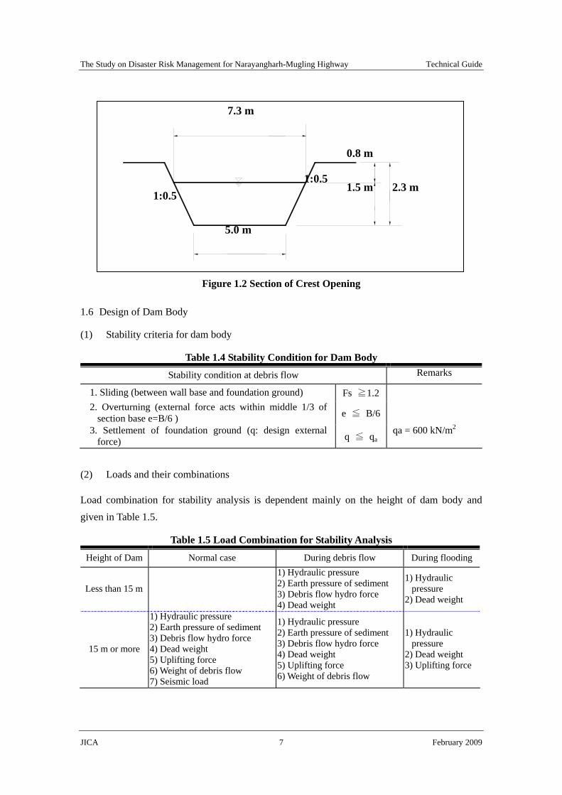
The Study on Disaster Risk Management for Narayangharh-Mugling Highway Technical Guide
JICA 7 February 2009
Figure 1.2 Section of Crest Opening
1.6 Design of Dam Body
(1) Stability criteria for dam body
Table 1.4 Stability Condition for Dam Body
Stability condition at debris flow Remarks
1. Sliding (between wall base and foundation ground) Fs ≧1.2
2. Overturning (external force acts within middle 1/3 of section base e=B/6 ) e ≦ B/6
3. Settlement of foundation ground (q: design external force) q ≦ qa
qa = 600 kN/m2
(2) Loads and their combinations
Load combination for stability analysis is dependent mainly on the height of dam body and given in Table 1.5.
Table 1.5 Load Combination for Stability Analysis
Height of Dam Normal case During debris flow During flooding
Less than 15 m
1) Hydraulic pressure 2) Earth pressure of sediment 3) Debris flow hydro force 4) Dead weight
1) Hydraulic pressure
2) Dead weight
15 m or more
1) Hydraulic pressure 2) Earth pressure of sediment 3) Debris flow hydro force 4) Dead weight 5) Uplifting force 6) Weight of debris flow 7) Seismic load
1) Hydraulic pressure 2) Earth pressure of sediment 3) Debris flow hydro force 4) Dead weight 5) Uplifting force 6) Weight of debris flow
1) Hydraulic pressure
2) Dead weight 3) Uplifting force
2.3 m 1:0.5
0.8 m
1.5 m
5.0 m
7.3 m
1:0.5

The Study on Disaster Risk Management for Narayangharh-Mugling Highway Technical Guide
JICA 8 February 2009
(3) Calculation of external force (loads) during flooding
The model of external forces is shown in Figure 1.3
Figure 1.3 Model of External Forces during Flooding
1) Dead weight
VWW c ×=
Where:
W : Weight of dam of unit width Wc : Unit weight of concrete (kN/m3) (Wc=22.56 kN/m3) V : Volume of typical cross section of unit width (m)
2) Hydrostatic pressure
ww hP ×= ρ
Where:
P : Hydrostatic pressure (kN/m2)
ρw : Unit weight of water (ρw = 11.77 kN/m3) hw : Water depth (m)
3) Load combination
b) Hydrostatic pressure
PV1
PV3 PV2 D.F.L
b1=3m
h3=0.8m
H=9m n:1
W3 W2
W1 m:1 PH2
Basic point of calculation
PH1
a) Dead weight
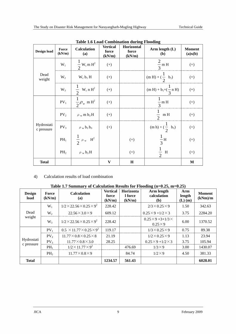
The Study on Disaster Risk Management for Narayangharh-Mugling Highway Technical Guide
JICA 9 February 2009
Table 1.6 Load Combination during Flooding
Design load Force (kN/m)
Calculation (a)
Vertical force
(kN/m)
Horizontal force
(kN/m)
Arm length (L) (b)
Moment(a)x(b)
W1 21
Wc m H2 (+) 32
m H (+)
W2 Wc b1 H (+) (m H) + (21
b1) (+) Dead weight
W3 21
Wc n H2 (+) (m H) + b1+(31
n H) (+)
PV1 wρ21
m H2 (+) 31
m H (+)
PV2 ρw m h3 H (+) 21
m H (+)
PV3 ρw b1 h3 (+) (m h) + (21
b1) (+)
PH1 21ρw H2 (+)
31
H (+)
Hydrostatic pressure
PH2 ρw h3 H (+) 21
H (+)
Total V H M
4) Calculation results of load combination
Table 1.7 Summary of Calculation Results for Flooding (n=0.25, m=0.25) Design
load Force
(kN/m) Calculation
(a)
Vertical force
(kN/m)
Horizontal force (kN/m)
Arm length calculation
(b)
Arm length (L) (m)
Moment (kNm)/m
W1 1/2×22.56×0.25×92 228.42 2/3×0.25×9 1.50 342.63
W2 22.56×3.0×9 609.12 0.25×9 +1/2×3 3.75 2284.20 Dead weight
W3 1/2×22.56×0.25×92 228.42 0.25×9 +3+1/3×0.25×9
6.00 1370.52
PV1 0.5 ×11.77×0.25×92 119.17 1/3×0.25×9 0.75 89.38 PV2 11.77×0.8×0.25×8 21.19 1/2×0.25×9 1.13 23.94 PV3 11.77×0.8×3.0 28.25 0.25×9 +1/2×3 3.75 105.94 PH1 1/2×11.77×92 476.69 1/3×9 3.00 1430.07
Hydrostatic pressure
PH2 11.77×0.8×9 84.74 1/2×9 4.50 381.33
Total 1234.57 561.43 6028.01

The Study on Disaster Risk Management for Narayangharh-Mugling Highway Technical Guide
JICA 10 February 2009
(4) Stability analysis (during flood)
1) Analysis against sliding
43.56157.12346.0 ×
=×
=H
VfrFs =1.32>1.2, Therefore OK.
2) Analysis against overturning
88.457.123401.6028
===VMX
B=2.25+3.00+2.25=7.50, Then, (B/3=2.5) <(X=4.88) < (2B/3=5.00), Therefore OK.
3) Analysis against allowable bearing capacity of foundation
13.150.72188.4
21
=×−=−= BXe
⎭⎬⎫
⎩⎨⎧ ×±×= )6(1
Be
BVq
⎭⎬⎫
⎩⎨⎧ ×+×=
50.713.16(1
50.757.1234
maxq =313.42kN/m2 <qa=600kN/m2, Therefore OK.
⎭⎬⎫
⎩⎨⎧ ×−×=
50.713.16(1
50.757.1234
minq =15.80kN/m2 >0 kN/m2, Therefore OK.
(5) Calculation of external force (loads) during debris flow
The model of external forces is shown in Figure 1.4.
Figure 1.4 Model of External Forces during Debris Flow
Basic point of calculation
b1
σ 1 σ 2
h
H
b) Earth pressure of sediment accumulation
PeH2
PeH1
nH + b1 + mH
nH b1 mH
m : 1
n :1
PV2PV3
H W3
W2
W1 PH2
PH1
c) Hydrostatic pressure
PV1
a) Dead weight

The Study on Disaster Risk Management for Narayangharh-Mugling Highway Technical Guide
JICA 11 February 2009
1) Dead weight
VWW c ×=
Where:
W : Weight of dam of unit width Wc : Unit weight of concrete (kN/m3) V : Volume of typical cross section of unit width (m)
2) Debris flow hydro force
22 16.511.18.94.17
××=×= dfd Vh
gF
γ = 52.5 kN/m2
Where:
γd : Unit weight of debris flow (kN/m3) g : Gravity of acceleration (9.8 m/s2) h : Design depth of debris flow (m) (assumed h=1.11m) Vdf : Velocity of debris flow (m/s) (Vdf = 5.16m/s see above)
8.9)41.01(120041.02600())1(( ×−×+×=×−×+×= gCdCd wgd ρργ
17385 N/m3= 17.4 kN/m3
Where:
γd : Unit weight of debris flow (kN/m3) g : Gravity of acceleration (9.8 m/s2)
ρg : Density of debris gravel (=2.6 tf/m3) ρw : Density of water (=1.2 tf/m3) Cd : Volumetric sediment concentration of debris flow (Cd = 0.41 see above)
3) Earth pressure of debris deposits
eee hWP ×=
Where:
Pe : Earth pressure (kN/m) We : Unit weight of sediments sedimentation (kN/m3) he : Depth of debris deposits (m)

The Study on Disaster Risk Management for Narayangharh-Mugling Highway Technical Guide
JICA 12 February 2009
4) Load combination
Table 1.8 Load Combination during Debris Flow
Design load Symbol Calculation
(a)
Vertical force (V)
Horizontal force (H)
Arm length (L) (b)
Moment (a)x(b)
W1 21
Wc m H2 (+) 32
m H (+)
W2 Wc b1 H (+) (mH)+(21
b1) (+) Dead weight
W3 21
Wc n H2 (+) mH+b1+ 31
nH (+)
PV1 21ρw m (H-h)2 (+)
31
m (H-h) (+)
PH1 21ρw (H-h)2 (+)
31
(H-h) (+) Hydrostatic pressure
PH2 ρw h (H-h) (+) 21
(H-h) (+)
PeV1 21
We m (H-h)2 (+) 31
(H-h) m (+)
PeH1 21
m We (H-h)2 (+) 31
(H-h) (+)
Weight of debris flow
PeH2 eC fγ h (H-h)2 (+)
21
(H-h) (+)
Pd1 dγ h m (H-h) (+) 21
(H-h) m (+) Earth
pressure Pd2
21
dγ m h2 (+) (H-h) m+3h
m (+)
Debris-flow hydro
force F (+)
21
h+(H-h) (+)
Total V H M
Note: Symbols is the same as those shown in figure above.
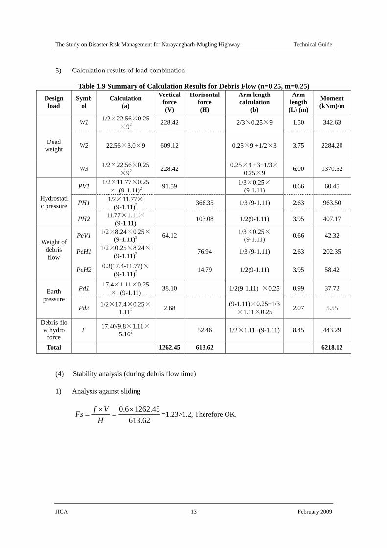
The Study on Disaster Risk Management for Narayangharh-Mugling Highway Technical Guide
JICA 13 February 2009
5) Calculation results of load combination
Table 1.9 Summary of Calculation Results for Debris Flow (n=0.25, m=0.25)
Design load
Symbol
Calculation (a)
Vertical force (V)
Horizontal force (H)
Arm length calculation
(b)
Arm length (L) (m)
Moment (kNm)/m
W1 1/2×22.56×0.25×92
228.42 2/3×0.25×9 1.50 342.63
W2 22.56×3.0×9 609.12 0.25×9 +1/2×3 3.75 2284.20 Dead weight
W3 1/2×22.56×0.25×92
228.42 0.25×9 +3+1/3×0.25×9
6.00 1370.52
PV1 1/2×11.77×0.25× (9-1.11)2
91.59 1/3×0.25×(9-1.11) 0.66 60.45
PH1 1/2×11.77×(9-1.11)2 366.35 1/3 (9-1.11) 2.63 963.50
Hydrostatic pressure
PH2 11.77×1.11×(9-1.11) 103.08 1/2(9-1.11) 3.95 407.17
PeV1 1/2×8.24×0.25× (9-1.11)2 64.12 1/3×0.25×
(9-1.11) 0.66 42.32
PeH1 1/2×0.25×8.24× (9-1.11)2 76.94 1/3 (9-1.11) 2.63 202.35
Weight of debris flow
PeH2 0.3(17.4-11.77)×
(9-1.11)2 14.79 1/2(9-1.11) 3.95 58.42
Pd1 17.4×1.11×0.25× (9-1.11)
38.10 1/2(9-1.11) ×0.25 0.99 37.72 Earth pressure
Pd2 1/2×17.4×0.25×1.112 2.68 (9-1.11)×0.25+1/3
×1.11×0.25 2.07 5.55
Debris-flow hydro
force F 17.40/9.8×1.11×
5.162 52.46 1/2×1.11+(9-1.11) 8.45 443.29
Total 1262.45 613.62 6218.12
(4) Stability analysis (during debris flow time)
1) Analysis against sliding
62.61345.12626.0 ×
=×
=H
VfFs =1.23>1.2, Therefore OK.

The Study on Disaster Risk Management for Narayangharh-Mugling Highway Technical Guide
JICA 14 February 2009
2) Analysis against overturning
91.445.126212.6218
===VMX
B=2.25+3.00+2.25=7.50, Then, (B/3=2.4)<(X=4.91)<(2B/3=5.00), Therefore OK.
3) Analysis against allowable bearing capacity of foundation
16.150.72191.4
21
=×−=−= BXe
⎭⎬⎫
⎩⎨⎧ ×±×= )6(1
Be
BVq
⎭⎬⎫
⎩⎨⎧ ×+×=
50.716.16(1
50.745.1262
maxq =324.53kN/m2 <qa=600kN/m2, Therefore OK.
⎭⎬⎫
⎩⎨⎧ ×−×=
50.716.16(1
50.745.1262
minq =12.12 kN/m2 >0 kN/m2, Therefore OK.

The Study on Disaster Risk Management for Narayangharh-Mugling Highway Technical Guide
JICA 15 February 2009
2 Gravity Type Retaining Concrete Wall
This Section provides an example of gravity type retaining concrete wall.
2.1 Design Conditions and Parameters
The design data and conditions are determined on the basis of site investigation and common engineering practice as shown Table 2.1
Table 2.1 Design Data and Conditions for Retaining Wall Conditions and Parameters Remarks
1. Wall height (m) H = 3.00 m 2. Crest width (m) B1=0.40 m 3. Front slope (V:H) V:H=1:0.2 4. Back slope (V:H) V:H=1:0.4 5. Base width (m) B = 2.20 m 6. Embankment height (m) H0=2.0m 7. Embankment slop (V:H) V:H=1:1.5 β=33.69 degrees 8. Unit weight of backfilling material (kN/m3) γ=20 kN/m3 Gravely soil 9. Internal friction angle of backfilling material (degree) φ=35 degrees Gravely soil 10. Design standard strength of concrete ((N/mm2) σck = 18 N/mm2 11. Unit weight of concrete (kN/m3) γc=23 kN/m3 12. Friction Coefficient of Structure and Foundation μ= 0.6 Gravely soil ground13. Allowable bearing capacity of ground (kN/m2) qa = 300 kN/m2 N=30 14. surcharge load (kN/m2) q = 10 kN/m2
Figure 2.1 Model of Design Load and Conditions
q=10kN/m2
Gravely soilφ=35o
Gravely soilN=30
B=2.20m
B1=0.40mH1=3.0m
H=3.0m
β=33.69oH0=2.0m
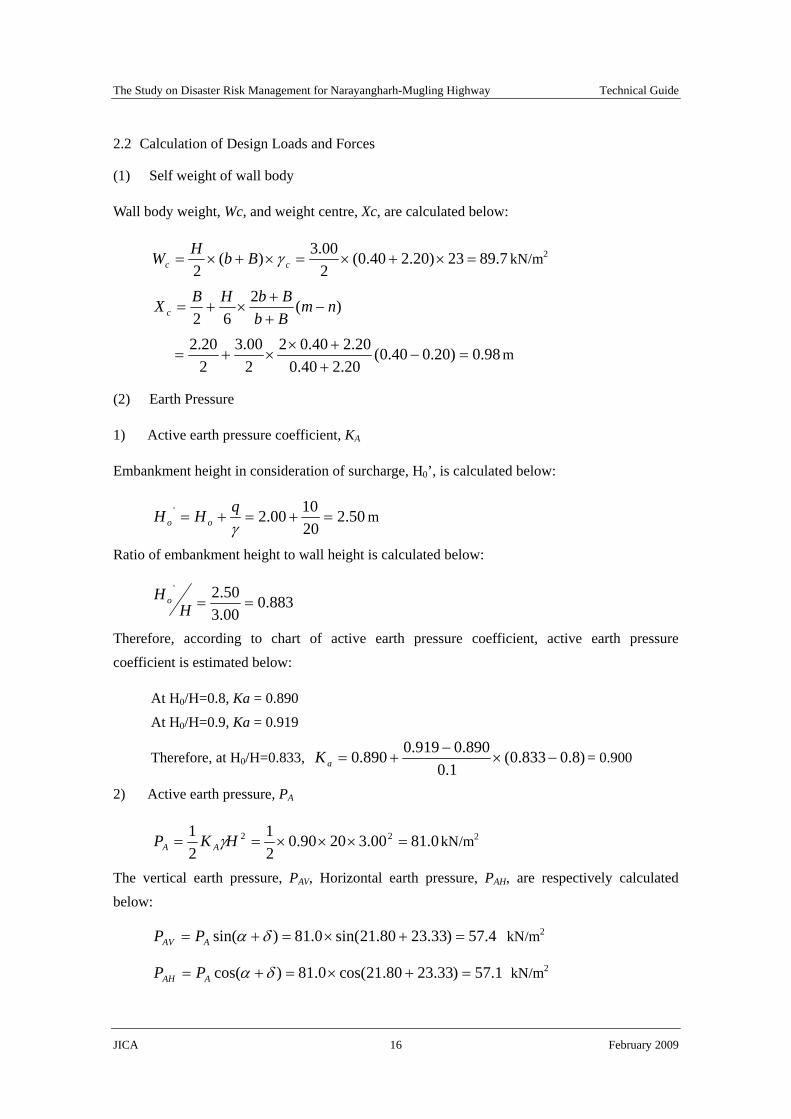
The Study on Disaster Risk Management for Narayangharh-Mugling Highway Technical Guide
JICA 16 February 2009
2.2 Calculation of Design Loads and Forces
(1) Self weight of wall body
Wall body weight, Wc, and weight centre, Xc, are calculated below:
7.8923)20.240.0(200.3)(
2=×+×=×+×= cc BbHW γ kN/m2
)(262
nmBbBbHBX c −
++
×+=
98.0)20.040.0(20.240.0
20.240.02200.3
220.2
=−+
+××+= m
(2) Earth Pressure
1) Active earth pressure coefficient, KA
Embankment height in consideration of surcharge, H0’, is calculated below:
50.2201000.2' =+=+=
γqHH oo m
Ratio of embankment height to wall height is calculated below:
883.000.350.2'
==HH o
Therefore, according to chart of active earth pressure coefficient, active earth pressure coefficient is estimated below:
At H0/H=0.8, Ka = 0.890 At H0/H=0.9, Ka = 0.919
Therefore, at H0/H=0.833, )8.0833.0(1.0
890.0919.0890.0 −×−
+=aK = 0.900
2) Active earth pressure, PA
0.8100.32090.021
21 22 =×××== HKP AA γ kN/m2
The vertical earth pressure, PAV, Horizontal earth pressure, PAH, are respectively calculated below:
4.57)33.2380.21sin(0.81)sin( =+×=+= δαAAV PP kN/m2
1.57)33.2380.21cos(0.81)cos( =+×=+= δαAAH PP kN/m2

The Study on Disaster Risk Management for Narayangharh-Mugling Highway Technical Guide
JICA 17 February 2009
Where:
Wall fraction angle, δ=2/3×φ=2/3×35=23.330 Angle formed by the back surface of wall and vertical place, α=tan-1n=tan-10.4=21.800
3) Location of earth pressure resultant, YA, XA
00.1300.3
3===
HYA m
80.100.140.020.2 =×−=×−= AA YnBX m
(3) Load combination
Table 2.2 Load Combination for Retaining Wall Vertical Horizontal Resultant location (m) Moment (kN・m/m)
Loading V(kN/m) H(kN/m) x y V×x H×y
Wall Weight 89.7 0.00 0.98 - 87.9 0.00 Earth pressure 57.4 57.1 1.80 1.00 103.3 57.1
Total 147.1 57.1 - - 191.2 57.1
2.3 Stability Analysis for Retaining Wall
(1) Stability against sliding
55.11.57
6.01.147=
×=
∑×∑
=H
VFs µ>1.5, Therefore, OK.
(2) Stability against overturning
Acting point of resultant, d, is calculated below:
91.01.147
1.572.191=
−=
∑×∑−×∑
=V
yHxVd m
Acting range of resultant, e, is calculated below:
36.06
19.091.0220.2
2=≤=−=−=
BdBe , Therefore, OK.
(3) Stability against bearing capacity of ground
)61(2 B
eBVq ±
∑=

The Study on Disaster Risk Management for Narayangharh-Mugling Highway Technical Guide
JICA 18 February 2009
)20.2
19.061(20.2
1.147)61(2max
×+=+
∑=
Be
BVq
=102kN/m2 < qa=300 kN/m2, Therefore, OK.
)20.2
19.061(20.2
1.147)61(2min
×−=−
∑=
Be
BVq
=32kN/m2 > 0 kN/m2, Therefore, OK.