chapter 6.—coal seam degasification · 79 seam gas content. based on their gas contents, coal...
TRANSCRIPT

77
CHAPTER 6.—COAL SEAM DEGASIFICATION
By Pramod C. Thakur, Ph.D.1 In This Chapter
Origins of coalbed methane Reservoir properties of coal seams Thresholds for coal seam degasification Methane emissions in mines Methane drainage techniques How to transport gas safely in mine pipelines
and Economics of coal seam degasification
Recommended publications on coal seam degasification are Gas Control in Underground Coal Mining [Creedy et al. 1997], Coalbed Methane Extraction [Davidson et al. 1995], and Methane Control for Underground Coal Mines [Diamond 1994].
ORIGINS OF COALBED METHANE AND RESERVOIR PROPERTIES OF COAL SEAMS
Origins of coalbed methane. Coal seams form over millions of years by the biochemical decay and metamorphic transformation of plant materials. This coalification process produces large quantities of byproduct gases, such as methane and carbon dioxide. The amount of these byproducts increases with the rank of coal. It is the highest for anthracite, where for every ton of coal nearly 1,900 lb of water, 2,420 lb (20,000 ft3) of carbon dioxide, and 1,186 lb (27,000 ft3) of methane are produced [Hargraves 1973]. Most of these gases escape to the atmosphere during the coalification process, but a small fraction is retained in the coal. The amount of gas retained in the coal depends on a number of factors, such as the rank of coal, the depth of burial, the type of rock in the immediate roof and floor, local geologic anomalies, and the tectonic pressures and temperatures prevalent at that time. The gases are contained under pressure and mainly adsorbed on the surface of the coal matrix, but a small fraction of gases is also present in the fracture net-work of the coal. Methane is the major component of gases in coal, comprising 80%–90% or more of the total gas volume. The balance is made up of ethane, propane, butane, carbon dioxide, hydrogen, oxygen, and argon.
1Manager, Coal Seam Degasification, CONSOL Energy, Inc., Morgantown, WV.

78
Methane is released into each mine airway from the coal seam as mining proceeds. Large volumes of air, sometimes as much as 20 tons of air for each ton of coal mined, is circulated constantly to dilute and carry methane away from coal mines. Methane is a colorless, odorless, combustible gas that forms an explosive mixture with mine air in the concentration range of 5%–15% by volume. The maximum concentration of methane in mine air is restricted by law to 1%–1.25% in all major coal-producing countries. Nevertheless, methane-air explosions are quite common even today. Table 6–1 shows a list of major coal mine explosions since 1970 in the United States. In these 13 explosions, 167 lives were lost despite coal seam degasification taking place in some mines.
Table 6–1.—Major coal mine explosions in the United States, 1970–present
Year Mine and location Deaths
2006......... Sago Mine, Tallmansville, WV ........................... 12 2001......... Blue Creek No. 5 Mine, Brookwood, AL ............ 13 1992......... No. 3 Mine, Norton, VA ...................................... 8 1989......... William Station No. 9 Mine, Wheatcroft, KY....... 10 1983......... McClure No. 1 Mine, McClure, VA ..................... 7 1982......... No. 1 Mine, Craynor, KY .................................... 7 1981......... No. 21 Mine, Whitwell, TN.................................. 13 1981......... No. 11 Mine, Kite, KY......................................... 8 1981......... Dutch Creek No. 1 Mine, Redstone, CO............ 15 1980......... Ferrell No. 17 Mine, Uneeda, WV ...................... 5 1976......... Scotia Mine, Oven Fork, KY............................... 26 1972......... Itmann No. 3 Mine, Itmann, WV......................... 5 1970......... No. 15 and 16 Mines, Hyden, KY....................... 38
Coal has been mined throughout the world for hundreds of years, and the history of coal mining is replete with mine explosions and consequent loss of lives. Even today, 60 countries around the world mine about 5 billion tons of coal annually with more than 10,000 fatalities per year. Before 1950, when coal seam degasification was generally unknown and ventilation was the only method of methane control, mine explosions in the United States were much more disastrous with a very high number of fatalities. To mitigate this problem, in many instances, mine ventila-tion can be supplemented by coal seam degasification prior to mining and even after mining. Reservoir properties of coal seams. Coal seam degasification techniques to be used in a mine depend on the reservoir properties of the coal seams being mined. Good methane control plan-ning depends on accurate information on the reservoir properties of the coal seam and the total gas emission space created by the mining process. Reservoir properties governing the emission of methane from coal seams can be divided into two groups: (1) properties that determine the capacity of the seam for total gas production, e.g., adsorbed gas and porosity, and (2) properties that determine the rate of gas flow, e.g., permeability, reservoir pressure, and diffusivity of coal. The reservoir properties are highly dependent on the depth and rank of the coal seam. The most important of these properties is the seam gas content.

79
Seam gas content. Based on their gas contents, coal seams can be classified as mildly gassy, moderately gassy, and highly gassy, as shown in Table 6–2.
Table 6–2.—Gassiness of coal seams
Category 1Depth, ft Gas content of coal, ft3/ton
Mildly2 gassy..................... <600 <100 Moderately gassy ............. 600–1,200 100–300 Highly gassy ..................... 1,200–3,000 300–700 1Depth figures are for high-volatile bituminous coals. 2The term “mildly” is not intended to imply that such mines are free from gas problems. The potential for gas problems involves many factors, not just the coal gas content. If an area of a mildly gassy mine were inadequately ventilated, it could easily attain an atmosphere in the explosive range. It is likely that many of the mines with explosion fatali-ties shown in Table 6–1 were in mildly gassy coals.
By definition, seam gas content is the amount of gas contained in a ton of coal. It includes both adsorbed gases and gases in the fracture matrix. Formerly, gas content of a coal seam or the gassiness of a coal seam was measured by the specific emission of methane from the mine, expressed as the volume of methane emitted from the mine per ton of coal produced. Although a rough correlation exists between specific emission and actual gas content of coal, it is not very reliable nor can it be used effectively for forecasting.2 Today, gas content of a coal seam is best measured directly [Diamond and Schatzel 1998]. If the reservoir pressure is known, an indirect estimate of gas content can also be obtained by Langmuir’s equation [Langmuir 1918] for mono-layer adsorption:
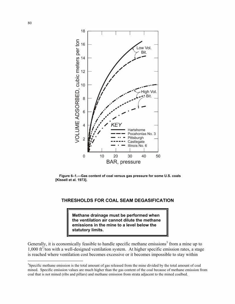
)1/( BPVmBPV += , where V is the estimated gas content of coal, Vm is the volume of gas for full saturation of coal, B is a characteristic constant of the coal seam, and P is the reservoir pressure. For U.S. coalbeds, the reservoir pressure is roughly correlated with the depth of the coal seam [Thakur and Davis 1977] and is estimated at 0.303 psi/ft, or roughly 70% of the hydrostatic head. Since coal seams and gas in coal are formed together, it is a misnomer to call a coal seam nongassy. All coal seams are gassy by definition, but they vary in their degree of gassiness, i.e., gas content per ton of coal. The depth of a coal seam and its rank are good indicators of its gassiness, but direct measurement of gas content is highly recommended. Figure 6–1 shows the gas content of coal versus gas pressure for some U.S. coals [Kissell et al. 1973]. Both the type of coal and the gas pressure are important. 2See Figure 1–5 in Chapter 1.
80
Figure 6–1.—Gas content of coal versus gas pressure for some U.S. coals [Kissell et al. 1973].
THRESHOLDS FOR COAL SEAM DEGASIFICATION
Methane drainage must be performed when the ventilation air cannot dilute the methane emissions in the mine to a level below the statutory limits.
Generally, it is economically feasible to handle specific methane emissions3 from a mine up to 1,000 ft3/ton with a well-designed ventilation system. At higher specific emission rates, a stage is reached where ventilation cost becomes excessive or it becomes impossible to stay within 3Specific methane emission is the total amount of gas released from the mine divided by the total amount of coal mined. Specific emission values are much higher than the gas content of the coal because of methane emission from coal that is not mined (ribs and pillars) and methane emission from strata adjacent to the mined coalbed.

81
statutory methane limits with mine ventilation alone. However, with a well-planned methane drainage system and a well-designed ventila-tion system, even highly gassy mines with specific methane emissions in excess of 4,000 ft3/ton can be safely operated. In some mines, there is often a choice regarding how much methane should be drained and how much should be handled by mine ventilation air. Figure 6–2 shows a generalized optimum point. The actual optimum point depends on a number of factors, including the rate of mining, size of longwall panel, specific methane emission, and cost of ventilation and methane drainage. Advantages of coal seam degasification can be summarized as follows:
1. Reduced methane concentrations in the mine air, leading to improved safety. 2. Reduced air requirements and corresponding savings in ventilation costs. 3. Faster advance of development headings and economy in the number of airways. 4. Improved coal productivity. 5. Additional revenue from the sale of coal mine methane. 6. Additional uses of degasification boreholes, such as water infusion to control respirable
dust. 7. Advance exploration of coal seams to locate geological anomalies in the longwall panel.
METHANE EMISSIONS IN MINES Underground mining is done in two phases: (1) development and (2) pillar extraction. Develop-ment work involves the drivage of a network of tunnels (entries) into the coal seam to create a large number of pillars or longwall panels to be mined later. This drivage is usually done with a continuous mining machine. This machine cuts and loads coal into a shuttle car, which in turn hauls and dumps the coal onto a moving belt. The coal travels out of mines on a series of belts and is finally brought to the surface via a slope or shaft. Figure 6–3 shows a typical longwall panel layout in a U.S. coal mine. All methane produced during the development phase of mining is from the coal seam being mined. Methane is emitted at the working face as well as in the previously developed areas. All emitted methane is mixed with ventilation air, diluted to safe levels, and discharged on the sur-face. Methane drainage during or prior to development becomes necessary if the development headings will experience a high rate of methane emissions. This is called premining methane drainage. Horizontal drilling of longwall panels prior to mining also falls into this category.
Figure 6–2.—Generalized optimum point for methane drainage, shown here at 70%.

82
The second phase of underground mining involves complete or partial extraction of the coal pillars. Smaller pillars are extracted by con-tinuous mining machines by split-ting them into even smaller pillars. Larger panels of coal (up to 1,000 ft by 10,000 ft or more) are extracted by the longwall method of mining. In either case, the mined coal produces methane. In addition, extracting these pillars or longwall panels causes the overlying strata to subside4 and the underlying strata to heave. The ventilated mine work-ings constitute a natural pressure sink, into which methane flows from the entire disturbed area, or what is known as the gas emission space. Figure 6–4 shows the limits of the gas emission space as sug-gested by four different authors [Lidin 1961; Thakur 1981; Winter 1975; Gunther and Bélin 1967]. The gas emission space may extend to 270 ft below the coal seam being mined and approximately 1,000 ft above it. The gob methane emission rate mainly depends on the rate of long-wall advance, the geology, the size of the longwall panel, and the gas content and thickness of any coal seams in the gas emission space.
4In the United States, the subsided region is called a gob.
Figure 6–3.—Simplified illustration of a typical longwall panel layout in a U.S. coal mine. Ventilation controls are not shown.
Figure 6–4.—Limits of the gas emission space.

83
METHANE DRAINAGE TECHNIQUES
The ultimate goal of coal seam degasification should be to reduce the gas content of the coal seam below 100 ft3/ton prior to mining and capture at least 50%, preferably 75%, of the postmining emission.
Various methane drainage techniques are used to capture the gas from the gob so that the mine ventilation air does not have to handle all of it. Depending on the magnitude of the problem, methane drainage can be performed prior to mining, known as premining methane drainage. Methane drainage can also be performed during mining and after the area is completely mined out and sealed. These two stages are generally grouped together as postmining methane drainage. Premining methane drainage. Techniques for premining drainage can be broadly classified into four categories:
1. Horizontal in-seam boreholes 2. In-mine vertical or inclined (cross-measure) boreholes in the roof and floor 3. Vertical wells that have been hydraulically fractured (so-called frac wells) 4. Short-radius horizontal boreholes drilled from surface
1. Horizontal in-seam boreholes: Early work in premining methane drainage was done with short horizontal in-seam boreholes [Spindler and Poundstone 1960]. Figure 6–5 shows the two most commonly used variations of degasification with in-seam horizontal boreholes. Success of the technique is predicated on good coalbed permeability (≥5 mD). The horizontal drilling tech-nique and its application to degas coal seams are well-documented in published literature [Thakur and Davis 1977; Thakur and Poundstone 1980; Thakur et al. 1988]. In highly perme-able coal seams, e.g., the Pittsburgh Seam of the Appalachian Basin, nearly 50% of the in situ gas can be removed by this technique prior to mining. The major drawback of this technique is that only about 6 months to a year—the time between development and longwall extraction—is available for degasification.
Figure 6–5.—Longwall panel methane drainage.

84
2. In-mine inclined or vertical boreholes: Short vertical or long inclined boreholes have been drilled from an existing mine (or roadways expressively driven for this purpose) to intersect other coal seams in the gas emission space, allowing for the seams to be degassed prior to min-ing. Again, success depends on high permeability. A far better way to degas these coal seams lying in close proximity to each other is to use vertical frac wells. 3. Vertical frac wells: Vertical frac wells are ideally suited to highly gassy, deep, low-permeability coal seams where it takes several years prior to mining to adequately degas the coal. These wells are drilled from the surface on a grid pattern over the entire property or only on longwall panels to intersect the coal seam to be mined in the future. Vertical wells drilled into the coal seam seldom produce measurable amounts of gas without hydraulic stimulation. High-pressure water (or other fluids) with sand are pumped into the coal seam to create fractures (Figure 6–6). The fluid (water) is then pumped out, but the sand remains, keeping the fractures open for gas to escape to the well bore. Under ideal conditions, if the vertical frac wells are drilled more than 5–10 years in advance of mining, 60%–70% of the methane in the coal seam can be removed prior to mining. Vertical frac wells have been very successful in the Appalachian and San Juan Coal Basins of the United States. They have also been attempted in the United Kingdom, Germany, Poland, China, and Australia, but met with only limited success. Major reasons for the lack of success abroad are (1) cost and (2) lack of sufficient permeability, which are further explained below.
1. The cost of drilling and hydrofracing a well in Europe and Australia is typically three times the cost in the United States. The cost of permitting and site preparation is also higher. In many countries, the drilling and hydrofracing equipment are not conveniently available.
Figure 6–6.—Premining methane drainage from surface.

85
2. Lower permeability (<1 mD) of many European, Asian, and Australian coal seams con-tributes to the limited success of frac wells. Even well-designed and well-executed frac jobs in the Bowen Basin of Australia were ineffective. A solution to this problem may lie in “gas flooding,” i.e., injection of an inert gas such as nitrogen or carbon dioxide to drive methane out [Puri and Yee 1990]. Increased methane production is, however, obtained with an increase in the inert gas content of the produced gas. This may affect the market-ing of produced gas adversely.
4. Short-radius horizontal boreholes: In coal seams with high permeability, methane drainage can be performed with boreholes drilled vertically from the surface and then turned through a short radius to intersect the coal seam horizontally. The horizontal extension can be up to 3,000 ft. Methane then flows from the coal seam under its own pressure, as shown in Figure 6–6. The technique is well-proven in oil fields, but it has found a very limited application in coal mines for two reasons:
• Cost: A short-radius borehole drilled vertically to a depth of 1,000 ft and horizontally extended to 3,000 ft may cost up to $500,000.
• Water accumulation in the horizontal borehole: As can be seen in Figure 6–6, any water accumulation in the horizontal leg of the borehole will seriously inhibit gas production. A solution may lie in deepening the vertical leg below the coal seam being drilled and installing a dewatering pump in it, as is commonly done for vertical frac wells.
Of the above four techniques, vertical frac wells have been the most effective option for pre-mining degasification of most coal seams. Vertical frac wells also allow access to all coal seams in the gas emission space for predrainage. Such access becomes necessary in highly gassy mines in order to achieve high productivity. The only possible exception is for shallower, very permeable coal seams where in-mine drilling is sufficient and more economical. In shallow formations, the fracture system created by hydrofracing is like a horizontal pancake and is not very productive because the fracture system does not extend far enough from the borehole.5 Strong6 roof and floor are also necessary to contain the fracture system within the coal seam. Recently, short-radius horizontal boreholes drilled from the surface have been used to recover methane from permeable coalbeds. In the future, carbon dioxide flooding may be used. Postmining methane drainage. Techniques for postmining drainage can be broadly classified into four categories:
1. The packed cavity method and its variants 2. The cross-measure borehole method 3. The superjacent method 4. The vertical gob well method
5The ideal fracture is vertical, entirely within the coal, just a few inches wide, and extends upwards of 1,000 ft from the borehole. 6A roof with rock compressive strength over 10,000 psi.

86
1. Packed cavity method and its variants: This technique is used mainly in Russian coal mines. Early methods of methane control consisted of simply isolating the worked-out area in the mine using packed walls, partial or complete stowing, and plastic sheets or massive stoppings. A net-work of pipeline that passed through these isolation barriers was laid in the gob, and methane was drained using vacuum pumps. Lidin [1961] reviewed several variants of this technique. Figures 6–7 and 6–8 show typical layouts for caving and partially stowed longwall gobs. Methane capture ratios achieved in practice are shown in Table 6–3. The ratios generally seem to improve in going from caving (20%–40%) to fully stowed longwall gobs (60%–80%). In Figure 6–7, the gate roads are protected by a packed wall against the gob. Pipelines are laid through the packed wall to reach nearly the center line of the gob, then manifolded to a larger-diameter pipe in the gate road. In Figure 6–8, the partially stowed longwall gob, cavities are pur-posely left between alternate packs. The overlying strata in the cavity area crack and provide a channel for gas to flow into these packed cavities. Pipelines are laid to connect the cavity with methane drainage mains. Methane extraction is usually done under suction. 2. Cross-measure borehole method: This is by far the most popular method of methane control on European longwall faces. Figure 6–9 shows a typical layout for a retreating longwall face. Boreholes 2–4 inches in diameter and about 80 ft apart are drilled from the top gate to a depth of 60–500 ft.
Figure 6–7.—Methane drainage by the packed cavity method.

87
The angle of these boreholes with respect to horizon varies from 20° to 50°, while the axis of the bore-hole is inclined to the longwall axis at 15° to 30°. At least one hole in the roof is drilled at each site, but several boreholes in the roof and floor can be drilled at varying inclinations depending on the degree of gassiness. These holes are then manifolded to a larger pipeline system, and gas is withdrawn using a vacuum pump. Vacuum pressures vary from 4 to 120 in w.g. The amount of methane captured by the drainage system, expressed as a percentage of total methane emission in the section, varies from 30% to 70%. Some typical data for U.K. and U.S. mines are given by Kimmins [1971] and Thakur et al. [1983], respectively, and are shown in Table 6–3. The cross-measure borehole method is generally more suc-cessful for advancing longwall panels than for retreat faces. The flow from individual boreholes is typically 20 ft3/min, but can occa-sionally reach 100 ft3/min for deeper holes. Sealing of the cas-ing at the collar of the borehole is very important and is usually done with quick-setting cement. Sometimes a liner (a pipe of smaller diameter than the bore-hole) is inserted in the borehole and sealed at the collar to pre-serve the production from the borehole even when it is sheared by rock movements.
Figure 6–8.—Partially filled longwall gob.
Figure 6–9.—Methane drainage with cross-measure boreholes.

88
Table 6–3.—Methane capture ratios for postmining methane drainage techniques
Methane drainage technique and methane capture ratios Remarks
Packed cavity method (after Lidin [1961]): 20%–40%.............................................. Caving longwalls. 30%–50%.............................................. Partially stowed longwalls. 60%–80%.............................................. Fully stowed gobs. Cross-measure boreholes (after Kimmins [1971]): 59%–70%.............................................. Highly gassy mines with specific emissions 3,000–6,000
ft3 per ton. Superjacent method: 50% ....................................................... For multiple coal seams in the gas emission space. Vertical gob wells: 30%–80%..............................................
The methane capture efficiency depends on the number of gob wells per longwall panel and production techniques.
3. Superjacent method: This method was used mainly for retreating longwall faces in highly gassy seams in French mines. Figure 6–10 shows a typical layout. A roadway is driven 70–120 ft above the longwall face, preferably in an unworkable coal seam. The roadway is sealed, and vacuum pressures up to 120 in w.g. are applied. To improve the flow of gas, inclined boreholes in the roof and floor are drilled to intersect with other gassy coalbeds. If the mining scheme pro-ceeds from the top to the bottom seams in a basin, the entries in a working mine can be used to drain coal seams at lower levels. Methane flow from these entries is high, averaging 700–1,000 ft3/min for highly gassy seams. Nearly 50% of total emissions have been captured using this method. 4. Vertical gob well method: This technique, most commonly used in longwall mining in the United States, is relatively new and differs from European systems in several ways. U.S. coal seams are generally thin, shallow, and relatively more permeable. Typically, only one seam is mined in a given area and retreat longwall mining is the only method being practiced at present. Methane emission rates from gobs in various coal basins vary depending on the geological con-ditions, but deep-seated longwall gobs (e.g., those in the Pocahontas No. 3 Seam in Virginia and the Mary Lee Seam in Alabama) produce methane in the range of 1,800–18,000 ft3/min. Multi-ple entries (typically four) are driven to develop longwall panels so that necessary air quantities can be delivered to the longwall faces via the mine ventilation system. In many cases, however, some type of additional methane control becomes necessary. The most popular method of methane control is to drill vertical boreholes above the longwall prior to mining, as shown in Figure 6–11. Depending on the length of the longwall panel (typi-cally 10,000 ft) and the rate of mining, 3 to 30 vertical gob degas boreholes are needed. The first hole is usually within 150–500 ft of the start line of the longwall face. The borehole is drilled to within 30–90 ft from the top of the coal. The casing is cemented through the fresh water zones near the surface, and a slotted liner is provided over the lower open section to prevent closing of the hole by caving. These boreholes are completed prior to mining. Usually, no measurable methane production is realized until the longwall face mines past the borehole.

89
Figure 6–10.—Methane drainage by the superjacent method.
Figure 6–11.—Simplified illustration of methane drainage by vertical gob wells. Ventila-tion controls are not shown.

90
Early experiences with this method of gob degasification have been described by Moore et al. [1976] for the Lower Kittanning Seam, by Moore and Zabetakis [1972] for the Pocahontas Seam, and by Davis and Krickovic [1973] and Mazza and Mlinar [1977] for the Pittsburgh Seam. Many gob degasification boreholes produce naturally when the longwall face intersects them, but vacuum pumps are often added to further improve the flow and, in some cases, to prevent the reversal of flow. The capture ratios vary from 30% to 80% depending on the number and size of gob wells per panel and the size of vacuum pumps. A summary of methane capture ratios for the abovementioned postmining methane drainage techniques is presented in Table 6–3. Although each technique offers high capture efficiency in some cases, it is the author’s experience that vertical gob wells, if properly designed, offer the most universal application with consistently high capture ratios. In addition, this technique is a natural outgrowth of the premining degasification technique using vertical frac wells. These frac wells can be converted easily into postmining gob wells with minimal additional expense.
HOW TO TRANSPORT GAS IN UNDERGROUND MINES In-mine horizontal drilling and cross-measure boreholes drilled to degas longwall gobs produce large volumes of gas. This gas must be conducted out of the mine without being allowed to mix with the mine ventilation air. The U.S. coal industry, working with the Mine Safety and Health Administration (MSHA), has developed general7 guidelines for installing and operating under-ground methane pipelines, as follows: 1. Underground methane pipeline will be made of well-designed plastic or steel, as detailed in Figure 6–12.
a. All underground steel pipelines will be 3½- to 8½-in O.D. schedule 40 pipes joined together with threaded couplings. These pipes will be made up tightly using a good grade of thread lubricant. Mill collars will be broken out, doped, and remade. A flange connection will be used every 10 joints (approximately 210 ft apart) so that a section of the pipeline can be removed without cutting the line if one or more joints need to be replaced later.
b. All underground plastic line will be 3- to 6-in high-density polyethylene pipe. Plastic
flange adapters will be fusion bonded to the pipe ends in fresh air. Steel flange backup rings installed prior to fusion bonding will be used to connect plastic to plastic and plastic to steel.
2. The entire length of pipeline between the bottom of the venthole and the well head will be pressure tested to 1.25 times the shut-in pressure of the borehole or 90 psi, whichever is greater. 3. Pipeline will be generally laid in the return airway and will not be buried. Whenever the pipeline must cross a fresh air entry, it will be conducted through a steel line. 7The specifics will vary from mine to mine.

91
4. No hoses will be used in the system, except while a hole is being drilled. Stress-relieving flexible tubing will be used at critical points, such as the head-to-pipeline connection. This will be stainless steel tubing with a triple wire braid cover. 5. The steel pipeline will be firmly supported, with no unsupported span greater than 2 ft. 6. A gas water separator will be installed at the bottom of the vertical venthole to remove con-densation that falls back down the casing. Other separators will be installed on the holes or on the pipeline if water production from coal warrants. All separators will preferably be com-mercially made. Water drains will be provided on the line wherever necessary. 7. If steel pipeline is used, a potential survey will be made and cathodic protection provided where needed. 8. Automatic shut-in valves will be installed at each well head. These will be held open by nitrogen or air under pressure contained in a fragile plastic pilot line running parallel to and secured on top of the pipeline. Any roof fall or fires serious enough to damage the pipeline will damage the pilot line first and close the boreholes immediately. 9. The pipeline system will be inspected weekly by a competent person familiar with system operation. 10. If the quantity of mine ventilation air flowing over the pipeline is such that a complete rupture of the pipeline and consequent discharge of methane in mine air will raise its concen-tration above the legal limits, a methane monitor will be used.
Figure 6–12.—Underground methane pipe installation.

92
11. At the surface installation (Figure 6–13), a commercially made flame arrestor will be installed within 10 ft of the top of the vent stack. A check valve shall be used to guard against reversal of flow. The check valve can be manually defeated if it is desired to purge the pipeline for repairs. An orifice meter may be installed if needed. All surface installations will be periodi-cally inspected to ensure satisfactory performance. 12. All boreholes drilled for degasification will be accurately surveyed either during or after drilling is completed using commercially available borehole surveying tools. These boreholes will be accurately plotted on mine maps to prevent any inadvertent mining through them. 13. Should an occasion arise in the future when cutting into an abandoned, unplugged borehole will be necessary, a detailed mining plan will be submitted to MSHA. 14. A compressor will be required at the surface if beneficial use is made of the gas at a future date. Plans for installation will be discussed with MSHA at the appropriate time.
Figure 6–13.—Surface installation for horizontal drainage boreholes.
93
ECONOMICS OF COAL SEAM DEGASIFICATION
The economics of coal seam degasification depend on— 1. The gas contents of the coal seam mined and the
other coal seams contained in the gas emission space. 2. The fraction of the mine methane emissions captured. 3. Infrastructure costs and the market price of the
processed gas.
In general, unless the specific methane emission from the mine (cubic feet of methane per ton of mined coal) is high (above 3,000 ft3/ton), it may not be profitable to process the gas for marketing. The cost of compressing and processing the coal mine methane and a complete economic analysis to reflect rates of return on the investment is beyond the scope of this chapter. A rough estimate of costs associated with coal seam degasification can be derived, however, as shown here. For all underground longwall mining, a generalized scheme of degasification depending on the gassiness of the coal seam has been proposed by Thakur and Zachwieja [2001]. The following assumptions were made:
1. The longwall panel is 1,000 ft wide and 10,000 ft long. 2. The coal seam has an average thickness of 6 ft. 3. The coal block to be degassed is 1,300 ft by 10,000 ft, assuming that the width of chain
pillars is 300 ft. 4. The cost of contract drilling for the in-mine horizontal drilling is $50/ft. 5. The cost of a gob well is $50,000–$200,000, depending on the depth of the mine and
the size of the borehole. 6. The cost of hydrofracing a well is $250,000.
If the total cost of in-mine drilling, including all of the underground pipeline costs, all vertical frac wells, and all other gob wells, is added and then divided by the tons of coal in the longwall block, the result is the cost of coal seam degasification per ton of coal. • Estimated cost for mildly gassy coal seams less than 100 ft3/ton (see Table 6–2): Premining degasification: For coal seams with gas contents less than 100 ft3/ton,8 there is gener-ally no need for premining degasification. Postmining degasification: Two gob wells are recommended for the longwall panel. The first gob well should be installed within 1,000 ft of the setup entry and the second one in the middle of the panel. The total cost is $100,000, or $0.03/ton.
8Remember that this figure represents the gas content of the coal, not the specific mine emission.

94
• Estimated cost for moderately gassy coal seams, 100–300 ft3/ton (see Table 6–2): Premining degasification: The longwall panel should be drilled horizontally at 1,000-ft intervals, and development boreholes should be drilled to degas development sections. Total in-mine drill-ing footage for a typical panel may total 25,000 ft. Postmining degasification: In moderately gassy coal seams, a proposed longwall panel may need five to six gob wells. The diameter and size of exhaust fans will depend on local conditions. The total cost is approximately $1.55 million, or $0.50/ton. • Estimated cost for highly gassy coal seams over 300 ft3/ton (see Table 6–2): Premining degasification: Highly gassy coal seams must be drained several years ahead of min-ing with vertical frac wells (wells that have been hydraulically fractured). These frac wells can be placed at about a 20-acre spacing. Frac wells drilled about 5 years ahead of mining can drain nearly 50% of the in situ gas prior to mining, but this may not be sufficient. Additional degasifi-cation with in-mine horizontal drilling can raise the gas drained to nearly 70%. Horizontal boreholes are drilled 200–300 ft apart to a depth of 900 ft. Assuming a 200-ft interval, nearly 45,000 ft of horizontal drilling and about 15 vertical frac wells may be needed to properly degas the panel. Postmining degasification: Because of very high gas emissions from the gob, the first gob well must be installed within 50–100 ft from the setup entry. Subsequent gob wells may be drilled at a 6- to 15-acre spacing, depending on the rate of mining and the gas emission per acre of gob. In Virginia and Alabama, which have some highly gassy coal seams, gob wells are generally 9–12 inches in diameter. Powerful exhaust fans capable of a suction of 5–10 inches of mercury are needed to capture up to 70% of gob gas emissions. The total cost of degasifying a longwall panel in a highly gassy coal seam is approximately $11 million, or $3.52/ton. Coal seam degasification is needed for mine safety and high produc-tivity, but in highly gassy mines it becomes quite expensive. In these mines, the processing and marketing of coal mine methane becomes necessary to defray the cost.
REFERENCES Creedy DP, Saghafi A, Lama R [1997]. Gas control in underground coal mining. IEACR/91. London: IEA Coal Research. Davidson RM, Sloss LL, Clarke LB [1995]. Coalbed methane extraction. IEACR/76. London: IEA Coal Research. Davis JG, Krickovic S [1973]. Gob degasification research: a case history. In: Methane control in eastern U.S. coal mines. Proceedings of the Symposium of the Bureau of Mines/Industry Technology Transfer Seminar, Morgantown, WV, May 30–31, 1973. Washington, DC: U.S. Department of the Interior, Bureau of Mines, IC 8621, pp. 62–72.

95
Diamond WP [1994]. Methane control for underground coal mines. Pittsburgh, PA: U.S. Department of the Interior, Bureau of Mines, IC 9395. NTIS No. PB94189289. Diamond WP, Schatzel SJ [1998]. Measuring the gas content of coal: a review. Int J Coal Geol 35:311–331. Gunther J, Bélin J [1967]. Forecasting methane emission at faces in flat seams. In: Proceedings of the 12th International Conference of Mine Safety Research Establishments (Dortmund, Ger-many, September 11–15, 1967). Vol. 3. Paper No. 45. Detmold, Germany: Hermann Bösmann GmbH. Hargraves AJ [1973]. Planning and operation of gaseous mines. CIM Bull, March. Kimmins EJ [1971]. Firedamp drainage in the northwestern area. Colliery Guardian, Annual Review, pp. 39–45. Kissell FN, McCulloch CM, Elder CH [1973]. The direct method of determining methane con-tent of coalbeds for ventilation design. Pittsburgh, PA: U.S. Department of the Interior, Bureau of Mines, RI 7767. Langmuir I [1918]. The adsorption of gases on plane surfaces of glass, mica, and platinum. J Am Chem Soc. Lidin GD [1961]. Control of methane in coal mines. Washington, DC: Israel Program for Sci-entific Translations. Mazza RL, Mlinar MP [1977]. Reducing methane in coal mine gob areas with vertical boreholes. Continental Oil Co. U.S. Bureau of Mines contract No. H0322851. NTIS No. PB272768. Moore TD Jr., Zabetakis MG [1972]. Effect of a surface borehole on longwall gob degasifica-tion (Pocahontas No. 3 coalbed). Pittsburgh, PA: U.S. Department of the Interior, Bureau of Mines, RI 7657. Moore TD Jr., Deul M, Kissell FN [1976]. Longwall gob degasification with surface ventilation boreholes above the lower Kittanning coalbed. Pittsburgh, PA: U.S. Department of the Interior, Bureau of Mines, RI 8195. Puri R, Yee D [1990]. Enhanced coalbed methane recovery. In: Proceedings of the 65th Annual Technical Conference and Exhibition of the Society of Petroleum Engineers (New Orleans LA, September 23–26, 1990). Richardson, TX: Society of Petroleum Engineers, pp. 193–202. Spindler GR, Poundstone WN [1960]. Experimental work in the degasification of the Pittsburgh coal seam by horizontal and vertical Drilling. Preprint No. 60F106. Littleton, CO: American Institute of Mining, Metallurgical, and Petroleum Engineers.

96
Thakur PC [1981]. Methane control for longwall gobs. In: Ramani RV, ed. Longwall-shortwall mining: state of the art. Littleton CO: American Institute of Mining, Metallurgical, and Petroleum Engineers, pp. 81–86. Thakur PC, Davis JG [1977]. How to plan for methane control in underground coal mines. Min Eng Oct:41–45. Thakur, PC, Poundstone WN [1980]. Horizontal drilling technology for advance degasification. Min Eng Jun:676–680. Thakur PC, Zachwieja J [2001]. Methane control and ventilation for 1,000-ft wide longwall faces. In: Proceedings of Longwall USA, International Exhibition and Conference (Pittsburgh, PA, June 13–15, 2001), pp. 167–180. Thakur PC, Cervik J, Lauer SD [1983]. Methane drainage with cross-measure boreholes on a retreat longwall face. Preprint No. 83–398. Littleton, CO: American Institute of Mining, Metal-lurgical, and Petroleum Engineers. Thakur PC, Christopher DA, Bockhorst R W [1988]. Horizontal drilling technology for coal seam methane recovery. In: Gillies ADS, ed. Proceedings of the Fourth International Mine Ventilation Congress (Brisbane, Queensland, Australia, July 3–6, 1988), pp. 201–207. Winter K [1975]. Extent of gas emission zones influenced by extraction. In: Proceedings of the International Conference on Coal Mine Safety Research, Washington DC), pp. V3.1–V3.17.