chapter-7
TRANSCRIPT

7Analysis of Stressand Strain
571
Plane Stress
Problem 7.2-1 An element in plane stress is subjected to stresses sx � 4750 psi,sy � 1200 psi, and txy � 950 psi, as shown in the figure.
Determine the stresses acting on an element oriented at an angle u � 60˚ from thex axis, where the angle u is positive when counterclockwise. Show these stresses on asketch of an element oriented at the angle u.
1200 psi
950 psi
4750 psi
Solution 7.2-1
sx1 � 2910 psi ;
sx1 �sx + sy
2+
sx � sy
2 cos(2u) + txy sin(2u)
u � 60°
sx � 4750 psi sy � 1200 psi txy � 950 psi
sy1 � 3040 psi ;sy1 � sx + sy � sx1
tx1y1 � �2012 psi ;
tx1y1 � �sx � sy
2 sin(2u) + txy cos(2u)
Problem 7.2-2 Solve the preceding problem for an element in plane stresssubjected to stresses sx � 100 MPa, sy � 80 MPa, and txy � 28 MPa, as shown inthe figure.
Determine the stresses acting on an element oriented at an angle u � 30˚ fromthe x axis, where the angle u is positive when counterclockwise. Show these stresseson a sketch of an element oriented at the angle u.
80 MPa
28 MPa
100 MPa
07Ch07.qxd 9/27/08 1:18 PM Page 571

572 CHAPTER 7 Analysis of Stress and Strain
Problem 7.2-3 Solve Problem 7.2-1 for an element in plane stress subjected to stresses sx � �5700 psi, sy � �2300 psi, and txy � 2500 psi, as shown in the figure.
Determine the stresses acting on an element oriented at an angle u � 50˚ from the xaxis, where the angle u is positive when counterclockwise. Show these stresses on a sketchof an element oriented at the angle u.
Solution 7.2-2
sx1 � 119.2 MPa ;
sx1 �sx + sy
2+
sx � sy
2 cos (2u) + txy sin (2u)
u � 30°
sx � 100 MPa sy � 80 MPa txy � 28MPa
sy1 � 60.8 MPa ;sy1 � sx + sy � sx1
tx1y1 � 5.30 MPa ;
tx1y1 � �sx � sy
2 sin(2u) + txy cos(2u)
2300 psi
2500 psi
5700 psi
Solution 7.2-3
sx1 � �1243 psi ;
sx1 �sx + sy
2+
sx � sy
2 cos (2u) + txy sin (2u)
u � 50°
sx � �5700 psi sy � �2300 psi txy � 2500 psi
sy1 � �6757 psi ;sy1 � sx + sy � sx1
tx1y1 � 1240 psi ;
tx1y1 � �sx � sy
2 sin (2u) + txy cos (2u)
Problem 7.2-4 The stresses acting on element A in the web of a train rail are found to be 40 MPa tension in the horizontaldirection and 160 MPa compression in the vertical direction(see figure). Also, shear stresses of magnitude 54 MPa act in thedirections shown.
Determine the stresses acting on an element oriented at acounterclockwise angle of 52˚ from the horizontal. Show thesestresses on a sketch of an element oriented at this angle.
A
54 MPa
160 MPa
SideView
CrossSection
40 MPa
A
07Ch07.qxd 9/27/08 1:18 PM Page 572

SECTION 7.2 Plane Stress 573
Problem 7.2-5 Solve the preceding problem if the normal and shear stresses acting on element A are 6500 psi, 18,500 psi,and 3800 psi (in the directions shown in the figure).
Determine the stresses acting on an element oriented at acounterclockwise angle of 30˚ from the horizontal. Show thesestresses on a sketch of an element oriented at this angle.
Solution 7.2-4
sx1 � �136.6 MPa ;
sx1 �sx + sy
2+
sx � sy
2 cos(2u) + txy sin(2u)
u � 52°
sx � 40 MPa sy � �160 MPa txy � �54 MPa
sy1 � 16.6 MPa ;sy1 � sx + sy � sx1
tx1y1 � �84.0 MPa ;
tx1y1 � �sx � sy
2 sin (2u) + txy cos (2u)
A
3800 psi
18,500 psi
SideView
CrossSection
6500 psi
A
Solution 7.2-5
sx1 � �3041 psi ;
sx1 �sx + sy
2+
sx � sy
2 cos (2u) + txy sin (2u)
u � 30°
sx � 6500 psi sy ��18500 psi txy � �3800 psi
sy1 � �8959 psi ;sy1 � sx + sy � sx1
tx1y1 � �12725 psi ;
tx1y1 � �sx � sy
2 sin (2u) + txy cos (2u)
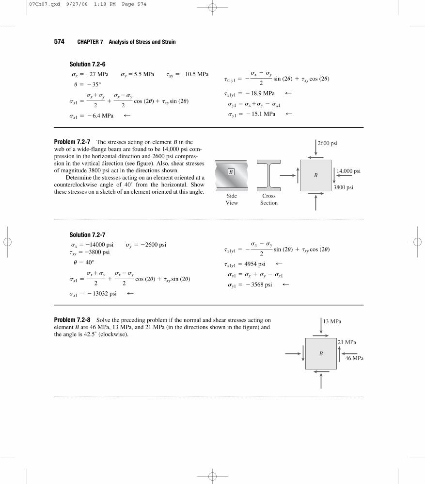
Problem 7.2-6 An element in plane stress from the fuselage of an airplane is subjected to compressive stresses of magnitude 27 MPa in the horizontal direction and tensilestresses of magnitude 5.5 MPa in the vertical direction (see figure). Also, shear stressesof magnitude 10.5 MPa act in the directions shown.
Determine the stresses acting on an element oriented at a clockwise angle of 35˚from the horizontal. Show these stresses on a sketch of an element oriented at thisangle. 10.5 MPa
5.5 MPa
27 MPa
07Ch07.qxd 9/27/08 1:18 PM Page 573
574 CHAPTER 7 Analysis of Stress and Strain
Problem 7.2-7 The stresses acting on element B in the web of a wide-flange beam are found to be 14,000 psi com-pression in the horizontal direction and 2600 psi compres-sion in the vertical direction (see figure). Also, shear stressesof magnitude 3800 psi act in the directions shown.
Determine the stresses acting on an element oriented at acounterclockwise angle of 40˚ from the horizontal. Showthese stresses on a sketch of an element oriented at this angle.
Solution 7.2-6
sx1 � �6.4 MPa ;
sx1 �sx + sy
2+
sx � sy
2 cos (2u) + txy sin (2u)
u � �35°
sx � �27 MPa sy � 5.5 MPa txy � �10.5 MPa
sy1 � �15.1 MPa ;sy1 � sx�sy � sx1
tx1y1 � �18.9 MPa ;
tx1y1 � �sx � sy
2 sin (2u) + txy cos (2u)
B
3800 psi
2600 psi
14,000 psi
SideView
CrossSection
B
Solution 7.2-7
sx1 � �13032 psi ;
sx1 �sx + sy
2+
sx � sy
2 cos (2u) + txy sin (2u)
u � 40°
txy � �3800 psi sx � �14000 psi sy � �2600 psi
sy1 � �3568 psi ; sy1 � sx + sy � sx1
tx1y1 � 4954 psi ;
tx1y1 � �sx � sy
2 sin (2u) + txy cos (2u)
Problem 7.2-8 Solve the preceding problem if the normal and shear stresses acting on element B are 46 MPa, 13 MPa, and 21 MPa (in the directions shown in the figure) andthe angle is 42.5˚ (clockwise).
B46 MPa
13 MPa
21 MPa
07Ch07.qxd 9/27/08 1:18 PM Page 574

SECTION 7.2 Plane Stress 575
Problem 7.2-9 The polyethylene liner of a settling pond is subjected to stresses and , as shown by the plane-stresselement in the first part of the figure.
Determine the normal and shear stresses acting on aseam oriented at an angle of to the element, asshown in the second part of the figure. Show thesestresses on a sketch of an element having its sidesparallel and perpendicular to the seam.
30°
txy � �120 psisx � 350 psi, sy �112 psi,
Solution 7.2-8
sx1 � �51.9 MPa ;
sx1 �sx + sy
2+
sx � sy
2 cos (2u) + txy sin (2u)
u � �42.5°
sx � �46 MPa sy � �13 MPa txy � 21 MPa
sy1 � �7.1 MPa ; sy1 � sx + sy � sx1
tx1y1 � �14.6 MPa ;
tx1y1 � �sx � sy
2 sin (2u) + txy cos (2u)
y
xO
120 psi
112 psi
350 psi
Seam
30°
Solution 7.2-9 Plane stress (angle � )
sy1� sx + sy � sx1
� 275 psi ;� �163 psi ;
tx1y1� �
sx � sy
2 sin 2u + txy cos 2u
� 187 psi ;
sx1�
sx + sy
2+
sx � sy
2 cos 2u + txy sin 2u
u � 30°
sx � 350 psi sy �112 psi txy � �120 psi The normal stress on the seam equals tension.
The shear stress on the seam equals , actingclockwise against the seam. ;
163 psi
;187 psi
07Ch07.qxd 9/27/08 1:18 PM Page 575

576 CHAPTER 7 Analysis of Stress and Strain
Problem 7.2-10 Solve the preceding problem if the normaland shear stresses acting on the element are
, and , and the seam is orientedat an angle of to the element (see figure).22.5°
txy � �560 kPasy � 300 kPasx � 2100 kPa,
y
xO
560 kPa
300 kPa
2100 kPa
Seam
22.5°
Solution 7.2-10 Plane stress (angle � )
u � 22.5°
sx � 2100 kPa sy � 300 kPa txy ��560 kPaThe normal stress on the seam equals tension.The shear stress on the seam equals , actingclockwise against the seam. ;
1030 kPa ;
1440 kPa
sy1� sx + sy � sx1
� 960 kPa ;� �1030 kPa ;
tx1y1� �
sx � sy
2 sin 2u + txy cos 2u
� 1440 kPa ;
sx1�
sx + sy
2+
sx�sy
2 cos 2u + txy sin 2u
Problem 7.2-11 A rectangular plate of dimensions is formed by welding two triangular plates (see figure). The plate is subjected to a tensilestress of in the long direction and a compressive stress of in theshort direction.
Determine the normal stress acting perpendicular to the line of the weldand the shear acting parallel to the weld. (Assume that the normal stress is positive when it acts in tension against the weld and the shear stress ispositive when it acts counterclockwise against the weld.)
tw
swtw
sw
350 psi500 psi
3.0 in. * 5.0 in. 350 psi
Weld500 psi3 in.
5 in.
07Ch07.qxd 9/27/08 1:18 PM Page 576

SECTION 7.2 Plane Stress 577
Problem 7.2-12 Solve the preceding problem for a plate of dimensions subjected to a compressive stress of in the
long direction and a tensile stress of 12.0 MPa in the short direction (see figure).
2.5 MPa100 mm * 250 mm
Solution 7.2-11 Biaxial stress (welded joint)
� 275 psi
sx1�
sx + sy
2+
sx � sy
2 cos 2u + txy sin 2u
u � arctan 3 in.
5 in.� arctan 0.6 � 30.96°
sx � 500 psi sy � �350 psi txy � 0
STRESSES ACTING ON THE WELD
sy1� sx + sy � sx1
� �125 psi
tx1y1� �
sx � sy
2 sin 2u + txy cos 2u � �375 psi
tw � 375 psi ;sw � �125 psi ;
12.0 MPa
Weld 2.5 MPa100 mm250 mm
Solution 7.2-12 Biaxial stress (welded joint)
� �0.5 MPa
sx1�
sx + sy
2+
sx � sy
2 cos 2u + txy sin 2u
u � arctan 100 mm
250 mm� arctan 0.4 � 21.80°
sx � �2.5 MPa sy � 12.0 MPa txy � 0
STRESSES ACTING ON THE WELD
sy1� sx + sy � sx1
� 10.0 MPa
tx1y1� �
sx � sy
2 sin 2u + txy cos 2u � 5.0 MPa
tw � �5.0 MPa ;sw � 10.0 MPa ;
07Ch07.qxd 9/27/08 1:18 PM Page 577

578 CHAPTER 7 Analysis of Stress and Strain
Problem 7.2-13 At a point on the surface of a machine the materialis in biaxial stress with , and asshown in the first part of the figure. The second part of the figureshows an inclined plane cut through the same point in the materialbut oriented at an angle .
Determine the value of the angle between zero and suchthat no normal stress acts on plane . Sketch a stress elementhaving plane as one of its sides and show all stresses acting onthe element.
aaaa
90°u
u
aa
sy � �1600 psi,sx � 3600 psiy
x
a
a
O
1600 psi
3600 psiu
Solution 7.2-13 Biaxial stress
Find angle for .
� normal stress on plane a-a
For , we obtain
‹ 2u �112.62° and u � 56.31°
cos 2u � �1000
2600sx1
� 0
� 1000 + 2600 cos 2u(psi)
sx1�
sx + sy
2+
sx � sy
2 cos 2u + txy sin 2u
s
s � 0u
txy � 0
sy � �1600 psi
sx � 3600 psi
STRESS ELEMENT
� �2400 psi tx1y1
� �sx � sy
2 sin 2u + txy cos 2u
sy1� sx + sy � sx1
� 2000 psi ;sx1
� 0 u � 56.31°
Problem 7.2-14 Solve the preceding problem for and (see figure).sy � �50 MPa
sx � 32 MPa y
x
a
a
O
50 MPa
32 MPau
07Ch07.qxd 9/27/08 1:18 PM Page 578

SECTION 7.2 Plane Stress 579
Problem 7.2-15 An element in plane stress from the frame of a racing car is oriented at a known angle u (see figure). On this inclined element, the normal andshear stresses have the magnitudes and directions shown in the figure.
Determine the normal and shear stresses acting on an element whose sides are parallel to the xy axes, that is, determine sx, sy, and txy. Show the results on a sketch of an element oriented at u � 0˚.
Solution 7.2-14 Biaxial stress
Find angles for .
� normal stress on plane a-a
For , we obtain
‹ 2u � 77.32° and u � 38.66° ;
cos 2u �9
41sx1
� 0
� �9 + 41 cos 2u ( MPa)
sx1�
sx + sy
2+
sx � sy
2 cos 2u + txy sin 2u
s
s � 0u
txy � 0
sy � �50 MPa
sx � 32 MPa
STRESS ELEMENT
� �40 MPa ;
tx1y1� �
sx � sy
2 sin 2u + txy cos 2u
sy1� sx + sy � sx1
� �18 MPa ;sx1
� 0 u � 38.66°
2475 psi3950 psi
14,900 psi
y
xO
u = 40°
Solution 7.2-15
Transform from
sx1 � �12813 psi ;
sx1 �sx + sy
2+
sx � sy
2 cos (2u) + txy sin (2u)
u � �40°
txy � 2475 psisx � �14900 psi sy � �3950 psi
u � 40° to u � 0°
sy1 � �6037 psi ;sy1 � sx + sy � sx1
tx1y1 � �4962 psi ;
tx1y1 � �sx � sy
2 sin (2u) + txy cos (2u)
07Ch07.qxd 9/27/08 1:18 PM Page 579

580 CHAPTER 7 Analysis of Stress and Strain
Problem 7.2-16 Solve the preceding problem for the element shown in thefigure. 24.3 MPa
62.5 MPa
24.0 MPa
y
xO
u = 55°
Solution 7.2-16
Transform from
sx1 � 56.5 MPa ;
sx1 �sx + sy
2+
sx � sy
2 cos (2u) + txy sin (2u)
u � �55°
txy � �24 MPasx � �24.3 MPa sy � 62.5 MPa
u � 55° to u � 0°
sy1 � �18.3 MPa ;sy1 � sx + sy � sx1
tx1y1 � �32.6 MPa ;
tx1y1 � �sx � sy
2 sin (2u) + txy cos (2u)
Problem 7.2-17 A plate in plane stress is subjected to normal stresses sx and sy and shear stress txy, as shown in the figure. At counterclockwise angles u � 35˚ and u � 75˚ from the x axis, the normal stress is 4800 psi tension.
If the stress sx equals 2200 psi tension, what are the stresses sy and txy?
y
xO
txy
sy
sx = 2200 psi
Solution 7.2-17
Find and
sx1 �sx + sy
2+
sx � sy
2 cos (2u) + txy sin (2u)
txysy
At u �35° and u � 75°, sx1 � 4800 psi
sx � 2200 psi sy unknown txy unknown For
(1)or 0.32899 sy + 0.93969 txy � 3323.8 psi
* cos (70°) + txy sin(70°)
4800 psi �2200 psi + sy
2+
2200 psi � sy
2
sx1 � 4800 psi
u � 35°
07Ch07.qxd 9/27/08 1:18 PM Page 580

SECTION 7.2 Plane Stress 581
For
* cos (150°) + txy sin(150°)
4800 psi �2200 psi + sy
2+
2200 psi � sy
2
sx1 � 4800 psi
u � 75°: (2)
Solve Eqs. (1) and (2):
sy � 3805 psi txy � 2205 psi ;
or 0.93301sy + 0.50000 txy � 4652.6 psi
Problem 7.2-18 The surface of an airplane wing is subjected to plane stresswith normal stresses sx and sy and shear stress txy, as shown in the figure. At acounterclockwise angle u � 32˚ from the x axis, the normal stress is 37 MPatension, and at an angle u � 48˚, it is 12 MPa compression.
If the stress sx equals 110 MPa tension, what are the stresses sy and txy?
y
xO
txy
sy
sx = 110 MPa
Solution 7.2-18
Find and
For
* cos (64°) + txy sin (64°)
37 MPa �110 MPa + sy
2+
110 MPa � sy
2
sx1 � 37 MPa
u � 32°
sx1 �sx + sy
2+
sx �sy
2 cos(2u) + txy sin(2u)
txysy
At u � 48°, sx1 � �12 MPa (compression)
At u � 32°, sx1 � 37 MPa (tension)
sx � 110 MPa sy unknown sxy unknown (1)
For
(2)
Solve Eqs. (1) and (2):
sy � �60.7 MPa txy � �27.9 MPa ;
or 0.55226sy + 0.99452txy � �61.25093 MPa
* cos (96°) + txy sin (96°)
�12 MPa �110 MPa + sy
2+
110 MPa � sy
2
sx1 � �12 MPa
u � 48°:
or 0.28081sy + 0.89879txy � �42.11041 MPa
07Ch07.qxd 9/27/08 1:18 PM Page 581

582 CHAPTER 7 Analysis of Stress and Strain
Problem 7.2-19 At a point in a structure subjected to plane stress, the stresses are sx � �4100 psi, sy � 2200 psi, and txy � 2900 psi (the sign convention for thesestresses is shown in Fig. 7-1). A stress element located at the same point in the structure(but oriented at a counterclockwise angle u1 with respect to the x axis) is subjected tothe stresses shown in the figure (sb, tb, and 1800 psi).
Assuming that the angle u1 is between zero and 90˚, calculate the normal stress sb, theshear stress tb, and the angle u1
1800 psi
O x
y
tbsb
u1
Solution 7.2-19
For
Find
Stress
Angle
sx1 �sx + sy
2+
sx � sy
2 cos (2u) + txy sin (2u)
u1
sb � sx + sy �1800 psi sb � �3700 psi ;sb
sb, tb, and u1
sx1 � 1800 psi sy1 � sb tx1y1 � tb
u � u1:
txy � 2900 psisx � �4100 psi sy � 2200 psi
SOLVE NUMERICALLY:
Shear Stress
tb � 3282 psi ;
tb � �sx � sy
2 sin 12u12 + txy cos 12u12
tb
2u1 � 87.32° u1 � 43.7° ;
+ 2900 psi sin 12u121800 psi � �950 psi � 3150 psi cos12u12
Principal Stresses and Maximum Shear Stresses
When solving the problems for Section 7.3, consider only the in-plane stresses (the stresses in the xy plane).
Problem 7.3-1 An element in plane stress is subjected to stresses sx � 4750 psi, sy � 1200 psi, and txy � 950 psi (see thefigure for Problem 7.2-1).
Determine the principal stresses and show them on a sketch of a properly oriented element.
Solution 7.3-1
PRINCIPAL STRESSES
up1 � 14.08°
up1 �
atana 2 txy
sx � syb
2
sx � 4750 psi sy � 1200 psi txy � 950 psi
s2 � 962 psi ;s1 � 4988 psi ;
s2 �sx + sy
2+
sx � sy
2 cos 12up22 + txy sin 12up22
s1 �sx + sy
2+
sx � sy
2 cos 12up12 + txy sin 12up12
up2 � up1 + 90° up2 � 104.08°
07Ch07.qxd 9/27/08 1:18 PM Page 582

SECTION 7.3 Principal Stresses and Maximum Shear Stresses 583
Problem 7.3-2 An element in plane stress is subjected to stresses sx � 100 MPa, sy � 80 MPa, and txy � 28 MPa (see thefigure for Problem 7.2-2).
Determine the principal stresses and show them on a sketch of a properly oriented element.
Solution 7.3-2
PRINCIPAL STRESSES
up2 � up1 + 90° up2 � 125.17°
up1 � 35.2°
up1 �
atana 2 txy
sx � syb
2
sx � 100 MPa sy � 80 MPa txy � 28 MPa
s2 � 60 MPa ;s1 � 120 MPa ;
s2 �sx + sy
2+
sx � sy
2 cos12up22 + txy sin12up22
s1 �sx + sy
2+
sx � sy
2 cos12up12 + txy sin12up12
Problem 7.3-3 An element in plane stress is subjected to stresses sx � �5700 psi, sy � �2300 psi, and txy � 2500 psi(see the figure for Problem 7.2-3).
Determine the principal stresses and show them on a sketch of a properly oriented element.
Solution 7.3-3
PRINCIPAL STRESSES
up1 � up2 + 90° up1 � 62.1°
up2 � �27.89°
up2 �
atana 2txy
sx � syb
2
sx � �5700 psi sy � �2300 psi txy � 2500 psi
s2 � �7023 psi ;s1 � �977 psi ;
s2 �sx + sy
2+
sx � sy
2 cos12up22 + txy sin12up22
s1 �sx + sy
2+
sx � sy
2 cos12up12 + txy sin12up12
Problem 7.3-4 The stresses acting on element A in the web of a train rail are found to be 40 MPa tension in the horizontaldirection and 160 MPa compression in the vertical direction (see figure). Also, shear stresses of magnitude 54 MPa act in thedirections shown (see the figure for Problem 7.2-4).
Determine the principal stresses and show them on a sketch of a properly oriented element.
07Ch07.qxd 9/27/08 1:18 PM Page 583

584 CHAPTER 7 Analysis of Stress and Strain
Problem 7.3-5 The normal and shear stresses acting on element A are 6500 psi, 18,500 psi, and 3800 psi (in the directionsshown in the figure) (see the figure for Problem 7.2-5).
Determine the maximum shear stresses and associated normal stresses and show them on a sketch of a properly orientedelement.
Solution 7.3-4
PRINCIPAL STRESSES
up2 � up1 + 90° up2 � 75.8°
up1 � �14.2°
up1 �
atana 2txy
sx � syb
2
sx � 40 MPa sy � �160 MPa txy � �54 MPa
s2 � �173.6 MPa ;s1 � 53.6 MPa ;
s2 �sx + sy
2+
sx � sy
2 cos 12up22 + txy sin 12up22
s1 �sx + sy
2+
sx � sy
2 cos 12up1
2 + txy sin 12up12
Solution 7.3-5
PRINCIPAL ANGLES
s2 �sx + sy
2+
sx � sy
2 cos 12up22 + txy sin 12up22
s1 �sx + sy
2+
sx � sy
2 cos 12up1
2 + txy sin 12up12
up2 � up1 + 90° up2 � 81.55°
up1 � �8.45°
up1 �
atana 2txy
sx � syb
2
sx � 6500 psi sy � �18500 psi txy � �3800 psi
MAXIMUM SHEAR STRESSES
saver �sx + sy
2 saver � �6000 psi ;
us1 � up1 � 45° us1 � �53.4° ;
tmax � Aasx � sy
2b2
+ txy2 tmax � 13065 psi ;
s2 � �19065 psi
s1 � 7065 psi
Problem 7.3-6 An element in plane stress from the fuselage of an airplane is subjected to compressive stresses of magnitude 27 MPa in the horizontal direction and tensile stresses of magnitude 5.5 MPa in the vertical direction. Also, shear stresses of magnitude 10.5 MPa act in the directions shown (see the figure for Problem 7.2-6).
Determine the maximum shear stresses and associated normal stresses and show them on a sketch of a properly orientedelement.
07Ch07.qxd 9/27/08 1:18 PM Page 584

SECTION 7.3 Principal Stresses and Maximum Shear Stresses 585
Problem 7.3-7 The stresses acting on element B in the web of a wide-flange beam are found to be 14,000 psi compressionin the horizontal direction and 2600 psi compression in the vertical direction. Also, shear stresses of magnitude 3800 psi actin the directions shown (see the figure for Problem 7.2-7).
Determine the maximum shear stresses and associated normal stresses and show them on a sketch of a properly orientedelement.
Solution 7.3-6
PRINCIPAL ANGLES
s2 �sx + sy
2+
sx � sy
2 cos 12up22 + txy sin 12up22
s1 �sx + sy
2+
sx � sy
2 cos 12up1
2 + txy sin 12up12
up1 � up2 + 90° up1 � 106.43°
up2 � 16.43°
up2 �
atana 2txy
sx � syb
2
sx � �27 MPa sy � 5.5 MPa txy � �10.5 MPa
MAXIMUM SHEAR STRESSES
saver �sx + sy
2 saver � �10.8 MPa ;
us1 � up1 � 45° us1 � 61.4°
tmax � 19.3 MPa ;
tmax � A asx � sy
2b2
+ txy2
s2 � �30.1 MPa
s1 � 8.6 MPa
Solution 7.3-7
PRINCIPAL ANGLES
s1 �sx + sy
2+
sx � sy
2 cos12up1
2 + txy sin12up12
up1 � up2 + 90° up1 � 106.85°
up2 � 16.85°
up2 �
atana 2txy
sx � syb
2
txy � �3800 psisx � �14000 psi sy � �2600 psi
MAXIMUM SHEAR STRESSES
saver �sx + sy
2 saver � �8300 psi ;
us1 � up1 � 45° us1 � 61.8° ;
tmax � A asx � sy
2b2
+ txy2 tmax � 6851 psi ;
s2 � �15151 psi
s1 � �1449 psi
s2 �sx + sy
2+
sx � sy
2 cos12up22 + txy sin12up22
Problem 7.3-8 The normal and shear stresses acting on element B are sx � �46 MPa, sy � �13 MPa, and txy � 21 MPa(see figure for Problem 7.2-8).
Determine the maximum shear stresses and associated normal stresses and show them on a sketch of a properly orientedelement.
07Ch07.qxd 9/27/08 1:18 PM Page 585

586 CHAPTER 7 Analysis of Stress and Strain
Problem 7.3-9 A shear wall in a reinforced concrete building is subjected to a vertical uniform load of intensity q and a horizontalforce H, as shown in the first part of the figure. (The force Hrepresents the effects of wind and earthquake loads.) As aconsequence of these loads, the stresses at point A on the surfaceof the wall have the values shown in the second part of the figure (compressive stress equal to 1100 psi and shear stress equal to 480 psi).
(a) Determine the principal stresses and show them on a sketchof a properly oriented element.
(b) Determine the maximum shear stresses and associatednormal stresses and show them on a sketch of a properly oriented element.
Solution 7.3-8
PRINCIPAL ANGLES
s2 �sx + sy
2+
sx � sy
2 cos 12up22 + txy sin 12up22
s1 �sx + sy
2+
sx � sy
2 cos 12up1
2 + txy sin 12up12
up1 � up2 + 90° up1 � 64.08°
up2 � �25.92°
up2 �
atana 2txy
sx � syb
2
sx � �46 MPa sy � �13 MPa txy � 21 MPa
MAXIMUM SHEAR STRESSES
saver �sx � sy
2 saver � �29.5 MPa ;
us1 � up1 � 45° us1 � 19.08° ;
tmax � Aasx � sy
2b2
+ txy2 tmax � 26.7 MPa ;
s2 � �56.2 MPa
s1 � �2.8 MPa
1100 psi
480 psi
A
A
q
H
Solution 7.3-9 Shear wall
(a) PRINCIPAL STRESSES
For
For sx1� �1280 psi2up � 138.89°:
2up � �41.11°: sx1� 180 psi
sx1�
sx + sy
2+
sx � sy
2 cos 2u + txy sin 2u
2up � 138.89° and up � 69.44°
2up � �41.11° and up � �20.56°
tan 2up �2txy
sx � sy� �0.87273
sx � 0 sy � �1100 psi txy � �480 psi
s2 � �1280 psi and up2� 69.44°
Therefore, s1 �180 psi and up1� �20.56° f ;
07Ch07.qxd 9/27/08 1:18 PM Page 586

SECTION 7.3 Principal Stresses and Maximum Shear Stresses 587
(b) MAXIMUM SHEAR STRESSES
and
saver �sx + sy
2� �550 psi ;
t � �730 psius2� up1
+ 45° � 24.44°
us1� up1
� 45° � �65.56° and t � 730 psi
tmax � A asx � sy
2b2 + t2
xy � 730 psi
f ;
Problem 7.3-10 A propeller shaft subjected to combined torsion and axial thrust is designed to resist a shear stress of 56 MPa and a compressive stress of 85 MPa(see figure).
(a) Determine the principal stresses and show them on a sketch of a properlyoriented element.
(b) Determine the maximum shear stresses and associated normal stressesand show them on a sketch of a properly oriented element.
85 MPa
56 MPa
Solution 7.3-10
(a) PRINCIPAL STRESSES
s2 �sx + sy
2+
sx � sy
2 cos 12up22 + txy sin 12up22
s1 �sx + sy
2+
sx � sy
2 cos 12up1
2 + txy sin 12up12
up1 � up2 + 90° up1 � 116.4° ;up2 � 26.4°
up2 �
atana 2txy
sx � syb
2
sx � �85 MPa sy � 0 MPa Txy � �56 MPa
(b) MAXIMUM SHEAR STRESSES
saver �sx + sy
2 saver � �42.5 MPa ;
us1 � up1 � 45° us1 � 71.4° ;tmax � 70.3 MPa ;
tmax � A asx � sy
2b2 + txy
2
;s2 � �112.8 MPa
;s1 � 27.8 MPa
07Ch07.qxd 9/27/08 1:18 PM Page 587

588 CHAPTER 7 Analysis of Stress and Strain
Problems 7.3-11 sx � 2500 psi, sy � 1020 psi, txy � �900 psi
(a) Determine the principal stresses and show them on a sketch of a properlyoriented element.
(b) Determine the maximum shear stresses and associated normal stresses andshow them on a sketch of a properly oriented element.
y
xO
txy
sx
sy
Solution 7.3-11
(a) PRINCIPAL STRESSES
s2 �sx + sy
2+
sx � sy
2 cos 12up22 + txy sin 12up22
s1 �sx + sy
2+
sx � sy
2 cos 12up1
2 + txy sin 12up12
up2 � 90 ° + up1 up2 � 64.71°
up1 � 25.29°
tan(2up) �2txy
sx � sy up1 �
atana 2txy
sx � syb
2
sx � 2500 psi sy � 1020 psi txy � �900 psi Therefore,
(b) MAXIMUM SHEAR STRESSES
saver �sx + sy
2 saver � 1760 psi ;
t2 � �1165 psi ;us2 � up1 � 45° us2 � 19.71° and
t1 � 1165 psi ;us1 � up1 � 45° us1 � �70.3° and
tmax � 1165 psi
tmax � A asx � sy
2b2
+ txy2
s2 � 595 psi ;For up2 � 64.7°:
For up1 � �25.3°: s1 � 2925 psi ;
Problems 7.3-12 sx � 2150 kPa, sy � 375 kPa, txy � �460 kPa
(a) Determine the principal stresses and show them on a sketch of a properly oriented element. (b) Determine the maximum shear stresses and associated normal stresses and show them on a sketch of a properly
oriented element.
Solution 7.3-12
(a) PRINCIPAL STRESSES
tan(2up) �2txy
sx � sy up1 �
atana 2txy
sx�syb
2
sx � 2150 kPa sy � 375 kPa txy � �460 kPa
s2 �sx + sy
2+
sx � sy
2 cos 12up22 + txy sin 12up22
s1 �sx + sy
2+
sx � sy
2 cos 12up1
2 + txy sin 12up12
up2 � 90° + up1 up2 � 76.30°
up1 � �13.70°
Probs. 7.3-11 through 7.3-16
07Ch07.qxd 9/27/08 1:18 PM Page 588

SECTION 7.3 Principal Stresses and Maximum Shear Stresses 589
Therefore,
(b) MAXIMUM SHEAR STRESSES
tmax � A asx � sy
2b2
+ txy2
;s2 � 263 kPaFor up2 � 76.3°
;For up1 � �13.70° s1 � 2262 kPa
saver �sx + sy
2 saver � 1263 kPa
and t2 ��1000 kPa;us2 � up1 + 45° us2 � 31.3°
and t1 � 1000 kPa;us1 � up1 � 45° us1 � �58.7°
tmax � 145 psi
Problems 7.3-13 sx � 14,500 psi, sy � 1070 psi, txy � 1900 psi
(a) Determine the principal stresses and show them on a sketch of a properly oriented element. (b) Determine the maximum shear stresses and associated normal stresses and show them on a sketch of a properly
oriented element.
Solution 7.3-13
(a) PRINCIPAL STRESSES
s2 �sx + sy
2+
sx � sy
2 cos 12up22 + txy sin 12up22
s1 �sx + sy
2+
sx � sy
2 cos 12up1
2 + txy sin 12up12
up2 � 90° + up1 up2 � 97.90°
up1 � 7.90°
tan(2up) �2txy
sx � sy up1 �
atana 2txy
sx�syb
2
sx � 14500 psi sy � 1070 psi txy � 1900 psi Therefore,
(b) MAXIMUM SHEAR STRESSES
saver �sx + sy
2 saver � 7785 psi
and t2 ��6979 psi;us2 � up1 + 45° us2 � 52.9°
and t1 � 6979 psi;us1 � up1 � 45° us1 � �37.1°
tmax � 6979 psi
tmax � A asx � sy
2b2
+ txy2
;For up2 � 97.9° s2 � 806 psi
;For up1 � 7.90° s1 � 14764 psi
Problems 7.3-14 sx � 16.5 MPa, sv � �91 MPa, txy � �39 MPa
(a) Determine the principal stresses and show them on a sketch of a properly oriented element. (b) Determine the maximum shear stresses and associated normal stresses and show them on a sketch of a properly
oriented element.
07Ch07.qxd 9/27/08 1:18 PM Page 589

590 CHAPTER 7 Analysis of Stress and Strain
Solution 7.3-14
(a) PRINCIPAL STRESSES
Therefore,
For
For s2 � �103.7 MPaup2 � 72.0°
up1 � �17.98° s1 � 29.2 MPa
s2 �sx + sy
2+
sx � sy
2 cos 12up22 + txy sin 12up22
s1 �sx + sy
2+
sx � sy
2 cos 12up1
2 + txy sin 12up12
up2 � 90° + up1 up2 �72.02°
up1 � �17.98°
tan(2up) �2txy
sx � sy up1 �
atana 2txy
sx�syb
2
sx � 16.5 MPa sy � �91 MPa txy � �39 MPa (b) MAXIMUM SHEAR STRESSES
saver �sx + sy
2 saver � �37.3 MPa
and t2 � �66.4 MPa;us2 � up1 + 45° us2 � 27.0°
and t1 � 66.4 MPa;us1 � up1 � 45° us1 � �63.0°
tmax � 9631.7 psi
tmax � A asx � sy
2b2
+ txy2
Problems 7.3-15 sx � �3300 psi, sy � �11,000 psi, txy � 4500 psi
(a) Determine the principal stresses and show them on a sketch of a properly oriented element. (b) Determine the maximum shear stresses and associated normal stresses and show them on a sketch of a properly
oriented element.
Solution 7.3-15
(a) PRINCIPAL STRESSES
s2 �sx + sy
2+
sx � sy
2 cos 12up22 + txy sin 12up22
s1 �sx + sy
2+
sx � sy
2 cos 12up12 + txy sin 12up12
up2 � 90° + up1 up2 � 114.73°
up1 � 24.73°
tan(2up) �2txy
sx � sy up1 �
atana 2txy
sx�syb
2
s � �3300 psi sy ��11000 psi txy � 4500 psi Therefore,For
For
(b) MAXIMUM SHEAR STRESSES
saver �sx + sy
2 saver � �7150 psi
and t2 � �5922 psi;us2 � up1 + 45° us2 � 69.7°
and t1 � 5922 psi;us1 � up1 � 45° us1 � �20.3°
tmax � 5922 psi
tmax � A asx � sy
2b2
+ txy2
up2 � 114.7° s2 � �13072 psi
up1 � 24.7° s1 � �1228 psi
07Ch07.qxd 9/27/08 1:18 PM Page 590

SECTION 7.3 Principal Stresses and Maximum Shear Stresses 591
Problems 7.3-16 sx � �108 MPa, sy � 58 MPa, txy � �58 MPa
(a) Determine the principal stresses and show them on a sketch of a properly oriented element. (b) Determine the maximum shear stresses and associated normal stresses and show them on a sketch of a properly
oriented element.
Solution 7.3-16
(a) PRINCIPAL STRESSES
Therefore,
For
For ;s2 � �126.3 MPaup2 � 17.47°
;up1 � 107.47° s1 � 76.3 MPa
s2 �sx + sy
2+
sx � sy
2 cos 12up22 + txy sin 12up22
s1 �sx + sy
2+
sx � sy
2 cos 12up1
2 + txy sin 12up12
up1 � 90° + up2 up1 � 107.47°
up2 � 17.47°
tan(2up) �2txy
sx � sy up2 �
atana 2txy
sx�syb
2
sx � �108 MPa sy � 58 MPa txy � �58 MPa (b) MAXIMUM SHEAR STRESSES
saver �sx + sy
2 saver � �25.0 MPa
and t2 ��101.3 MPa;us2 � up1 + 45° us2 � 152.47°
and t1 � 101.3 MPa;us1 � up1 � 45° us1 � 62.47°
tmax � 14686.1 psi
tmax � A asx � sy
2b2
+ txy2
Problem 7.3-17 At a point on the surface of a machine component, the stresses acting on the x face of a stress element are sx � 5900 psi and txy � 1950 psi(see figure).
What is the allowable range of values for the stress sy if the maximum shear stressis limited to t0 � 2500 psi?
y
xO
txy = 1950 psi
sy
sx = 5900 psi
07Ch07.qxd 9/27/08 1:18 PM Page 591

592 CHAPTER 7 Analysis of Stress and Strain
Problem 7.3-18 At a point on the surface of a machine component the stresses acting on the x face of a stress element are sx � 42 MPa and txy � 33 MPa (see figure).
What is the allowable range of values for the stress sy if the maximum shearstress is limited to t0 � 35 MPa?
Solution 7.3-17
Find the allowable range of values for if the
maximum allowable shear stresses is
(1)
Solve for
sy � a9029
2771b psisy � sx� J
22tmax2�txy
2
� a22tmax2 �txy
2b Ksy
tmax � A asx � sy
2b2
+ txy2
tmax � 2500 psi
sy
sx � 5900 psi sy unknown txy � 1950 psi Therefore,
From Eq. (1):
tmax(sy1) � A asx � sy1
2b2
+ txy2
2771 psi … sy … 9029 psi
2.5 ksi
tmax(σy1)
σy1
2.771 ksi 9.029 ksi
y
xO
txy = 33 MPa
sy
sx = 42 MPa
Solution 7.3-18
Find the allowable range of values for if themaximum allowable shear stresses is tmax � 35 MPa
sy
sx � 42 MPa sy unknown txy � 33 MPa(1)tmax � A a
sx � sy
2b2
+ txy2
07Ch07.qxd 9/27/08 1:18 PM Page 592

SECTION 7.3 Principal Stresses and Maximum Shear Stresses 593
35 MPa
18.7 MPa 65.3 MPa
tmax (σy1)
σy1
Problem 7.3-19 An element in plane stress is subjected to stresses sx � 5700 psi and txy � �2300 psi (see figure). It is known that one of the principal stresses equals6700 psi in tension.
(a) Determine the stress sy.(b) Determine the other principal stress and the orientation of the principal planes,
then show the principal stresses on a sketch of a properly oriented element.
y
xO5700 psi
sy
2300 psi
Solve for
Therefore, 18.7 MPa … sy … 65.3 MPa
sy � a65.3
18.7b MPasy � sx� J
22tmax2�txy
2
� a22tmax2 �txy
2b Ksy From Eq. (1):
tmax(sy1) � A asx � sy1
2b2
+ txy2
Solution 7.3-19
(a) STRESS
Because is smaller than a given principal stress,we know that the given stress is the larger principalstress.
s1 �sx + sy
2+ A a
sx � sy
2b2
+ txy2
s1 � 6700 psi
sy
sy
sx � 5700 psi sy unknown txy � �2300 psi Solve for
(b) PRINCIPAL STRESSES
up2 � 90° + up1 up2 � 66.50°
up1 � �23.50°
tan (2up) �2txy
sx � sy up1 �
atana 2txy
sx �syb
2
sy sy � 1410 psi ;
07Ch07.qxd 9/27/08 1:18 PM Page 593

594 CHAPTER 7 Analysis of Stress and Strain
Problem 7.3-20 An element in plane stress is subjected to stresses sx � �50 MPa and txy � 42 MPa (see figure). It is known that one of the principal stresses equals33 MPa in tension.
(a) Determine the stress sy.(b) Determine the other principal stress and the orientation of the principal planes,
then show the principal stresses on a sketch of a properly oriented element.
y
xO
42 MPa
sy
50 MPa
Solution 7.3-20
(a) STRESS
Because is smaller than a given principal stress,we know that the given stress is the larger principalstress.
Solve for
(b) PRINCIPAL STRESSES
tan(2up) �2txy
sx � sy up2 �
atana 2txy
sx �syb
2
sy sy � 11.7 MPa ;
s1 �sx + sy
2+ A a
sx � sy
2b2
+ txy2
s1 � 33 MPa
sy
sy
sx � �50 MPa sy unknown txy � 42 MPa
Therefore,
For
For up2 � �26.8° : s2 � �71.3 MPa ;up1 � 63.2° : s1 � 33.0 MPa ;
+ txy sin 12up22s2 �
sx + sy
2+
sx � sy
2 cos 12up22
+ txy sin 12up12
s1 �sx + sy
2+
sx � sy
2 cos 12up1
2up1 � 90° + up2 up1 � 63.15°
up2 � �26.85°
+ txy sin 12up22s2 �
sx + sy
2+
sx � sy
2 cos 12up22
+ txy sin12up12
s1 �sx + sy
2+
sx � sy
2 cos 12up1
2 Therefore,
For
For up2 � 66.5° : s2 � 410 psi ;up1 � �23.5° : s1 � 6700 psi ;
07Ch07.qxd 9/27/08 1:18 PM Page 594

SECTION 7.4 Mohr’s Circle 595
Mohr’s CircleThe problems for Section 7.4 are to be solved using Mohr’s circle. Consider only thein-plane stresses (the stresses in the xy plane).
Problem 7.4-1 An element in uniaxial stress is subjected to tensile stresses sx � 11,375 psi, as shown in the figure. Using Mohr’s circle, determine:
(a) The stresses acting on an element oriented at a counterclockwise angle u � 24°from the x axis.
(b) The maximum shear stresses and associated normal stresses.Show all results on sketches of properly oriented elements.
y
xO11,375 psi
Solution 7.4-1
(a) ELEMENT AT
PointDœ: sy1 � R � R cos (2u)
tx1y1 � �4227 psi ;tx1y1 � �R sin (2u)
sx1 � 9493 psi ;Point D: sx1 � R + R cos(2u)
Point C: sc � R sc � 5688 psi
2u � 48° R �sx
2 R � 5688 psi
; u � 24°
sx � 11375 psi sy � 0 psi txy � 0 psi
(b) MAXIMUM SHEAR STRESSES
saver � R saver � 5688 psi ;tmax � �R tmax � �5688 psi ;
Point S2: us2 �90°
2 us2 � 45° ;
tmax � R tmax � 5688 psi ;
Point S1: us1 ��90°
2 us1 ��45° ;
sy1 � 1882 psi ;
Problem 7.4-2 An element in uniaxial stress is subjected to tensile stresses sx � 49 MPa, as shown in the figure Using Mohr’s circle, determine:
(a) The stresses acting on an element oriented at an angle u � �27° from the xaxis (minus means clockwise).
(b) The maximum shear stresses and associated normal stresses.Show all results on sketches of properly oriented elements.
y
xO49 MPa
Solution 7.4-2
(a) ELEMENT AT
Point C: sc � R sc � 24.5 MPa
2u � �54.0° R �sx
2 R � 24.5 MPa
u � �27°
sx � 49 MPa sy � 0 MPa txy � 0 MPa Point D:
Point
sy1 � 10.1 MPa ;D
œ
sy1 � R � R cos ( |2u| )
tx1y1 � 19.8 MPa ;tx1y1 � �R sin (2u)
sx1 � 38.9 MPa ; sx1 � R + R cos (|2u|)
07Ch07.qxd 9/27/08 1:19 PM Page 595

596 CHAPTER 7 Analysis of Stress and Strain
(b) MAXIMUM SHEAR STRESSES
Point S1:
tmax � R tmax � 24.5 MPa ; ;us1 � �45.0°
us1 ��90°
2
Point S2:
saver � R saver � 24.5 MPa ;tmax � �R tmax � �24.5 MPa ;
us2 �90°
2 us2 � 45.0° ;
Problem 7.4-3 An element in uniaxial stress is subjected to compressive stresses of magnitude 6100 psi, as shown in the figure. Using Mohr’s circle, determine:
(a) The stresses acting on an element oriented at a slope of 1 on 2 (see figure).(b) The maximum shear stresses and associated normal stresses.Show all results on sketches of properly oriented elements.
y
xO
6100 psi
12
Solution 7.4-3
(a) ELEMENT AT A SLOPE OF 1 ON 2
Point C:
Point D:
tx1y1 � �R sin (2u) tx1y1 � 2440 psi ;sx1 � �4880 psi ;
sx1 � R + R cos (2u)
sc � R sc � �3050 psi
2u � 53.130° R �sx
2 R � �3050 psi
;u � atana1
2b u � 26.565°
sx � �6100 psi sy � 0 psi txy � 0 psi Point
(b) MAXIMUM SHEAR STRESSES
Point S1:
Point S2:
saver � R saver � �3050 psi ;tmax � R tmax � �3050 psi ;
us2 � �45° ; us2 ��90°
2
tmax � �R tmax � 3050 psi ;
us1 �90°
2 us1 � 45° ;
sy1 � �1220 psi
Dœ
: sy1 � R � R cos (2u)
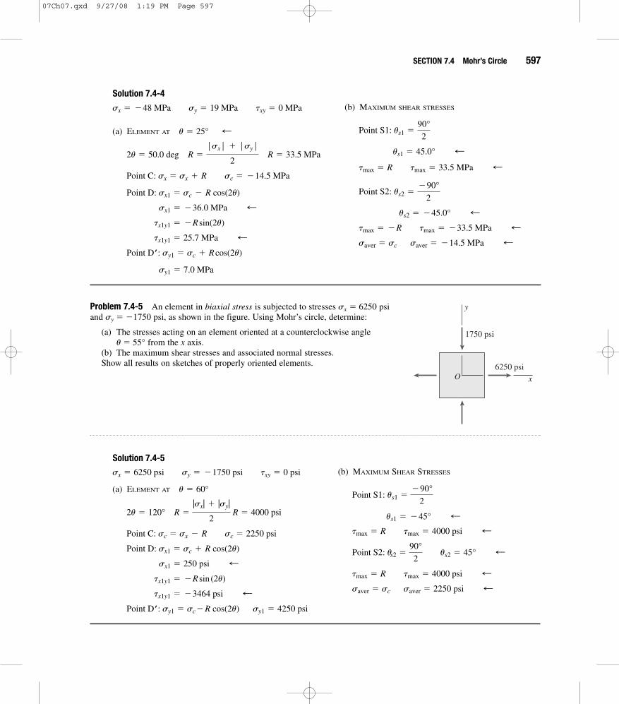
Problem 7.4-4 An element in biaxial stress is subjected to stresses sx � �48 MPa and sy � 19 MPa, as shown in the figure. Using Mohr’s circle, determine:
(a) The stresses acting on an element oriented at a counterclockwise angle u � 25°from the x axis.
(b) The maximum shear stresses and associated normal stresses.
Show all results on sketches of properly oriented elements.
y
xO
19 MPa
48 MPa
07Ch07.qxd 9/27/08 1:19 PM Page 596
SECTION 7.4 Mohr’s Circle 597
Solution 7.4-4
(a) ELEMENT AT
sy1 � 7.0 MPa
Point Dœ: sy1 � sc + R cos(2u)
tx1y1 � 25.7 MPa ;tx1y1 � �R sin(2u)
sx1 � �36.0 MPa ;Point D: sx1 � sc � R cos(2u)
sc � �14.5 MPaPoint C: sx � sx + R
2u � 50.0 deg R �|sx| + |sy|
2 R � 33.5 MPa
; u � 25°
sx � �48 MPa sy � 19 MPa txy � 0 MPa (b) MAXIMUM SHEAR STRESSES
saver � sc saver � �14.5 MPa ;tmax � �R tmax � �33.5 MPa ;
us2 � �45.0° ;
Point S2: us2 ��90°
2
tmax � R tmax � 33.5 MPa ;us1 � 45.0° ;
Point S1: us1 �90°
2
Problem 7.4-5 An element in biaxial stress is subjected to stresses sx � 6250 psi and sy � �1750 psi, as shown in the figure. Using Mohr’s circle, determine:
(a) The stresses acting on an element oriented at a counterclockwise angle u � 55° from the x axis.
(b) The maximum shear stresses and associated normal stresses.Show all results on sketches of properly oriented elements.
y
xO
1750 psi
6250 psi
Solution 7.4-5
(a) ELEMENT AT
sy1 � 4250 psiPoint Dœ: sy1 � sc� R cos(2u)
tx1y1 � �3464 psi ;tx1y1 � �R sin (2u)
sx1 � 250 psi ;Point D: sx1 � sc + R cos(2u)
Point C: sc � sx � R sc � 2250 psi
2u � 120° R �|sx| + |sy|
2 R � 4000 psi
u � 60°
sx � 6250 psi sy � �1750 psi txy � 0 psi (b) MAXIMUM SHEAR STRESSES
saver � sc saver � 2250 psi ;tmax � R tmax � 4000 psi ;
Point S2: us2 �90°
2 us2 � 45° ;
tmax � R tmax � 4000 psi ;us1 � �45° ;
Point S1: us1 ��90°
2
07Ch07.qxd 9/27/08 1:19 PM Page 597

598 CHAPTER 7 Analysis of Stress and Strain
Problem 7.4-6 An element in biaxial stress is subjected to stresses sx � �29 MPa and sy � 57 MPa, as shown in the figure. Using Mohr’s circle, determine:
(a) The stresses acting on an element oriented at a slope of 1 on 2.5 (see figure).(b) The maximum shear stresses and associated normal stresses.Show all results on sketches of properly oriented elements.
y
xO
57 MPa
29 MPa
1
2.5
Solution 7.4-6
(a) ELEMENT AT A SLOPE OF 1 ON 2.5
sy1 � 45.1 MPa
Point Dœ: sy1 � sc + R cos (2u)
;tx1y1 � R sin (2u) tx1y1 � 29.7 MPa
sx1 � �17.1 MPa ;Point D: sx1 � sc � R cos (2u)
Point C: sc � sx + R sc � 14.0 MPa
2u � 43.603° R �|sx| + |sy|
2 R � 43.0 MPa
;u � atana 1
2.5b u � 21.801°
sx � �29 MPa sy � 57 MPa txy � 0 MPa (b) MAXIMUM SHEAR STRESSES
saver � sc saver � 14.0 MPa ;tmax � �R tmax � �43.0 MPa ;
us2 � �45.0° ;
Point S2: us2 ��90°
2
tmax � R tmax � 43.0 MPa ;
Point S1: us1 �90°
2 us1 � 45.0° ;
Problem 7.4-7 An element in pure shear is subjected to stresses txy � 2700 psi, as shown in the figure. Using Mohr’s circle, determine:
(a) The stresses acting on an element oriented at a counterclockwise angle u � 52° fromthe x axis.
(b) The principal stresses.Show all results on sketches of properly oriented elements.
y
xO
2700 psi
07Ch07.qxd 9/27/08 1:19 PM Page 598

SECTION 7.4 Mohr’s Circle 599
Solution 7.4-7
(a) ELEMENT AT
sy1 � �2620 psi ;
Point Dœ: sy1 � �R cos (2u � 90°)
tx1y1 � �653 psi ;tx1y1 � �R sin (2u � 90°)
sx1 � 2620 psi ;Point D: sx1 � R cos (2u � 90°)
2u � 104.0° R � txy R � 2700 psi
u � 52°
sx � 0 psi sy � 0 psi txy � 2700 psi (b) PRINCIPAL STRESSES
s2 � �R s2 � �2700 psi ;
;up2 � �45°
Point P2: up2 ��90°
2
s1 � R s1 � 2700 psi ;
Point P1: up1 �90°
2 up1 � 45° ;
Problem 7.4-8 An element in pure shear is subjected to stresses txy � �14.5 MPa, asshown in the figure. Using Mohr’s circle, determine:
(a) The stresses acting on an element oriented at a counterclockwise angle u � 22.5°from the x axis
(b) The principal stresses.Show all results on sketches of properly oriented elements.
y
xO
14.5 MPa
Solution 7.4-8
(a) ELEMENT AT
sy1 � 10.25 MPa ;
Point Dœ: sy1 � R cos (2u � 90°)
tx1y1 � �10.25 MPa ;tx1y1 � R sin (2u � 90°)
sx1 � �10.25 MPa ;Point D: sx1 � �R cos (2u � 90°)
R � |txy| R � 14.50 MPa
2u � 45.00°
u � 22.5°
sx � 0 MPa sy � 0 MPa txy � �14.5 MPa (b) PRINCIPAL STRESSES
s2 � �14.50 MPa ;
s2 � �R
up2 � �135.0° ;
Point P2: up2 ��270°
2
s1 � R s1 � 14.50 MPa ;
;up1 � 135.0°Point P1: up1 �270°
2
07Ch07.qxd 9/27/08 1:19 PM Page 599
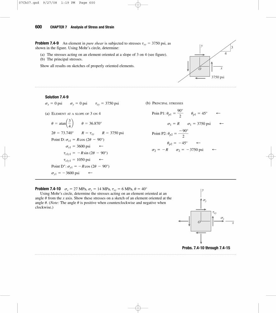
Problem 7.4-10 sx � 27 MPa, sy � 14 MPa, txy � 6 MPa, u � 40°Using Mohr’s circle, determine the stresses acting on an element oriented at an
angle u from the x axis. Show these stresses on a sketch of an element oriented at theangle u. (Note: The angle u is positive when counterclockwise and negative whenclockwise.)
y
xO
txy
sx
sy
600 CHAPTER 7 Analysis of Stress and Strain
Problem 7.4-9 An element in pure shear is subjected to stresses txy � 3750 psi, as shown in the figure. Using Mohr’s circle, determine:
(a) The stresses acting on an element oriented at a slope of 3 on 4 (see figure).(b) The principal stresses.
Show all results on sketches of properly oriented elements.O
3
4
y
x
3750 psi
Solution 7.4-9
(a) ELEMENT AT A SLOPE OF 3 ON 4
sy1 � �3600 psi ;Point Dœ: sy1 � �R cos (2u � 90°)
tx1y1 � 1050 psi ;tx1y1 � �R sin (2u � 90°)
sx1 � 3600 psi ;Point D: sx1 � R cos (2u � 90°)
2u � 73.740° R � txy R � 3750 psi
u � atana3
4b u � 36.870°
sx � 0 psi sy � 0 psi txy � 3750 psi (b) PRINCIPAL STRESSES
s2 � �R s2 � �3750 psi ;up2 � �45° ;
Point P2: up2 ��90°
2
s1 � R s1 � 3750 psi ;
Poin P1: up1 �90°
2 up1 � 45° ;
Probs. 7.4-10 through 7.4-15
07Ch07.qxd 9/27/08 1:19 PM Page 600

SECTION 7.4 Mohr’s Circle 601
Solution 7.4-10
a � atana txy
sx � saverb a � 42.71°
R � 2(sx � saver)2
+ txy
2 R � 8.8459 MPa
saver �sx + sy
2 saver � 20.50 MPa
u � 40°
sx � 27 MPa sy � 14 MPa txy � 6 MPa
sy1 � 13.46 MPa ;
Point Dœ: sy1 � saver � R cos (b)
tx1y1 � �5.36 MPa ;tx1y1 � �R sin (b)
;sx1 � 27.5 MPa
Point D: sx1 � saver + R cos (b)
b � 2u � a b � 37.29°
Problem 7.4-11 sx � 3500 psi, sy � 12,200 psi, txy � �3300 psi, u � �51°Using Mohr’s circle, determine the stresses acting on an element oriented at an angle u from the x axis. Show these stresses on a
sketch of an element oriented at the angle u. (Note: The angle u is positive when counterclockwise and negative when clockwise.)
Solution 7.4-11
a � atana txy
sx � saverb a � 37.18°
R � 2(sx � saver)2
+ txy
2 R � 5460 psi
saver �sx + sy
2 saver � 7850 psi
;u � �51°
sx � 3500 psi sy � 12200 psi txy � �3300 psi
;sy1 � 3718 psi
Point Dœ: sy1 � saver � R cos (b)
tx1y1 � �3569 psi ;tx1y1 � �R sin (b)
sx1 � 11982 psi ;
Point D: sx1 � saver + R cos (b)
b � 180° + 2u � a b � 40.82°
Problem 7.4-12 sx � �47 MPa, sy � �186 MPa, txy � �29 MPa, u � �33°Using Mohr’s circle, determine the stresses acting on an element oriented at an angle u from the x axis. Show these stresses on a
sketch of an element oriented at the angle u. (Note: The angle u is positive when counterclockwise and negative when clockwise.)
Solution 7.4-12
b � �2u � a b � 43.35°
a � atana ` txy
sx � saver` b a � 22.65°
R � 2(sx � saver)2
+ txy
2 R � 75.3077 MPa
saver �sx + sy
2 saver � �116.50 MPa
u � �33°
sx ��47MPa sy ��186MPa txy ��29MPa
sy1 � �171.3 MPa ;Point Dœ: sy1 � saver � R cos (b)
tx1y1 ��51.7 MPa ;tx1y1 ��R sin (b)
sx1 � �61.7 MPa ;
Point D: sx1 � saver + R cos (b)
07Ch07.qxd 9/27/08 1:19 PM Page 601

602 CHAPTER 7 Analysis of Stress and Strain
Problem 7.4-13 sx � �1720 psi, sy � �680 psi, txy � 320 psi, u � 14°Using Mohr’s circle, determine the stresses acting on an element oriented at an angle u from the x axis. Show these
stresses on a sketch of an element oriented at the angle u. (Note: The angle u is positive when counterclockwise and negativewhen clockwise.)
Solution 7.4-13
b � 2u + a b � 64.16°
a � atana txy
|sx � saver|b a � 36.16°
R � 2(sx � saver)2
+ txy
2 R � 644.0 psi
saver �sx + sy
2 saver � �1200 psi
u � 14°
sx � �1720 psi sy � �680 psi txy � 380 psi
sy1 � �919 psi ;Point Dœ: sy1 � saver + R cos (b)
tx1y1 � R sin (b) tx1y1 � 580 psi ;sx1 � �1481 psi ;
Point D: sx1 � saver � R cos(b)
Problem 7.4-14 sx � 33 MPa, sy � �9 MPa, txy � 29 MPa, u � 35°Using Mohr’s circle, determine the stresses acting on an element oriented at an angle u from the x axis. Show these
stresses on a sketch of an element oriented at the angle u. (Note: The angle u is positive when counterclockwise and negativewhen clockwise.)
Solution 7.4-14
b � 2u � a b � 15.91°
a � atana ` txy
sx � saver` b a � 54.09°
R � 2(sx � saver)2
+ txy2 R � 35.8050 MPa
saver �sx + sy
2 saver � 12.00 MPa
u � 35°
sx � 33 MPa sy � �9 MPa txy � 29 MPa
sy1 � �22.4 MPa ;Point Dœ : sy1 � saver � R cos (b)
tx1y1 � �9.81 MPa ;tx1y1 � �R sin (b)
sx1 � 46.4 MPa ;
Point D: sx1 � saver + R cos (b)
Problem 7.4-15 sx � �5700 psi, sy � 950 psi, txy � �2100 psi, u � 65°Using Mohr’s circle, determine the stresses acting on an element oriented at an angle u from the x axis. Show these
stresses on a sketch of an element oriented at the angle u. (Note: The angle u is positive when counterclockwise and negativewhen clockwise.)
07Ch07.qxd 9/27/08 1:19 PM Page 602

SECTION 7.4 Mohr’s Circle 603
Solution 7.4-15
b � 180° � 2u + a b � 82.28°
a � atana |txy|
|sx � saver|b a � 32.28°
R � 2(sx � saver)2
+ txy
2 R � 3933 psi
saver �sx + sy
2 saver � �2375 psi
u � 65°
sx � �5700 psi sy � 950 psi txy � �2100 psi
sy1 � �2904 psi ;Point Dœ: sy1 � saver � R cos (b)
tx1y1 � R sin (b) tx1y1 � 3897 psi ;sx1 � �1846 psi ;
Point D: sx1 � saver + R cos (b)
Problems 7.4-16 sx � �29.5 MPa, sy � 29.5 MPa, txy � 27 MPaUsing Mohr’s circle, determine (a) the principal stresses and (b) the maximum
shear stresses and associated normal stresses. Show all results on sketches of properlyoriented elements.
y
xO
txy
sx
sy
Solution 7.4-16
(a) PRINCIPAL STRESSES
up2 � up1 � 90° up2 � �21.2° ;
up1 �180° � a
2 up1 � 68.8° ;
a � atana ` txy
sx � saver` b a � 42.47°
R � 2(sx � saver)2
+ txy2 R � 39.9906 MPa
saver �sx + sy
2 saver � 0 MPa
sx � �29.5 MPa sy � 29.5 MPa txy � 27 MPa
(b) MAXIMUM SHEAR STRESSES
tmax � R tmax � 40.0 MPa ;
Point S1: saver � 0 MPa ;
us2 � 90° + us1 us2 � 113.8° ;
us1 �90°�a
2 us1 � 23.8° ;
Point P2: s2 � �R s2 � �40.0 MPa ;
Point P1: s1 � R s1 � 40.0 MPa ;
Probs. 7.4-16 through 7.4-23
07Ch07.qxd 9/27/08 1:19 PM Page 603

604 CHAPTER 7 Analysis of Stress and Strain
Problems 7.4-17 sx � 7300 psi, sy � 0 psi, txy � 1300 psiUsing Mohr’s circle, determine (a) the principal stresses and (b) the maximum shear stresses and associated normal
stresses. Show all results on sketches of properly oriented elements.
Solution 7.4-17
(a) PRINCIPAL STRESSES
up2 �a + 180°
2 up2 � 99.8°
;up1 �a
2 up1 � 9.80°
a � atana ` txy
sx � saver` b a � 19.60°
R � 2(sx � saver)2
+ txy2 R � 3875 psi
saver �sx + sy
2 saver � 3650 psi
sx � 7300 psi sy � 0 psi txy � 1300 psi
(b) MAXIMUM SHEAR STRESSES
tmax � R tmax � 3875 psi ;
Point S1: saver � 3650 psi ;
us2 � 90° + us1 us2 � 54.8°
us1 ��90° + a
2 us1 � �35.2°
s2 � �225 psi
Point P2: s2 � �R + saver
s1 � 7525 psi ;
Point P1: s1 � R + saver
Problems 7.4-18 sx � 0 MPa, sy � �23.4 MPa, txy � �9.6 MPaUsing Mohr’s circle, determine (a) the principal stresses and (b) the maximum shear stresses and associated normal
stresses. Show all results on sketches of properly oriented elements.
Solution 7.4-18
(a) PRINCIPAL STRESSES
up2 � up1 + 90° up2 � 70.32° ;
up1 ��a
2 up1 � �19.68° ;
a � atana ` txy
sx � saver` b a � 39.37°
R � 2(sx � saver)2
+ txy2 R � 15.1344 MPa
saver �sx + sy
2 saver � �11.70 MPa
sx � 0 MPa sy � �23.4 MPa txy � �9.6 MPa
(b) MAXIMUM SHEAR STRESSES
tmax � R tmax � 15.13 MPa ;Point S1: saver � �11.70 MPa
us2 � 90 ° + us1 us2 � 25.3°
us1 ��90° � a
2 us1 � �64.7° ;
s2 � �26.8 MPa ;Point P2: s2 � �R + saver
s1 � 3.43 MPa ;Point P1: s1 � R + saver
07Ch07.qxd 9/27/08 1:19 PM Page 604

SECTION 7.4 Mohr’s Circle 605
Problems 7.4-19 sx � 2050 psi, sy � 6100 psi, txy � 2750 psiUsing Mohr’s circle, determine (a) the principal stresses and (b) the maximum shear stresses and associated normal
stresses. Show all results on sketches of properly oriented elements.
Solution 7.4-19
(a) PRINCIPAL STRESSES
;up2 ��a
2 up2 � �26.8°
;up1 �180° � a
2 up1 � 63.2°
a � atana ` txy
sx � saver` b a � 53.63°
R � 2(sx � saver)2
+ txy2 R � 3415 psi
saver �sx + sy
2 saver � 4075 psi
sx � 2050 psi sy � 6100 psi txy � 2750 psi
(b) MAXIMUM SHEAR STRESSES
tmax � R tmax � 3415 psi ;
Point S1: saver � 4075 psi ;
us2 � 90° + us1 us2 � 71.8°
us1 ��90° + a
2 us1 � �18.2° ;
s2 � 660 psi ;
Point P2: s2 � �R + saver
s1 � 7490 psi ;
Point P1: s1 � R + saver
Problems 7.4-20 sx � 2900 kPa, sy � 9100 kPa, txy � �3750 kPaUsing Mohr’s circle, determine (a) the principal stresses and (b) the maximum shear stresses and associated normal
stresses. Show all results on sketches of properly oriented elements.
Solution 7.4-20
(a) PRINCIPAL STRESSES
up2 �a
2 up2 � 25.2° ;
;up1 �a + 180°
2 up1 � 115.2°
a � atana ` txy
sx � saver` b a � 50.42°
R � 2(sx � saver)2
+ txy2 R � 4865.4393 kPa
saver �sx + sy
2 saver � 6000 kPa
sx � 2900 kPa sy � 9100 kPa txy � �3750 kPa
(b) MAXIMUM SHEAR STRESSES
tmax � R tmax � 4865 kPa ;Point S1: saver � 6000 kPa ;
us2 � 90° + us1 us2 � 160.2° ;
us1 �90° + a
2 us1 � 70.2° ;
s2 � 1135 kPa ;Point P2: s2 � �R + saver
s1 � 10865 KPa ;
Point P1: s1 � R + saver
07Ch07.qxd 9/27/08 1:19 PM Page 605

606 CHAPTER 7 Analysis of Stress and Strain
Problems 7.4-21 sx � �11,500 psi, sy � �18,250 psi, txy � �7200 psiUsing Mohr’s circle, determine (a) the principal stresses and (b) the maximum shear stresses and associated normal
stresses. Show all results on sketches of properly oriented elements.
Solution 7.4-21
(a) PRINCIPAL STRESSES
up2 �180° � a
2 up2 � 57.6° ;
up1 ��a
2 up1 � �32.4° ;
a � atana ` txy
sx � saver` b a � 64.89°
R � 2(sx � saver)2
+ txy2 R � 7952 psi
saver �sx + sy
2 saver � �14875 psi
txy � �7200 psi
sx � �11500 psi sy � �18250 psi
(b) MAXIMUM SHEAR STRESSES
tmax � R tmax � 7952 psi ;Point S1: saver � �14875 psi ;
us2 � 90° + us1 us2 � 192.6°
;us1 �270° � a
2 us1 � 102.6°
s2 � �22827 psi ;Point P2: s2 � �R + saver
s1 � �6923 psi ;
Point P1: s1 � R + saver
Problems 7.4-22 sx � �3.3 MPa, sy � 8.9 MPa, txy � �14.1 MPaUsing Mohr’s circle, determine (a) the principal stresses and (b) the maximum shear stresses and associated normal
stresses. Show all results on sketches of properly oriented elements.
Solution 7.4-22
a � atana ` txy
sx � saver` b a � 66.6°
R � 2(sx � saver)2
+ txy2 R � 15.4 MPa
saver �sx + sy
2 saver � 2.8 MPa
txy ��14.1 MPa
sx ��3.3 MPa sy � 8.9 MPa (a) PRINCIPAL STRESSES
Point P2: s2 � �R + saver
s1 � 18.2 MPa ;
Point P1: s1 � R + saver
up2 �a
2 up2 � 33.3°
;up1 �a + 180°
2 up1 � 123.3°
07Ch07.qxd 9/27/08 1:19 PM Page 606

SECTION 7.4 Mohr’s Circle 607
Problems 7.4-23 sx � 800 psi, sy � �2200 psi, txy � 2900 psiUsing Mohr’s circle, determine (a) the principal stresses and (b) the maximum shear stresses and associated normal
stresses. Show all results on sketches of properly oriented elements.
Solution 7.4-23
(a) PRINCIPAL STRESSES
;up2 �180° + a
2 up2 � 121.3°
;up1 �a
2 up1 � 31.3°
a � atana ` txy
sx � saver` b a � 62.65°
R � 2(sx � saver)2
+ txy2 R � 3265 psi
saver �sx + sy
2 saver � �700 psi
sx � 800 psi sy � �2200 psi txy � 2900 psi
(b) MAXIMUM SHEAR STRESSES
tmax � R tmax � 3265 psi
Point S1: saver � �700 psi ;
us2 � 90° + us1 us2 � 76.3° ;
us1 ��90° + a
2 us1 � �13.7° ;
s2 � �3965 psi ;
Point P2: s2 � �R + saver
s1 � 2565 psi ;
Point P1: s1 � R + saver
(b) MAXIMUM SHEAR STRESSES
us1 �90° + a
2 us1 � 78.3°
s2 � �12.6 MPa ;
tmax � R tmax � 15.4 MPa ;Point S1: saver � 2.8 MPa ;
us2 � 90° + us1 us2 � 168.3°
07Ch07.qxd 9/27/08 1:19 PM Page 607

608 CHAPTER 7 Analysis of Stress and Strain
Hooke’s Law for Plane StressWhen solving the problems for Section 7.5, assume that the material is linearly elastic with modulus of elasticity E and Poisson’s ratio n.
Problem 7.5-1 A rectangular steel plate with thickness t � 0.25 in. is subjected to uniform normal stresses �x and �y, as shown in the figure. Strain gages A and B, oriented in the x and y directions, respectively, are attached to the plate. The gage readings give normal strains ex � 0.0010 (elongation) and ey � �0.0007 (shortening).
Knowing that E � 30 � 106 psi and � � 0.3, determine the stresses �x and �y and the change �t in the thickness of the plate.
sy
sx
y
xOB A
Solution 7.5-1 Rectangular plate in biaxial stress
SUBSTITUTE NUMERICAL VALUES:
Eq. (7-40a):
Eq. (7-40b):
sy �E
(1 � �)2(ây + �âx) � �13,190 psi ;
sx �E
(1 � �)2(âx + �ây) � 26,040 psi ;
E � 30 * 106 psi � � 0.3
t � 0.25 in. âx � 0.0010 ây � �0.0007 Eq. (7-39c):
(Decrease in thickness)
¢t � âzt � �32.1 * 10�6 in. ;
âz � ��
E (sx + sy) � �128.5 * 10�6
Problem 7.5-2 Solve the preceding problem if the thickness of the steel plate is t � 10 mm, the gage readings are ex � 480 � 10�6 (elongation) and ey � 130 � 10�6 (elongation), the modulus is E � 200 GPa, and Poisson’s ratio is � � 0.30.
Solution 7.5-2 Rectangular plate in biaxial stress
SUBSTITUTE NUMERICAL VALUES:
Eq. (7-40a):
sx �E
(1 � �)2 (âx + �ây) � 114.1 MPa ;
E � 200 GPa � � 0.3
ây � 130 * 10�6
t � 10 mm âx � 480 * 10�6 Eq. (7-40b):
Eq. (7-39c):
(Decrease in thickness)
¢t � âz t � �2610 * 10�6 mm ;
âz � ��
E (sx + sy) � �261.4 * 10�6
sy �E
(1 � �)2 (ây + �âx) � 60.2 MPa ;
Probs. 7.5-1 and 7.5-2
07Ch07.qxd 9/27/08 1:20 PM Page 608

Problem 7.5-3 Assume that the normal strains and for an element in plane stress (see figure) are measured with strain gages.
(a) Obtain a formula for the normal strain in the direction in terms of , and Poisson’s ratio .
(b) Obtain a formula for the dilatation in terms of , and Poisson’s ratio .�
Px, Pye�Px, Py
zPz
PyPx y
x
z
Osx
txy
sy
Solution 7.5-3 Plane stressGiven:
(a) NORMAL STRAIN
Eq. (7-34c):
Eq. (7-36a):
Eq. (7-36b):
Substitute and into the first equation and simplify:
âz � ��
1 � � (âx + ây) ;
sysx
sy �E
(1 � �2) (ây + �âx)
sx �E
(1 � �2) (âx + �ây)
âz � ��
E (sx + sy)
âz
âx, ây, � (b) DILATATION
Eq. (7-47):
Substitute and from above and simplify:
e �1 � 2�
1 � � (âx + ây) ;
sysx
e �1 � 2�
E (sx + sy)
Problem 7.5-4 A magnesium plate in biaxial stress is subjected to tensile stresses sx� 24 MPa and sy� 12 MPa (see figure). The corresponding strains in the plate are �x � 440 � 10�6 and �y � 80 � 10�6.
Determine Poisson’s ratio and the modulus of elasticity Efor the material.
�
sy
sx
y
xO
Solution 7.5-4 Biaxial stress
POISSON’S RATION AND MODULUS OF ELASTICITY
Eq. (7-39a):
Eq. (7-39b): ây �1
E (sy � �sx)
âx �1
E (sx � �sy)
âx � 440 * 10�6 ây � 80 * 10�6
sx � 24 MPa sy � 12 MPa Substitute numerical values:
Solve simultaneously:
� � 0.35 E � 45 GPa ;
E (80 * 10�6) � 12 MPa � � (24 MPa)
E (440 * 10�6) � 24 MPa � � (12 MPa)
SECTION 7.5 Hooke’s Law for Plane Stress 609
Probs. 7.5-4 through 7.5-7
07Ch07.qxd 9/27/08 1:20 PM Page 609

610 CHAPTER 7 Analysis of Stress and Strain
Problem 7.5-5 Solve the preceding problem for a steel plate with sx � 10,800 psi (tension), sy� �5400 psi (compres-sion), ex � 420 � 10�6 (elongation), and ey � �300 � 10�6 (shortening).
Solution 7.5-5 Biaxial stress
POISSON’S RATIO AND MODULUS OF ELASTICITY
Eq. (7-39a):
Eq. (7-39b): ây �1
E (sy � �sx)
âx �1
E (sx � �sy)
âx � 420 * 10�6 ây � �300 * 10�6
sx � 10,800 psi sy � �5400 psi Substitute numerical values:
Solve simultaneously:
� � 1/3 E � 30 * 106 psi ;
E (�300 * 10�6) � �5400 psi � � (10,800 psi)
E (420 * 10�6) � 10,800 psi � � (�5400 psi)
Problem 7.5-6 A rectangular plate in biaxial stress (see figure) is subjected to normal stresses �x� 90 MPa (tension) and�y� �20 MPa (compression). The plate has dimensions and is made of steel with and
.
(a) Determine the maximum in-plane shear strain in the plate.(b) Determine the change in the thickness of the plate.(c) Determine the change in the volume of the plate.¢V
¢tgmax
� � 0.30E � 200 GPa400 * 800 * 20 mm
Solution 7.5-6 Biaxial stress
Dimensions of Plate: Shear Modulus (Eq. 7-38):
(a) MAXIMUM IN-PLANE SHEAR STRAIN
Principal stresses:
Eq. (7-26):
Eq. (7-35): gmax �tmax
G� 715 * 10�6 ;
tmax �s1 � s2
2� 55.0 MPa
s1 � 90 MPa s2 � �20 MPa
G �E
2(1 + �)� 76.923 GPa
400 mm * 800 mm * 20 mm
E � 200 GPa � � 0.30
sx � 90 MPa sy � �20 MPa (b) CHANGE IN THICKNESS
Eq. (7-39c):
(Decrease in thickness)
(c) CHANGE IN VOLUME
From Eq. (7-47):
Also,
(Increase in volume)
� 896 mm3 ;‹ ¢V � (6.4 * 106 mm3)(140 * 10�6)
a1 � 2�
Eb(sx + sy) � 140 * 10�6
V0 � (400)(800)(20) � 6.4 * 106 mm3
¢V � V0a1 � 2�
Eb(sx + sy)
¢t � âz t � �2100 * 10�6 mm ;
âz � ��
E (sx + sy) � �105 * 10�6
07Ch07.qxd 9/27/08 1:20 PM Page 610

SECTION 7.5 Hooke’s Law for Plane Stress 611
Problem 7.5-7 Solve the preceding problem for an aluminum plate with sx� 12,000 psi (tension), sy� �3,000 psi (compression), dimensions 20 � 30 � 0.5 in., E � 10.5 � 106 psi, and .� � 0.33
Solution 7.5-7 Biaxial stress
Dimensions of Plate: .Shear Modulus (Eq. 7-38):
(a) MAXIMUM IN-PLANE SHEAR STRAIN
Principal stresses:
Eq. (7-26):
Eq. (7-35): gmax �tmax
G� 1,900 * 10�6 ;
tmax �s1 � s2
2� 7,500 psi
s2 � �3,000 psi
s1 � 12,000 psi
G �E
2(1 + �)� 3.9474 * 106 psi
20 in. * 30 in. * 0.5 in
E � 10.5 * 106 psi � � 0.33
sx � 12,000 psi sy � �3,000 psi (b) CHANGE IN THICKNESS
Eq. (7-39c):
(Decrease in thickness)
(c) CHANGE IN VOLUME
From Eq. (7-47):
Also,
(Increase in volume)
� 0.0874 in.3 ;‹ ¢V � (300 in.3)(291.4 * 10�6)
a1 � 2�
Eb(sx + sy) � 291.4 * 10�6
V0 � (20)(30)(0.5) � 300 in.3
¢V � V0 a1 � 2�
Eb(sx + sy)
¢t � âz t � �141 * 10�6 in. ;� �282.9 * 10�6
âz � ��
E (sx + sy)
Problem 7.5-8 A brass cube 50 mm on each edge is compressed in two perpendicular directions by forces P � 175 kN (see figure).
Calculate the change �V in the volume of the cube and the strain energy U stored in the cube, assuming E � 100 GPa and � � 0.34.
P = 175 kN
P = 175 kN
Solution 7.5-8 Biaxial stress-cube
Side
E � 100 GPa � � 0.34 ( Brass)
b � 50 mm P � 175 kN
CHANGE IN VOLUME
Eq. (7-47):
(Decrease in volume)
;¢V � eV0 � �56 mm3
V0 � b3 � (50 mm)3 � 125 * 103mm3
e �1 � 2�
E (sx + sy) � �448 * 10�6
sx � sy � �P
b2� �
(175 kN)
(50 mm)2� �70.0 MPa
07Ch07.qxd 9/27/08 1:20 PM Page 611

612 CHAPTER 7 Analysis of Stress and Strain
STRAIN ENERGY
Eq. (7-50):
� 0.03234 MPa
u �1
2E (sx
2+ sy
2 � 2�sxsy)� 4.04 J ;
U � uV0 � (0.03234 MPa)(125 * 103 mm3)
Problem 7.5-9 A 4.0-inch cube of concrete is compressed in biaxial stress by means of a framework that is loaded as shown in the figure.
Assuming that each load equals 20 k, determine the change in the volume of the cube and the strain energy stored in the cube.U
¢VF
(E � 3.0 * 106 psi, � � 0.1)
F
F
Solution 7.5-9 Biaxial stress – concrete cube
Joint :
sx � sy � �P
b2 � �1768 psi
� 28.28 kips
P � F12
A
CHANGE IN VOLUME
Eq. (7-47):
(Decrease in volume)
STRAIN ENERGY
Eq. (7-50):
U � uV0 � 60.0 in.-lb ;� 0.9377 psi
u �1
2E (sx
2+ sy
2 � 2�sxsy)
¢V � eV0 � �0.0603 in.3 ;V0 � b3 � (4 in.)3 � 64 in.3
e �1 � 2�
E (sx + sy) � �0.0009429.
F � 20 kips
� � 0.1
E � 3.0 * 106 psi
b � 4 in
Problem 7.5-10 A square plate of width b and thickness t is loaded by normal forces and , and by shear forces V, as shown in the figure. These forces produce uniformly distributed stresses acting on the side faces of the place.
Calculate the change �V in the volume of the plate and the strain energy U stored in the plate if the dimensions are b � 600 mm and t � 40 mm, the plate is made of magnesium with E � 45 GPa and v � 0.35, and the forces are Px � 480 kN, Py � 180 kN, and V � 120 kN.
Probs. 7.5-10 and 7.5-11
PyPx
Py
Py
PxPx
y
t
b
b
V
V
V
V
xO
07Ch07.qxd 9/27/08 1:20 PM Page 612

SECTION 7.5 Hooke’s Law for Plane Stress 613
Solution 7.5-10 Square plate in plane stress
CHANGE IN VOLUME
Eq. (7-47): e �1 � 2�
E (sx + sy) � 183.33 * 10�6
txy �V
bt� 5.0 MPaV � 120 kN
sy �Py
bt� 7.5 MPaPy � 180 kN
sx �Px
bt� 20.0 MPa Px � 480 kN
v � 0.35 (magnesium)E � 45 GPa
t � 40 mmb � 600 mm
(Increase in volume)
STRAIN ENERGY
Eq. (7-50):
Substitute numerical values:
U � uV0 � 67.0 N # m � 67.0 J ;u � 4653 Pa
G �E
2(1 + �)� 16.667 GPa
u �1
2E(sx
2+ sy
2 � 2�sxsy) +
txy2
2G
¢V � eV0 � 2640 mm3 ;V0 � b2t � 14.4 * 106 mm3
Problem 7.5-11 Solve the preceding problem for an aluminum plate with , , , ,, , and .V � 15 kPy � 20 kPx � 90 k
� � 0.33E � 10,600 ksit � 1.0 in.b � 12 in.
Solution 7.5-11 Square plate in plane stress
CHANGE IN VOLUME
Eq. (7-47):
(Increase in volume)
¢V � eV0 � 0.0423 in.3 ;V0 � b2t � 144 in.3
e �1 � 2�
E(sx + sy) � 294 * 10�6
V � 15 k txy �V
bt� 1250 psi
Py � 20 k sy �Py
bt� 1667 psi
Px � 90 k sx �Px
bt� 7500 psi
E � 10,600 ksi � � 0.33 ( aluminum)
b � 12.0 in. t � 1.0 in. STRAIN ENERGY
Eq. (7-50):
Substitute numerical values:
U � uV0 � 373 in.-lb ;u � 2.591 psi
G �E
2(1 + �)� 3985 ksi
u �1
2E (sx
2+ sy
2 � 2�sxsy) +
txy2
2G
07Ch07.qxd 9/27/08 1:20 PM Page 613

614 CHAPTER 7 Analysis of Stress and Strain
Problem 7.5-12 A circle of diameter d � 200 mm is etched on a brass plate (see figure). The plate has dimensions 400 � 400 � 20 mm. Forces are applied to the plate, producing uniformly distributed normal stresses �x � 42 MPa and �y � 14 MPa.
Calculate the following quantities: (a) the change in length �acof diameter ac; (b) the change in length �bd of diameter bd; (c) the change �t in the thickness of the plate; (d) the change �V in the volume of the plate, and (e) the strain energy U stored in the plate. (Assume E � 100 GPa and v � 0.34.)
sy
sx
sx
sy
yz
b
d
ca
x
Solution 7.5-12 Plate in biaxial stress
Dimensions:Diameter of circle:
(a) CHANGE IN LENGTH OF DIAMETER IN DIRECTION
Eq. (7-39a):
(increase)
(b) CHANGE IN LENGTH OF DIAMETER IN DIRECTION
Eq. (7-39b):
(decrease)� �560 * 10�6 mm ;
¢bd � ây d
ây �1
E(sy � �sx) � �2.80 * 10�6
y
¢ac � âx d � 0.0745 mm ;
âx �1
E(sx � �sy) � 372.4 * 10�6
x
E � 100 GPa � � 0.34 (Brass)
d � 200 mm400 * 400 * 20 (mm)
sx � 42 MPa sy � 14 MPa (c) CHANGE IN THICKNESS
Eq. (7-39c):
(decrease)
(d) CHANGE IN VOLUME
Eq. (7-47):
(increase)
(e) STRAIN ENERGY
Eq. (7-50):
U � uV0 � 25.0 N # m � 25.0 J ;� 7.801 * 10�3 MPa
u �1
2E(sx
2+ sy
2 � 2�sx sy)
¢V � eV0 � 573 mm3 ;V0 � (400)(400)(20) � 3.2 * 106 mm3
e �1 � 2�
E(sx + sy) � 179.2 * 10�6
¢t � âz t � �0.00381 mm ;� �190.4 * 10�6
âz � ��
E (sx + sy)
07Ch07.qxd 9/27/08 1:20 PM Page 614
SECTION 7.6 Triaxial Stress 615
Triaxial StressWhen solving the problems for Section 7.6, assume that the material is linearly elastic with modulus of elasticity E and Poisson’s ratio n.
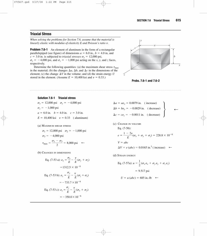
Problem 7.6-1 An element of aluminum in the form of a rectangularparallelepiped (see figure) of dimensions ., , and
. is subjected to triaxial stresses ,, and acting on the , and faces,
respectively.Determine the following quantities: (a) the maximum shear stress
in the material; (b) the changes , and in the dimensions of theelement; (c) the change in the volume; and (d) the strain energy stored in the element. (Assume and .)
Probs. 7.6-1 and 7.6-2� � 0.33E � 10,400 ksi
U¢V¢c¢a, ¢b
tmax
zx, ysz � �1,000 psisy � �4,000 psisx � 12,000 psic � 3.0 in
b � 4.0 ina � 6.0 in
y
x
z
a
b
c
O
Solution 7.6-1 Triaxial stress
(a) MAXIMUM SHEAR STRESS
(b) CHANGES IN DIMENSIONS
��350.0 * 10�6
Eq. (7-53 c): âz �sz
E�
�
E (sx + sy)
��733.7 * 10�6
Eq. (7- 53 b): ây �sy
E�
�
E (sz + sx)
�1312.5 * 10�6
Eq. (7-53 a): âx �sx
E�
�
E (sy + sz)
tmax �s1 � s3
2� 8,000 psi ;
s3 � �4,000 psi
s1 � 12,000 psi s2 � �1,000 psi
E � 10,400 ksi � � 0.33 ( aluminum)
a � 6.0 in. b � 4.0 in. c � 3.0 in.
sz � �1,000 psi
sx � 12,000 psi sy � �4,000 psi
(c) CHANGE IN VOLUME
Eq. (7-56):
(d) STRAIN ENERGY
U � u (abc) � 685 in.-lb ;
� 9.517 psi
Eq. (7-57a): u �1
2 (sx âx + sy ây + sz âz)
¢V � e (abc) � 0.0165 in.3 ( increase) ;V � abc
e �1 � 2�
E(sx + sy + sz) � 228.8 * 10�6
¢c � câz � �0.0011 in. ( decrease)
¢b � bây � �0.0029 in. ( decrease)
¢a � aâx � 0.0079 in. ( increase)
M ;
07Ch07.qxd 9/27/08 1:22 PM Page 615

616 CHAPTER 7 Analysis of Stress and Strain
Problem 7.6-2 Solve the preceding problem if the element is steel ( = 200 GPA, ) with dimensions = 300 mm,= 150 mm, and = 150 mm and the stresses are , , and .sz � �40 MPasy � �40 MPasx � �60 MPacb
a� � 0.30E
Solution 7.6-2 Triaxial stress
(a) MAXIMUM SHEAR STRESS
(b) CHANGES IN DIMENSIONS
Eq. (7-53 c): âz �sz
E�
�
E (sx + sy) � �50.0 * 10�6
Eq. (7-53 b): ây �sy
E�
�
E (sz + sx) � �50.0 * 10�6
Eq. (7-53 a): âx �sx
E�
�
E (sy + sz) � �180.0 * 10�6
tmax �s1 � s3
2� 10.0 MPa ;
s3 � �60 MPa
s1 � �40 MPa s2 � �40 MPa
E � 200 GPa � � 0.30 (steel)
a � 300 mm b � 150 mm c � 150 mm
sz � �40 MPa
sx � �60 MPa sy � �40 MPa
(c) CHANGE IN VOLUME
Eq. (7-56):
(d) STRAIN ENERGY
U � u (abc) � 50.0 N # m � 50.0 J ;
� 0.00740 MPa
Eq. (7-57 a): u �1
2 (sx âx + sy ây + sz âz)
¢V � e(abc) � �1890 mm3 (decrease) ;V � abc
e �1 � 2�
E (sx + sy + sz) � �280.0 * 10�6
¢c � câz � �0.0075 mm. (decrease)
¢b � bây � �0.0075 mm (decrease)
¢a � aâx � �0.0540 mm (decrease)
M ;
Problem 7.6-3 A cube of cast iron with sides of length = 4.0 in. (see figure) is tested in a laboratory under triaxial stress. Gages mountedon the testing machine show that the compressive strains in the materialare and
Determine the following quantities: (a) the normal stresses , andacting on the , and faces of the cube; (b) the maximum shear
stress in the material; (c) the change in the volume of thecube; and (d) the strain energy stored in the cube. (Assume = 14,000ksi and .)
Probs. 7.6-3 and 7.6-4
� � 0.25EU
¢Vtmax
zx, ysz
sx, sy
Py � Pz � �37.5 * 10�6.Px � �225 * 10�6
a y
x
z
a
a
a
O
07Ch07.qxd 9/27/08 1:22 PM Page 616
SECTION 7.6 Triaxial Stress 617
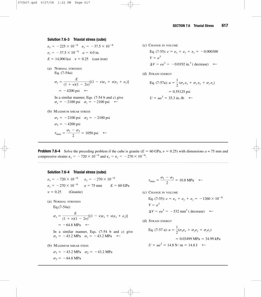
Solution 7.6-3 Triaxial stress (cube)
(a) NORMAL STRESSES
Eq. (7-54a):
In a similar manner, Eqs. (7-54 b and c) give
(b) MAXIMUM SHEAR STRESS
tmax �s1 � s3
2� 1050 psi ;
s3 � �4200 psi
s1 � �2100 psi s2 � �2100 psi
sy � �2100 psi sz � �2100 psi ;
� �4200 psi ;
sx �E
(1 + �)(1 � 2�)[(1 � �)âx + �(ây + âz)]
E � 14,000 ksi � � 0.25 (cast iron)
âz � �37.5 * 10�6 a � 4.0 in.
âx � �225 * 10�6 ây � �37.5 * 10�6 (c) CHANGE IN VOLUME
(d) STRAIN ENERGY
U � ua3 � 35.3 in.-lb ;� 0.55125 psi
Eq. (7-57a): u �1
2 (sx âx + sy ây + sz âz)
¢V � ea3 � �0.0192 in.3 ( decrease) ;V � a3
Eq. (7-55): e � âx + ây + âz � �0.000300
Problem 7.6-4 Solve the preceding problem if the cube is granite ( ) with dimensions = 75 mm andcompressive strains and Py � Pz � �270 * 10�6.Px � �720 * 10�6
aE � 60 GPa, � � 0.25
Solution 7.6-4 Triaxial stress (cube)
(a) NORMAL STRESSES
Eq.(7-54a):
In a similar manner, Eqs. (7-54 b and c) give
(b) MAXIMUM SHEAR STESS
s3 � �64.8 MPa
s1 � �43.2 MPa s2 � �43.2 MPa
sy � �43.2 MPa sz � �43.2 MPa ;
� �64.8 MPa ;
sx �E
(1 + �)(1 � 2�)[(1 � �)âx + �(âx + âz)]
� � 0.25 (Granite)
âz � �270 * 10�6 a � 75 mm E � 60 GPa
âx � �720 * 10�6 ây � �270 * 10�6
(c) CHANGE IN VOLUME
(d) STRAIN ENERGY
U � ua3 � 14.8 N # m � 14.8 J ;� 0.03499 MPa � 34.99 kPa
Eq. (7-57 a): u �1
2(sxâx + syây + szâz)
¢V � ea3 � �532 mm3 ( decrease) ;V � a3
Eq. (7-55): e � âx + ây + âz � �1260 * 10�6
tmax �s1 � s3
2� 10.8 MPa ;
07Ch07.qxd 9/27/08 1:22 PM Page 617
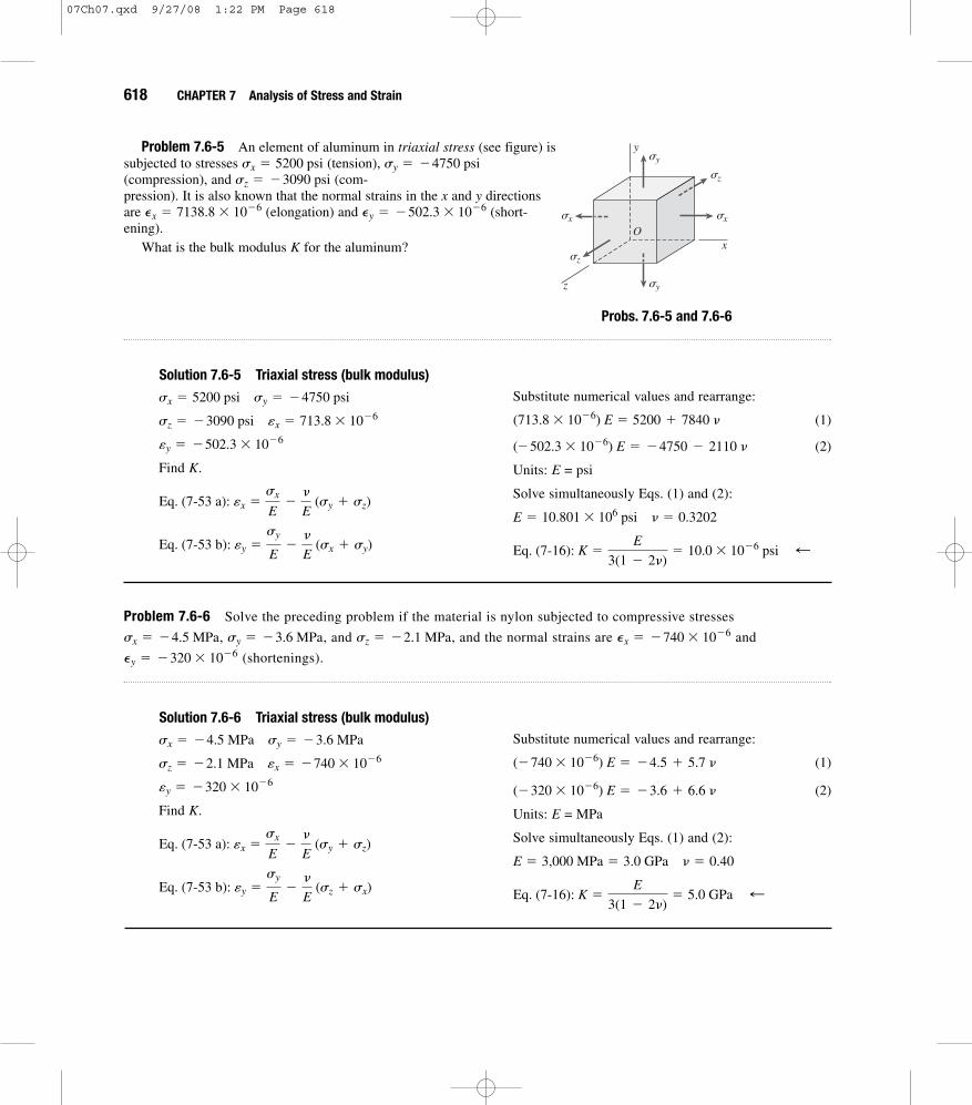
618 CHAPTER 7 Analysis of Stress and Strain
Problem 7.6-5 An element of aluminum in triaxial stress (see figure) is subjected to stresses (tension), (compression), and (com-pression). It is also known that the normal strains in the x and y directionsare (elongation) and (short-ening).
What is the bulk modulus for the aluminum?
Probs. 7.6-5 and 7.6-6
K
Py � �502.3 * 10�6Px � 7138.8 * 10�6
sz � �3090 psisy � �4750 psisx � 5200 psi
Solution 7.6-5 Triaxial stress (bulk modulus)
Find .
Eq. (7-53 b): ây �sy
E�
�
E (sx + sy)
Eq. (7-53 a): âx �sx
E�
�
E (sy + sz)
K
ây � �502.3 * 10�6
sz � �3090 psi âx � 713.8 * 10�6
sx � 5200 psi sy � �4750 psi Substitute numerical values and rearrange:
(1)
(2)
Units: = psi
Solve simultaneously Eqs. (1) and (2):
Eq. (7-16): K �E
3(1 � 2�)� 10.0 * 10�6 psi ;
E � 10.801 * 106 psi � � 0.3202
E
(�502.3 * 10�6) E � �4750 � 2110 �
(713.8 * 10�6) E � 5200 + 7840 �
y
x
z
Osxsx
sz
sy
sy
sz
Problem 7.6-6 Solve the preceding problem if the material is nylon subjected to compressive stresses
, , and , and the normal strains are and
(shortenings).Py � �320 * 10�6
Px � �740 * 10�6sz � �2.1 MPasy � �3.6 MPasx � �4.5 MPa
Solution 7.6-6 Triaxial stress (bulk modulus)
Find .
Eq. (7-53 b): ây �sy
E�
�
E (sz + sx)
Eq. (7-53 a): âx �sx
E�
�
E (sy + sz)
K
ây � �320 * 10�6
sz � �2.1 MPa âx � �740 * 10�6
sx � �4.5 MPa sy � �3.6 MPa Substitute numerical values and rearrange:
(1)
(2)
Units: = MPa
Solve simultaneously Eqs. (1) and (2):
Eq. (7-16): K �E
3(1 � 2�)� 5.0 GPa ;
E � 3,000 MPa � 3.0 GPa � � 0.40
E
(�320 * 10�6) E � �3.6 + 6.6 �
(�740 * 10�6) E � �4.5 + 5.7 �
07Ch07.qxd 9/27/08 1:22 PM Page 618

SECTION 7.6 Triaxial Stress 619
Problem 7.6-7 A rubber cylinder of length and cross-sectionalarea is compressed inside a steel cylinder by a force thatapplies a uniformly distributed pressure to the rubber (see figure).
(a) Derive a formula for the lateral pressure between therubber and the steel. (Disregard friction between the rubberand the steel, and assume that the steel cylinder is rigid whencompared to the rubber.)
(b) Derive a formula for the shortening of the rubber cylinder.d
p
FSALR
LS
R
F
S
F
Solution 7.6-7 Rubber cylinder
(a) LATERAL PRESSURE
or 0 � �p � �a�F
A� pb
Eq. (7-53 a): âx �sx
E�
�
E (sy + sz)
âx � âz � 0
sz � �p
sx � �p sy � �F
A
(b) SHORTENING
Substitute for and simplify:
(Positive represents an increase in strain, that is,elongation.)
(Positive represents a shortening of the rubbercylinder.)
d
d �(1 + �)(1 � 2�)
(1 � �)aFL
EAb ;
d � �âyL
ây
ây �F
EA
(1 + �)(�1 + 2�)
1 � �
p
� �F
EA�
�
E (�2p)
Eq. (7-53 b): ây �sy
E�
�
E (sz + sx)
Solve for p: p �v
1 � v aF
Ab ;
Problem 7.6-8 A block of rubber is confined between plane parallel walls of a steel block (see figure). A uniformly dis-tributed pressure is applied to the top of the rubber block bya force .
(a) Derive a formula for the lateral pressure between therubber and the steel. (Disregard friction between therubber and the steel, and assume that the steel block isrigid when compared to the rubber.)
(b) Derive a formula for the dilatation of the rubber.(c) Derive a formula for the strain-energy density of the
rubber.u
e
p
Fp0
SR
FF
SR
S
07Ch07.qxd 9/27/08 1:22 PM Page 619

620 CHAPTER 7 Analysis of Stress and Strain
Solution 7.6-8 Block of rubber
(a) LATERAL PRESSURE
OR 0 � �p � � (�p0) ‹ p � �p0 ;
Eq. (7-53 a): âx �sx
E�
�
E (sy + sz)
âx � 0 ây Z 0 âz Z 0
sy � �p0 sz � 0
sx � �p
(b) DILATATION
Substitute for :
(c) STRAIN ENERGY DENSITY
Eq. (7-57b):
Substitute for and :
u �(1 � �2)p0
2
2E ;
psx, sy, sz,
u �1
2E (sx
2+ sy
2+ sz
2) �v
E (sx sy + sx sz + sy sz)
e � �(1 + �)(1 � 2�)p0
E ;
p
�1 � 2�
E (�p � p0)
Eq. (7-56): e �1 � 2�
E (sx + sy + sz)
Problem 7.6-9 A solid spherical ball of brass ( ) is lowered into the ocean to a depth of 10,000 ft.The diameter of the ball is 11.0 in.
Determine the decrease in diameter, the decrease in volume, and the strain energy of the ball.U¢V¢d
� � 0.34E � 15 * 106 psi
Solution 7.6-9 Brass sphere
Lowered in the ocean to depth
Diameter
Sea water:
Pressure:
DECREASE IN DIAMETER
(decrease) ¢d � â0d � 1.04 * 10�3 in. ;
Eq. (7-59): â0 �s0
E(1 � 2�) � 94.53 * 10�6
s0 � gh � 638,000 lb/ft2 � 4431 psi
g � 63.8 lb/ft3d � 11.0 in.
h � 10,000 ft
E � 15 * 10�6 psi � � 0.34 DECREASE IN VOLUME
(decrease)
STRAIN ENERGY
U � uV0 � 438 in.-lb ;
u �3(1 � 2�)s0
2
2E� 0.6283 psi
Use Eq. (7-57 b) with sx � sy � sz � s0:
¢V � eV0 � 0.198 in.3 ;
V0 �4
3pr 3 �
4
3(p)a11.0 in.
2b3
� 696.9 in.3
Eq. (7-60): e � 3â0 � 283.6 * 10�6
07Ch07.qxd 9/27/08 1:22 PM Page 620

SECTION 7.6 Triaxial Stress 621
Problem 7.6-10 A solid steel sphere ( , = 0.3) is subjected to hydrostatic pressure such that its volume isreduced by 0.4%.
(a) Calculate the pressure .(b) Calculate the volume modulus of elasticity for the steel.(c) Calculate the strain energy stored in the sphere if its diameter is d � 150 mmU
Kp
p�E � 210 GPa
Solution 7.6-10 Steel sphere
Hydrostatic Pressure. = Initial volume
(a) PRESSURE
Pressure ;p � s0 � 700 MPa
or s0 �Ee
3(1 � 2�)� 700 MPa
Eq.(7-60): e �3s0(1 � 2�)
E
Dilatation: e �¢V
V0� 0.004
¢V � 0.004 V0
V0
E � 210 GPa � � 0.3 (b) VOLUME MODULUS OF ELASTICITY
(c) STRAIN ENERGY ( = diameter)= 150 mm r = 75 mm
From Eq. (7-57b) with
U � uV0 � 2470 N # m � 2470 J ;
V0 �4pr 3
3� 1767 * 10�6 m3
u �3(1 � 2�)s0
2
2E� 1.40 MPa
sx � sy � sz � s0:d
d
Eq. (7-63): K �s0
E�
700 MPa
0.004� 175 GPa ;
Problem 7.6-11 A solid bronze sphere (volume modulus of elasticity K � 14.5 � 106 psi) is suddenly heated around itsouter surface. The tendency of the heated part of the sphere to expand produces uniform tension in all directions at the centerof the sphere.
If the stress at the center is 12,000 psi, what is the strain? Also, calculate the unit volume change e and the strain-energydensity u at the center.
Solution 7.6-11 Bronze sphere (heated)
(tension at the center)
STRAIN AT THE CENTER OF THE SPHERE
Combine the two equations:
â0 �s0
3K� 276 * 10�6 ;
Eq. (7-61): K �E
3(1 � 2�)
Eq. (7-59): â0 �s0
E(1 � 2�)
s0 � 12,000 psiK � 14.5 * 106 psi UNIT VOLUME CHANGE AT THE CENTER
STRAIN ENERGY DENSITY AT THE CENTER
u � 4.97 psi ;
u �3(1 � 2�)s0
2
2E�
s20
2K
Eq. (7-57b) with sx � sy � sz � s0:
Eq. (7-62): e �s0
K� 828 * 10�6 ;
07Ch07.qxd 9/27/08 1:22 PM Page 621
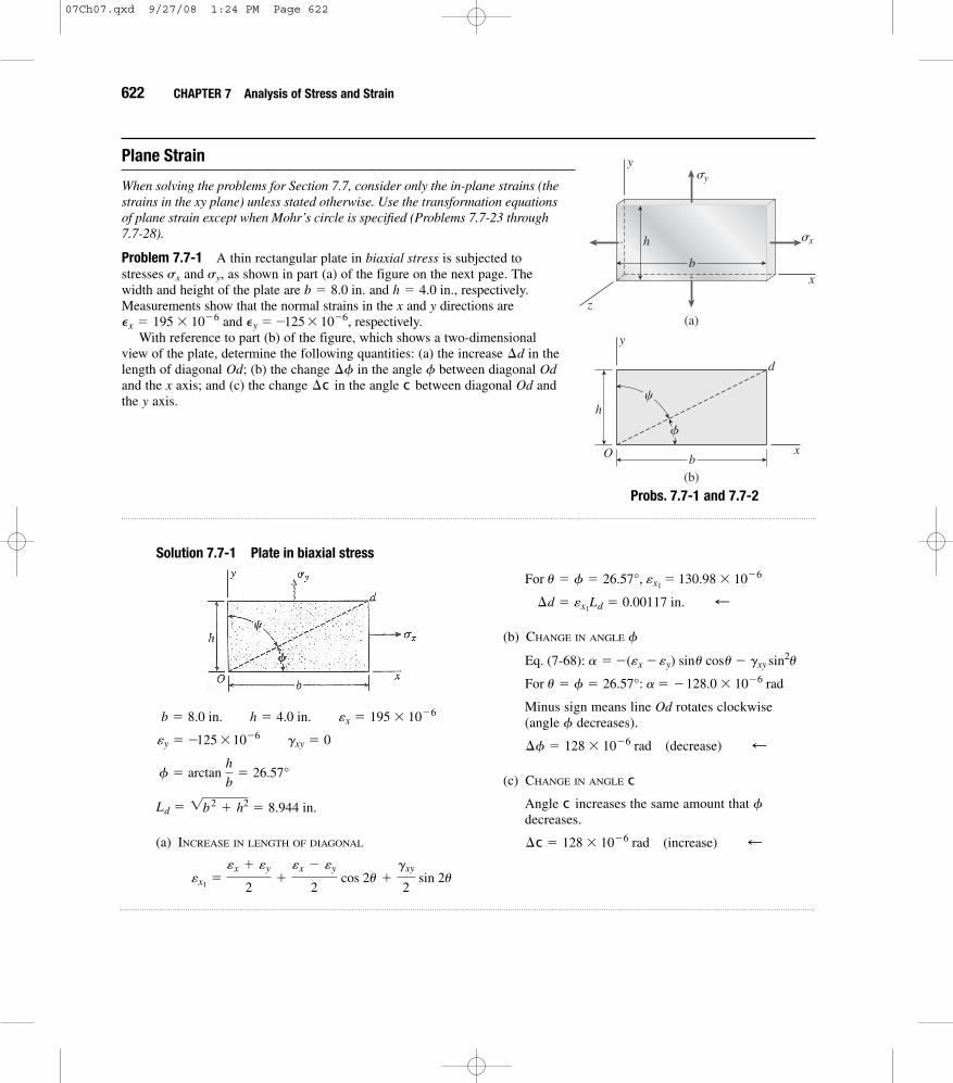
622 CHAPTER 7 Analysis of Stress and Strain
Plane Strain
When solving the problems for Section 7.7, consider only the in-plane strains (thestrains in the xy plane) unless stated otherwise. Use the transformation equationsof plane strain except when Mohr’s circle is specified (Problems 7.7-23 through7.7-28).
Problem 7.7-1 A thin rectangular plate in is subjected tostresses sx and sy, as shown in part (a) of the figure on the next page. Thewidth and height of the plate are and , respectively.Measurements show that the normal strains in the and directions are
and , respectively. With reference to part (b) of the figure, which shows a two-dimensional
view of the plate, determine the following quantities: (a) the increase in thelength of diagonal ; (b) the change in the angle between diagonal and the axis; and (c) the change in the angle between diagonal andthe axis.y
Odc¢cxOdf¢fOd
¢d
Py � �125 * 10�6Px � 195 * 10�6
yxh � 4.0 in.b � 8.0 in.
biaxial stress
sy
sx
y
b
h
xO
(a)
y
x
z
b
h
(b)
f
c
d
Solution 7.7-1 Plate in biaxial stress
(a) INCREASE IN LENGTH OF DIAGONAL
âx1�
âx + ây
2+
âx � ây
2 cos 2u +
gxy
2 sin 2u
Ld � 1b2+ h2 � 8.944 in.
f � arctan h
b� 26.57°
ây � �125 * 10�6 gxy � 0
b � 8.0 in. h � 4.0 in. âx � 195 * 10�6
(b) CHANGE IN ANGLE
Minus sign means line rotates clockwise (angle decreases).
(c) CHANGE IN ANGLE
Angle increases the same amount that decreases.
¢c � 128 * 10�6 rad (increase) ;
fcc
¢f � 128 * 10�6 rad (decrease) ;f
Od
For u � f � 26.57°: a � �128.0 * 10�6 rad
Eq. (7-68): a � �(âx � ây) sinu cosu � gxy sin2u
f
¢d � âx1Ld � 0.00117 in. ;
For u � f � 26.57°, âx1� 130.98 * 10�6
Probs. 7.7-1 and 7.7-2
07Ch07.qxd 9/27/08 1:24 PM Page 622

Solution 7.7-2 Plate in biaxial stress
(a) INCREASE IN LENGTH OF DIAGONAL
âx1�
âx + ây
2+
âx � ây
2 cos 2u +
gxy
2 sin 2u
Ld � 1b2+ h2 � 170.88 mm
f � arctan h
b� 20.56°
ây � �320 * 10�6 gxy � 0
b � 160 mm h � 60 mm âx � 410 * 10�6
(b) CHANGE IN ANGLE
Minus sign means line rotates clockwise (angle decreases.)
(c) CHANGE IN ANGLE
Angle increases the same amount that decreases.
¢c � 240 * 10�6 rad (increase) ;
fcc
¢f � 240 * 10�6 rad (decrease) ;
fOd
For u � f � 20.56°: a � �240.0 * 10�6 rad
Eq. (7-68): a � �(âx�ây) sin u cos u �gxy sin2u
f
¢d � âx1Ld � 0.0547 mm ;
For u � f � 20.56°: âx1 � 319.97 * 10�6
Problem 7.7-3 A thin square plate in is subjected to stresses and , as shown in part (a) of the figure . The width of the plate is Measurements show that thenormal strains in the and directions are and , respectively.
With reference to part (b) of the figure, which shows atwo-dimensional view of the plate, determine the followingquantities: (a) the increase in the length of diagonal ;(b) the change in the angle between diagonal andthe axis; and (c) the shear strain associated with diagonals
and (that is, find the decrease in angle ).cedcfOdgx
Odf¢f
Od¢d
Py � 113 * 10�6Px � 427 * 10�6yx
b � 12.0 in.sysx
biaxial stresssy
sx
y
b
b
xO
(a)
y
x
z b
b e
c d
f
(b)
f
Problem 7.7-2 Solve the preceding problem if , and Py � �320 * 10�6.b � 160 mm, h � 60 mm, Px � 410 * 10�6
SECTION 7.7 Plane Strain 623
PROBS. 7.7-3 and 7.7-4
07Ch07.qxd 9/27/08 1:24 PM Page 623

624 CHAPTER 7 Analysis of Stress and Strain
Solution 7.7-3 Square plate in biaxial stress
(a) INCREASE IN LENGTH OF DIAGONAL
¢d � âx1Ld � 0.00458 in. ;
For u � f � 45°: âx1� 270 * 10�6
âx1�
âx + ây
2+
âx � ây
2 cos 2u +
gxy
2 sin 2u
Ld � b12 � 16.97 in.
f � 45° gxy � 0
ây � 113 * 10�6
b � 12.0 in. âx � 427 * 10�6
(b) CHANGE IN ANGLE
Minus sign means line rotates clockwise (angle decreases.)
(c) SHEAR STRAIN BETWEEN DIAGONALS
(Negative strain means angle increases)
g � �314 * 10�6 rad ;ced
For u � f � 45°: gx1y1� �314 * 10�6 rad
Eq. (7-71b): gx1y1
2� �
âx �ây
2 sin 2u +
gxy
2 cos 2u
¢f � 157 * 10�6 rad (decrease) ;
fOd
For u � f � 45°: a � �157 * 10�6 rad
Eq. (7-68): a � �(âx � ây) sinu cosu � gxy sin2u
f
Problem 7.7-4 Solve the preceding problem if , and Py � 211 * 10�6.b � 225 mm, Px � 845 * 10�6
Solution 7.7-4 Square plate in biaxial stress
Ld � b12 � 318.2 mm
ây � 211 * 10�6 f � 45° gxy � 0
b � 225 mm âx � 845 * 10�6
(a) INCREASE IN LENGTH OF DIAGONAL
(b) CHANGE IN ANGLE
Minus sign means line rotates clockwise (angle decreases.)
¢f � 317 * 10�6 rad (decrease) ;
fOd
For u � f � 45°: a � �317 * 10�6 rad
Eq. (7-68): a � �(âx � ây) sin u cos u � gxysin2u
f
¢d � âx1Ld � 0.168 mm ;
For u � f � 45°: âx1� 528 * 10�6
âx1�
âx + ây
2+
âx � ây
2 cos 2u +
gxy
2 sin 2u
07Ch07.qxd 9/27/08 1:24 PM Page 624

SECTION 7.7 Plane Strain 625
Solution 7.7-5 Element in plane strain
ây1� 239 * 10�6
âx1� 461 * 10�6 gx1y1
� 225 * 10�6
For u � 50°:
ây1� âx + ây � âx1
gx1y1
2� �
âx � ây
2 sin 2u +
gxy
2 cos 2u
âx1�
âx + ây
2+
âx �ây
2 cos 2u +
gxy
2 sin 2u
gxy � 180 * 10�6
âx � 220 * 10�6 ây � 480 * 10�6
Problem 7.7-6 Solve the preceding problem for the following data: , , and .u � 37.5°
gxy �310 * 10�6,Py � �170 * 10�6Px � 420 * 10�6
(c) SHEAR STRAIN BETWEEN DIAGONALS
Eq. (7- 71b): gx1y1
2� �
âx �ây
2 sin 2u +
gxy
2 cos 2u
(Negative strain means angle increases)
g � �634 * 10�6 rad ced
For u � f � 45°: gx1y1� �634 * 10�6 rad
Problem 7.7-5 An element of material subjected to (see figure) has strains as follows: , and
.Calculate the strains for an element oriented at an angle and show these
strains on a sketch of a properly oriented element.u � 50°
gxy � 180 * 10�6Px � 220 * 10�6, Py � 480 * 10�6
plane strain
ey
ex
gxy
y
xO 1
1
Probs. 7.7-5 through 7.7-10
07Ch07.qxd 9/27/08 1:24 PM Page 625

626 CHAPTER 7 Analysis of Stress and Strain
Problem 7.7-7 The strains for an element of material in (see figure) are as follows: , and
Determine the principal strains and maximum shear strains, and show these strains on sketches of properly orientedelements.
gxy � �350 * 10�6.Py � 140 * 10�6Px � 480 * 10�6, plane strain
Solution 7.7-6 Element in plane strain
ây1� �101 * 10�6
âx1� 351 * 10�6 gx1y1
� �490 * 10�6
For u � 37.5°:
ây1� âx + ây � âx1
gx1y1
2� �
âx � ây
2 sin 2u +
gxy
2 cos 2u
âx1�
âx + ây
2+
âx � ây
2 cos 2u +
gxy
2 sin 2u
gxy � 310 * 10�6
âx � 420 * 10�6 ây � �170 * 10�6
Solution 7.7-7 Element in plane strain
PRINCIPAL STRAINS
up2� 67.1° â2 � 66 * 10�6 ;
‹ up1� �22.9° â1 � 554 * 10�6 ;� 554 * 10�6
âx1�
âx + ây
2+
âx � ây
2 cos 2u +
gxy
2 sin 2u
For up � �22.9°:
up � �22.9° and 67.1°
2up � �45.8° and 134.2°
tan 2up �gxy
âx � ây� �1.0294
â1 � 554 * 10�6 â2 � 66 * 10�6
� 310 * 10�6; 244 * 10�6
â1, 2 �âx + ây
2; A a
âx � ây
2b2
+ agxy
2b2
gxy � �350 * 10�6
âx � 480 * 10�6 ây � 140 * 10�6
MAXIMUM SHEAR STRAINS
âaver �âx + ây
2� 310 * 10�6
gmin � �488 * 10�6 ;us2
� us1+ 90° � 22.1°
gmax � 488 * 10�6 ;us1
� up1� 45° � �67.9° or 112.1°
gmax � 488 * 10�6
� 244 * 10�6
gmax
2� A a
âx �ây
2b2
+ agxy
2b2
07Ch07.qxd 9/27/08 1:24 PM Page 626

SECTION 7.7 Plane Strain 627
Problem 7.7-8 Solve the preceding problem for the following strains: , , and.gxy � �360 * 10�6
Py � �450 * 10�6Px � 120 * 10�6
Solution 7.7-8 Element in plane strain
PRINCIPAL STRAINS
â2 � �502 * 10�6 ;up2� 73.9°
‹ up1� 163.9° â1 � 172 * 10�6 ;� 172 * 10�6
âx1�
âx + ây
2+
âx � ây
2 cos 2u +
gxy
2 sin 2u
For up � 163.9°:
up � 163.9° and 73.9°
2up � 327.7° and 147.7°
tan 2up �gxy
âx � ây� �0.6316
â1 � 172 * 10�6 â2 � �502 * 10�6
� �165 * 10�6; 377 * 10�6
â1,2 �âx + ây
2; A a
âx � ây
2b2
+ agxy
2b2
gxy � �360 * 10�6
âx � 120 * 10�6 ây � �450 * 10�6 MAXIMUM SHEAR STRAINS
âaver �âx + ây
2� �165 * 10�6
gmin � �674 * 10�6 ;us2
� us1� 90° � 28.9°
gmax � 674 * 10�6 ;us1
� up1� 45° � 118.9°
gmax � 674 * 10�6
� 337 * 10�6
gmax
2� A a
âx � ây
2b2
+ agxy
2b2
07Ch07.qxd 9/27/08 1:24 PM Page 627

628 CHAPTER 7 Analysis of Stress and Strain
Problem 7.7-9 A element of material in (see figure) is subjected to strains ,and
Determine the following quantities: (a) the strains for an element oriented at an angle , (b) the principal strains,and (c) the maximum shear strains. Show the results on sketches of properly oriented element.
u � 75°gxy � 420 * 10�6.
Px � 480 * 10�6, Py � 70 * 10�6plane strain
Solution 7.7-9 Element in plane strain
ây1� 348 * 10�6
âx1� 202 * 10�6 gx1y1
� �569 * 10�6
For u � 75°:
ây1� âx + ây � âx1
gx1y1
2� �
âx � ây
2 sin 2u +
gxy
2 cos 2u
âx1�
âx + ây
2+
âx �ây
2 cos 2u +
gxy
2 sin 2u
gxy � 420 * 10�6
âx � 480 * 10�6 ây � 70 * 10�6
up2� 112.8° â2 � �18 * 10�6 ;
â1 � 568 * 10�6 ;‹ up1� 22.8°
� 568 * 10�6
âx1�
âx + ây
2+
âx � ây
2 cos 2u +
gxy
2 sin 2u
For up � 22.85°:
PRINCIPAL STRAINS
up � 22.85° and 112.85°
2up � 45.69° and 225.69°
tan 2up �gxy
âx � ây�1.0244
â1 � 568 * 10�6 â2 � �18 * 10�6
� 275 * 10�6; 293 * 10�6
â1,2 �âx + ây
2; A a
âx � ây
2b2
+ agxy
2b2
MAXIMUM SHEAR STRAINS
âaver �âx + ây
2� 275 * 10�6
gmin � �587 * 10�6 ;us2
� us1+ 90° � 67.8°
gmax � 587 * 10�6 ;us1
� up1� 45° � �22.2° or 157.8°
gmax � 587 * 10�6
gmax
2� A a
âx � ây
2b2
+ agxy
2b2
� 293 * 10�6
07Ch07.qxd 9/27/08 1:24 PM Page 628

SECTION 7.7 Plane Strain 629
Problem 7.7-10 Solve the preceding problem for the following data: , ,, and .u � 45°gxy � 780 * 10�6
Py � �430 * 10�6Px � �1120 * 10�6
Solution 7.7-10 Element in plane strain
ây1� �1165 * 10�6
âx1� �385 * 10�6 gx1y1
� 690 * 10�6
For u � 45°:
ây1� âx + ây � âx1
gx1y1
2� �
âx � ây
2 sin 2u +
gxy
2 cos 2u
âx1�
âx + ây
2+
âx � ây
2 cos 2u +
gxy
2 sin 2u
gxy � 780 * 10�6
âx � �1120 * 10�6 ây � �430 * 10�6
up2� 155.7° â2 � �1296 * 10�6 ;
‹ up1� 65.7° â1 � �254 * 10�6 ;
PRINCIPAL STRAINS
� �254 * 10�6
âx1�
âx + ây
2+
âx � ây
2 cos 2u +
gxy
2 sin 2u
For up � 65.7°:
up � 65.7° and 155.7°
2up � 131.5° and 311.5°
tan 2up �gxy
âx � ây� �1.1304
â1 � �254 * 10�6 â2 � �1296 * 10�6
� �775 * 10�6; 521 * 10�6
â1, 2 �âx + ây
2; A a
âx � ây
2b2
+ agxy
2b2
MAXIMUM SHEAR STRAINS
âaver �âx + ây
2� �775 * 10�6
gmin � �1041 * 10�6 ;us2
� us1+ 90° � 110.7°
gmax � 1041 * 10�6 ;us1
� up1� 45° � 20.7°
gmax � 1041 * 10�6
� 521 * 10�6
gmax
2� A a
âx � ây
2b2
+ agxy
2b2
07Ch07.qxd 9/27/08 1:24 PM Page 629

630 CHAPTER 7 Analysis of Stress and Strain
Solution 7.7-11 Steel plate in biaxial stress
UNITS: All stresses in psi.
STRAIN IN BIAXIAL STRESS (EQS. 7-39)
(1)
(2)
(3)
STRAINS AT ANGLE (EQ. 7-71a)
(4)Solve for sy: sy � 2400 psi
(23,400�1.3sy) cos 60°+ a1
2b a 1
30 * 106b
407 * 10�6 � a1
2b a 1
30 * 106b (12,600 + 0.7sy)
âx1�
âx + ây
2+
âx � ây
2 cos 2u +
gxy
2 sin 2u
f � 30°
âz � ��
E (sx�sy) � �
0.3
30 * 106 (18,000�sy)
ây �1
E (sy � �sx ) �
1
30 * 106 (sy � 5400)
âx �1
E (sx � �sy) �
1
30 * 106 (18,000 � 0.3sy)
Strain gage: f � 30° â � 407 * 10�6
E � 30 * 106 psi � � 0.30
sx � 18,000 psi gxy � 0 sy � ? MAXIMUM IN-PLANE SHEAR STRESS
STRAINS FROM EQS. (1), (2), AND (3)
MAXIMUM SHEAR STRAINS (EQ. 7-75)
� 104 * 10�6 ;gyz � 0 (gmax)yz
yz plane: (gmax) yz
2� A a
ây � âz
2b2
+ agyz
2b2
� 780 * 10�6 ;gxz � 0 (gmax) xz
xz plane: (gmax)xz
2� A a
âx � âz
2b2
+ agxz
2b2
� 676 * 10�6 ;gxy � 0 (gmax) xy
xy plane: (gmax) xy
2� A a
âx � ây
2b2
+ agxy
2b2
âz � �204 * 10�6
âx � 576 * 10�6 ây � �100 * 10�6
(tmax)xy �sx � sy
2� 7800 psi ;
Problem 7.7-11 A steel plate with modulus of elasticity and Poisson’s ratio is loaded in by normal stresses and (see figure). A strain gage is bonded to the plate at an angle .
If the stress is 18,000 psi and the strain measured by the gage is ,what is the maximum in-plane shear stress and shear strain ? What is themaximum shear strain in the plane? What is the maximum shear strain in the plane?yz(gmax)yz
xz(gmax)xz
(gmax)xy(tmax)xy
P � 407 * 10�6sx
f � 30°sysxbiaxial stress� � 0.30
E � 30 * 106 psi
sy
sx
y
x
z
f
Probs. 7.7-11 and 7.7-12
07Ch07.qxd 9/27/08 1:24 PM Page 630

SECTION 7.7 Plane Strain 631
Problem 7.7-12 Solve the preceding problem if the plate is made of aluminum with and , the stressis , the angle is , and the strain is 946 * 10�6.P21°f86.4 MPasx
� � 1/3E � 72 GPa
Solution 7.7-12 Aluminum plate in biaxial stress
UNITS: All stresses in MPa.
STRAIN IN BIAXIAL STRESS (EQS. 7-39)
(1)
(2)
(3)
STRAINS AT ANGLE (EQ. 7-71a)
Solve for sy: sy � 21.55 MPa (4)
+ a1
2b a 1
72,000b a115.2 �
4
3 syb
cos 42°
946 * 10�6 � a1
2b a 1
72,000b a57.6 +
2
3 syb
âx1�
âx + ây
2+
âx � ây
2 cos 2u +
gxy
2 sin 2u
f � 21°
âz � ��
E (sx�sy) � �
1/3
72,000 (86.4�sy)
ây �1
E (sy � �sx) �
1
72,000 (sy � 28.8)
âx �1
E (sx � �sy) �
1
72,000 (86.4 �
1
3 sy)
Strain gage: f � 21° â � 946 * 10�6
� � 1/3E � 72 GPa
sx � 86.4 MPa gxy � 0 sy � ? MAXIMUM IN-PLANE SHEAR STRESS
STRAINS FROM EQS. (1), (2), AND (3)
MAXIMUM SHEAR STRAINS (EQ. 7-75)
� 399 * 10�6 ;gyz � 0 (gmax)yz
yz plane: (gmax) yz
2� A a
ây � âz
2b2
+ agyz
2b2
� 1600 * 10�6 ;gxz � 0 (gmax) xz
xz plane: (gmax)xz
2� A a
âx � âz
2b2
+ agxz
2b2
� 1200 * 10�6 ;gxy � 0 (gmax) xy
xy plane: (gmax) xy
2� A a
âx � ây
2b2
+ agxy
2b2
âz � �500 * 10�6
âx � 1100 * 10�6 ây � �101 * 10�6
(tmax)xy �sx � sy
2� 32.4 MPa ;
07Ch07.qxd 9/27/08 1:24 PM Page 631

632 CHAPTER 7 Analysis of Stress and Strain
Problem 7.7-13 An element in plane stress is subjected to stresses sx � �8400 psi, sy � 1100 psi, and txy � �1700 psi (see figure). The material is aluminum with modulusof elasticity E � 10,000 ksi and Poisson’s ratio .
Determine the following quantities: (a) the strains for an element oriented at an angle, (b) the principal strains, and (c) the maximum shear strains. Show the results on
sketches of properly oriented elements.
Probs. 7.7-13 and 7.7-14
u � 30°
� � 0.33y
xO
txy
sy
sx
Solution 7.7-13 Element in plane strain
HOOKE’S LAW (EQS. 7-34 AND 7-35)
FOR
ây1� âx + ây � âx1
� 267 * 10�6
gx1y1� 868 * 10�6
� 434 * 10�6
gx1y1
2� �
âx � ây
2 sin 2u +
gxy
2 cos 2u
� �756 * 10�6
âx1�
âx + ây
2+
âx � ây
2 cos 2u +
gxy
2 sin 2u
u � 30°:
gxy �txy
G�
2txy(1 + �)
E� �452.2 * 10�6
ây �1
E(sy � �sx) � 387.2 * 10�6
âx �1
E(sx � �sy) � �876.3 * 10�6
txy � �1700 psi E � 10,000 ksi � � 0.33
sx � �8400 psi sy � 1100 psi PRINCIPAL STRAINS
FOR
;up2� 9.8° â2 � �916 * 10�6
;‹ up1� 99.8° â1 � 426 * 10�6
� �916 * 10�6
âx1�
âx + ây
2+
âx � ây
2 cos 2u +
gxy
2 sin 2u
up � 9.8°:
up � 9.8° and 99.8°
2up � 19.7° and 199.7°
tan 2up �gxy
âx � ây� 0.3579
â1 � 426 * 10�6 â2 � �961 * 10�6
� �245 * 10�6; 671 * 10�6
â1,2 �âx + ây
2; A a
âx � ây
2b2
+ agxy
2b2
07Ch07.qxd 9/27/08 1:24 PM Page 632

SECTION 7.7 Plane Strain 633
Problem 7.7-14 Solve the preceding problem for the following data: sx � �150 MPa, sy � �210 MPa, txy � �16 MPa, and . The material is brass with and .� � 0.34E � 100 GPau � 50°
MAXIMUM SHEAR STRAINS
âaver �âx + ây
2� �245 * 10�6
;gmin � �1342 * 10�6
us2� us1
+ 90° � 144.8°
;gmax � 1342 * 10�6
us1� up1
� 45° � 54.8°
gmax � 1342 * 10�6
� 671 * 10�6
gmax
2� A a
âx � ây
2b2
+ agxy
2b2
Solution 7.7-14 Element in plane strain
HOOKE’S LAW (EQS. 7-34 AND 7-35)
FOR
ây1� âx + ây � âx1
� �907 * 10�6
gx1y1� �717 * 10�6
� �358.5 * 10�6
gx1y1
2� �
âx � ây
2 sin 2u +
gxy
2 cos 2u
� �1469 * 10�6
âx1�
âx + ây
2+
âx � ây
2 cos 2u +
gxy
2 sin 2u
u � 50°:
gxy �txy
G�
2txy(1 + �)
E� �429 * 10�6
ây �1
E(sy � �sx) � �1590 * 10�6
âx �1
E(sx � �sy) � �786 * 10�6
txy � �16 MPa E � 100 GPa � � 0.34
sx � �150 MPa sy � �210 MPa
PRINCIPAL STRAINS
up � 76.0° and 166.0°
2up � 151.9° and 331.9°
tan 2up �gxy
âx � ây� �0.5333
â1 � �732 * 10�6 â2 � �1644 * 10�6
� �1188 * 10�6; 456 * 10�6
â1,2 �âx + ây
2; A a
âx � ây
2b2
+ agxy
2b2
07Ch07.qxd 9/27/08 1:24 PM Page 633

634 CHAPTER 7 Analysis of Stress and Strain
Problem 7.7-15 During a test of an airplane wing, the strain gage readings from a rosette (see figure) are as follows: gage , ; gage , ; and gage , .
Determine the principal strains and maximum shear strains, and show them on sketches ofproperly oriented elements.
Probs. 7.7-15 and 7.7-16
� 80 * 10�6C360 * 10�6B520 * 10�6A45°
FOR
;up2� 76.0° â2 � �1644 * 10�6
; ‹ up1� 166.0° â1 � �732 * 10�6
� �1644 * 10�6
âx1�
âx + ây
2+
âx � ây
2 cos 2u +
gxy
2 sin 2u
up � 76.0°: MAXIMUM SHEAR STRAINS
âaver �âx + ây
2� �1190 * 10�6
;gmin � �911 * 10�6
us2� us1
� 90° � 31.0°
;gmax � 911 * 10�6
us1� up1
� 45° � 121.0°
gmax � 911 * 10�6
� 456 * 10�6
gmax
2� A a
âx � ây
2b2
+ agxy
2b2
y
CB
A xO
45°
45°
07Ch07.qxd 9/27/08 1:24 PM Page 634

SECTION 7.7 Plane Strain 635
Problem 7.7-16 A strain rosette (see figure) mounted on the surface of an automobile frame gives the following readings: gage , ; gage , ; and gage , .
Determine the principal strains and maximum shear strains, and show them on sketches of properly oriented elements.�160 * 10�6C180 * 10�6B310 * 10�6A
45°
Solution 7.7-15 strain rosette 45°
FROM EQS. (7-77) AND (7-78) OF EXAMPLE 7-8:
PRINCIPAL STRAINS
â1 � 551 * 10�6 â2 � �111 * 10�6
� 220 * 10�6; 331 * 10�6
â1,2 �âx + ây
2; A a
âx � ây
2b2
+ agxy
2b2
gxy � 2âB � âA � âC � 280 * 10�6
âx � âA � 520 * 10�6 ây � âC � �80 * 10�6
âC � �80 * 10�6
âA � 520 * 10�6 âB � 360 * 10�6
MAXIMUM SHEAR STRAINS
âaver �âx + ây
2� 220 * 10�6
;gmin � �662 * 10�6
us2� us1
+ 90° � 57.5°
;gmax � 662 * 10�6
us1� up1
� 45° � �32.5°or 147.5°
gmax � 662 * 10�6
� 331 * 10�6
gmax
2� A a
âx � ây
2b2
+ agxy
2b2
;up2� 102.5° â2 � �111 * 10�6
;‹ up1� 12.5° â1 � 551 * 10�6
For
� 551 * 10�6
âx1�
âx + ây
2+
âx � ây
2 cos 2u +
gxy
2 sin 2u
up � 12.5°:
up � 12.5° and 102.5°
2up � 25.0° and 205.0°
tan 2up �gxy
âx � ây� 0.4667
07Ch07.qxd 9/27/08 1:24 PM Page 635

636 CHAPTER 7 Analysis of Stress and Strain
Solution 7.7-16 strain rosette 45°
FROM EQS. (7-77) AND (7-78) OF EXAMPLE 7-8:
PRINCIPAL STRAINS
FOR
;up2 � 102.0° â2 � �182 * 10�6
;‹ up1 � 12.0° â1 � 332 * 10�6
� 332 * 10�6
âx1�
âx + ây
2+
âx � ây
2 cos 2u +
gxy
2 sin 2u
up � 12.0°:
up � 12.0° and 102.0°
2up � 24.1° and 204.1°
tan 2up �gxy
âx � ây� 0.4468
â1 � 332 * 10�6 â2 � �182 * 10�6
� 75 * 10�6; 257 * 10�6
â1,2 �âx + ây
2; A a
âx � ây
2b2
+ agxy
2b2
gxy � 2âB � âA � âC � 210 * 10�6
âx � âA � 310 * 10�6 ây � âC � �160 * 10�6
âC � �160 * 10�6
âA � 310 * 10�6 âB � 180 * 10�6 MAXIMUM SHEAR STRAINS
âaver �âx + ây
2� 75 * 10�6
;gmin � �515 * 10�6
us2� us1
+ 90° � 57.0°
;gmax � 515 * 10�6
us1� up1
� 45° � �33.0° or 147.0°
gmax � 515 * 10�6
� 257 * 10�6
gmax
2� A a
âx � ây
2b2
+ agxy
2b2
07Ch07.qxd 9/27/08 1:24 PM Page 636

SECTION 7.7 Plane Strain 637
Problem 7.7-17 A solid circular bar of diameter in. is subjected to an axial force and a torque (see figure). Strain gages
and mounted on the surface of the bar give readingand . The bar is made of steel
having psi and .
(a) Determine the axial force and the torque .(b) Determine the maximum shear strain and the maximum
shear stress in the bar.tmax
gmax
TP
� � 0.29E � 30 * 106Pb � �55 * 10�6
Pa � 100 * 10�6BA
TPd � 1.5 d
C
B
A
P
T
C
45∞
Solution 7.7-17 Circular bar (plane stress)
Bar is subjected to a torque and an axial force .
STRAIN GAGES
ELEMENT IN PLANE STRESS
AXIAL FORCE
SHEAR STRAIN
� �(0.1298 * 10�6)T (T � lb-in.)
gxy �txy
G�
2txy(1 + �)
E� �
32T(1 + �)
pd 3E
;âx �sx
E�
4P
pd 2E P �
pd 2Eâx
4� 5300 lb
P
âx � 100 * 10�6 ây � ��âx � �29 * 10�6
sx �P
A�
4P
pd 2 sy � 0 txy � �
16T
pd 3
At u � 45°: âB � �55 * 10�6
At u � 0°: âA � âx � 100 * 10�6
Diameter d � 1.5 in.
E � 30 * 106 psi � � 0.29
PT STRAIN AT
(1)
Substitute numerical values into Eq. (1):
Solve for :
MAXIMUM SHEAR STRAIN AND MAXIMUM SHEAR STRESS
; tmax � Ggmax � 2580 psi
; gmax � 222 * 10�6 rad
� 111 * 10�6 rad
Eq. (7-75): gmax
2� A a
âx � ây
2b2
+ agxy
2b2
gxy � �(0.1298 * 10�6)T � �180.4 * 10�6 rad
; T � 1390 lb-inT
�55 * 10�6 � 35.5 * 10�6 � (0.0649 * 10�6)T
âx1� âB � �55 * 10�6 2u � 90°
âx1�
âx + ây
2+
âx � ây
2 cos 2u +
gxy
2 sin 2u
u � 45°
07Ch07.qxd 9/27/08 1:24 PM Page 637

638 CHAPTER 7 Analysis of Stress and Strain
Problem 7.7-18 A cantilever beam of rectangular cross section (width , height ) is loaded by a force that acts at the midheight of the beam and isinclined at an angle to the vertical (see figure). Two straingages are placed at point , which also is at the midheight of the beam. Gage measures the strain in the horizontaldirection and gage measures the strain at an angle b = 60to the horizontal. The measured strains are and .
Determine the force and the angle , assuming thematerial is steel with and .� � 1/3E � 200 GPa
aPPb � �375 * 10�6
Pa � 125 * 10�6°B
AC
a
Ph � 100 mmb � 25 mm
h
bP
C
C
B
A
b
b
a
h
Solution 7.7-18 Cantilever beam (plane stress)
Beam loaded by a force acting at an angle .
Axial force
Shear force
(At the neutral axis, the bending moment produces nostresses.)
STRAIN GAGES
ELEMENT IN PLANE STRESS
âx � 125 * 10�6 ây � ��âx � �41.67 * 10�6
txy � �3V
2A� �
3P cos a
2bh
sx �F
A�
P sin a
bh sy � 0
At u � 60°: âB � �375 * 10�6
At u � 0°: âA � âx � 125 * 10�6
V � P cos a
F � P sin a
h � 100 mm
E � 200 GPa � � 1/3 b � 25 mm
aP HOOKE’S LAW
(1)
(2)
FOR :
(3)
Substitute into Eq. (3):
(4)
SOLVE EQS. (1) AND (4):
P � 125 kN ;tan a � 0.5773 a � 30° ;
or P cos a � 108,260 N
� (3.464 * 10�9)P cos a
�375 * 10�6 � 41.67 * 10�6 � 41.67 * 10�6
âx1� âB � �375 * 10�6 2u � 120°
âx1�
âx + ây
2+
âx � ây
2 cos 2u +
gxy
2 sin 2u
u � 60°
� �(8.0 * 10�9) P cos a
gxy �txy
G� �
3P cos a
2bhG� �
3(1 + �) P cos a
bhE
P sin a � bhEâx � 62,500 N
âx �sx
E�
P sin a
bhE
Problem 7.7-19 Solve the preceding problem if the cross-sectional dimensions are and , the gageangle is b = 75 , the measure strains are and , and the material is a magnesium alloywith modulus and Poisson’s ratio � � 0.35.E � 6.0 * 106 psi
Pb � �266 * 10�6Pa � 171 * 10�6°
h � 3.0 in.b � 1.0 in.
Probs. 7.7-18 and 7.7-19
07Ch07.qxd 9/27/08 1:24 PM Page 638

SECTION 7.7 Plane Strain 639
Problem 7.7-20 A strain rosette, or delta rosette, consists of threeelectrical-resistance strain gages arranged as shown in the figure. Gage measuresthe normal strain in the direction of the axis. Gages and measure thestrains and in the inclined directions shown.
Obtain the equations for the strains , and associated with the axis.xygxyPx, Py
PcPb
CBxPa
A60°
Solution 7.7-19 Cantilever beam (plane stress)
Beam loaded by a force acting at an angle .
Axial force Shear foce (At the neutral axis, the bending moment producesno stresses.)
STRAIN GAGES
ELEMENT IN PLANE STRESS
âx � 171 * 10�6 ây � ��âx � �59.85 * 10�6
txy � �3V
2A� �
3P cos a
2bh
sx �F
A�
P sin a
bh sy � 0
At u � 75°: âB � �266 * 10�6
At u � 0°: âA � âx � 171 * 10�6
V � P cos aF � P sin a
h � 3.0 in.
E � 6.0 * 106 psi � � 0.35 b � 1.0 in.
aP HOOKE’S LAW
(1)
(2)
FOR :
(3)
Substitute into Eq. (3):
(4)
SOLVE EQS. (1) AND (4):
P � 5000 lb ;tan a � 0.7813 a � 38° ;
or P cos a � 3939.8 lb
�(56.25 * 10�9)P cos a
�266 * 10�6 � 55.575 * 10�6 � 99.961 * 10�6
âx1� âB � �266 * 10�6 2u � 150°
âx1�
âx + ây
2+
âx � ây
2 cos 2u +
gxy
2 sin 2u
u � 75°
� �(225.0 * 10�9)P cos a
gxy �txy
G� �
3P cos a
2bhG� �
3(1 + v)P cos a
bhE
P sin a � bhEâx � 3078 lb
âx �sx
E�
P sin a
bhE
y
CB
A
xO
60°60°
60°
Solution 7.7-20 Delta rosette ( strain rosette)60°
STRAIN GAGES
FOR u � 0°: âx � âA ;
Gage C at u � 120° Strain � âC
Gage B at u � 60° Strain � âB
Gage A at u � 0° Strain � âA
FOR :
(1)âB �âA
4+
3ây
4+
gxy13
4
âB �âA + ây
2+
âA � ây
2 (cos 120°) +
gxy
2 (sin 120°)
âx1�
âx + ây
2+
âx � ây
2 cos 2u +
gxy
2 sin 2u
u � 60°
07Ch07.qxd 9/27/08 1:24 PM Page 639

640 CHAPTER 7 Analysis of Stress and Strain
Problem 7.7-21 On the surface of a structural component in a space vehicle, the strainsare monitored by means of three strain gages arranged as shown in the figure. During a certain maneuver, the following strains were recorded:
, and .Determine the principal strains and principal stresses in the material, which is a
magnesium alloy for which and . (Show the principal strains and principal stresses on sketches of properly oriented element.)
� � 0.35E � 6000 ksi
Pc � 200 * 10�6Pb � 200 * 10�6
Pa � 1100 * 10�6,
FOR :
(2)âC �âA
4+
3ây
4�
gxy13
4
âC �âA + ây
2+
âA � ây
2 (cos 240°)
gxy
2(sin 240°)
âx1�
âx + ây
2+
âx � ây
2 cos 2u +
gxy
2 sin 2u
u � 120° SOLVE EQS. (1) AND (2):
gxy �2
13 (âB � âC) ;
ây �1
3 (2âB + 2âC � âA) ;
y
CB
AxO
30°
Solution 7.7-21 strain rosette 30-60-90°
Magnesium alloy:
STRAIN GAGES
FOR
FOR
FOR
Solve for
PRINCIPAL STRAINS
â1 � 1550 * 10�6 â2 � �250 * 10�6
� 650 * 10�6; 900 * 10�6
â1,2 �âx + ây
2; A a
âx � ây
2b2
+ agxy
2b2
gxy: gxy � 1558.9 * 10�6
� 0.43301gxy
200 * 10�6 � 650 * 10�6+ 225 * 10�6
âx1� âC �
âx + ây
2+
âx � ây
2 cos 2u +
gxy
2 sin 2u
u � 150°:
u � 90°: ây � âB � 200 * 10�6
u � 0°: âx � âA � 1100 * 10�6
Gage C at u � 150° âC � 200 * 10�6
Gage B at u � 90° âB � 200 * 10�6
Gage A at u � 0° PA � 1100 * 10�6
E � 6000 ksi � � 0.35
FOR :
up2 � 120° â2 � �250 * 10�6 ; ‹ up1 � 30° â1 � 1550 * 10�6 ;
� 1550 * 10�6
âx1�
âx + ây
2+
âx � ây
2 cos 2u +
gxy
2 sin 2u
up � 30°
2up � 60° up � 30°
tan 2up �gxy
âx � ây� 13 � 1.7321
07Ch07.qxd 9/27/08 1:24 PM Page 640

SECTION 7.7 Plane Strain 641
PRINCIPAL STRESSES (see Eqs. 7-36)
Substitute numerical values:
s1 � 10,000 psi s2 � 2,000 psi ;
s1 �E
1 � �2 (â1 + �â2) s2 �
E
1 � �2 (â2 + �â1)
Problem 7.7-22 The strains on the surface of an experimental device made of pure aluminum ( , ) and tested in a space shuttle were measured by means of strain gages. The gages were oriented as shown in the figure, and the measured strains were , , and .
What is the stress in the x direction?sx
Pc � �39.44 * 10 *�6
Pb � 1496 * 10�6Pa � 1100 * 10�6
� � 0.33E � 70 Gpa
y
CB
AxO 40°40°
Solution 7.7-22 strain rosette 40-40-100°
Pure aluminum:
STRAIN GAGES
FOR
FOR :
(1)0.41318ây + 0.49240gxy � 850.49 * 10�6
âx � 1100 * 10�6; then simplify and rearrange:
Substitute âx1� âB � 1496 * 10�6 and
âx1�
âx + ây
2+
âx � ây
2 cos 2u +
gxy
2 sin 2u
u � 40°
u � 0°: âx � âA � 1100 * 10�6
Gage C at u � 140° âC � �39.44 * 10�6
Gage B at u � 40° âB � 1496 * 10�6
Gage A at u � 0° âA � 1100 * 10�6
E � 70 GPa � � 0.33 FOR
(2)
SOLVE EQS. (1) AND (2):
HOOKE’S LAW
sx �E
1 � �2 (âx + �ây) � 91.6 MPa ;
ây � 200.3 * 10�6 gxy � 1559.2 * 10�6
0.41318ây � 0.49240gxy � �684.95 * 10�6
âx � 1100 * 10�6; then simplify and rearrange:
Substitute âx1� âc � �39.44 * 10�6 and
âx1�
âx + ây
2+
âx � ây
2 cos 2u +
gxy
2 sin 2u
u � 140°:
07Ch07.qxd 9/27/08 1:24 PM Page 641

642 CHAPTER 7 Analysis of Stress and Strain
Problem 7.7-23 Solve Problem 7.7-5 by using Mohr’s circle for plane strain.
Solution 7.7-23 Element in plane strain
POINT C:
POINT D
POINT D
gx1y1� �225 * 10�6
gx1y1
2� �R sin b � �112.4 * 10�6
âx1� 350 * 10�6 � R cos b � 239 * 10�6
(u � 140°):¿
gx1y1� 225 * 10�6
gx1y1
2� R sin b � 112.4 * 10�6
âx1� 350 * 10�6
+ R cos b � 461 * 10�6
(u � 50°):
âx1� 350 * 10�6
b � 180° � a � 2u � 45.30°
a � arctan 90
130� 34.70°
� 158.11 * 10�6
R � 2(130 * 10�6)2+ (90 * 10�6)2
gxy � 180 * 10�6 gxy
2� 90 * 10�6 u � 50°
âx � 220 * 10�6 ây � 480 * 10�6
07Ch07.qxd 9/27/08 1:24 PM Page 642

SECTION 7.7 Plane Strain 643
Problem 7.7-24 Solve Problem 7.7-6 by using Mohr’s circle for plane strain.
Solution 7.7-24 Element in plane strain
gxy � 310 * 10�6 gxy
2� 155 * 10�6 u � 37.5°
âx � 420 * 10�6 ây � �170 * 10�6 POINT C:
POINT D
POINT D
gx1y1� 490 * 10�6
gx1y1
2� R sin b � 244.8 * 10�6
âx1� 125 * 10�6 � R cos b � �101 * 10�6
œ (u � 127.5°):
gx1y1� �490 * 10�6
gx1y1
2� �R sin b � �244.8 * 10�6
âx1� 125 * 10�6
+ R cos b � 351 * 10�6
(u � 37.5°):
âx1� 125 * 10�6
b � 2u � a � 47.28°
a � arctan 155
295� 27.72°
� 333.24 * 10�6
R � 2(295 * 10�6)2+ (155 * 10�6)2
07Ch07.qxd 9/27/08 1:24 PM Page 643

644 CHAPTER 7 Analysis of Stress and Strain
Problem 7.7-25 Solve Problem 7.7-7 by using Mohr’s circle for plane strain.
Solution 7.7-25 Element in plane strain
gxy � �350 * 10�6 gxy
2� �175 * 10�6
âx � 480 * 10�6 ây � 140 * 10�6
MAXIMUM SHEAR STRAINS
gmin � �488 * 10�6
Point S2: âaver � 310 * 10�6
gmax � 2R � 488 * 10�6
Point S1: âaver � 310 * 10�6
2us1� 2us2
+ 180° � 224.17° us1� 112.1°
2us2� 90°�a � 44.17° us2
� 22.1°
POINT C:
PRINCIPAL STRAINS
Point P2: â2 � 310 * 10�6 � R � 66 * 10�6
Point P1: â1 � 310 * 10�6+ R � 554 * 10�6
2up1� 2up2
+ 180° � 314.2° up1� 157.1°
2up2� 180° � a � 134.2° up2
� 67.1°
âx1� 310 * 10�6
a � arctan 175
170� 45.83°
� 243.98 * 10�6
R � 2(175 * 10�6)2+ (170 * 10�6)2
07Ch07.qxd 9/27/08 1:24 PM Page 644

SECTION 7.7 Plane Strain 645
Solution 7.7-26 Element in plane strain
gxy � �360 * 10�6 gxy
2� �180 * 10�6
âx � 120 * 10�6 ây � �450 * 10�6
MAXIMUM SHEAR STRAINS
gmin � �674 * 10�6
Point S2: âaver � �165 * 10�6
gmax � 2R � 674 * 10�6
Point S1: âaver � �165 * 10�6
2us1� 2us2
+ 180° � 237.72° us1� 118.9°
2us2� 90° � a � 57.72° us2
� 28.9°
Point C:
PRINCIPAL STRAINS
Point P2: â2 � �165 * 10�6 � R � �502 * 10�6
Point P1: â1 � R � 165 * 10�6 � 172 * 10�6
2up1� 2up2
+ 180° � 327.72° up1� 163.9°
2up2� 180° � a � 147.72° up2
� 73.9°
âx1� �165 * 10�6
a � arctan 180
285� 32.28°
� 337.08 * 10�6
R � 2(285 * 10�6)2+ (180 * 10�6)2
Problem 7.7-26 Solve Problem 7.7-8 by using Mohr’s circle for plane strain.
07Ch07.qxd 9/27/08 1:24 PM Page 645
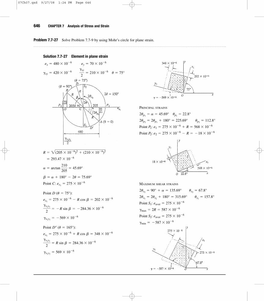
646 CHAPTER 7 Analysis of Stress and Strain
Problem 7.7-27 Solve Problem 7.7-9 by using Mohr’s circle for plane strain.
Solution 7.7-27 Element in plane strain
Point C:
Point D
Point D
gx1y1� 569 * 10�6
gx1y1
2� R sin b � 284.36 * 10�6
âx1� 275 * 10�6
+ R cos b � 348 * 10�6
œ (u � 165°):
gx1y1� �569 * 10�6
gx1y1
2� �R sin b � �284.36 * 10�6
âx1� 275 * 10�6 � R cos b � 202 * 10�6
(u � 75°):
âx1� 275 * 10�6
b � a + 180° � 2u � 75.69°
a � arctan 210
205� 45.69°
� 293.47 * 10�6
R � 2(205 * 10�6)2+ (210 * 10�6)2
gxy � 420 * 10�6 gxy
2� 210 * 10�6 u � 75°
âx � 480 * 10�6 ây � 70 * 10�6
PRINCIPAL STRAINS
Point P2: â2 � 275 * 10�6 � R � �18 * 10�6
Point P1: â1 � 275 * 10�6+ R � 568 * 10�6
2up2� 2up1
+ 180° � 225.69° up2� 112.8°
2up1� a � 45.69° up1
� 22.8°
MAXIMUM SHEAR STRAINS
gmin � �587 * 10�6
Point S2: âaver � 275 * 10�6
gmax � 2R � 587 * 10�6
Point S1: âaver � 275 * 10�6
2us1� 2us2
+ 180° � 315.69° us1� 157.8°
2us2� 90° + a � 135.69° us2
� 67.8°
07Ch07.qxd 9/27/08 1:24 PM Page 646
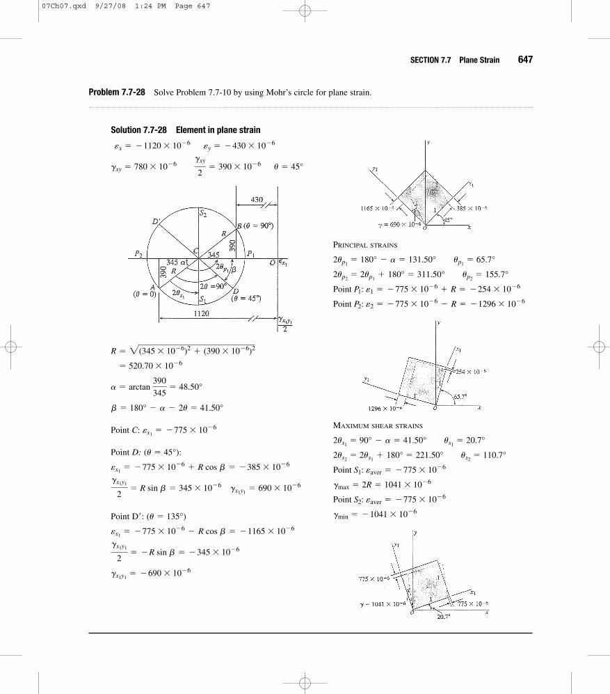
SECTION 7.7 Plane Strain 647
Problem 7.7-28 Solve Problem 7.7-10 by using Mohr’s circle for plane strain.
Solution 7.7-28 Element in plane strain
gxy � 780 * 10�6 gxy
2� 390 * 10�6 u � 45°
âx � �1120 * 10�6 ây � �430 * 10�6
PRINCIPAL STRAINS
Point P2: â2 � �775 * 10�6 � R � �1296 * 10�6
Point P1: â1 � �775 * 10�6+ R � �254 * 10�6
2up2� 2up1
+ 180° � 311.50° up2� 155.7°
2up1� 180° � a � 131.50° up1
� 65.7°
Point C:
Point D:
Point D :
gx1y1� �690 * 10�6
gx1y1
2� �R sin b � �345 * 10�6
âx1� �775 * 10�6 � R cos b � �1165 * 10�6
(u � 135°)¿
gx1y1
2� R sin b � 345 * 10�6 gx1y1
� 690 * 10�6
âx1� �775 * 10�6
+ R cos b � �385 * 10�6
(u � 45°):
âx1� �775 * 10�6
b � 180° � a � 2u � 41.50°
a � arctan 390
345� 48.50°
� 520.70 * 10�6
R � 2(345 * 10�6)2+ (390 * 10�6)2
MAXIMUM SHEAR STRAINS
gmin � �1041 * 10�6
Point S2: âaver � �775 * 10�6
gmax � 2R � 1041 * 10�6
Point S1: âaver � �775 * 10�6
2us2� 2us1
+ 180° � 221.50° us2� 110.7°
2us1� 90° � a � 41.50° us1
� 20.7°
07Ch07.qxd 9/27/08 1:24 PM Page 647

07Ch07.qxd 9/27/08 1:24 PM Page 648