chapter 7 hydrostatic uplift · pdf filechapter 7 hydrostatic uplift analysis ... design must...
TRANSCRIPT
7-1
CHAPTER 7
HYDROSTATIC UPLIFT ANALYSIS
This chapter provides information to use whenanalyzing the hydrostatic uplift potential at a wastecontainment facility in Ohio. Hydrostatic uplift mayaffect the subbase or engineered components of awaste containment facility anytime ground waterexists at a facility. When an excavation or a portionof a waste containment facility will be constructedat a depth where a phreatic surface of ground wateris present or piezometric pressures are present, thepotential adverse effects upon the wastecontainment facility will need to be taken intoaccount.
The discussion in this chapter assumes thathydrostatic uplift occurs when enough waterpressure builds to simply lift a soil layer or flexible membrane liner (FML). Although this may be a common case, other possible mechanisms of soil disruption exist under hydrostatic uplift forces. Someof them are roofing, boiling, or even a uniform heave throughout the soil mass without formation of alarge blister. The mechanism that develops is controlled mainly by soil characteristics and constructionpractices. Details on these mechanisms are given in literature and are beyond the scope of this policy.
REPORTING
This section describes the information that should besubmitted to demonstrate that a facility is notsusceptible to hydrostatic uplift. Ohio EPArecommends that the following information be includedin its own section of a geotechnical and stabilityanalyses report:
! A narrative and tabular summary of the results ofthe hydrostatic uplift analysis,
Any drawings or cross sections referred to in thispolicy that are already present in another part ofthe geotechnical and stability analyses report canbe referenced rather than duplicated in eachsection. It is helpful if the responsible partyensures the referenced items are easy to locate andmarked to show the appropriate information.
When the ground water head is sufficiently high,pressure may cause soil layers affected by the pressureto lose strength and fail. It is widely accepted that theeffective stress created by a soil mass is the mainfactor that determines the engineering behavior of thatsoil. According to Terzaghi et al, 1996, total stress insoil is a sum of an effective stress (or intergranularstress as a result of particle-to-particle contactpressure) and a neutral stress (pore water pressure). At the instance of failure, total stress in the soil isequal to the pore water pressure, and the effectivestress is equal to zero. In other words, when particle-to-particle contact disappears, so does the soil’sstrength.
Chapter 7 - Hydrostatic Uplift Analysis
7-2
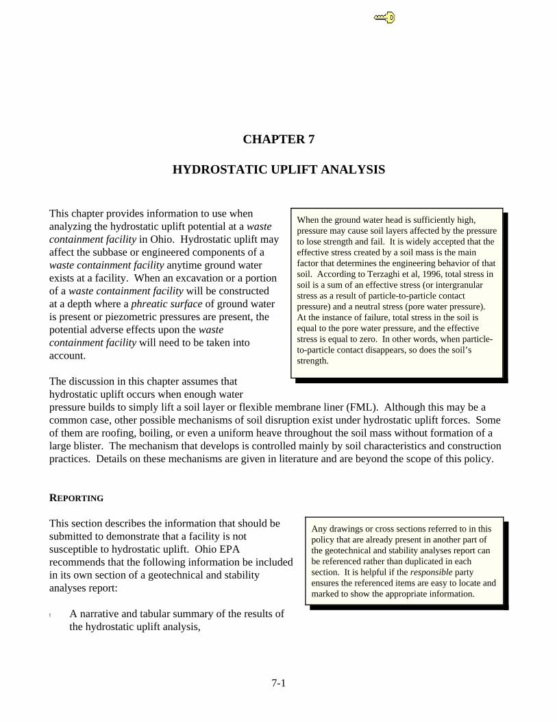
Figure 7-1 Hydrostatic pressure can cause in situ materials to fracture and allow the passageof the underlying ground water into an excavation, causing flooding of the excavation andweakening the in situ materials. Note the two delta formations in the above picture that areobvious evidence of flow through the in situ materials, which at this Ohio landfill, are over20 feet thick.
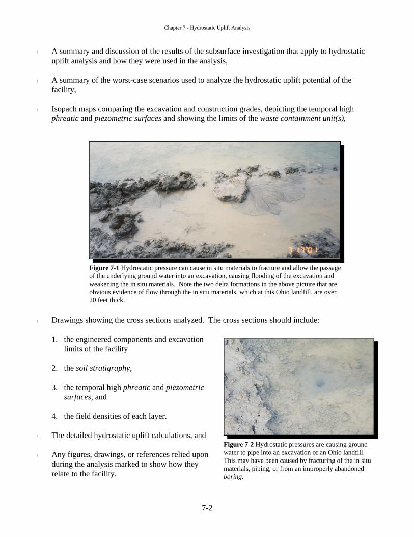
Figure 7-2 Hydrostatic pressures are causing groundwater to pipe into an excavation of an Ohio landfill. This may have been caused by fracturing of the in situmaterials, piping, or from an improperly abandonedboring.
! A summary and discussion of the results of the subsurface investigation that apply to hydrostaticuplift analysis and how they were used in the analysis,
! A summary of the worst-case scenarios used to analyze the hydrostatic uplift potential of thefacility,
! Isopach maps comparing the excavation and construction grades, depicting the temporal highphreatic and piezometric surfaces and showing the limits of the waste containment unit(s),
! Drawings showing the cross sections analyzed. The cross sections should include:
1. the engineered components and excavationlimits of the facility
2. the soil stratigraphy,
3. the temporal high phreatic and piezometricsurfaces, and
4. the field densities of each layer.
! The detailed hydrostatic uplift calculations, and
! Any figures, drawings, or references relied uponduring the analysis marked to show how theyrelate to the facility.
Chapter 7 - Hydrostatic Uplift Analysis
7-3
FACTOR OF SAFETY
The following factor of safety should be used, unless superseded by rule, when demonstrating that afacility will resist hydrostatic uplift.
Hydrostatic Uplift Analysis: FS > 1.40
The use of a higher factor of safety against hydrostaticuplift may be warranted whenever:
! A failure would have a catastrophic effect uponhuman health or the environment,
! Uncertainty exists regarding the accuracy, consistency,or validity of data, and no opportunity exists to conductadditional testing to improve or verify the quality ofthe data,
! Large uncertainty exists about the effects that changesto the site conditions over time may have on thephreatic or piezometric surfaces, and no engineeredcontrols can be implemented that will significantly reduce the uncertainty.
A facility must be designed to prevent failures due tohydrostatic uplift. A factor of safety against hydrostaticuplift lower than 1.40 is not considered a sound engineeringpractice in most circumstances. This is due to theuncertainties in calculating a factor of safety againsthydrostatic uplift, and any failure of the waste containmentfacility due to hydrostatic uplift is likely to increase thepotential for harm to human health and the environment. Ifa facility has a factor of safety against hydrostatic uplift lessthan 1.40, mitigation of the hydrostatic uplift pressures,redesigning the facility to achieve the required factor ofsafety, or using another site not at risk of a failure due tohydrostatic uplift will be necessary.
However, if unusual circumstances exist at a facility, such as the geometry of the worst-case location forhydraulic uplift is unique to one phase, it is a small portion of the phase, pumping of water out of thesaturated soil unit or bedrock can be done to alleviate hydrostatic uplift pressure, and the area can beexcavated, constructed and buried by sufficient waste or fill material during the same constructionseason so that failure of the engineered components will be prevented, then the responsible party maypropose (this does not imply approval will be granted) to use a lower factor of safety against hydrostatic uplift in the range of 1.4 to 1.2. The proposal should include any pertinent information necessary fordemonstrating the appropriateness of the lower factor of safety to the facility.
Designers may want to consider increasingthe required factor of safety if repairing afacility after a failure would create a hardshipfor the responsible parties or the wastedisposal customers.
The factors of safety specified in this policyare based on the assumptions contained inthis policy. Those assumptions include, butare not limited to, the use of conservative,site-specific, higher quality data; properselection of worst-case geometry; and the useof calculation methods that are demonstratedto be valid and appropriate for the facility. Ifdifferent assumptions are used, these factorsof safety may not be appropriately protectiveof human health and the environment.
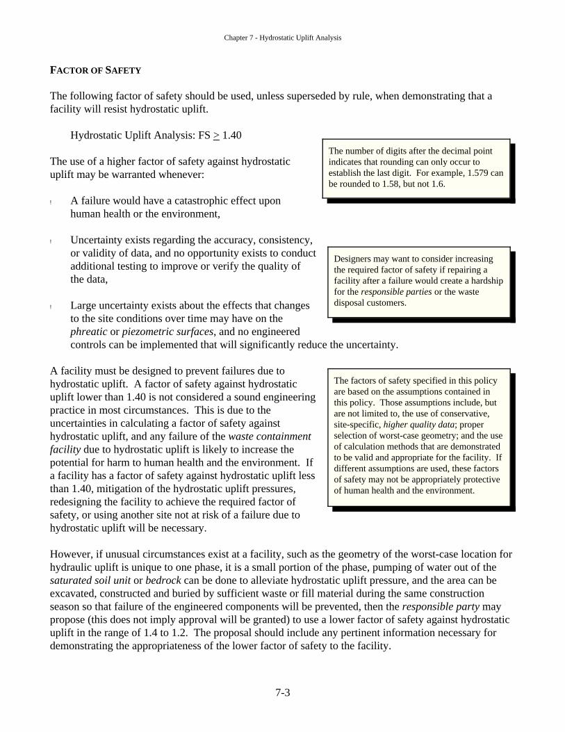
The number of digits after the decimal pointindicates that rounding can only occur toestablish the last digit. For example, 1.579 canbe rounded to 1.58, but not 1.6.
Chapter 7 - Hydrostatic Uplift Analysis
7-4
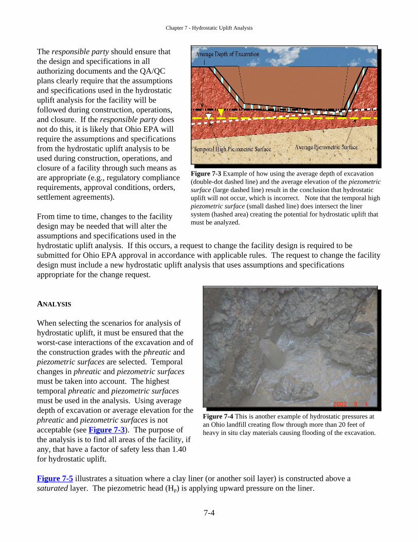
Figure 7-3 Example of how using the average depth of excavation(double-dot dashed line) and the average elevation of the piezometricsurface (large dashed line) result in the conclusion that hydrostaticuplift will not occur, which is incorrect. Note that the temporal highpiezometric surface (small dashed line) does intersect the linersystem (hashed area) creating the potential for hydrostatic uplift thatmust be analyzed.
Figure 7-4 This is another example of hydrostatic pressures atan Ohio landfill creating flow through more than 20 feet ofheavy in situ clay materials causing flooding of the excavation.
The responsible party should ensure thatthe design and specifications in allauthorizing documents and the QA/QCplans clearly require that the assumptionsand specifications used in the hydrostaticuplift analysis for the facility will befollowed during construction, operations,and closure. If the responsible party doesnot do this, it is likely that Ohio EPA willrequire the assumptions and specificationsfrom the hydrostatic uplift analysis to beused during construction, operations, andclosure of a facility through such means asare appropriate (e.g., regulatory compliancerequirements, approval conditions, orders,settlement agreements).
From time to time, changes to the facilitydesign may be needed that will alter theassumptions and specifications used in thehydrostatic uplift analysis. If this occurs, a request to change the facility design is required to besubmitted for Ohio EPA approval in accordance with applicable rules. The request to change the facilitydesign must include a new hydrostatic uplift analysis that uses assumptions and specificationsappropriate for the change request.
ANALYSIS
When selecting the scenarios for analysis ofhydrostatic uplift, it must be ensured that theworst-case interactions of the excavation and ofthe construction grades with the phreatic andpiezometric surfaces are selected. Temporalchanges in phreatic and piezometric surfacesmust be taken into account. The highesttemporal phreatic and piezometric surfacesmust be used in the analysis. Using averagedepth of excavation or average elevation for thephreatic and piezometric surfaces is not acceptable (see Figure 7-3). The purpose ofthe analysis is to find all areas of the facility, ifany, that have a factor of safety less than 1.40for hydrostatic uplift.
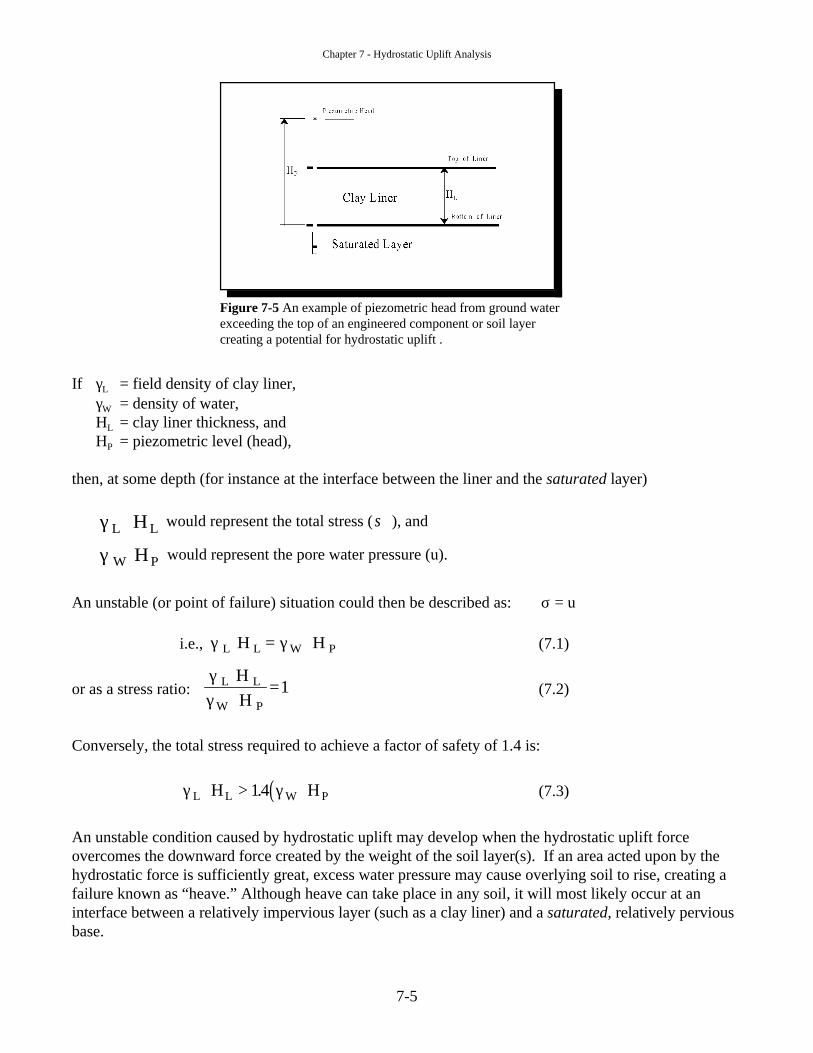
Figure 7-5 illustrates a situation where a clay liner (or another soil layer) is constructed above asaturated layer. The piezometric head (HP) is applying upward pressure on the liner.
Chapter 7 - Hydrostatic Uplift Analysis
7-5
Figure 7-5 An example of piezometric head from ground waterexceeding the top of an engineered component or soil layercreating a potential for hydrostatic uplift .
If γL = field density of clay liner,γW = density of water,HL = clay liner thickness, andHP = piezometric level (head),
then, at some depth (for instance at the interface between the liner and the saturated layer)
would represent the total stress ( ), andγ L LH⋅ σ
would represent the pore water pressure (u). γ W PH⋅
An unstable (or point of failure) situation could then be described as: σ = u
i.e., (7.1)γ γL L W PH H⋅ = ⋅
or as a stress ratio: (7.2)γγ
L L
W P
HH
⋅⋅
=1
Conversely, the total stress required to achieve a factor of safety of 1.4 is:
(7.3)( )γ γL L W PH H⋅ > ⋅14.
An unstable condition caused by hydrostatic uplift may develop when the hydrostatic uplift forceovercomes the downward force created by the weight of the soil layer(s). If an area acted upon by thehydrostatic force is sufficiently great, excess water pressure may cause overlying soil to rise, creating afailure known as “heave.” Although heave can take place in any soil, it will most likely occur at aninterface between a relatively impervious layer (such as a clay liner) and a saturated, relatively perviousbase.
Chapter 7 - Hydrostatic Uplift Analysis
7-6
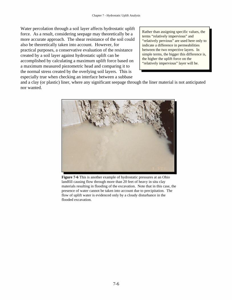
Figure 7-6 This is another example of hydrostatic pressures at an Ohiolandfill causing flow through more than 20 feet of heavy in situ claymaterials resulting in flooding of the excavation. Note that in this case, thepresence of water cannot be taken into account due to precipitation. Theflow of uplift water is evidenced only by a cloudy disturbance in theflooded excavation.
Water percolation through a soil layer affects hydrostatic upliftforce. As a result, considering seepage may theoretically be amore accurate approach. The shear resistance of the soil couldalso be theoretically taken into account. However, forpractical purposes, a conservative evaluation of the resistancecreated by a soil layer against hydrostatic uplift can beaccomplished by calculating a maximum uplift force based ona maximum measured piezometric head and comparing it tothe normal stress created by the overlying soil layers. This isespecially true when checking an interface between a subbaseand a clay (or plastic) liner, where any significant seepage through the liner material is not anticipatednor wanted.
Rather than assigning specific values, theterms “relatively impervious” and“relatively pervious” are used here only toindicate a difference in permeabilitiesbetween the two respective layers. Insimple terms, the bigger this difference is,the higher the uplift force on the“relatively impervious” layer will be.
Chapter 7 - Hydrostatic Uplift Analysis
7-7
A rough rule of thumb can bedrawn from this example, such thatpotential for heaving of a soil layerexists whenever a piezometric level(head) extends to an elevation morethan 1.3 times the thickness of thelayer that is above the plane ofpotential failure (usually thecontact plane between two layerswith different permeabilities).
Hydrostatic Uplift - Example Methodology
A factor of safety is commonly calculated as a ratio between a resisting (available or stabilizing) force anda driving (attacking or destabilizing) force. The factor of safety against hydrostatic uplift can be expressedas:
(7.4)FSFF
GL
HW= ≥ 140.
where FGL = downward force resulting from the weight of soil,FHW = hydrostatic uplift force, andFS = factor of safety against hydrostatic uplift.
The forces in Equation 7.4 can be defined as:
F H AGL L L= ⋅ ⋅γand
F H AHW w p= ⋅ ⋅γ
where A = unit area.
When the forces in Equation 7.4 are substituted with above definitions, unit areas cancel. The expressionnow takes the form of Terzaghi’s equation (Equation 7.2), with exception that number 1, previouslyindicating an unstable condition, is replaced with a FS:
(7.5)FSHH
L L
W P=
⋅⋅
≥γγ
140.
For example, if γL= 112 pcf and γW= 62.4 pcf then the critical piezometric level can be calculated by using Equation7.5 as follows:
( )HHFS
HH HP
L L
W
LL L≤
⋅⋅
≤⋅⋅
≤ ⋅ ≈ ⋅γγ
11262 4 14
1282 13. .
. .
The piezometric level in the saturated layer can be measured with piezometers, water levels in borings, orother techniques, and compared to 1.3·HL to very roughly assess the likelihood of hydrostatic uplift. However, for permit applications or other authorization requests submitted to Ohio EPA, accuratecalculations using facility specific values must be included.
Chapter 7 - Hydrostatic Uplift Analysis
7-8
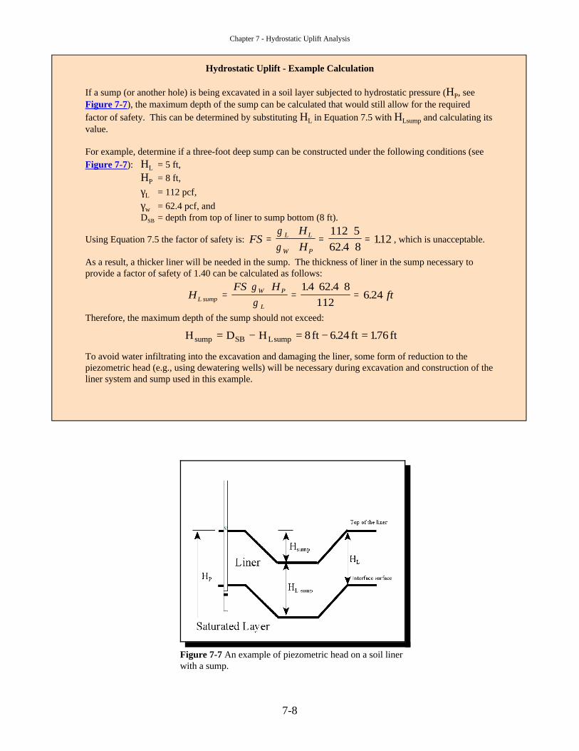
Figure 7-7 An example of piezometric head on a soil linerwith a sump.
Hydrostatic Uplift - Example Calculation
If a sump (or another hole) is being excavated in a soil layer subjected to hydrostatic pressure (HP, seeFigure 7-7), the maximum depth of the sump can be calculated that would still allow for the requiredfactor of safety. This can be determined by substituting HL in Equation 7.5 with HLsump and calculating itsvalue.
For example, determine if a three-foot deep sump can be constructed under the following conditions (seeFigure 7-7): HL = 5 ft,
HP = 8 ft,γL = 112 pcf, γw = 62.4 pcf, andDSB = depth from top of liner to sump bottom (8 ft).
Using Equation 7.5 the factor of safety is: , which is unacceptable.FSHH
L L
W P
=⋅⋅
=⋅⋅
=γγ
112 562 4 8
112.
.
As a result, a thicker liner will be needed in the sump. The thickness of liner in the sump necessary toprovide a factor of safety of 1.40 can be calculated as follows:
HFS H
ftL sumpW P
L
=⋅ ⋅
=⋅ ⋅
=γγ
14 62 4 8112
6 24. .
.
Therefore, the maximum depth of the sump should not exceed:
H D H ft ft ftsump SB Lsump= − = − =8 6 24 176. .
To avoid water infiltrating into the excavation and damaging the liner, some form of reduction to thepiezometric head (e.g., using dewatering wells) will be necessary during excavation and construction of theliner system and sump used in this example.
Chapter 7 - Hydrostatic Uplift Analysis
7-9
REFERENCES
Das, B. M., 1994, Principles of Geotechnical Engineering, 3rd ed., PWS Publishing Company, Boston,Massachusetts.
Holtz, R. D., and Kovacs, W. D., 1981, An Introduction to Geotechnical Engineering, Prentice Hall,Englewood Cliffs, New Jersey.
Sowers, G. F., 1979, Introductory Soil Mechanics and Foundations, 4th ed., Macmillan Publishing Co.,Inc., New York, New York.
Terzaghi, K., Peck, R. B. and Mesri, G., 1996, Soil Mechanics in Engineering Practice, 3rd ed., JohnWiley & Sons, Inc., New York, New York.

Chapter 7 - Hydrostatic Uplift Analysis
7-10
This page intentionally left blank.