chapter 7: instrumentation systems
TRANSCRIPT

© WJEC CBAC Ltd 2018245
GCE A level Electronics – Chapter 7: Instrumentation Systems
Chapter 7: Instrumentation systems
Learning Objectives:
At the end of this topic you will be able to:• describe the use of the following analogue sensors:
• thermistors• strain gauge
• describe the use of the following digital sensors:• slotted discs (for sensing rotational speed)• encoded discs (for sensing angular position)
• recall the Gray code (3 bit) and explain its use in encoded discs• recall the advantages of a bridge circuit compared to a simple voltage divider
circuit• recall and explain the significance of the following ideal properties of an
instrumentation amplifier:• high input impedance• high common-mode rejection ratio
• analyse and design instrumentation amplifiers based on the op-amp difference amplifier circuit
• select and use the formula:
• design a logic system to process the output of slotted and encoded discs to meet a given specification.
Analogue sensing units:
In the E-book for the AS course, the role of sensing units such as thermistors, LDR’s and phototransistors was examined. Here, the use of ntc thermistors and strain gauges in instrumentation circuits is considered.
The thermistor
In ntc thermistors, the resistance falls as temperature rises.
FOUT DIFF
1
RV V
R=

© WJEC CBAC Ltd 2018246
GCE A level Electronics – Chapter 7: Instrumentation Systems
Example
The diagram shows one form of temperature-sensing unit.
• Thermistor resistance:• 1 kΩ. at 20 0C• 3.2 kΩ at 2 0C.
• Variable resistor - set to a resistance of 2 kΩ.• Supply voltage VS = 12 V.
Calculate the output voltage VOUT at:
(a) 20 0C(b) 2 0C.
Using the voltage divider formula: VOUT = R2 VIN
R1 + R2
Using the voltage divider formula:
(a) At 20 0C VOUT = 2 12 = 8 V 1 + 2
(b) At 2 0C. VOUT = 2 12 = 4.6 V 3.2 + 2
The strain gauge
When trucks drive over a bridge, or someone standson bathroom scales, the structure is squashed slightly.Strain is defined as this change in length divided by theoriginal length and it is measured using a strain gauge. The layout of a typical strain gauge is shown opposite.It is often glued to the structure under test so that it isdistorted when the structure is distorted.This changes the resistance of the strain gauge. When a wire is stretched, it gets longer and thinner.As a result, its electrical resistance increases.By measuring the change in resistance, we can monitor the strainthat produced it.
The strain gauge could be incorporated into a voltage divider circuit, like that shown below. This behaves in a similar way to the temperature sensor, discussed earlier.

© WJEC CBAC Ltd 2018247
GCE A level Electronics – Chapter 7: Instrumentation Systems
There are problems with sensing circuits in the form of simple voltage dividers:
• The resistance of the sensor may change because of some factor other than the one you are trying to measure. For example, the resistance of a strain gauge changes if the strain gauge gets hot. This has nothing to do with any forces applied to it.
• The voltage divider formula: VOUT =
R2 VIN R1 + R2
shows that the output voltage depends on the supply voltage. In many situations, the supply voltage will fluctuate:
• the system may be battery-powered and using batteries that are going flat• the power supply cables might be subject to electrical noise, which changes the
instantaneous value of the supply voltage. In other words, a change in the output may be the result of a change in some other factor in its surroundings, rather than a change in the factor you are trying to monitor.
A bridge sensing circuit:
Both of the problems outlined above can be overcome or reduced by using a bridge circuit. A bridge circuit can be drawn in two ways, but the circuit is the same. The following diagrams show the two forms of a bridge circuit for a temperature-sensing unit:
In a bridge circuit, there are two sensing devices, each connected in its own voltage divider. Although the thermistors should be a matched pair, the variable resistor is needed to take into account the small difference in their characteristics. The variable resistor is adjusted so that VOUT is set to zero when both thermistors are at same temperature. The bridge is then said to be ‘balanced’.
The output is the voltage difference between the outputs (B and A) of the two voltage dividers.
In the case above, there are two thermistors, P and Q. One is subjected to the temperature changes under investigation. The other is not. That is the only difference. Both thermistors are equally exposed to all other environmental conditions.

© WJEC CBAC Ltd 2018248
GCE A level Electronics – Chapter 7: Instrumentation Systems
Null measurement technique:
When the bridge is ‘balanced’ and VOUT is zero: Voltage at A = voltage at BPut another way: Resistance of P = Resistance of Q
Resistance of variable resistor Resistance of R
The example below shows that, in this condition, the voltage of the power supply makes no difference at all to the output voltage. Any value can be used, but two conflicting issues need to be considered.The higher the supply voltage:
• the more sensitive the output voltage is to changes in the condition being monitored• the greater the self-heating effect of all the resistors in the circuit.
Any changes in the condition being monitored, e.g. temperature, makes the bridge unbalanced, meaning that VOUT is no longer zero. Using this null measurement makes it possible to detect very small changes in these conditions, by connecting the bridge circuit to a high gain voltage amplifier, as outlined below.
Example
A thermistor bridge circuit is connected to a 12 V power supply.
The variable resistor is adjusted until the bridge is balanced,i.e. the output VOUT = 0 V.It then has a resistance of exactly 2.5 kΩ.Thermistor Q is found to have a resistance of 1.2 kΩ.
(a) Calculate the resistance of thermistor P.(b) The power supply voltage is changed to 10 V. Calculate the new output voltage VOUT1.(c) The power supply voltage changes to 6 V. The resistance of thermistor P changes to 1.3 kΩ. Calculate the new output voltage VOUT2.
(a) The bridge is balanced, so:
Resistance of P = Resistance of Q
Resistance of variable resistor Resistance of R
Resistance of P = 1.2
2.5 2
Resistance of P = 1.2 x 2.5 = 1.5 kΩ

© WJEC CBAC Ltd 2018249
GCE A level Electronics – Chapter 7: Instrumentation Systems
(b) Using the voltage divider formula:
new voltage at A = 2.5 10 = 6.25 V 1.5 + 2.5
new voltage at B = 2.5 10 = 6.25 V 1.2 + 2
VOUT1 = voltage at B - voltage at A = 0 V.
The bridge is still balanced even though the supply voltage has changed. (c) Using the voltage divider formula:
new voltage at A = 2.5 6 = 3.95 V 1.3 + 2.5
new voltage at B = 2 6 = 3.75 V 1.2 + 2 VOUT2 = voltage at B - voltage at A = 0.20 V. The bridge is now unbalanced.
A strain gauge bridge circuit:
As in the temperature-sensing bridge circuit, there are two sensing devices, in this case labelled ‘Strain gauge’ and ‘Dummy strain gauge’. Their positions in the bridge can be reversed.The strain gauge is glued to the structure in such a way that it is distorted by movement of the structure. The dummy strain gauge is glued nearby so that it is exposed to exactly the same conditions, except for the distortion. Often, the two strain gauges are formed on the same substrate, as shown in the diagram.
Initially the variable resistor is used to balance the bridge as described earlier.

© WJEC CBAC Ltd 2018250
GCE A level Electronics – Chapter 7: Instrumentation Systems
Exercise 7.1
1. A system is required to show which thermistor, P or Q, is hotter. The two thermistors have identical temperature coefficients. They are connected in the sensing sub-system shown opposite. When P and Q are at the same temperature, VOUT is zero volts.
Calculate VOUT when:• resistance of P = 8.4 kΩ• resistance of Q = 8.7 kΩ• resistance of variable resistor = 10.3 kΩ
2. The circuit diagram shows two identical strain gauges connected to precision 100 Ωresistors in a bridge circuit.
Under test conditions, the strain gauge, S, is found to have a resistance of exactly100.5 Ω, while the dummy strain gauge, T, has a resistance of exactly 100 Ω.
(a) Calculate the voltages at points P and Q, and hence work out the voltage VDIFF, correct to three decimal places.
b) What is the purpose of the dummy strain gauge, in this circuit?
Ω
ΩΩ

© WJEC CBAC Ltd 2018251
GCE A level Electronics – Chapter 7: Instrumentation Systems
Instrumentation amplifiers:
The output from a bridge circuit is tiny, typically only a few millivolts. It is usually amplified by a high gain voltage amplifier, known as an instrumentation amplifier.
Ideal characteristics:
• High input impedance: ensures that as much as possible of the signal from the bridge circuit is transferred to the instrumentation amplifier. The current flowing between the two sub-systems is very small. The voltage dropped across the output impedance of the bridge circuit, (and so not transferred to the amplifier) is kept to a minimum.
• High common-mode rejection ratio (CMRR) (on both inputs). Part of the steady DC voltages on the outputs of the voltage dividers that make up the bridge circuit will appear on, (be common to) both amplifier inputs. A high CMRR ensures that the instrumentation amplifier ignores these, and amplifies only the difference between these signals.
The circuit diagram for a simple instrumentation amplifier is shown below.
It is based on an op-amp difference amplifier.
Resistor sizes: RA = RD (and is often called RF) RB = RC (and is often called R1)
Resistor values should not be less than 1kΩ.
With careful design, this circuit can exhibit characteristics close to the ideal for an instrumentation amplifier. (In practice, instrumentation amplifiers are more complex.)
The formula for calculating the output voltage, VOUT, can be written in two ways:
VOUT = (V+ - V- ) × RF = VDIFF ×
RF
R1 R1

© WJEC CBAC Ltd 2018252
GCE A level Electronics – Chapter 7: Instrumentation Systems
Example
Calculate the output voltage for the circuit shown below when the input voltages are set to 4V and 5 V.
Using the formula given earlier:
VOUT = VDIFF × RF (5 - 4) × 330 = 1.5 V
R1 220
(Take care to subtract the input voltages in the right order – non-inverting input voltage minus inverting input voltage.)
Ω
Ω
Ω
Ω

© WJEC CBAC Ltd 2018253
GCE A level Electronics – Chapter 7: Instrumentation Systems
Investigation 7.1
(a) Set up the following circuit on Circuit Wizard.
(b) Adjust the temperature to 20 °C.(c) Adjust the 10 kΩ variable resistor so that the reading on the voltmeter is as near to zero as possible (this will be somewhere near 6.29 kΩ). Do not make any further adjustments to the variable resistor as the bridge circuit is now balanced(d) Set the thermistor temperature to 14 °C and record the voltmeter reading in the table.
Repeat this process for the other temperatures.
(e) Use your results to draw a graph of the voltage against temperature. Comment on the effectiveness of the circuit as a thermometer and give a suitable temperature range for its use.
Temperature / 0C
Voltmeter reading / V
14 16 18 20 22 24 26

© WJEC CBAC Ltd 2018254
GCE A level Electronics – Chapter 7: Instrumentation Systems
Exercise 7.2
1. A difference amplifier controls a fan to keep the temperature constant in a pottery kiln.
Two temperature sensors provide information about the temperature at the top and the bottom of the kiln.
(a) Each temperature sensor uses a ntc thermistor and a variable resistor in a voltage divider. Draw the circuit diagram for a temperature sensor bridge circuit, designed to give an output voltage, VDIFF, that increases as the temperature increases.
(b) The circuit diagram for the difference amplifier is given opposite.
The top temperature sensor output = 2.4 V.
The bottom temperature sensor output = 2.1 V.
Calculate the output voltage VOUT of the difference amplifier.
Ω
Ω
Ω
Ω

© WJEC CBAC Ltd 2018255
GCE A level Electronics – Chapter 7: Instrumentation Systems
2. A simple strain meter contains a strain gauge S, two equal resistors, R, and a variable resistor VR connected in a bridge circuit. Its output is amplified by a difference amplifier. (a) Complete the circuit diagram for this strain meter.
(b) What is the advantage of this arrangement over a simple voltage divider and amplifier?
(c) Under certain conditions, voltage V1 is 3.003 V and voltage V2 is 3.015 V.
Determine suitable values for each of the four resistors used in the difference amplifier to provide an output voltage VOUT = 2.4 V.
Label the circuit diagram with these values.
© WJEC CBAC Ltd 2018256
GCE A level Electronics – Chapter 7: Instrumentation Systems
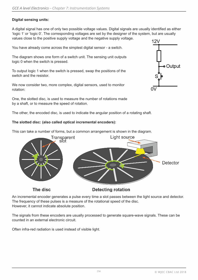
Digital sensing units:
A digital signal has one of only two possible voltage values. Digital signals are usually identified as either ‘logic 1’ or ‘logic 0’. The corresponding voltages are set by the designer of the system, but are usually values close to the positive supply voltage and the negative supply voltage.
You have already come across the simplest digital sensor - a switch.
The diagram shows one form of a switch unit. The sensing unit outputslogic 0 when the switch is pressed.
To output logic 1 when the switch is pressed, swap the positions of theswitch and the resistor.
We now consider two, more complex, digital sensors, used to monitorrotation:
One, the slotted disc, is used to measure the number of rotations madeby a shaft, or to measure the speed of rotation.
The other, the encoded disc, is used to indicate the angular position of a rotating shaft.
The slotted disc: (also called optical incremental encoders):
This can take a number of forms, but a common arrangement is shown in the diagram.
An incremental encoder generates a pulse every time a slot passes between the light source and detector. The frequency of these pulses is a measure of the rotational speed of the disc.However, it cannot indicate absolute position.
The signals from these encoders are usually processed to generate square-wave signals. These can be counted in an external electronic circuit.
Often infra-red radiation is used instead of visible light.

© WJEC CBAC Ltd 2018257
GCE A level Electronics – Chapter 7: Instrumentation Systems
The encoded disc (also called absolute encoders):
The slotted disc shown above can measure the number rotations made by the shaft and by combining that information with the time it took to do so, can measure rotational speed (angular velocity) of the shaft.
However it has two limitations:
• it cannot pinpoint its current (angular) position;• it cannot distinguish between clockwise rotation and anticlockwise rotation.
One way to overcome both of these limitations is to use an optically read, encoded disc.We consider two versions, the binary encoded disc and the Gray code encoded disc.The only difference between these is the pattern used on the disc.The following diagrams show these:

© WJEC CBAC Ltd 2018258
GCE A level Electronics – Chapter 7: Instrumentation Systems
The ‘rule’ for counting in Gray code is:
• only one bit should change at a time as you progress• change the least significant bit (A in this case,) provided that the result has not occurred before• if it has, then change the next least significant bit (B,) unless that result has occurred• in that case change the next bit, and so on.
The discs are ‘read’ by a series of reflective opto-switches.
An opto-switch consists of an infrared LED and a phototransistor combined in a single package. The phototransistor is arranged so that it can detect the infrared from the LED.
With a reflective opto-switch the infrared beam is only detected by the phototransistor if it is reflected by a white surface close to the switch.
Binary encoded discs can cause problems. An extreme case is illustrated in the diagram.The disc is rotating clockwise.
Currently, all four opto-switches are on white. Suppose that this causes an outputof ‘0000’.
Shortly, segment X will be under the opto-switches,causing a reading of ‘1111’. It is the changeover that causes the problem.
The opto-switches cannot be in a perfect line. The pattern on the disc cannot have an absolutely straight boundary between the segments. One of the opto-switches must move off the white area onto the dark area before the others. This will cause a false reading.
The following table shows a possible sequence of false readings that may occur while segment X is moving under the sensors.
Reflective opto-switch D C B A 0 0 0 0 0 1 0 0 False 0 1 0 1 False 0 1 1 1 False 1 1 1 1

© WJEC CBAC Ltd 2018259
GCE A level Electronics – Chapter 7: Instrumentation Systems
Of course, other sequences may occur instead.
Problems can arise whenever moving from onesegment of the disc to the next involves changingthe output of more than one opto-switch.
The solution is to use Gray code to encode thedisc. This is designed so that only one changetakes place in moving from one segment to thenext. This is illustrated in the diagram opposite.Study it carefully to convince yourself that, asthe disc rotates, only one bit of the outputchanges in going from one segment to the next.
As the Gray encoded disc rotates clockwise segment X will shortly be under the opto-switches,causing a reading of ‘1000’. The result is correct because only one bit (bit D in this case) can change even if the opto-switches are not in a perfect line.
The following table shows the only possible sequence of readings that can occur while segment X is moving under the sensors:
Resolution:
The resolution of these discs (i.e. the smallest angle that will result in a change in the output) depends on how many segments there are.
The discs considered above have a four bit output (fourrings, or sixteen segments.)Their resolution is 360 / 16 = 22.5 °.
To measure smaller angles, the number of bits in theoutput must increase, making processing it more complex.The diagram on the right shows an 8-bit encoded disc,with 256 segments giving a resolution of 360 / 256 = 1.41 °.
Reflective opto-switch D C B A 0 0 0 0 1 0 0 0 True

© WJEC CBAC Ltd 2018260
GCE A level Electronics – Chapter 7: Instrumentation Systems
Examples
1. The block diagram shows a system designed to monitor the rotational speed of the crankshaft in an engine.
The incremental encoder disc contains 100 transparent slots.
(a) What is the purpose of the Schmitt inverter in this system? (b) The counting system records 500 pulses in a 25 second period. What is the rotational speed of the shaft (in rpm - revolutions per minute)? (c) Assuming that the count is accurate to the nearest count, what is the accuracy of this rotational speed measurement?
(a) The finite width of the slot means that the amplitude of the detector output signal rises and falls. The Schmitt inverter converts these into square pulses, suitable for the counter.
(b) In 25 seconds, the disc rotates 500 times = 5 complete rotations
100
In 1 second, it rotates 5 times = 0.2 revolutions per second 25
In 1 minute, it rotates 60 x 0.2 times = 12 revolutions per minute Rotational speed = 12 rpm.
(c) 100 slots gives a resolution of 1
100
The accuracy at 12 rpm = 12 rpm ± 12 × 1 = 12 ± 0.12 100
The accuracy of the actual speed is between 11.88 and 12.12 rpm.
2. A machine tool control system uses an encoded disc to monitor how far a shaft has rotated.
The disc is encoded using Gray code, and is read by three reflective opto-switches, X, Y and Z.
The arrangement is shown in the diagram.
(a) What is the advantage of using Gray code instead of pure binary code in this application? (b) Design a logic system to convert the Gray code output from the opto-switches into binary numbers. (a) Using binary code can result in false readings when the opto-switches sit near or cross segment boundaries. Several bits may change state as the opto-switches move across the boundary. These changes do not occur simultaneously, giving rise to transient false readings. In Gray code, only one bit changes state from one segment to the next and so there can be no false reading.

© WJEC CBAC Ltd 2018261
GCE A level Electronics – Chapter 7: Instrumentation Systems
(b) The block diagram for the logic system and conversion table are shown below.
The Boolean expressions linking outputs, C and B and A to Gray code inputs Z, Y and X are:
C = Z
B = Y ⊕ Z
A = Z . (Y ⊕ Z) + Z . (Y ⊕ X)
The resulting logic system is shown below.
Gray code Binary number
Z Y X C B A 0 0 0 0 0 0
0 0 1 0 0 1
0 1 1 0 1 0
0 1 0 0 1 1
1 1 0 1 0 0
1 1 1 1 0 1
1 0 1 1 1 0
1 0 0 1 1 1

© WJEC CBAC Ltd 2018262
GCE A level Electronics – Chapter 7: Instrumentation Systems
Exercise 7.3
1. A Grey code encoded disc is used as part of a system to warn a 4x4 off-road enthusiast when the vehicle has tipped to a dangerous angle. As the vehicle tips, the pendulum swings, taking the opto-switches over a different segment of the encoded disc.
(a) (i) What is the difference between Grey code and binary code?
(ii) What is the disadvantage of using binary code rather than Grey code in this application?
(b) (i) What is the resolution of this system?
(ii) What would be the minimum number of bits required to give a resolution of at least 10°?
optoswitches
pendulum

© WJEC CBAC Ltd 2018263
GCE A level Electronics – Chapter 7: Instrumentation Systems
(c) The following table shows the behavior of the system. • Normally a green LED, G, lights, showing that the vehicle is safe. • The amber LED, A, indicates that the vehicle tilt is risky. • The red LED, R, comes on when it is dangerous.
Complete the following Boolean expressions to show the relationships between the outputs Z, Y and X, of the opto-switches and the LEDs:
G =
A =
R =
2. The block diagram shows a system designed to monitor the rotational speed a machine part.
The incremental encoder disc contains 40 transparent slots.
(a) The counting system records 800 pulses in a 10 second period. What is the rotational speed of the machine part in rpm?
(b) Assuming that the count is accurate to the nearest count, what is the accuracy of this rotational speed measurement?
Opto-switch output LEDs Z Y X G A R 0 0 0 0 0 1 0 0 1 0 1 0 0 1 1 1 0 0 0 1 0 1 0 0 1 1 0 1 0 0 1 1 1 1 0 0 1 0 1 0 1 0 1 0 0 0 0 1