chapter 7 sequential circuits boonchuay supmonchai integrated design application research (idar)...
TRANSCRIPT

Chapter 7Chapter 7
Sequential CircuitsSequential Circuits
Boonchuay SupmonchaiIntegrated Design Application Research (IDAR) Laboratory
August 20, 2004; Revised - July 4, 2005

2102-545 Digital ICs2102-545 Digital ICs Sequential Logic 2
B.SupmonchaiB.Supmonchai
Goals of This ChapterGoals of This Chapter Implementation techniques for
Register: latches and flipflops
Schmitt Triggers
Oscillator, pulse generators
Static versus Dynamic Realization
Clocking Strategies

2102-545 Digital ICs2102-545 Digital ICs Sequential Logic 3
B.SupmonchaiB.Supmonchai
Storage MechanismsStorage Mechanisms
Positive FeedbackPositive Feedback Charge-BasedCharge-Based
COMBINATIONALCOMBINATIONALLOGICLOGIC
InputsInputs OutputsOutputs
Next stateNext stateCurrent StateCurrent State
Q DStateState
RegisterRegister
CLOCKCLOCK
Sequential LogicSequential Logic
STATICSTATIC DYNAMICDYNAMIC

2102-545 Digital ICs2102-545 Digital ICs Sequential Logic 4
B.SupmonchaiB.Supmonchai
Static vs Dynamic StorageStatic vs Dynamic Storage Static storage
preserve state as long as the power is on
have positive feedback (regenerationregeneration) with an internal connection between the output and the input
useful when updates are infrequent (clock gating)
Dynamic storage store state on parasitic capacitors
only hold state for short periods of time (milliseconds)
require periodic refresh
usually simpler, so higher speed and lower power

2102-545 Digital ICs2102-545 Digital ICs Sequential Logic 5
B.SupmonchaiB.Supmonchai
Latches versus FlipflopsLatches versus Flipflops Latches (with Clock)
level sensitivelevel sensitive circuit that passes inputs to Q when the clock is high (or low) - transparent modetransparent mode
input sampled on the falling edge of the clock is held stable when clock is low (or high) - hold modehold mode
Flipflops (edge-triggered) edge sensitiveedge sensitive circuits that sample the inputs on a clock
transition positive edge-triggered: 0 1
negative edge-triggered: 1 0
built using latches (e.g., master-slave flipflops)

2102-545 Digital ICs2102-545 Digital ICs Sequential Logic 6
B.SupmonchaiB.Supmonchai
VVi2i2 VVo2o2VVo1o1VVi1i1
Cascaded InvertersCascaded Inverters
AA
VVi1 i1 = V= Vo2o2
VVi2
i2
= V= V
o1
o1
BB
CC
Review: The Regenerative PropertyReview: The Regenerative Property
Small deviation from bias point CC (e.g., from noise) is amplified and regenerated around the circuit loop until either point AA or BB is reached
If the gain in the transient region is larger than 1, only AA and BB are stable operation points. CC is a metastablemetastable operation point.

2102-545 Digital ICs2102-545 Digital ICs Sequential Logic 7
B.SupmonchaiB.Supmonchai
Review: Bistable CircuitsReview: Bistable Circuits
The cross-coupling of two inverters results in a bistable circuitbistable circuit (a circuit with two stable states)
Have to be able to changechange the stored value by making AA (or BB) temporarily unstable by increasing the loop gain to a value larger than 1 done by applying a trigger pulse at VVi1i1 or VVi2i2
the width of the trigger pulse need be only a little larger than the total propagation delay around the loop circuit (twice the delay of an inverter)
VVi1i1
VVi2i2

2102-545 Digital ICs2102-545 Digital ICs Sequential Logic 8
B.SupmonchaiB.Supmonchai
Review: SR LatchReview: SR Latch
SS RR QQ !Q!Q ActionAction
0 0 Q !Q memory
1 0 1 0 set
0 1 0 1 reset
1 1 0 0 disalloweddisallowed
SS
RRQQ
!Q!Q

2102-545 Digital ICs2102-545 Digital ICs Sequential Logic 9
B.SupmonchaiB.Supmonchai
Review: Clocked D LatchReview: Clocked D Latch
clockclock
D L
atch
D L
atch
QQDD
clockclock
DD
!Q!Q
clockclock
transparenttransparent mode
holdhold mode
In our courseAll latches mean clocked latchesclocked latches

2102-545 Digital ICs2102-545 Digital ICs Sequential Logic 10
B.SupmonchaiB.Supmonchai
D
Clk
Q D
Clk
Q
FlipflopFlipflop
stores data when clock rises (falls)rises (falls)
Clk
D
Q
Clk
D
Q
Latches versus Flipflops IILatches versus Flipflops II LatchLatch
stores data when clock is low (high)low (high)

2102-545 Digital ICs2102-545 Digital ICs Sequential Logic 11
B.SupmonchaiB.Supmonchai
Positive and Negative LatchesPositive and Negative Latches
InIn
OutOut
ClkClk
OutStable
OutFollow In
OutStable
OutFollow In
D Q
G
InIn OutOut
ClkClk
Positive Latch
InIn
OutOut
ClkClk
OutStable
OutFollow In
OutStable
OutFollow In
D Q
G
InIn OutOut
ClkClk
Negative Latch

2102-545 Digital ICs2102-545 Digital ICs Sequential Logic 12
B.SupmonchaiB.Supmonchai
• N latch is transparentwhen = 0 = 0
• P latch is transparent when = 1 = 1
Latch-Based DesignLatch-Based Design
N N LatchLatch
P P LatchLatch
LogicLogic
LogicLogic

2102-545 Digital ICs2102-545 Digital ICs Sequential Logic 13
B.SupmonchaiB.Supmonchai
clockclock
DD QQInIn OutOut
OutOut outputoutputstablestable
outputoutputstablestable
timetime
clockclock
InIn datadatastablestable
timetime
timetime
ttsusu ttholdhold
ttc-qc-q
Timing MetricsTiming Metrics

2102-545 Digital ICs2102-545 Digital ICs Sequential Logic 14
B.SupmonchaiB.Supmonchai
Timing DefinitionsTiming Definitions Setup time, ttsetupsetup is the time that the data inputs
(D) must be valid before the clock transition 0 to 1 transition for a positive edge-triggered device
1 to 0 transition for a negative edge-triggered device
Hold time, ttholdhold is the time that the data inputs must remain valid after the clock edge
Propagation Delay, ttc-qc-q is the worst case propagation delay (with reference to the clock edge) time to copy D to Q

2102-545 Digital ICs2102-545 Digital ICs Sequential Logic 15
B.SupmonchaiB.Supmonchai
T T t tc-qc-q + t + tplogicplogic + t + tsusuttcdregcdreg + t + tcdlogiccdlogic t tholdhold
T (clock period)T (clock period)
System Timing ConstraintsSystem Timing Constraints
COMBINATIONALCOMBINATIONALLOGICLOGIC
InputsInputs OutputsOutputs
Next stateNext stateCurrent StateCurrent State
Q DStateState
RegisterRegister
CLOCKCLOCK
tcd: contamination delay = minimum delay

2102-545 Digital ICs2102-545 Digital ICs Sequential Logic 16
B.SupmonchaiB.Supmonchai
Notes on System Timing ConstraintsNotes on System Timing Constraints It is important to minimize the values of the timing
parameters associated with the register.
In modern high-performance systems, the register propagation delay and set-up times account for a significant portion of the clock period. DEC Alpha EV6 has a maximum logic depth of 12 gates and
the register overhead accounts for about 15% of the clock period.
Hold time becomes an issue when there is little logic between registers or when the clocks at different registers are somewhat out of phase due to clock skew.clock skew.

2102-545 Digital ICs2102-545 Digital ICs Sequential Logic 17
B.SupmonchaiB.Supmonchai
Building A (Static) LatchBuilding A (Static) Latch
CLK
CLK
CLK
D
Q
Cutting the feedback loopCutting the feedback loop(Mux-based latch)(Mux-based latch)
Overpowering the feedback loopOverpowering the feedback loop(as in Static RAM)(as in Static RAM)
For a latch, use the clock as a decoupling signal, that distinguishes between the transparent and opaque states
D
CLK
CLK
D
can implement as NMOS-onlycan implement as NMOS-only

2102-545 Digital ICs2102-545 Digital ICs Sequential Logic 18
B.SupmonchaiB.Supmonchai
Q = !clk & Q | clk & DQ = !clk & Q | clk & DQ = clk & Q | !clk & DQ = clk & Q | !clk & D
Negative LatchNegative Latch
DD
clkclk
0
1
feedback
transparenttransparent when the clock is lowlow
Change the stored value by cutting the feedback loop
MUX Based LatchesMUX Based Latches
Positive LatchPositive Latch
DD
clkclk
1
0
feedback
transparenttransparent when the clock is highhigh

2102-545 Digital ICs2102-545 Digital ICs Sequential Logic 19
B.SupmonchaiB.Supmonchai
!clk!clk
clkclk
input sampled(transparenttransparent mode)
feedback(holdhold mode)
TG MUX Based Latch ImplementationTG MUX Based Latch Implementation
DD
clkclk
clkclk
!clk!clk
Positive LatchPositive Latch
clkclk load is twotwo transistors (and two for !clkclk) = clock load of 4
Having to generate both clkclk and !clk!clk (nonoverlapping clocks)

2102-545 Digital ICs2102-545 Digital ICs Sequential Logic 20
B.SupmonchaiB.Supmonchai
QQDD
clkclk !Q!Q
!clk!clk
Reduced clock load, but Reduced clock load, but threshold drop at output of threshold drop at output of pass transistors so reduced pass transistors so reduced noise margins and performancenoise margins and performance
PT MUX Based Latch ImplementationPT MUX Based Latch Implementation
!clk!clk
clkclk
input sampled(transparenttransparent mode)
feedback(holdhold mode)

2102-545 Digital ICs2102-545 Digital ICs Sequential Logic 21
B.SupmonchaiB.Supmonchai
clkclk
T T t tc-qc-q + t + tplogicplogic + t + tsusu
TThighhigh t tc-qc-q + t + tcdlogic cdlogic
CombinationalCombinationalLogicLogic
clkclk
Sta
teS
tate
Reg
iste
rsR
egis
ters
BB B’B’BB
Which value of B is stored?Which value of B is stored?
Latch Race ProblemLatch Race Problem
Two-sidedTwo-sided clock constraint

2102-545 Digital ICs2102-545 Digital ICs Sequential Logic 22
B.SupmonchaiB.Supmonchai
clkclk
QQMM
DD
clkclk
D F
FD
FF
QQDD
clk = 0clk = 0 transparent hold
clk = 1clk = 1 hold transparent
0
1 Q1
0
DD
clkclk
clkclk
SlaveSlaveMasterMaster
QQMM
Master Slave Based ET FlipflopMaster Slave Based ET Flipflop

2102-545 Digital ICs2102-545 Digital ICs Sequential Logic 23
B.SupmonchaiB.Supmonchai
TT11
TT22 QQ
DD
clkclk
QQMM
II11
II22II33
II44
II55 II66
TT33
TT44
MasterMaster SlaveSlave
!clk!clk
clkclk
master master transparenttransparentslave slave holdhold
master master holdholdslave slave transparenttransparent
20 Transistors*20 Transistors* 8 clock loads8 clock loads* Ignore clk buffer* Ignore clk buffer
MS ET ImplementationMS ET Implementation

2102-545 Digital ICs2102-545 Digital ICs Sequential Logic 24
B.SupmonchaiB.Supmonchai
Assume propagation delays are ttpd_invpd_inv and ttpd_txpd_tx, that the contamination delay is 0, and that the inverter delay to derive !clk!clk is 0
Set-up timeSet-up time - time before rising edge of clkclk that DD must be valid
Propagation delayPropagation delay - time for QQMM to reach QQ
Hold timeHold time - time DD must be stable after rising edge of clkclk
MS ET Timing PropertiesMS ET Timing Properties
ttsusu = 3 * = 3 * ttpd_invpd_inv + + ttpd_txpd_tx
ttpdpd = t = tpd_invpd_inv + t + tpd_txpd_tx
ttholdhold = 0 = 0

2102-545 Digital ICs2102-545 Digital ICs Sequential Logic 25
B.SupmonchaiB.Supmonchai
Notes on MS ET Timing PropertiesNotes on MS ET Timing Properties Set-up timeSet-up time
How long before the rising edge does D have to be stable such that QM samples the value reliably?
D has to propagate through I1, T1, I3 and I2 before the rising edge to ensure that the node voltages on both terminals of T2 are the same value.
Propagation delay timePropagation delay time Since the delay of I2 is included in the set-up time, the output
of I4 is valid before the rising edge of clk, so the delay is simply the delay through T3 and I6
Hold timeHold time since T1 turns off when the clock goes high, any changes in D
after clk goes high are not seen, so hold time is 0

2102-545 Digital ICs2102-545 Digital ICs Sequential Logic 26
B.SupmonchaiB.Supmonchai
Set-up Time SimulationSet-up Time Simulation
DD clkclk
QQMM
II22 out out
ttsetupsetup = 0.21 ns = 0.21 ns
works correctlyworks correctly
Vo
lts
Vo
lts
Time (ns)Time (ns)
-0.5
0
0.5
1
1.5
2
2.5
3
0 0.2 0.4 0.6 0.8 1

2102-545 Digital ICs2102-545 Digital ICs Sequential Logic 27
B.SupmonchaiB.Supmonchai
Set-up Time Simulation IISet-up Time Simulation II
-0.5
0
0.5
1
1.5
2
2.5
3
0 0.2 0.4 0.6 0.8 1
Vo
lts
Vo
lts
Time (ns)Time (ns)
DD clkclk
QQMM
II22 out out
ttsetupsetup = 0.20 ns = 0.20 ns
the clock is enabled before the nodes on both sides the clock is enabled before the nodes on both sides of the transmission gate T2 settle to the same valueof the transmission gate T2 settle to the same value
Fails! Fails!

2102-545 Digital ICs2102-545 Digital ICs Sequential Logic 28
B.SupmonchaiB.Supmonchai
Propagation Delay SimulationPropagation Delay Simulation
ttc-q (LH)c-q (LH) = 160 psec = 160 psec ttc-q (HL)c-q (HL) = 180 psec = 180 psec
-0.5
0
0.5
1
1.5
2
2.5
3
0 0.5 1 1.5 2 2.5
Vo
lts
Vo
lts
Time (ns)Time (ns)
ttc-qc-q (LH) (LH) ttc-qc-q (HL) (HL)
propagation delay is measured from the 50% point propagation delay is measured from the 50% point of the clk edge to the 50% point of the Q outputof the clk edge to the 50% point of the Q output
DDClkClk QQ

2102-545 Digital ICs2102-545 Digital ICs Sequential Logic 29
B.SupmonchaiB.Supmonchai
Reduced Load MS ET FFReduced Load MS ET FF
!clk!clkclkclk
QQDD
!clk!clk clkclk
II11
II22II44
II33
QQMM TT22TT11
Clock load per register is important since it directly impacts the power dissipation of the clock network.
Can reduce the clock load (at the cost of robustness) by making the circuit ratioedratioed
to switch the state of the master, TT11 must be sized to overpoweroverpower II22
to avoid reverse conduction, II44 must be weakerweaker than II11
reverse conductionreverse conduction
12 Transistors12 Transistors 4 clock loads4 clock loads

2102-545 Digital ICs2102-545 Digital ICs Sequential Logic 30
B.SupmonchaiB.Supmonchai
Non-Ideal ClocksNon-Ideal Clocks
!clk!clk
clkclk
Ideal clocksIdeal clocks
!clk!clk
clkclk
Non-Ideal clocksNon-Ideal clocks
1-1 Overlap1-1 Overlap 0-0 Overlap0-0 Overlap
ClkClk and !clk!clk are never perfect inversions of one another We must generate !clk!clk and route both signals
Variations can exist in the wires used to route the two clock signals and load capacitances may vary
Non-ideal clocks create skewskew resulting in clock overlap

2102-545 Digital ICs2102-545 Digital ICs Sequential Logic 31
B.SupmonchaiB.Supmonchai
!Q!QDD
clkclk XX
!clk!clk
!clk!clk QQ
clkclk
BB
AAPP11
PP22
PP33
PP44
II11II22
II33 II44
Race conditionRace condition – direct path from D to Q during the short time – direct path from D to Q during the short time when both clk and !clk are high (when both clk and !clk are high (1-1 overlap1-1 overlap))
Undefined stateUndefined state – both B and D are driving A when clk and !clk – both B and D are driving A when clk and !clk are both highare both high
Dynamic storageDynamic storage – when clk and !clk are both low ( – when clk and !clk are both low (0-0 overlap0-0 overlap))
RaceRace
Example of Clock Skew ProblemsExample of Clock Skew Problems

2102-545 Digital ICs2102-545 Digital ICs Sequential Logic 32
B.SupmonchaiB.Supmonchai
clk1clk1
clk2clk2
master transparentslave hold
master holdslave transparent
dynamicdynamicstoragestorage
ttnon_overlapnon_overlap
Pseudostatic Two-Phase ET FFPseudostatic Two-Phase ET FF
!Q!QDD
clk1clk1 XX
clk2clk2
clk2clk2 QQ
clk1clk1
BB
AAPP11
PP22
PP33
PP44
II11II22
II33 II44

2102-545 Digital ICs2102-545 Digital ICs Sequential Logic 33
B.SupmonchaiB.Supmonchai
Two Phase Clock GeneratorTwo Phase Clock Generator
clkclk
clk1clk1
clk2clk2
AA
BB
clkclk
AA
BB
clk1clk1
clk2clk2

2102-545 Digital ICs2102-545 Digital ICs Sequential Logic 34
B.SupmonchaiB.Supmonchai
!clk!clk
clkclk
Power PC FlipflopPower PC Flipflop
master transparentslave hold master hold
slave transparent
11 0
1 1DD QQ
clkclk
!clk!clk
!clk!clk
clkclk
0 0 01
16 Transistors16 Transistors 8 clock loads8 clock loads

2102-545 Digital ICs2102-545 Digital ICs Sequential Logic 35
B.SupmonchaiB.Supmonchai
S
QR
Q
Cross-coupled NANDsCross-coupled NANDs
This is not used in datapaths any more,This is not used in datapaths any more,but is a basic building block for memory cellbut is a basic building block for memory cell
Overpowering The Feedback LoopOverpowering The Feedback Loop
Clocked SR LatchClocked SR Latch
SS RR
clkclkclkclk
!Q!QQQ
M1
M2
M3
M4
M5
M6
M7
M8

2102-545 Digital ICs2102-545 Digital ICs Sequential Logic 36
B.SupmonchaiB.Supmonchai
10onoff
off ->onoff ->on
01
on
on
off
off
1 0
on
off
off
onSS RR
clkclkclkclk
!Q!QQQ
M1
M2
M3
M4
M5
M6
M7
M8 0 10 1
Ratioed CMOS Clocked SR LatchRatioed CMOS Clocked SR Latch
8 Transistors8 Transistors2 Clock loads*2 Clock loads** sized* sized
No static power consumption, but a ratioedratioed device where sizing is critical to ensure proper functionality M7, M8 must overcome M4 to bring Q low, so must M5, M6
over M2

2102-545 Digital ICs2102-545 Digital ICs Sequential Logic 37
B.SupmonchaiB.Supmonchai
Sizing IssuesSizing Issues
0
0.5
1
1.5
2
2 2.5 3 3.5 4
(W/L)(W/L)5 and 65 and 6
!Q (
Vo
lts)
!Q (
Vo
lts)
(W/L)(W/L)2 and 4 2 and 4 = 1.5= 1.5m/0.25 m/0.25 mm
(W/L)(W/L)1 and 3 1 and 3 = 0.5= 0.5m/0.25 m/0.25 mm
so (so (W/LW/L))5 and 65 and 6 > 3> 3
Output voltage depends on pull-down transistor widthOutput voltage depends on pull-down transistor width

2102-545 Digital ICs2102-545 Digital ICs Sequential Logic 38
B.SupmonchaiB.Supmonchai
Transient ResponseTransient Response
SS
0
1
2
3
0 0.4 0.8 1.2 1.6 2
!Q (
Vo
lts)
!Q (
Vo
lts)
Time (ns)Time (ns)
W=1 µmW=1 µmW=0.9 µmW=0.9 µm
W=0.8 µmW=0.8 µm
!Q!Q
W=0.5 µmW=0.5 µmW=0.6 µmW=0.6 µmW=0.7 µmW=0.7 µm
Individual device ratio for M5 or M6 must be Individual device ratio for M5 or M6 must be largerlarger than approx. 6. than approx. 6.
Analysis results give 2.26 (instead of 3) since it doesn’t take into account Analysis results give 2.26 (instead of 3) since it doesn’t take into account channel length modulationchannel length modulation and and DIBL (drain induced barrier loading).DIBL (drain induced barrier loading).

2102-545 Digital ICs2102-545 Digital ICs Sequential Logic 39
B.SupmonchaiB.Supmonchai
clkclkclkclk
SSRR
M1
M2
M3
M4
M5
M6 SSRR
clkclk
!Q!QQQ
clkclk
6 Transistor CMOS SR Latch6 Transistor CMOS SR Latch
6 Transistors6 Transistors2 Clock loads2 Clock loads
Problems with noise noise marginsmargins and static static power consumptionpower consumption due to threshold drop across pass transistors
Once again, sizing is important - especially M5 and M6

2102-545 Digital ICs2102-545 Digital ICs Sequential Logic 40
B.SupmonchaiB.Supmonchai
Review: Storage MechanismsReview: Storage Mechanisms
D
CLK
CLK
Q
Dynamic Dynamic (charge-based)(charge-based)
CLK
CLK
CLK
D
Q
StaticStatic(Positive Feedback)(Positive Feedback)
Useful when update is infrequentUseful when update is infrequent Simpler, Faster, and Lower PowerSimpler, Faster, and Lower Power

2102-545 Digital ICs2102-545 Digital ICs Sequential Logic 41
B.SupmonchaiB.Supmonchai
!clk!clk clkclk
T1 T2I1 I2 QQQQMM
DD
CC11 CC22
clkclk !clk!clk
!clk!clk
clkclk
master transparenttransparentslave holdhold
master holdholdslave transparenttransparent
mastermaster slaveslave
ttsusu = =
ttholdhold = =
ttc-qc-q = =
ttpd_txpd_tx
zerozero2 2 ttpd_invpd_inv + + ttpd_txpd_tx
Dynamic ET FlipflopDynamic ET Flipflop
8 Transistors8 Transistors4 Clock loads4 Clock loads

2102-545 Digital ICs2102-545 Digital ICs Sequential Logic 42
B.SupmonchaiB.Supmonchai
0-0 overlap0-0 overlap race condition
ttoverlapoverlap0-00-0 < < ttT1T1 + + ttI1I1 + + ttT2T2
1-1 overlap1-1 overlap race condition
ttoverlapoverlap1-1 1-1 < < ttholdhold
Dynamic ET FF Race ConditionsDynamic ET FF Race Conditions
!clk!clk clkclk
T1 T2I1 I2 QQ
QQMM
DD
CC11 CC22
clkclk !clk!clk
!clk!clk
clkclk

2102-545 Digital ICs2102-545 Digital ICs Sequential Logic 43
B.SupmonchaiB.Supmonchai
clk2clk2
clk1clk1ttnon_overlapnon_overlap
master transparenttransparentslave holdhold
master holdholdslave transparenttransparent
Dynamic Two-Phase ET FFDynamic Two-Phase ET FF
clk1clk1 clk2clk2
T1 T2I1 I2 QQ
QQMM
DD
CC11 CC22
!clk1!clk1 !clk2!clk2

2102-545 Digital ICs2102-545 Digital ICs Sequential Logic 44
B.SupmonchaiB.Supmonchai
Pseudostatic Dynamic LatchPseudostatic Dynamic Latch Robustness considerations limit the use of dynamic FF’s
Coupling between signal nets and internal storage nodes can inject significant noise and destroy the FF state
Leakage currents cause state to leak away with time
Internal dynamic nodes don’t track fluctuations in VDD that reduces noise margins
A simple fix is to make the circuit pseudostaticpseudostaticclkclk
T1DD
!clk!clk
Slight increase in delay Slight increase in delay (adds to the capacitive (adds to the capacitive load) and power load) and power consumption, but it consumption, but it improves noise immunity improves noise immunity significantlysignificantly
2102-545 Digital ICs2102-545 Digital ICs Sequential Logic 45
B.SupmonchaiB.Supmonchai
clkclk
!clk!clk
!clk!clk
clkclk
QQMM
CC11 CC22
QQDD
M1
M3
M4
M2 M6
M8
M7
M5
MasterMaster SlaveSlave
master transparenttransparentslave holdhold
master holdholdslave transparenttransparent
on
on
off
off
on
onoff
off
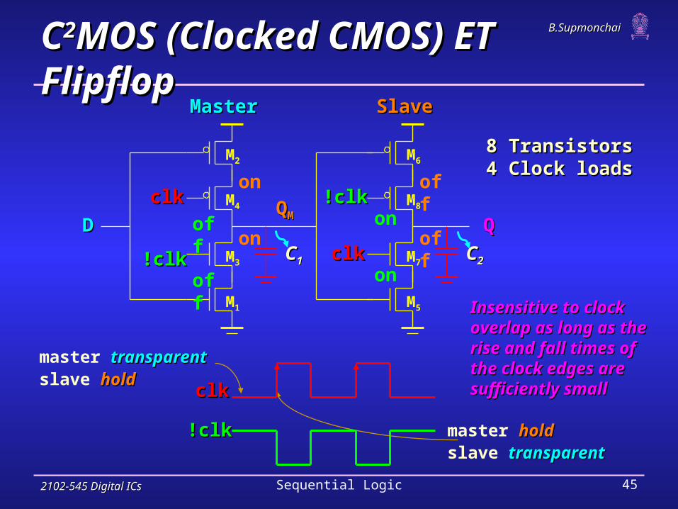
CC22MOS (Clocked CMOS) ET FlipflopMOS (Clocked CMOS) ET Flipflop
!clk!clk
clkclk
8 Transistors8 Transistors4 Clock loads4 Clock loads
Insensitive to clock Insensitive to clock overlap as long as the overlap as long as the rise and fall times of rise and fall times of the clock edges are the clock edges are sufficiently smallsufficiently small
2102-545 Digital ICs2102-545 Digital ICs Sequential Logic 46
B.SupmonchaiB.Supmonchai
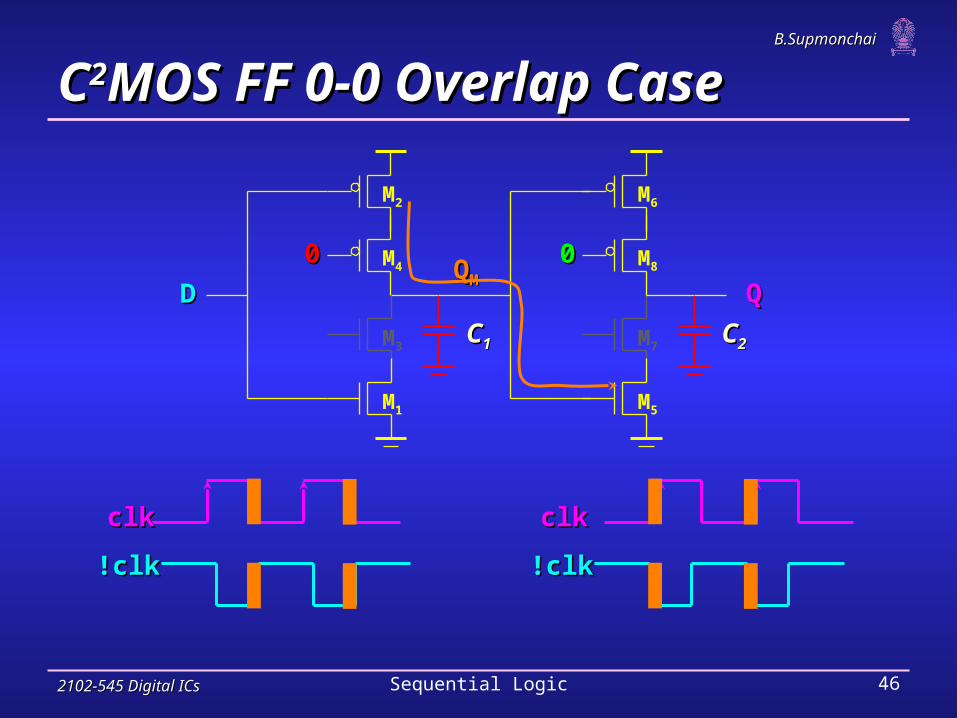
CC22MOS FF 0-0 Overlap CaseMOS FF 0-0 Overlap Case
00 00QQMM
CC11 CC22
QQDD
M1
M3
M4
M2 M6
M8
M7
M5
!clk!clk
clkclk
!clk!clk
clkclk

2102-545 Digital ICs2102-545 Digital ICs Sequential Logic 47
B.SupmonchaiB.Supmonchai
Notes on CNotes on C22MOS FF 0-0 Overlap CaseMOS FF 0-0 Overlap Case Does any new data sampled during the overlap window
propagate to Q (race)? New data is sampled on QM, but cannotcannot propagate to Q since
M7 is off (slave is in hold).
Any new data sampled on the falling clock edge is not seen at Q
For clocking on the left: at the end of the overlap period !clk!clk = 1 and both M7 and M8 turn off, putting the slave in the hold mode
For the clocking on the right: at the end of the overlap period clkclk = 1 and both M3 and M4 turn off, putting the master in the hold mode (affects setup time as well)
The result: the FF is slowerthe FF is slower (slower ttc-qc-q time)

2102-545 Digital ICs2102-545 Digital ICs Sequential Logic 48
B.SupmonchaiB.Supmonchai
!clk!clk
clkclk
!clk!clk
clkclk
1-1 overlap constraint: ttoverlapoverlap1-1 1-1 < < ttholdhold
1111
QQMM
CC11 CC22
QQDD
M1
M3
M4
M2 M6
M8
M7
M5
CC22MOS FF 1-1 Overlap CaseMOS FF 1-1 Overlap Case

2102-545 Digital ICs2102-545 Digital ICs Sequential Logic 49
B.SupmonchaiB.Supmonchai
Notes on CNotes on C22MOS FF 1-1 Overlap CaseMOS FF 1-1 Overlap Case New data is sampled on QM, but cannot propagate to Q
since M8 is off (slave is in hold).
A bit more problematic than 0-0 overlap. It must enforce a hold timehold time on D, so that changing D which
reaches QM is not copied to Q when overlap time is over - first clocking condition. first clocking condition.
By imposing a hold time on D - that D must be stable during clock overlap - overcome this problem as well
However, possible race can occur if the rise/fall times of the clock are sufficiently slow. Works correctly as long as the clock rise/fall times is smaller
than approximately five timesapproximately five times the propagation delay of the flipflop.

2102-545 Digital ICs2102-545 Digital ICs Sequential Logic 50
B.SupmonchaiB.Supmonchai
CC22MOS Transient ResponseMOS Transient Response
Q(3)Q(3)
Q(0.1)Q(0.1)
-0.5
0
0.5
1
1.5
2
2.5
3
0 2 4 6 8
Time (nsec)Time (nsec)
Vo
lts
Vo
lts
clk(0.1 ns)clk(0.1 ns)
QQMM(3)(3)
clk(3 ns)clk(3 ns)
For slow clocks, potential for a race condition existsFor slow clocks, potential for a race condition exists

2102-545 Digital ICs2102-545 Digital ICs Sequential Logic 51
B.SupmonchaiB.Supmonchai
clkclk clkclkInIn
Positive LatchPositive LatchNegative LatchNegative Latch
transparenttransparent when clk = 1holdhold when clk = 0
clkclk clkclkInIn QQ
holdhold when clk = 1transparenttransparent when clk = 0
True Single Phase Clocked (TSPC) LatchesTrue Single Phase Clocked (TSPC) Latches
Uses only a single clock No clock overlap (skew)No clock overlap (skew) to worry about ; reduced clock load

2102-545 Digital ICs2102-545 Digital ICs Sequential Logic 52
B.SupmonchaiB.Supmonchai
clkclk clkclkInInQQ
PUNPUN
PDNPDN
clkclk clkclk
AA
BB
BBAA
Embedding Logic in TSPC LatchEmbedding Logic in TSPC Latch
Logic can be embedded into latch (or FF) Reduce delay overhead associated with the latchReduce delay overhead associated with the latch
A AND BA AND B

2102-545 Digital ICs2102-545 Digital ICs Sequential Logic 53
B.SupmonchaiB.Supmonchai
Notes on Embedding Logic in TSPC LatchNotes on Embedding Logic in TSPC Latch
Set-up time increasedincreased, but overall performance improvedimproved The increase in the set-up time is typically smallertypically smaller than the
delay of an AND gate.
For example, using minimum size devices set-up of AND latch is 140 psec.
Using the conventional approach of AND gate followed by latch has an effective set-up time of 600 psec.
Technique used extensively in the design of the EV4 DEC Alpha microprocessor and many other high performance processors.

2102-545 Digital ICs2102-545 Digital ICs Sequential Logic 54
B.SupmonchaiB.Supmonchai
master holdholdslave transparenttransparent
master master transparenttransparentslave slave holdhold
ononoffoff
on on
offoff clkclk clkclkDD
MasterMaster SlaveSlave
clkclk clkclk QQQQMM
clkclk
12 Transistors12 Transistors 4 Clock loads4 Clock loads
TSPC ET FFTSPC ET FF
Virtually all constraints removed - no clocks to overlap, no raceVirtually all constraints removed - no clocks to overlap, no race

2102-545 Digital ICs2102-545 Digital ICs Sequential Logic 55
B.SupmonchaiB.Supmonchai
Notes on TSPC ET FFNotes on TSPC ET FF Warning!Warning! - similar to C2MOS, TSPC flipflops
malfunction when the slope of the clock is not when the slope of the clock is not sufficiently steepsufficiently steep. Slow clock cause both the NMOS and PMOS
clocked transistors to be ON simultaneously, resulting in undefined values of the states and race conditions.
Clock slopes thus must be carefully engineered. If necessary, local buffers must be introduced to ensure the quality of the clock signal

2102-545 Digital ICs2102-545 Digital ICs Sequential Logic 56
B.SupmonchaiB.Supmonchai
clkclkDD clkclkQQ
clkclk
clkclk
XXYY
M1
M2
M3 M6
M5
M4 M7
M8
M9
I1I1 I2I2 I3I3
Simplified TSPC ET FFSimplified TSPC ET FF
I1 holdholdI2 evaluateevaluateI3 sample (transparentsample (transparent)
I1 sample (transparent)sample (transparent)I2 prechargedprechargedI3 holdhold
onoff
on
off
D D
clkclk
on
on
off
off
1
!D
9 Transistors*9 Transistors*4 Clock loads4 Clock loads*(11 if Q is needed)*(11 if Q is needed)

2102-545 Digital ICs2102-545 Digital ICs Sequential Logic 57
B.SupmonchaiB.Supmonchai
Notes on TSPC ET FFNotes on TSPC ET FF On the positive edge of the clock, note that the node X
transitions to a low if D is high. Therefore, the input must be kept stable until the value on node X before the rising edge of the clock propagates to Y Hold time of the register (less than 1 inverter delay since it
takes 1 inverter delay for the input to affect node X).
Propagation delay is essentially three inverters since Propagation delay is essentially three inverters since the value on node X must propagate to output Qthe value on node X must propagate to output Q
Set-up time is the time for node X to be valid – one one inverter delayinverter delay

2102-545 Digital ICs2102-545 Digital ICs Sequential Logic 58
B.SupmonchaiB.Supmonchai
Sizing Issues in Simplified TSPC ET FFSizing Issues in Simplified TSPC ET FF
0
1
2
3
0 0.2 0.4 0.6 0.8 1
Time (nsec)
Vo
lts
clk
!Qorig
Qorig
!Qmod
Qmod
Transistor sizing
Original widthOriginal width MM44, M, M55 = 0.5 = 0.5mm
MM77, M, M88 = 2 = 2mm
Modified widthModified width MM44, M, M55 = 1 = 1mm
MM77, M, M88 = 1 = 1mm
Sizing is critical – with improper sizing glitches may occur due Sizing is critical – with improper sizing glitches may occur due to race condition when the clock transitions from low to highto race condition when the clock transitions from low to high

2102-545 Digital ICs2102-545 Digital ICs Sequential Logic 59
B.SupmonchaiB.Supmonchai
Positive LatchPositive Latch Negative LatchNegative Latch
transparenttransparent when clk = 1 when clk = 1holdhold when clk = 0 when clk = 0
holdhold when clk = 1 when clk = 1transparenttransparent when clk = 0 when clk = 0
clkclkInInQQ
AAclkclkInIn QQ
AA
When When InIn = 0, = 0, AA = V = VDDDD - V - VTnTn When When InIn = 1, = 1, AA = | V = | VTp Tp ||
Split-Output TSPC LatchesSplit-Output TSPC Latches

2102-545 Digital ICs2102-545 Digital ICs Sequential Logic 60
B.SupmonchaiB.Supmonchai
Split-Output TSPC ET FFSplit-Output TSPC ET FF
8 Transistors*8 Transistors*2 Clock loads2 Clock loads*(10 if Q is needed)*(10 if Q is needed)
Which edge-triggered?Which edge-triggered?
Downside is not all node voltages in the latch experience full logic swing due to threshold drop. E.g., for positive latch when DD=0 and clkclk=1, AA=Vdd-Vth (Also
limits the amount of Vdd scaling possible with this latch).
clkclkDD
QQclkclk QQMM
AA

2102-545 Digital ICs2102-545 Digital ICs Sequential Logic 61
B.SupmonchaiB.Supmonchai
Master-Slave FlipflopMaster-Slave Flipflop Pulse-Triggered FlipflopPulse-Triggered Flipflop
D
ClkClk
Q D
ClkClk
Q
ClkClk
DataDataL1L1 L2L2
Pulse-Triggered FlipflopsPulse-Triggered Flipflops Another approach to design an edge-triggered
flipflop is to use pulse-triggeredpulse-triggered.
LLDataData
D
ClkClk
Q
ClkClk

2102-545 Digital ICs2102-545 Digital ICs Sequential Logic 62
B.SupmonchaiB.Supmonchai
0 ONVdd
OFF OFF
11 0ON
XXclkclk
DD
M1
M2
M3
M4
M5
M6
P1
P2
P3
!clkd!clkd
1/0ON/OFF
0/Vdd ON/OFF
1/0
0 OFF
1
1OFF
ON ON
ON
Pulsed FF (AMD-K6)Pulsed FF (AMD-K6) Pulse registers - a short pulse (glitch clock) is generated
locally locally from the rising (or falling) edge of the system clock and is used as the clock input to the flipflop

2102-545 Digital ICs2102-545 Digital ICs Sequential Logic 63
B.SupmonchaiB.Supmonchai
Notes on Pulsed FFNotes on Pulsed FF Race conditions are avoided by keeping the transparent
mode time very shortvery short (during the pulse only)
Reduce clock load but substantially increase complexity in verification
The transparency period determines the hold time. The window must be wide enoughwide enough for the input data to
propagate to Q.
The set-up time can be NEGATIVENEGATIVE (if the transparency window is longer than the delay from input to output). This is attractive, as data can arrive at the register even afterafter
the clock goes high, meaning that time can be borrowed from the previous cycle.

2102-545 Digital ICs2102-545 Digital ICs Sequential Logic 64
B.SupmonchaiB.Supmonchai
0
0
1
1
1
1
1
0
1
0
1
Sense Amp FF (StrongArm SA100)Sense Amp FF (StrongArm SA100) Sense amplifierSense amplifier is a circuit that accept small swing input
signals and amplify them to full rail-to-rail signals
clkclk
DD
!Q!Q
M1
M2
M3
M5
M6
M4
M9
M7
M8
M10
!S!S
!R!R
XX
YY

2102-545 Digital ICs2102-545 Digital ICs Sequential Logic 65
B.SupmonchaiB.Supmonchai
Notes on Sensed Amp FFNotes on Sensed Amp FF The key is transistor M4transistor M4 (in the middle of Sensed amp);
it delays signals that pass through to the other side of its terminal, making the change on the other side slower When D = 1, Y changes after X due to the delay of M4. By the
time M6 reacts to the change at its terminal, it is already turned off by the terminal voltage at M4 (a 0). Thus, M6 holds a 1.
M4 also provides DC-leakage path to ground for either node X or Y in case that the inputs change their value after the positive edge of CLKCLK arrives.
Advantages are reduced clock loadreduced clock load and that it can be used as a receiver for reduced swing differential buses Where does the differential signal enter?

2102-545 Digital ICs2102-545 Digital ICs Sequential Logic 66
B.SupmonchaiB.Supmonchai
Flipflop Comparison ChartFlipflop Comparison Chart
NameName TypeType #clk ld#clk ld #tr#tr ttset-upset-up ttholdhold ttpFFpFF
Mux Static 8 (clk-!clk) 20 3t3tpinvpinv++ttptxptx 0 tpinv+tptx
PowerPC Static 8 (clk-!clk) 16
2-phase Ps-Static 8 (clk1-clk2) 16
T-gate Dynamic 4 (clk-!clk) 8 ttptxptx ttoo1-11-1 2t2tpinvpinv++ttptxptx
C2MOS Dynamic 4 (clk-!clk) 8
TSPC Dynamic 4 (clk) 11 ttpinvpinv ttpinvpinv 3t3tpinvpinv
S-O TSPC Dynamic 2 (clk) 10
AMD K6 Dynamic 5 (clk) 19
SA 100 SenseAmp 3 (clk) 20

2102-545 Digital ICs2102-545 Digital ICs Sequential Logic 67
B.SupmonchaiB.Supmonchai
Choosing a Clocking StrategyChoosing a Clocking Strategy Choosing the right clocking scheme affects the
functionalityfunctionality, speedspeed, and powerpower of a circuit
Two-phase designsTwo-phase designs ++ robust and conceptually simple -- need to generate and route two clock signals -- have to design to accommodate possible skew between the
two clock signals
Single phase designsSingle phase designs ++ only need to generate and route one clock signal ++ supported by most automated design methodologies ++ don’t have to worry about skew between the two clocks -- have to have guaranteed slopes on the clock edges

2102-545 Digital ICs2102-545 Digital ICs Sequential Logic 68
B.SupmonchaiB.Supmonchai
Non-Bistable Sequential CircuitsNon-Bistable Sequential Circuits Previously, we have defined a circuit having two
stable states a bi-stable circuit
Other regenerative circuits, which are non-bistable: MonostableMonostable
Only one stable state -> Pulse generators, One-shot circuits
AstableAstable No stable states -> Oscillator, On-chip clock generator
Schmitt TriggerSchmitt Trigger A special regenerative circuit exhibiting hysteresishysteresis in VTC.

2102-545 Digital ICs2102-545 Digital ICs Sequential Logic 69
B.SupmonchaiB.Supmonchai
In Out
Schmitt TriggerSchmitt Trigger
Non-Bistable Sequential CircuitsNon-Bistable Sequential Circuits
Vin
VoutVOH
VOL
VM– VM+
2 important properties HysteresisHysteresis
Fast Transition TimeFast Transition Time at the output

2102-545 Digital ICs2102-545 Digital ICs Sequential Logic 70
B.SupmonchaiB.Supmonchai
Noise Suppression using Schmitt TriggerNoise Suppression using Schmitt Trigger
VVININ
tt00 tt
VVM+M+
VVM-M-
VVOUTOUT
tttt00 + t+ tpp
Example: Switch DebouncerExample: Switch Debouncer

2102-545 Digital ICs2102-545 Digital ICs Sequential Logic 71
B.SupmonchaiB.Supmonchai
CMOS Schmitt TriggerCMOS Schmitt Trigger
M1
M4M2
M3
VVININ VVOUTOUT
XX
VVDDDD
Moves switching Moves switching threshold of the threshold of the first inverterfirst inverter
Adapting the ratio between PMOS and NMOS, depending upon the Adapting the ratio between PMOS and NMOS, depending upon the direction of the transition results in a shift in switching thresholddirection of the transition results in a shift in switching threshold
Low-to-High rreffeff = k = kMM11/(/(kkMM22 + + kkMM44))
High-to-Low rreffeff = = ((kkMM11 + + kkMM33)/)/kkMM22

2102-545 Digital ICs2102-545 Digital ICs Sequential Logic 72
B.SupmonchaiB.Supmonchai
Schmitt Trigger Simulated VTCSchmitt Trigger Simulated VTC
2.5
VM2
VM1
Vin (V)
2.0
1.5
1.0
0.5
0.00.0 0.5 1.0 1.5 2.0 2.5
Vou
t(V)
2.5
k = 2k = 3
k = 4
k = 1
Vin (V)
2.0
1.5
1.0
0.5
0.00.0 0.5 1.0 1.5 2.0 2.5
Vou
t(V)
Effect of varying the ratio of the Effect of varying the ratio of the PMOS device M4PMOS device M4
Voltage Transfer Characteristics Voltage Transfer Characteristics with with hysteresishysteresis
M1 = 1 M1 = 1 m/0.25 m/0.25 m, M2 = 3 m, M2 = 3 m/0.25 m/0.25 m, M3 = 0.5 m, M3 = 0.5 m/0.25 m/0.25 mm
M4 = 1.5 M4 = 1.5 m/0.25 m/0.25 mm M4 = M4 = kk x 0.5 x 0.5 m/0.25 m/0.25 mm

2102-545 Digital ICs2102-545 Digital ICs Sequential Logic 73
B.SupmonchaiB.Supmonchai
CMOS Schmitt Trigger (2)CMOS Schmitt Trigger (2)
How does the gate operate?How does the gate operate?
M2
VVININ VVOUTOUT
XXM1
M5
M6
M3
M4
Sketch VTC and find expression for VSketch VTC and find expression for VM-M- and V and VM+M+

2102-545 Digital ICs2102-545 Digital ICs Sequential Logic 74
B.SupmonchaiB.Supmonchai
Review: Ring OscillatorReview: Ring Oscillator
0.0
0.0
0.5
1.0
1.5
2.0
2.5V1 V3 V5
3.0
20.50.5
time (ns)
1.0 1.5
Period: Period: TT = 2 x = 2 x ttpp x x NN
ttpp
Different Clock Duty-Cycles Different Clock Duty-Cycles and phases can be derived and phases can be derived using simple logic operationsusing simple logic operations

2102-545 Digital ICs2102-545 Digital ICs Sequential Logic 75
B.SupmonchaiB.Supmonchai
In
VDD
M3
M1
M2
M4
M5
VDD
M6
Vcontr Current starved inverter
Iref Iref
Schmitt Triggerrestores signal slopes
0.5 1.5 2.5Vcontr (V)
0.0
2
4
6
tpHL (
nsec)
propagation delay as a functionof control voltage
Voltage Controller Oscillator (VCO)Voltage Controller Oscillator (VCO) Oscillation frequency of a VCO is a function (typically
nonlinear) of a control voltage
Delay of a current starved inverter depends on the current Delay of a current starved inverter depends on the current limit available to discharge the load capacitance of the gatelimit available to discharge the load capacitance of the gate

2102-545 Digital ICs2102-545 Digital ICs Sequential Logic 76
B.SupmonchaiB.Supmonchai
Current-Starved Inverter SimulationCurrent-Starved Inverter Simulation
In
VDD
M3
M1
M2
M4
M5
VDD
M6
Vcontr Current starved inverter
Iref Iref
Schmitt Triggerrestores signal slopes
0.5 1.5 2.5Vcontr (V)
0.0
2
4
6
tpHL (
nsec)
propagation delay as a functionof control voltage
Vctrl (V)
t pH
L (
nse
c)
The device is in the subthreshold region when VVctrlctrl is smaller than VVTT, resulting in large variations of ttpp as the drive current is exponentially dependent on the drive voltage Delay sensitive to Delay sensitive to
noise and variation noise and variation in Vin Vctrlctrl

2102-545 Digital ICs2102-545 Digital ICs Sequential Logic 77
B.SupmonchaiB.Supmonchai
Differential Delay Element and VCODifferential Delay Element and VCO
two stage VCOtwo stage VCO
v1v2
v3
v4
-- Inverting Inverting Inputs/Outputs Inputs/Outputs+ Non-Inverting+ Non-Inverting Inputs/Outputs Inputs/Outputs
Oscillator with even number Oscillator with even number of stages can be implementedof stages can be implemented
in2
Vctrl
Vo2 Vo1
in1
delay celldelay cell
++
++
--
--
Differential-type VCO has better immunity to common Differential-type VCO has better immunity to common mode noise (e.g., supply noise) but mode noise (e.g., supply noise) but consume more powerconsume more power

2102-545 Digital ICs2102-545 Digital ICs Sequential Logic 78
B.SupmonchaiB.Supmonchai
2-Stage VCO Simulation2-Stage VCO Simulation
0.5
0.0
0.5
1.0
1.5
2.0
2.5
3.0
2 0.51.5
V1 V2 V3 V4
time (ns)
2.5 3.5
The In-Phase and Quadrature Phase are produced simultaneouslyThe In-Phase and Quadrature Phase are produced simultaneously