chapter 720 bridges - core.ac.uk
TRANSCRIPT

WSDOT Design Manual M 22-01.09 Page 720-1 July 2012
Chapter 720 Bridges
720.01 General 720.02 References 720.03 Bridge Locations 720.04 Bridge Site Design Elements 720.05 Documentation
720.01 General
The National Bridge Inspection Standards (NBIS), published in the Code of Federal Regulations (23 CFR 650, Subpart C), defines a bridge as:
A structure including supports erected over a depression or an obstruction, such as water, highway, or railway, and having a track or passageway for carrying traffic or other moving loads, and having an opening measured along the center of the roadway of more than 20 feet between undercopings of abutments or spring lines of arches, or extreme ends of openings for multiple boxes; it may also include multiple pipes, where the clear distance between openings is less than half of the smaller contiguous opening.
Bridge design is the responsibility of the Washington State Department of Transportation (WSDOT) Headquarters (HQ) Bridge and Structures Office, which develops a preliminary bridge plan for a new or modified structure in collaboration with the region. This chapter provides basic design considerations for the development of this plan. Unique staging requirements, constructability issues, and other considerations are addressed during plan development. Contact the HQ Bridge and Structures Office early in the planning stage regarding issues that might affect the planned project (see Chapter 700). A Project File (PF) is required for all bridge construction projects.
720.02 References
(1) Federal/State Laws and Codes 23 CFR Part 650, Subpart C – National Bridge Inspection Standards
Washington Administrative Code (WAC) 480-60, Railroad companies – Clearances
(2) Design Guidance Bridge Design Manual, M 23-50, WSDOT
Geotechnical Design Manual, M 46-03, WSDOT
Local Agency Guidelines (LAG), M 36-63, WSDOT
LRFD Bridge Design Specifications, 4th Edition, Washington DC, AASHTO, 2007
Manual on Uniform Traffic Control Devices for Streets and Highways, USDOT, FHWA; as adopted and modified by Chapter 468-95 WAC “Manual on uniform traffic control devices for streets and highways” (MUTCD)
Standard Plans for Road, Bridge, and Municipal Construction (Standard Plans), M 21-10, WSDOT
brought to you by COREView metadata, citation and similar papers at core.ac.uk
provided by CiteSeerX

Bridges Chapter 720
Page 720-2 WSDOT Design Manual M 22-01.09 July 2012
Standard Specifications for Road, Bridge, and Municipal Construction (Standard Specifications), M 41-10, WSDOT
Traffic Manual, M 51-02, WSDOT
(3) Supporting Information A Policy on Geometric Design of Highways and Streets (Green Book), AASHTO, 2004
Manual for Railway Engineering, American Railway Engineering and Maintenance-of-Way Association (AREMA), 2006
720.03 Bridge Locations
Bridge locations are chosen to conform to the alignment of the highway. Conditions that can simplify design efforts, minimize construction activities, and reduce structure costs are:
• A perpendicular crossing.
• The minimum required horizontal and vertical clearances.
• A constant bridge width (without tapered sections).
• A tangential approach alignment of sufficient length not to require superelevation on the bridge.
• A crest vertical curve profile that will facilitate drainage.
• An adequate construction staging area.
720.04 Bridge Site Design Elements
(1) Structural Capacity
The structural capacity of a bridge is a measure of the structure’s ability to carry vehicle loads. For new bridges, the bridge designer chooses the design load that determines the structural capacity. For existing bridges, the structural capacity is calculated to determine the “load rating” of the bridge. The load rating is used to determine whether or not a bridge is “posted” for legal weight vehicles or “restricted” for overweight permit vehicles.
(a) New Structures
All new structures that carry vehicular loads are designed to HL-93 notional live load in accordance with AASHTO’s LRFD Bridge Design Specifications.
(b) Existing Structures
When the Structural Capacity column of a design matrix applies to the project, request a Structural Capacity Report from the Risk Reduction Engineer in the HQ Bridge and Structures Office. The report will state:
• The structural capacity status of the structures within the project limits.
• What action, if any, is appropriate.
• Whether a deficient bridge is included in the 6-year or 20-year plans for replacement or rehabilitation under the P2 program and, if so, in which biennium the P2 project is likely to be funded.

Chapter 720 Bridges
WSDOT Design Manual M 22-01.09 Page 720-3 July 2012
Include the Structural Capacity Report in the Design Documentation Package (DDP).
The considerations used to evaluate the structural capacity of a bridge are as follows:
1. On National Highway System (NHS) routes (including Interstate routes):
• The operating load rating is at least 36 tons (which is equal to HS-20).
• The bridge is not permanently posted for legal weight vehicles.
• The bridge is not permanently restricted for vehicles requiring overweight permits.
2. On non-NHS routes:
• The bridge is not permanently posted for legal weight vehicles.
• The bridge is not permanently restricted for vehicles requiring overweight permits.
(2) Bridge Widths for Structures
(a) New Structures
Full design level widths are provided on all new structures (see Chapter 1140). All structures on city or county routes crossing over a state highway must conform to the Local Agency Guidelines. Use local city or county adopted and applied criteria when their minimum width exceeds state criteria.
(b) Existing Structures
For guidance on existing structures, see the design matrices in Chapter 1100.
(3) Horizontal Clearance
Horizontal clearance for structures is the distance from the edge of the traveled way to bridge piers and abutments, traffic barrier ends, or bridge end embankment slopes. Minimum distances for this clearance vary depending on the type of structure. (See Chapters 1600 and 1610 and the Bridge Design Manual for guidance on horizontal clearance.)
For structures involving railroads, contact the HQ Design Office Railroad Liaison.
(4) Bridge Medians
Designs for bridges on divided multilane highways often include the decision to join parallel bridges as one or build them as independent structures. There are several factors in this decision, such as in new corridor construction, phased construction of corridors over time, and the general median width of the divided highway. This section covers some common design considerations related to bridge medians.
For divided multilane highways, the minimum median widths for new bridges are as shown in Chapters 1130 and 1140. Chapter 1230 provides minimum design criteria for medians. Chapter 1230 indicates that independent horizontal and vertical alignments are desirable on divided highways, particularly in rural settings.

Bridges Chapter 720
Page 720-4 WSDOT Design Manual M 22-01.09 July 2012
Past Design Manual guidance on bridge medians stated a preference for joining two parallel structures as one, based on the distance between the structures. This guidance originated from a concern that errant vehicles may travel into the open space between two separate, parallel structures. Joining the two roadways on a single bridge and separating traffic with median barrier addressed this concern. Errant motorists occur on highways, and reducing the crash severity of these types of collision remains a priority for WSDOT. Advances in crash barriers and their applications have resulted in an expanded set of choices for bridge medians on divided highways.
Changed barrier designs and applications have allowed for longer runs of traffic barrier, different barrier types, and bullnose guardrail designs for shielding the gap between parallel structures. These tools have reduced collisions with abrupt bridge ends as well as shielded the opening between bridges.
WSDOT designers today encounter varying constraints, tradeoffs and existing contexts, along with limited project scopes and budgets. With fewer new corridors being constructed, many WSDOT projects are devoted to preservation of the mature highway system, leading to additional project considerations and tradeoffs.
Some highway corridors are initially planned as multilane divided highways but may be developed in logical, affordable phases and individual projects. This could result in an initial phase where a corridor may open as a two-lane rural highway used by both travel directions. A later phase could convert the facility to a divided highway, bringing with it the need for median separation. Consider the long-range plans when determining median widths for bridges. The photos in Exhibit 720-4 show a completed multilane highway where two separate bridges were ultimately constructed years apart and a new corridor underway where one bridge is now built.
Joining two structures may not be the most cost-effective or sustainable solution for all projects. Coordinate with the Bridge and Structures Office and the local Maintenance Office when discussing options and concerns. For bridges on parallel horizontal and vertical alignments, practical considerations for joining two structures as one include, but are not limited to:
• Phased development where one structure exists and another is planned.
• Old and new structure types and compatibility (with phased corridor construction).
• Median width.
• Median barrier treatment options.
• Environmental contexts and regulations.
• Seismic conditions and load ratings.
• Bridge maintenance and inspection techniques: accessibility options and equipment for terrain in specific contexts. An open area between structures may be needed for bridge inspection.
• Economics.
• Historical/aesthetic value of existing bridges to remain in place.
Document this evaluation in the Design Documentation Package.

Chapter 720 Bridges
WSDOT Design Manual M 22-01.09 Page 720-5 July 2012
(5) Vertical Clearance
Vertical clearance is the critical height under a structure that will accommodate vehicular and rail traffic based on its design characteristics. This height is the least height available from the lower roadway surface (including usable shoulders) or the plane of the top of the rails to the bottom of the bridge. Usable shoulders are the design shoulders for the roadway and do not include paved widened areas that may exist under the structure.
In addition to the following vertical clearance guidance, consider whether the corridor experiences overheight loads. Consider a vertical clearance such that it will not create a new “low point” in the corridor.
(a) Vertical Falsework Clearance for Bridges Over Highways
Construction of new bridges and the reconstruction or widening of existing structures often requires the erection of falsework across the traveled way of a highway. The erection of this falsework can reduce the vertical clearance for vehicles to pass under the work area. The potential for collisions to occur by hitting this lower construction stage falsework is increased.
1. On all routes that require a 16-foot-6-inch vertical clearance, maintain the 16-foot-6-inch clearance for falsework vertical clearance.
• On structures that currently have less than a 16-foot-6-inch vertical clearance for the falsework envelope, maintain existing clearance.
• On new structures, maintain the falsework vertical clearance at least to those of the minimum vertical clearances referenced below.
2. Any variance from the above must be approved by the Regional Administrator or designee in writing and made a part of the Project File.
(b) Minimum Clearance for New Structures
For new structures, the minimum vertical clearances are as follows:
1. Bridge Over a Roadway
The minimum vertical clearance for a bridge over a roadway is 16.5 feet.
2. Bridge Over a Railroad Track
The minimum vertical clearance for a bridge over a railroad track is 23.5 feet (see Exhibit 720-2). A lesser clearance may be negotiated with the railroad company based on certain operational characteristics of the rail line; however, any clearance less than 22.5 feet requires the approval of the Washington State Utilities and Transportation Commission (WUTC) per WAC 480-60. Vertical clearance is provided for the width of the railroad clearance envelope. Coordinate railroad clearance issues with the HQ Design Office Railroad Liaison.
3. Pedestrian Bridge Over a Roadway
The minimum vertical clearance for a pedestrian bridge over a roadway is 17.5 feet.

Bridges Chapter 720
Page 720-6 WSDOT Design Manual M 22-01.09 July 2012
Project Type Vertical
Clearance[8]
Documentation Requirement (see notes)
Interstate and Other Freeways[1]
New Bridge > 16.5 ft [2]
Widening Over or Under Existing Bridge > 16 ft [2] < 16 ft [4]
Resurfacing Under Existing Bridge > 16 ft [2] < 16 ft [4]
Other With No Change to Vertical Clearance > 14.5 ft [3] < 14.5 ft [4]
Nonfreeway Routes New Bridge > 16.5 ft [2]
Widening Over or Under Existing Bridge > 15.5 ft [2] < 15.5 ft [4]
Resurfacing Under Existing Bridge > 15.5 ft [2] < 15.5 ft [4]
Other With No Change to Vertical Clearance > 14.5 ft [3] < 14.5 ft [4]
Bridge Over Railroad Tracks[7]
New Bridge > 23.5 ft < 23.5 ft
[2] [4][5]
Existing Bridge > 22.5 ft < 22.5 ft
[2] [4][5]
Pedestrian Bridge Over Roadway New Bridge > 17.5 ft [2] Existing Bridge 17.5 ft [6]
Notes:
[1] Applies to all bridge vertical clearances over highways and under highways at interchanges. [2] No documentation required. [3] Document to Design Documentation Package. [4] Approved deviation required. [5] Requires written agreement between railroad company and WSDOT and approval via petition
from the WUTC. [6] Maintain 17.5-ft clearance. [7] Coordinate railroad clearance with the HQ Design Office Railroad Liaison. [8] See 720.04(5).
Bridge Vertical Clearances Exhibit 720-1

Chapter 720 Bridges
WSDOT Design Manual M 22-01.09 Page 720-7 July 2012
(c) Minimum Clearance for Existing Structures
The criteria used to evaluate the vertical clearance for existing structures depend on the work being done on or under that structure. When evaluating an existing structure on the Interstate System, see 720.04(5)(e), Coordination. This guidance applies to bridge clearances over state highways and under state highways at interchanges. For state highways over local roads and streets, city or county vertical clearance requirements may be used as minimum design criteria. (See Exhibit 720-1 for bridge vertical clearances.)
1. Bridge Over a Roadway
For a project that will widen an existing structure over a highway or where the highway will be widened under an existing structure, the vertical clearance can be as little as 16.0 feet on the Interstate System or other freeways or 15.5 feet on nonfreeway routes. An approved deviation is required for clearance less than 16.0 feet on Interstate routes or other freeways and 15.5 feet on nonfreeway routes.
For a planned resurfacing of the highway under an existing bridge, if the clearance will be less than 16.0 feet on the Interstate System or other freeways and 15.5 feet on nonfreeway routes, evaluate the following options and include in a deviation request:
• Pavement removal and replacement.
• Roadway excavation and reconstruction to lower the roadway profile.
• Providing a new bridge with the required vertical clearance.
Reducing roadway paving and surfacing thickness under the bridge to achieve the minimum vertical clearance can cause accelerated deterioration of the highway and is not recommended. Elimination of the planned resurfacing in the immediate area of the bridge might be a short-term solution if recommended by the Region Materials Engineer (RME). Solutions that include milling the existing surface followed by overlay or inlay must be approved by the RME to ensure adequate pavement structure is provided.
For other projects that include an existing bridge where no widening is proposed on or under the bridge, and the project does not affect vertical clearance, the clearance can be as little as 14.5 feet. For these projects, document the clearance in the Design Documentation Package. For an existing bridge with less than a 14.5-foot vertical clearance, an approved deviation request is required.
2. Bridge Over a Railroad Track
For an existing structure over a railroad track, the vertical clearance can be as little as 22.5 feet. A lesser clearance can be used with the agreement of the railroad company and the approval of the Washington State Utilities and Transportation Commission. Coordinate railroad clearance issues with the HQ Design Office Railroad Liaison.
Bridges Chapter 720
Page 720-8 WSDOT Design Manual M 22-01.10 July 2013
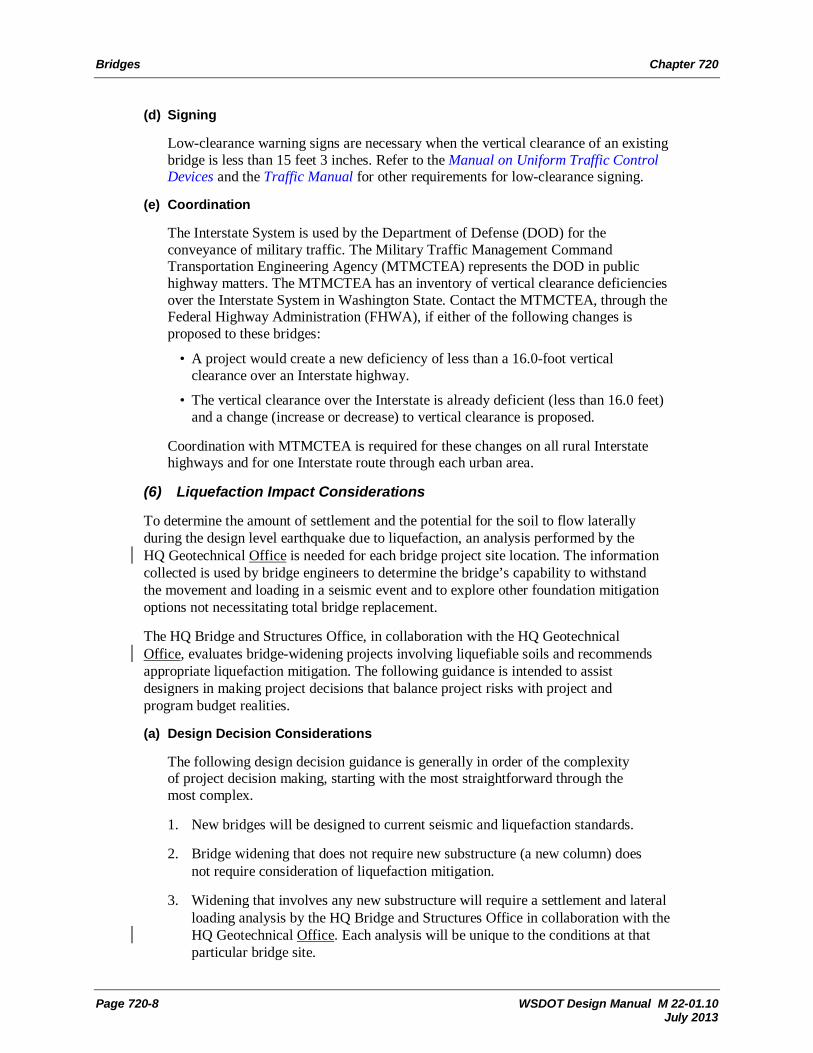
(d) Signing
Low-clearance warning signs are necessary when the vertical clearance of an existing bridge is less than 15 feet 3 inches. Refer to the Manual on Uniform Traffic Control Devices and the Traffic Manual for other requirements for low-clearance signing.
(e) Coordination
The Interstate System is used by the Department of Defense (DOD) for the conveyance of military traffic. The Military Traffic Management Command Transportation Engineering Agency (MTMCTEA) represents the DOD in public highway matters. The MTMCTEA has an inventory of vertical clearance deficiencies over the Interstate System in Washington State. Contact the MTMCTEA, through the Federal Highway Administration (FHWA), if either of the following changes is proposed to these bridges:
• A project would create a new deficiency of less than a 16.0-foot vertical clearance over an Interstate highway.
• The vertical clearance over the Interstate is already deficient (less than 16.0 feet) and a change (increase or decrease) to vertical clearance is proposed.
Coordination with MTMCTEA is required for these changes on all rural Interstate highways and for one Interstate route through each urban area.
(6) Liquefaction Impact Considerations
To determine the amount of settlement and the potential for the soil to flow laterally during the design level earthquake due to liquefaction, an analysis performed by the HQ Geotechnical Office is needed for each bridge project site location. The information collected is used by bridge engineers to determine the bridge’s capability to withstand the movement and loading in a seismic event and to explore other foundation mitigation options not necessitating total bridge replacement.
The HQ Bridge and Structures Office, in collaboration with the HQ Geotechnical Office, evaluates bridge-widening projects involving liquefiable soils and recommends appropriate liquefaction mitigation. The following guidance is intended to assist designers in making project decisions that balance project risks with project and program budget realities.
(a) Design Decision Considerations
The following design decision guidance is generally in order of the complexity of project decision making, starting with the most straightforward through the most complex.
1. New bridges will be designed to current seismic and liquefaction standards.
2. Bridge widening that does not require new substructure (a new column) does not require consideration of liquefaction mitigation.
3. Widening that involves any new substructure will require a settlement and lateral loading analysis by the HQ Bridge and Structures Office in collaboration with the HQ Geotechnical Office. Each analysis will be unique to the conditions at that particular bridge site.

Chapter 720 Bridges
WSDOT Design Manual M 22-01.10 Page 720-9 July 2013
a. If a bridge has less than 15 years of its service life remaining, no liquefaction mitigation is necessary according to FHWA guidelines.
b. If the HQ Geotechnical Office analysis demonstrates that the differential settlement induced by liquefaction between the existing bridge and the widened portion will not create forces great enough to cause collapse of the existing bridge, and if lateral loading and movement caused by the liquefaction is minimal, liquefaction mitigation may not be necessary. The decision must be endorsed by the State Geotechnical Engineer, the State Bridge Engineer and the Regional Administrator. The decision and rationale are to be included in the Design Documentation Package.
c. If the HQ Geotechnical Office analysis demonstrates that the differential settlement induced by liquefaction or the lateral loading and movement will be substantial and these movements will result in the collapse of the existing and widened portion of the bridge, additional analysis and documentation are necessary for the project to proceed. A preliminary design and estimate of the mitigation necessary to prevent collapse needs to be performed. Consider alternative designs that eliminate or reduce the need for the widening.
(b) Deferring Liquefaction Mitigation
1. Consideration of Deferment
If an alternative design concept is not feasible given the constraints of the project or program, consideration may be given to defer the liquefaction mitigation. Project-related structural retrofits that are deferred because of scope-related issues are to be considered for implementation through the WSDOT seismic retrofit program. The operating characteristics of the roadway and overall estimated cost of the liquefaction mitigation is typically considered in making that decision.
2. Deferment Requires Approval
A decision to defer the mitigation to the seismic retrofit program is made by the WSDOT Chief Engineer after reviewing and considering the alternatives. The decision is to be included in the Design Documentation Package (DDP). A memo from the Chief Engineer will be provided to the structural designer of record documenting the agency’s decision to defer the mitigation work to the WSDOT seismic retrofit program. A copy of the memo is to be included in the DDP and the contract general notes.
(7) Pedestrian and Bicycle Facilities
When pedestrians or bicyclists are anticipated on bridges, provide facilities consistent with guidance in Chapters 1510, 1515, and 1520. For instances where pedestrian users are not anticipated, evaluate the potential for stranded motorists to become pedestrians, where they may have exited their vehicle after a breakdown or other emergency. The infrequent and random nature of these occurrences makes it difficult to identify locations with even a moderate probability of pedestrian exposure.

Bridges Chapter 720
Page 720-10 WSDOT Design Manual M 22-01.09 July 2012
Evolving programs and technologies such as incident response, personal cell phones, and ITS cameras have further reduced the probability of motorists becoming pedestrians. Investigate other methods of treatment such as pedestrian scale signing or other low-cost safety improvement measures. Document decisions in the DDP.
(8) Bridge Approach Slab
Bridge approach slabs are reinforced concrete pavement installed across the full width of the bridge ends. They provide a stable transition from normal roadway cross section to the bridge ends, and they compensate for differential expansion and contraction of the bridge and the roadway.
Bridge approach slabs are provided on all new bridges. If an existing bridge is being widened and it has an approach slab, slabs are required on the widenings. The region, with the concurrence of the State Geotechnical Engineer and the State Bridge Engineer, may decide to omit bridge approach slabs.
(9) Traffic Barrier End Treatment
Plans for new bridge construction and bridge traffic barrier modifications include provisions for the connection of bridge traffic barriers to the longitudinal barrier approaching and departing the bridge. Indicate the preferred longitudinal barrier type and connection during the review of the bridge preliminary plan.
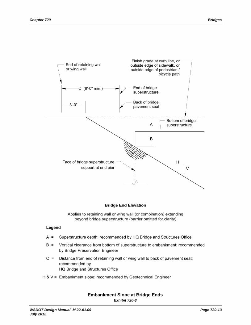
(10) Bridge End Embankments
The design of embankment slopes at bridge ends depends on several factors. The width of the embankment is determined not only by the width of the roadway, but also by the presence of traffic barriers, curbs, and sidewalks, all of which create the need for additional widening. Examples of the additional widening required for these conditions are shown in the Standard Plans.
The end slope is determined by combining the recommendations of several technical experts within WSDOT. Exhibit 720-3 illustrates the factors taken into consideration and the experts involved in the process.
(11) Bridge Slope Protection
Slope protection provides a protective and aesthetic surface for exposed slopes under bridges. Slope protection is normally provided under:
• Structures over state highways.
• Structures within an interchange.
• Structures over other public roads unless requested otherwise by the public agency.
• Railroad overcrossings if requested by the railroad.
Slope protection is usually not provided under pedestrian structures.
The type of slope protection is selected at the bridge preliminary plan stage. Typical slope protection types are concrete slope protection, semi-open concrete masonry, and rubble stone.

Chapter 720 Bridges
WSDOT Design Manual M 22-01.09 Page 720-11 July 2012
(12) Slope Protection at Water Crossings
The HQ Hydraulics Section determines the slope protection requirements for structures that cross waterways. The type, limits, and quantity of slope protection are shown on the bridge preliminary plan.
(13) Screening for Highway Structures
The Washington State Patrol (WSP) classifies the throwing of an object from a highway structure as an assault, not an accident. Therefore, records of these assaults are not contained in WSDOT’s collision databases. Contact the Region Traffic Engineer, RME’s office and the WSP for the history of reported incidents.
Screening might reduce the number of incidents, but will not stop a determined individual at that location, or deter them from moving to other locations in the area. Enforcement provides the most effective deterrent and is typically the first approach used.
Installation of screening is analyzed on a case-by-case basis at the following locations:
• On existing structures where there is a history of multiple incidents of objects being dropped or thrown and where enforcement has not changed the situation.
• On new structures near schools, playgrounds, or areas frequently used by children not accompanied by adults.
• In urban areas on new structures used by pedestrians where surveillance by local law enforcement personnel is not likely.
• On new structures with walkways where experience on similar structures within a 1-mile radius indicates a need.
• On private property structures, such as buildings or power stations, that are subject to damage.
In most cases, the installation of a screen on a new structure can be postponed until there are indications of need.
Submit all proposals to install screening on structures to the Director & State Design Engineer, Development Division, for approval. Contact the HQ Bridge and Structures Office for approval to attach screening to structures and for specific design and mounting details.
720.05 Documentation
For the list of documents required to be preserved in the Design Documentation Package and the Project File, see the Design Documentation Checklist: www.wsdot.wa.gov/design/projectdev/

Bridges Chapter 720
Page 720-12 WSDOT Design Manual M 22-01.09 July 2012
Horizontal clearancesee 720.04(3)
CL
23.5
feet
Min
imum
ver
tical
cle
aran
ce fo
r new
stru
ctur
e – s
ee n
otes
Top of rail
Notes: • Use 22.5-foot vertical clearance for existing structures. • Lesser vertical clearance may be negotiated (see 720.04(5)). • Increase horizontal clearance when the track is curved. • Coordinate railroad clearance issues with the HQ Design Office Railroad Liaison.
Highway Structure Over Railroad Exhibit 720-2
Chapter 720 Bridges
WSDOT Design Manual M 22-01.09 Page 720-13 July 2012
Finish grade at curb line, or outside edge of sidewalk, or outside edge of pedestrian /
bicycle path
End of retaining wall or wing wall
End of bridge superstructure
Face of bridge superstructure support at end pier
C (8'-0" min.)
3'-0"
Bottom of bridge superstructure
Back of bridge pavement seat
A
B
HV
Bridge End Elevation
Applies to retaining wall or wing wall (or combination) extending beyond bridge superstructure (barrier omitted for clarity)
Legend
A = Superstructure depth: recommended by HQ Bridge and Structures Office
B = Vertical clearance from bottom of superstructure to embankment: recommended by Bridge Preservation Engineer
C = Distance from end of retaining wall or wing wall to back of pavement seat: recommended by HQ Bridge and Structures Office
H & V = Embankment slope: recommended by Geotechnical Engineer
Embankment Slope at Bridge Ends Exhibit 720-3

Bridges Chapter 720
Page 720-14 WSDOT Design Manual M 22-01.09 July 2012
Phased Development of Multilane Divided Highways Exhibit 720-4