chapter 8 arcb as pwm controller to drive servo...
TRANSCRIPT
Ph.D Thesis
110
Chapter 8 ARCB as PWM Controller to Drive Servo Motor
8.1 Introduction PWM is one of the powerful techniques used in control systems today. They
are not only employed in wide range of control applications which includes:
speed control, power control, measurement and communication. In the
presented work a PWM (pulse width modulation) controller is designed using
robot control panel. This definitely proves the universality of the robot control
panel as PWM controller which can be used in many embedded robots.
PWM Basics
Many embedded systems are built to have PWM as a hardware
function since PWM is a cheap way to do digital to analog conversion. In
PWM for example, a base frequency of say 1,000Hz and each cycle output a
single pulse whose width varies from 0% of the period to 100% of the period.
The base frequency of the PWM is f = 1/T so that the frequency content of a
PWM signal will have frequencies at f and higher due to the base frequency.
The signal information is transmitted by the duty cycle and will be, generally, a
much lower frequency signal. Thus a relatively simple low pass filter can
eliminate the frequencies at the base frequency and above and recover an
analog signal from the PWM.
The Philips LPC2138 has 6 channels of pulse width modulation. There are 7
registers to accommodate the PWM with register 0 being used to set the base
frequency. Thus, since there is only one base frequency register all 6
channels must have the same base frequency.

Ph.D Thesis
111
PWM on the LPC2138 can be single edge or double edged. Single edge
PWM is as shown in Figure-8.1. In double edge PWM the ending point of the
pulse and the starting point of the pulse is a variable and can be set each
cycle. In single edge PWM only the ending edge of the PWM is a variable and
the starting edge is always set at the base frequency.
PWM is activated with the help of square wave whose duty cycle is changed
to get a varying voltage output as a result of average value waveform.
Consider a square wave shown in Figure-8.1. Ton is the time for which the
output is high and Toff is time for which output is low.
Let T be the time period of the wave such that,
T = Ton + Toff
Duty cycle of a square wave is defined as
The output voltage varies with duty cycle as
Vout = D x Vin
= x Vin

Ph.D Thesis
112
T
T/2
Time
Vol
ts Toff
Ton
So it can be seen from the final equation the output voltage can be directly
varied by varying the Ton value. If Ton is 0, Vout is also 0. If Ton is T then Vout
is Vin or say maximum.
Figure-8.1: Single Edge Pulse Width Modulation.
Single edge PWM requires one register (plus the base register) so that one
can have 6 single edge channels of PWM on the LPC2138. For double edged
PWM one need a base register plus a starting edge register plus an ending
edge register so that only 3 channels of double edged PWM is available on
the LPC2138. One can mix single and double edged channels as long as one
doesn’t run out of the 6 available registers. The Figure-8.2 below shows the
LPC2138 PWM block diagram.

Ph.D Thesis
113
Figure-8.2: PWM Block Diagram
Note that each PWM channel has its own timer/counter so that it does not use Timer0
or Timer1.

Ph.D Thesis
114
8.2 PWM Programming in ARM7 A PWM block, like a Timer block, has a Timer Counter and an associated
Prescale Register along with Match Registers. These work exactly the same
way as in the case of Timers. Match Registers 1 to 6 (except 0) are pinned on
LPC213x i.e. the corresponding outputs are diverted to actual Pins on
LPC213x MCU. The PWM function must be selected for these Pins to get the
PWM output. These pins are given in Table-8.1.
Output: PWM1 PWM2 PWM3 PWM4 PWM5 PWM6
Pin Name: P0.0 P0.7 P0.1 P0.8 P0.21 P0.9
Table-8.1: PWM Pins.
Note that PWM1 output corresponds to PWM Match Register 1 i.e PWMMR1,
PWM2 output corresponds to PWMMR2, and so on. Also Match Register 0 i.e
PWMMR0 is NOT pinned because it is used to generate the PWM Period.
Also the PWM function must be selected for the pins mentioned above using
appropriate PINSEL registers (PINSEL0 for PWM1,2,3,4,6 and PINSEL1 for
PWM5).
In LPC2138 there are 7 match registers inside the PWM block. Generally the
first Match register PWMMR0 is used to generate PWM period and hence we
are left with 6 Match Registers PWMMR1 to PWMMR6 to generate 6 Single
Edge PWM signals or 3 Double Edge PWM signals. Double edge PWM uses
2 match registers hence one can get only 3 double edge outputs.
The way this works in case of Single Edge PWM is as follows (and
similarly for Double Edge):
1. Consider that our PWM Period duration is 6 milliseconds and TC
increments every 1 millisecond using appropriate prescale value.
2. Now we set the match value in PWMMR0 as 6, this period will be same
for all PWM outputs.
Ph.D Thesis
115
3. Then configure PWM block such that when TC reaches value in
PWMMR0 it is reset and a new Period begins.
4. Now let’s assume 2 PWM signals of Pulse widths 2ms and 4ms are
requred.
5. So use PWMMR1 and PWMMR2 to get the 2 outputs. For that set
PWMMR1 = 2 and PWMMR2 = 4.
6. Then, Everytime a new period starts the Pin corresponding to
PWMMR1 and PWMMR2 will be set High by default.
7. Whenever the value in TC reaches PWMMR1 and PWMMR2 its output
will be set to low respectively.
Their outputs will remain low until the next Period starts after which their
outputs again become high, hence giving Single Edge PWM.
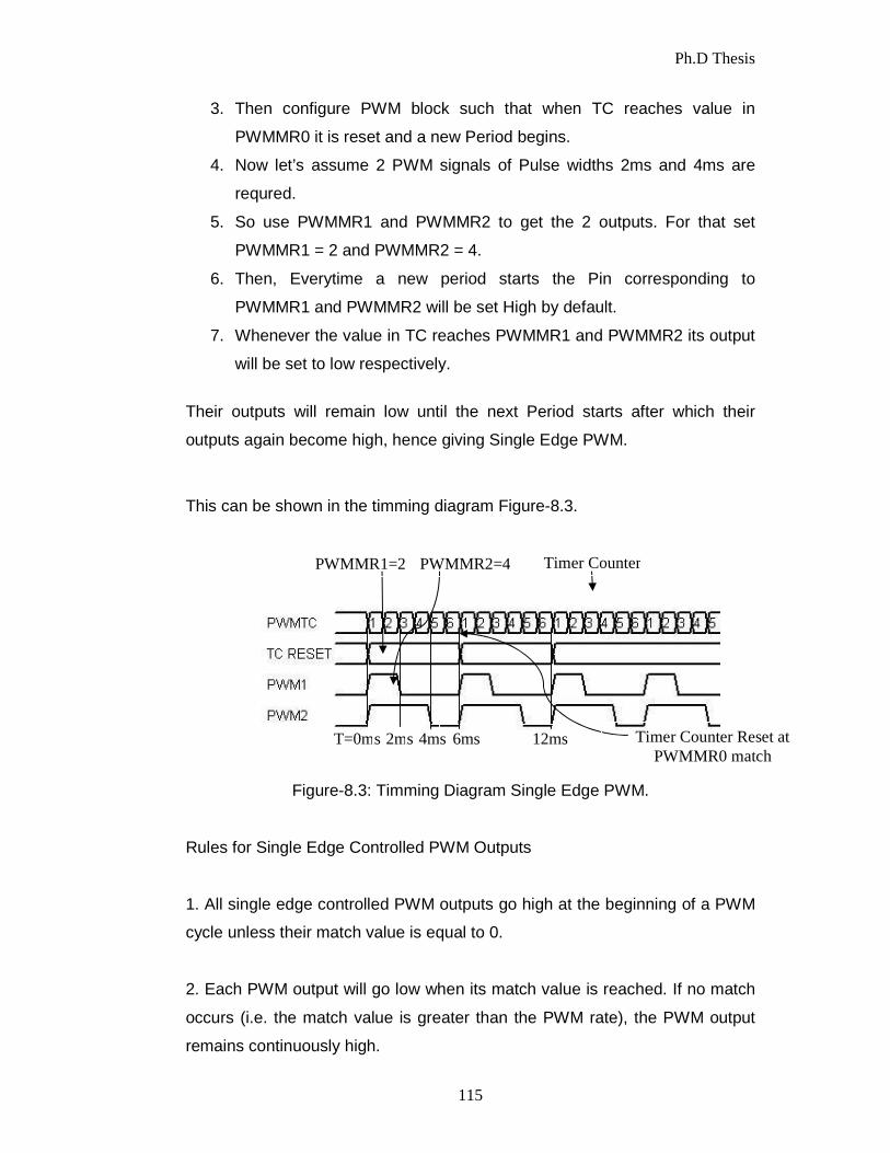
This can be shown in the timming diagram Figure-8.3.
Figure-8.3: Timming Diagram Single Edge PWM.
Rules for Single Edge Controlled PWM Outputs
1. All single edge controlled PWM outputs go high at the beginning of a PWM
cycle unless their match value is equal to 0.
2. Each PWM output will go low when its match value is reached. If no match
occurs (i.e. the match value is greater than the PWM rate), the PWM output
remains continuously high.
PWMMR1=2 PWMMR2=4 Timer Counter
T=0ms 2ms 4ms 6ms 12ms Timer Counter Reset at PWMMR0 match

Ph.D Thesis
116
Rules for Double Edge Controlled PWM Outputs
Five rules are used to determine the next value of a PWM output when a new
cycle is about to begin:
1. The match values for the next PWM cycle are used at the end of a PWM
cycle (a time point which is coincident with the beginning of the next PWM
cycle), except as noted in rule 3.
2. A match value equal to 0 or the current PWM rate (the same as the Match
channel 0 value) has the same effect, except as noted in rule 3. For example,
a request for a falling edge at the beginning of the PWM cycle has the same
effect as a request for a falling edge at the end of a PWM cycle.
3. When match values are changing, if one of the "old" match values is equal
to the PWM rate, it is used again once if the neither of the new match values
are equal to 0 or the PWM rate, nor there was no old match value equal to 0.
4. If both a set and a clear of a PWM output are requested at the same time,
clear takes precedence. This can occur when the set and clear match values
are the same as in, or when the set or clear value equals 0 and the other
value equals the PWM rate.
5. If a match value is out of range (i.e. greater than the PWM rate value), no
match event occurs and that match channel has no effect on the output. This
means that the PWM output will remain always in one state, allowing always
low, always high, or "no change" outputs.
The last 6 Match Registers i.e PWMMR1 to PWMMR6 have an
associated PIN from which we get the PWM outputs. The PWM block controls
the output of these pins depending on the value in its corresponding Match
Register. For Single Edged PWM these Pins are set to High by default when a
new Period starts i.e when TC is reset as per the PWM Rules given above.

Ph.D Thesis
117
Note that the width of the Pulse is stored in the Match Register. One
can change the width of the pulse by changing the value in the corresponding
Match register using a special register called Latch Enable Register which is
used to control the way Match Registers get updated. Some of the important
register in the PWM block is discusses below.
1) PWMTCR: PWM Timer Control Register
This register is used to control the Timer Counter inside the PWM block. Only
Bits: 0, 1 & 3 are used rest are reserverd.
• Bit 0: This bit is used to Enable/Disable Counting. When 1 both PWM
Timer counter and PWM Prescale counter are enabled. When 0 both
are disabled.
• Bit 1: This bit is used to reset both Timer and Prescale counter inside
the PWM block. When set to 1 it will reset both of them (at next edge of
PCLK).
• Bit 3: This is used to enable the PWM mode i.e the PWM outputs.
Other Bits: Reserved.
2) PWMPR: PWM Prescale Register
PWMPR is used to control the resolution of the PWM outputs. The Timer
Counter(TC) will increment every PWMPR+1 Peripheral Clock Cycles (PCLK).
3) PWMMR0 – PWMMR6: Match Registers
These are the seven Match registers as explained above which contain Pulse
Width Values i.e the Number of PWMTC Ticks.
4) PWMMCR: PWM Match Control Registers
The PWM Match Control Register is used to specify what operations can be
done when the value in a particular Match register equals the value in TC. For
each Match Register we have 3 options: Either generate an Interrupt, or
Reset the TC, or Stop, which stops the counters and disables PWM. Hence
Ph.D Thesis
118
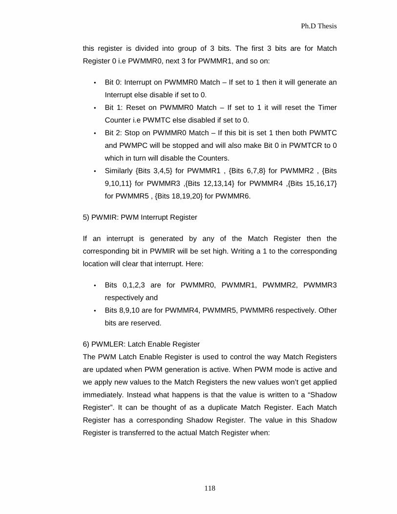
this register is divided into group of 3 bits. The first 3 bits are for Match
Register 0 i.e PWMMR0, next 3 for PWMMR1, and so on:
• Bit 0: Interrupt on PWMMR0 Match – If set to 1 then it will generate an
Interrupt else disable if set to 0.
• Bit 1: Reset on PWMMR0 Match – If set to 1 it will reset the Timer
Counter i.e PWMTC else disabled if set to 0.
• Bit 2: Stop on PWMMR0 Match – If this bit is set 1 then both PWMTC
and PWMPC will be stopped and will also make Bit 0 in PWMTCR to 0
which in turn will disable the Counters.
• Similarly {Bits 3,4,5} for PWMMR1 , {Bits 6,7,8} for PWMMR2 , {Bits
9,10,11} for PWMMR3 ,{Bits 12,13,14} for PWMMR4 ,{Bits 15,16,17}
for PWMMR5 , {Bits 18,19,20} for PWMMR6.
5) PWMIR: PWM Interrupt Register
If an interrupt is generated by any of the Match Register then the
corresponding bit in PWMIR will be set high. Writing a 1 to the corresponding
location will clear that interrupt. Here:
• Bits 0,1,2,3 are for PWMMR0, PWMMR1, PWMMR2, PWMMR3
respectively and
• Bits 8,9,10 are for PWMMR4, PWMMR5, PWMMR6 respectively. Other
bits are reserved.
6) PWMLER: Latch Enable Register
The PWM Latch Enable Register is used to control the way Match Registers
are updated when PWM generation is active. When PWM mode is active and
we apply new values to the Match Registers the new values won’t get applied
immediately. Instead what happens is that the value is written to a “Shadow
Register”. It can be thought of as a duplicate Match Register. Each Match
Register has a corresponding Shadow Register. The value in this Shadow
Register is transferred to the actual Match Register when:

Ph.D Thesis
119
1) PWMTC is reset (i.e at the beginning of the next period).
2) And the corresponding Bit in PWMLER is 1.
Hence only when these 2 conditions are satisfied the value is copied to Match
Register. Bit ‘x’ in PWMLER corresponds to match Register ‘x’. I.e Bit 0 is for
PWMMR0, Bit 1 for PWMMR1, and so on. Using PWMLER will be covered in
the examples section.
7) PWMPCR: PWM Control Register
This register is used for Selecting between Single Edged & Double Edged
outputs and also to Enable/Disable the 6 PWM outputs which go to their
corresponding Pins.
• Bits 2 to 6 are used to select between Single or Double Edge mode for
PWM 2,3,4,5,6 outputs.
a) Bit 2 : If set to 1 then PWM2(i.e the one corresponding to
PWMMR2) output is double edged else if set 0 then its Single
Edged.
b) Similarly {Bits 3,4,5,6} for PWM3 , PWM4 , PWM5 , PWM6
respectively.
• Bits 9 to 14 are used to Enable/Disable PWM outputs.
a) Bit 9: If set to 1 then PWM1 output is enabled, else disabled if
set to 0.
b) Similarly {Bit 10,11,12,13,14} for PWM2 , PWM3 , PWM4,
PWM5 , PWM6 respectively.

Ph.D Thesis
120
Configuring and Initializing PWM
Configuring PWM is very much similar to Configuring Timer except,
additionally, one need to enable the outputs and select PWM functions for the
corresponding PIN on which output will be available. But first we need to do
some basic Math Calculations for defining the Period time, the resolution
using a prescale value and then Pulse Widths. For this First we need to define
the resolution of out PWM signal. Here the PWM resolution is the minimum
increment that can use to increase or decrease the pulse width. Smaller the
increment more fine will be the resolution. This resolution is defined using an
appropriate Prescale Value. The calculation for Prescale is the same as the
Timer given below:
PWM Prescale (PWMPR) Calculations: The delay or time required for ‘Y’ clock cycles of PCLK at ‘X’ MHz is given by:
Taking PR into consideration one get Y = PR+1. Now, consider that PCLK is
running at 60Mhz then X=60. Hence if we use Y=60 i.e PR=59 then we get a
delay of exact 1 micro-second(s).
So with PR=59 and PCLK @ 60Mhz our formula reduces to:
Similarly when, Y=60000 i.e. PR = 59999 the delay will be 1 milli-second(s):

Ph.D Thesis
121
This delay which is defined using Prescale will be the delay required for TC to
increment by 1 i.e TC will increment every ‘PR+1 ′ “Peripheral” Clock
Cycles (PCLK) .
Now, after working out the resolution, one can now Set and Initialize the PWM
device as per the following steps:
1. Select the PWM function for the PIN on which you need the PWM
output using PINSEL0/1 register.
2. Select Single Edge or Double Edge Mode using PWMPCR. By default
it’s Single Edge Mode.
3. Assign the Calculated value to PR.
4. Set the Value for PWM Period in PWMMR0.
5. Set the Values for other Match Registers i.e the Pulse Widths.
6. Set appropriate bit values in PWMMCR. For e.g. resetting PWMTC for
PWMMR0 match and optionally generate interrupts if required.
7. Set Latch Enable Bits for the Match Registers that is to be used.
8. Then Enable PWM outputs using PWMPCR.
9. Now Reset PWM Timer using PWMTCR.
Finally, enable Timer, Counter and PWM Mode using PWMTCR.

Ph.D Thesis
122
8.3 DC Servo Motor and Its Working Principle A servo motor is an electromechanical device in which the electrical input
determines the position of motor armature. It is actually an assembly of four
things: a normal DC motor, a gear reduction unit, a position-sensing device
and a control circuit. Servo motors are used extensively in robotics industry
and radio-controlled cars. DC servo motors are working in a closed loop
control systems where the programmed positions of motion and velocity
feedback controllers are required. A simplest method to control the rotation
speed of a DC motor is to control its driving voltage. The higher the voltage is
the higher speed the motor tries to reach.
Servos are controlled by a pulse of variable width. The sent
signal of this input pulse is characterized by a minimum pulse, maximum, and
a repetition rate as shown in Figure-8.1.
Given the rotation constraints of the servo, neutral is defined to be the position
where the servo has exactly the same amount of potential rotation in a
clockwise direction as it is in a counter clockwise direction.The servo should
detect a pulse every 20 ms. The length of the pulse will determine how far the
motor turns. For example, a 1.5 ms pulse will make the motor turn to a 90
degree position (neutral position). The position pulse must be repeated to
instruct the servo to stay in position.
In many applications, a simple voltage regulation would cause lots of
power loss on control circuit, thus, a pulse width modulation method (PWM) is
used in many DC motor controlling applications. In the basic PWM method,
the operating power to the motors is turned ON and OFF to modulate the
current to the motor. The PWM control method uses the widths of pulses in a
pulse train to control the speed of the motor.
In the presented work Parallex standard servo is used and controlled
using PWM controller based on robot control panel. The specifications of

Ph.D Thesis
123
Parallax standart servo is given below in Table-8.2. Figure-8.4 shows the
different pulse length and Parallax standard servo position.
Power
Requirements
4 to 6V VDC, maximum
current draw is 140 +/-
50mA at 6 VDC when
operating in no load
conditions, 15mA when
in static state
Communication
PWM, 0.75-2.25 ms
high pulse, 20ms
intervals
Dimentions 2.2x0.8x1.6 inch
excluding servo horn
Operating
Temperature
Range
-10 to +50 ˚C
Wieght 44g
Table-8.2: Parallax Standard Servo Specifications.
Figure-8.4: PWM pulse length changes to control servo position.

Ph.D Thesis
124
The mathematical model of DC servo motor can be simplified by means of the
equivalent circuit as shown in the Figure-8.5.
Figure-8.5: DC Servo Motor Equivalent Circuit.
The electrical part represented by armature and the mechanical part by T and
J. As the field excitation is constant, the armature controller only depends on
armature voltage. The mechanical equations describing this system can be
written with the assumptions that the loss is included in load torque and
neglecting viscous friction constant as given below,
With, Eb = Kω and Te = Ki Where i = armeture current, Va = armeture voltage, Ra = armeture resistance,
La = armeture inductance, K = torque and back electromagnetic constant, ω =
rotor angular speed, Te = electromagnetic torque, T = total load torque, J =
rotor inertia.
The control input is the armature voltage Va and the total load torque T is the
disturbing input. The two state variables are armature current i and angular
Ph.D Thesis
125
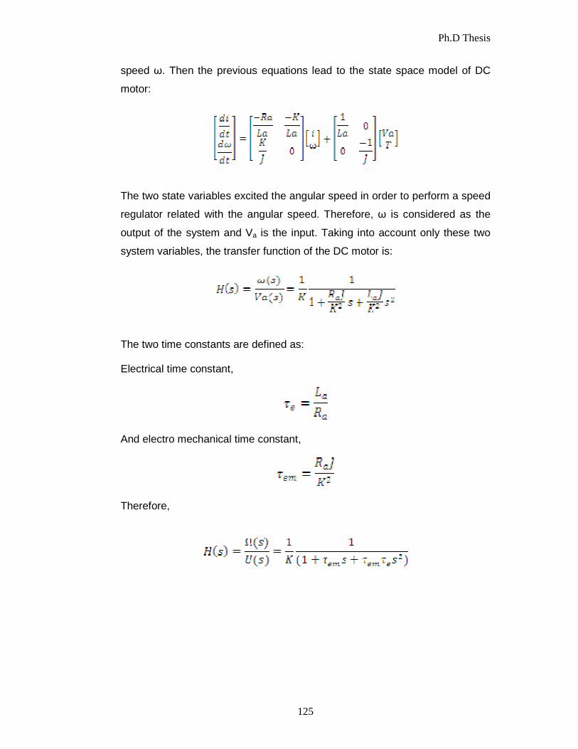
speed ω. Then the previous equations lead to the state space model of DC
motor:
The two state variables excited the angular speed in order to perform a speed
regulator related with the angular speed. Therefore, ω is considered as the
output of the system and Va is the input. Taking into account only these two
system variables, the transfer function of the DC motor is:
The two time constants are defined as: Electrical time constant,
And electro mechanical time constant,
Therefore,

Ph.D Thesis
126
Servo Motor
VCC GND
8.4 Experimental Setup PWM1 output from Pin P0.0 is used to control a RC Servo Motor. Four tactile
switches are also used to bring the Servo at 4 different positions. P0.1, P0.2,
P0.3, P0.4 will be used to take the input from the switches. One end of the
tactile switches will be connected to each of these Pins and other end will be
connected to ground. External 5V-6V supply source to drive the servo. Servos
can work with 3.3v voltage levels for input PWM signal; hence we just need to
connect the MCU PWM Output to Servo PWM Input wire. Figure-8.6 shows
the schametic diagram of PWM controller using ARCB.
When the user will press P1.16 the Pulse width will be 1ms , and similarly
when the user presses P1.17 , P1.18, and P1.19 the Pulse Width will change
to 1.25ms , 1.5ms and 1.75ms respectively and hence Servo will change its
position correspondingly.
Figure-8.6: PWM Controller Schametic.
ARCB l P1.19
P1.18 P1.17P1.16 P0.0
Power Supply
VCC GND
PWM IN
SW2
SW1
SW3
SW4
GND

Ph.D Thesis
127
8.5 Software Implementation The software is written in the Embedded C language using the Keil µvision
IDE. Program for PWM initialization, PLL intialization and PWM generation on
P0.0 pin of robot control panel is self explanatory and is given as below:
#include <lpc213x.h>
#define PLOCK 0x00000400
#define PWMPRESCALE 60
void initPWM(void);
void initClocks(void);
int main(void)
{
initClocks(); //Initialize CPU and Peripheral Clocks @ 60Mhz
initPWM(); //Initialize PWM
while(1)
{
if( !((IO1PIN) & (1<<16)) ) // Check P1.16
{
PWMMR1 = 1000;
PWMLER = (1<<1); //Update Latch Enable bit for PWMMR1
}
else if( !((IO1PIN) & (1<<17)) ) // Check P1.17
{
PWMMR1 = 1250;

Ph.D Thesis
128
PWMLER = (1<<1);
}
else if( !((IO1PIN) & (1<<18)) ) // Check P1.18
{
PWMMR1 = 1500;
PWMLER = (1<<1);
}
else if( !((IO1PIN) & (1<<19)) ) // Check P1.19
{
PWMMR1 = 1750;
PWMLER = (1<<1);
}
}
}
void initPWM(void)
{
PINSEL0 = (1<<1); // Select PWM1 output for Pin0.0
PWMPCR = 0x0; //Select Single Edge PWM
PWMPR = PWMPRESCALE-1; // 1 micro-second resolution
PWMMR0 = 20000; // 20ms = 20k us - period duration
PWMMR1 = 1000; // 1ms - pulse duration i.e width
PWMMCR = (1<<1); // Reset PWMTC on PWMMR0 match
PWMLER = (1<<1) | (1<<0); // update MR0 and MR1

Ph.D Thesis
129
PWMPCR = (1<<9); // enable PWM output
PWMTCR = (1<<1); //Reset PWM TC & PR
PWMTCR = (1<<0) | (1<<3); // enable counters and PWM Mode
}
void initClocks(void)
{
PLLCON = 0x01; // PPLE=1 & PPLC=0 so it will be enabled
PLLCFG = 0x24; // set the multipler to 5 (i.e actually 4)
// i.e 12x5 = 60 Mhz (M - 1 = 4)
// Set P=2 since we want FCCO in range
PLLFEED = 0xAA;
PLLFEED = 0x55;
while( !( PLLSTAT & PLOCK ));
PLLCON = 0x03;
PLLFEED = 0xAA;
PLLFEED = 0x55;
VPBDIV = 0x01; // PCLK is same as CCLK i.e 60Mhz
}

Ph.D Thesis
130
8.6 Results and Conclusion The simulation is used to validate the results obtained from Keil µvision4 logic
analyzer during debug session. Figure-8.7 shows the different PWM signals
generated in the logic analyzer screen which is the required pulse to drive the
DC servo motor.
(a) Pulse width 1ms, P1.16 pressed.
(b) Pulse width 1.25ms, P1.17 pressed

Ph.D Thesis
131
(c) Pulse width 1.50ms, P1.18 pressed.
(d) Pulse width 1.75ms, P1.19 pressed
Figure-8.7: PWM Signals on PWM1 The actual setup for PWM controller using LPC2138 based robot control
panel to drive servo motor is shown in Figure-8.8.

Ph.D Thesis
132
Figure-8.8: PWM Controller Actual Experimental Setup. This chapter provides the design and development of PWM controller based
on ARCB to run DC servo motor. The design can be extended upto six PWM
channels. Simulation results on the Keil IDE have proven its correctness and
usefullness.