chapter 8 inorg
DESCRIPTION
Chapter 8 InorgTRANSCRIPT
Chapter 8 Chemistry of the Main Group Elements 107
Copyright © 2014 Pearson Education, Inc.
CHAPTER 8: CHEMISTRY OF THE MAIN GROUP ELEMENTS 8.1 a. H2 74.2 pm 436 kJ/mol H2
+ 106 pm 255 kJ/mol
These values are consistent with the molecular orbital descriptions. H2 has two electrons in the bonding orbital, H2
+ has only one. The net attraction between the bonding electron and the nuclei are weaker in H2
+ relative to that between the two bonding electrons and the nuclei in H2.Therefore, the bond distance is longer in H2
+.
b. H3+ was described in Problems 5.21 and 5.43. It has a single pair of electrons in a
2-electron, 3-center bond, with bond orders of 1/3.
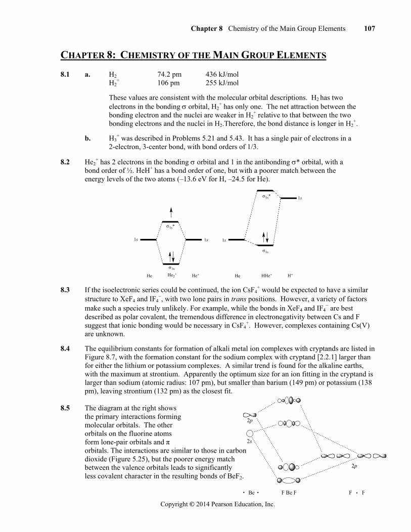
8.2 He2+ has 2 electrons in the bonding orbital and 1 in the antibonding * orbital, with a
bond order of ½. HeH+ has a bond order of one, but with a poorer match between the energy levels of the two atoms (–13.6 eV for H, –24.5 for He).
HeHe2+He He+ H+
1s 1s 1s
1s
HHe+
1s*
1s*
1s
1s
8.3 If the isoelectronic series could be continued, the ion CsF4+ would be expected to have a similar
structure to XeF4 and IF4–, with two lone pairs in trans positions. However, a variety of factors
make such a species truly unlikely. For example, while the bonds in XeF4 and IF4– are best
described as polar covalent, the tremendous difference in electronegativity between Cs and F suggest that ionic bonding would be necessary in CsF4
+. However, complexes containing Cs(V) are unknown.
8.4 The equilibrium constants for formation of alkali metal ion complexes with cryptands are listed in Figure 8.7, with the formation constant for the sodium complex with cryptand [2.2.1] larger than for either the lithium or potassium complexes. A similar trend is found for the alkaline earths, with the maximum at strontium. Apparently the optimum size for an ion fitting in the cryptand is larger than sodium (atomic radius: 107 pm), but smaller than barium (149 pm) or potassium (138 pm), leaving strontium (132 pm) as the closest fit.
8.5 The diagram at the right shows the primary interactions forming molecular orbitals. The other
orbitals on the fluorine atoms form lone-pair orbitals and π orbitals. The interactions are similar to those in carbon dioxide (Figure 5.25), but the poorer energy match between the valence orbitals leads to significantly less covalent character in the resulting bonds of BeF2.
Be F Be F F F
2p
2p
2s
108 Chapter 8 Chemistry of the Main Group Elements
Copyright © 2014 Pearson Education, Inc.
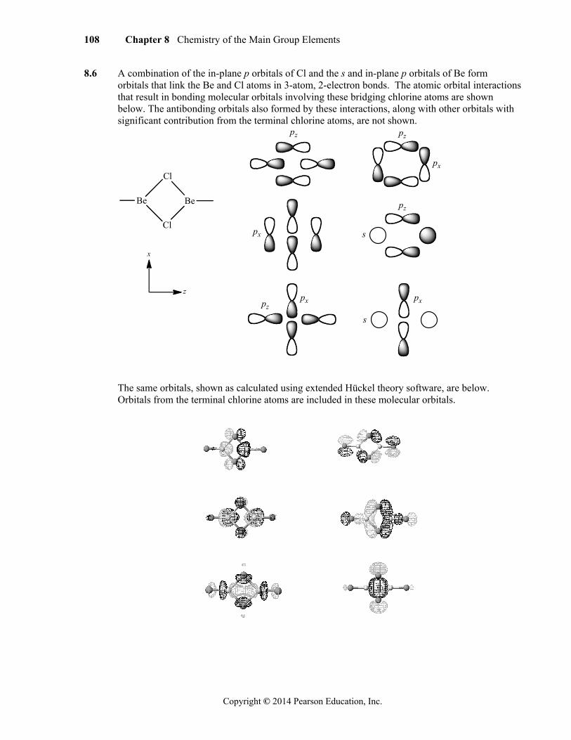
8.6 A combination of the in-plane p orbitals of Cl and the s and in-plane p orbitals of Be form orbitals that link the Be and Cl atoms in 3-atom, 2-electron bonds. The atomic orbital interactions that result in bonding molecular orbitals involving these bridging chlorine atoms are shown below. The antibonding orbitals also formed by these interactions, along with other orbitals with significant contribution from the terminal chlorine atoms, are not shown.
Be
Cl
Cl
Be
z
x
pz pz
pz
pz
px
px
px px
s
s
The same orbitals, shown as calculated using extended Hückel theory software, are below. Orbitals from the terminal chlorine atoms are included in these molecular orbitals.
Chapter 8 Chemistry of the Main Group Elements 109
Copyright © 2014 Pearson Education, Inc.
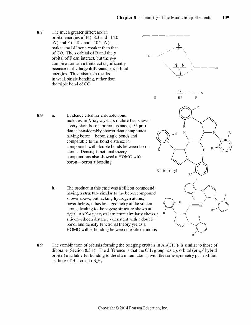
8.7 The much greater difference in orbital energies of B (–8.3 and –14.0 eV) and F (–18.7 and –40.2 eV) makes the BF bond weaker than that of CO. The s orbital of B and the p orbital of F can interact, but the p-p combination cannot interact significantly
because of the large difference in p orbital energies. This mismatch results
in weak single bonding, rather than the triple bond of CO. 8.8 a. Evidence cited for a double bond
includes an X-ray crystal structure that shows a very short boron–boron distance (156 pm) that is considerably shorter than compounds having boron—boron single bonds and comparable to the bond distance in compounds with double bonds between boron atoms. Density functional theory computations also showed a HOMO with boron—boron π bonding.
b. The product in this case was a silicon compound
having a structure similar to the boron compound shown above, but lacking hydrogen atoms; nevertheless, it has bent geometry at the silicon atoms, leading to the zigzag structure shown at right. An X-ray crystal structure similarly shows a silicon–silicon distance consistent with a double bond, and density functional theory yields a HOMO with π bonding between the silicon atoms.
8.9 The combination of orbitals forming the bridging orbitals in Al2(CH3)6 is similar to those of diborane (Section 8.5.1). The difference is that the CH3 group has a p orbital (or sp3 hybrid orbital) available for bonding to the aluminum atoms, with the same symmetry possibilities as those of H atoms in B2H6.
B B
H
H
N
N
N
N
R
R
R
R
R
RR
R
R = isopropyl
2s
2s
B BF F
2p
2p
Si Si
N
N
N
N
R
RR
R
R
R
R
R

110 Chapter 8 Chemistry of the Main Group Elements
Copyright © 2014 Pearson Education, Inc.
8.10 D2h E C2(z) C2(y) C2(x) i (xy) (xz) (yz)
(pz) 2 2 0 0 0 0 2 2
(px) 2 –2 0 0 0 0 2 –2
(1s) 2 0 0 2 0 2 2 0 Ag 1 1 1 1 1 1 1 1 z2
B2g 1 –1 1 –1 1 –1 1 –1 xz B1u 1 1 –1 –1 –1 –1 1 1 xy B3u 1 –1 –1 1 –1 1 1 –1 x
Reduction of the representations gives the following: Boron orbitals: a. (pz) = Ag + B1u
b. (px) = B2g + B3u
Hydrogen orbitals: c. (1s) = Ag + B3u d. Treating each group orbital as a single orbital, the orbitals below have the indicated symmetries.
D2h E C2(z) C2(z) C2(z) i (xy) (xz) (yz) Ag (pz) 1 1 1 1 1 1 1 1 B1u (pz) 1 1 –1 –1 –1 –1 1 1
B2g(px)
1
–1
1
–1
1
–1
1
–1
B3u (px)
1
–1
–1
1
–1
1
1
–1
Ag (s)
1
1
1
1
1
1
1
1
B3u
1
–1
–1
1
–1
1
1
–1
8.11 Carbon has two lone pairs in C(PPh3)2, with VSEPR predicting a tetrahedral electron group
geometry. The bulky phenyl groups limit the impact of the nonbonding pairs and force a larger angle.
Chapter 8 Chemistry of the Main Group Elements 111
Copyright © 2014 Pearson Education, Inc.
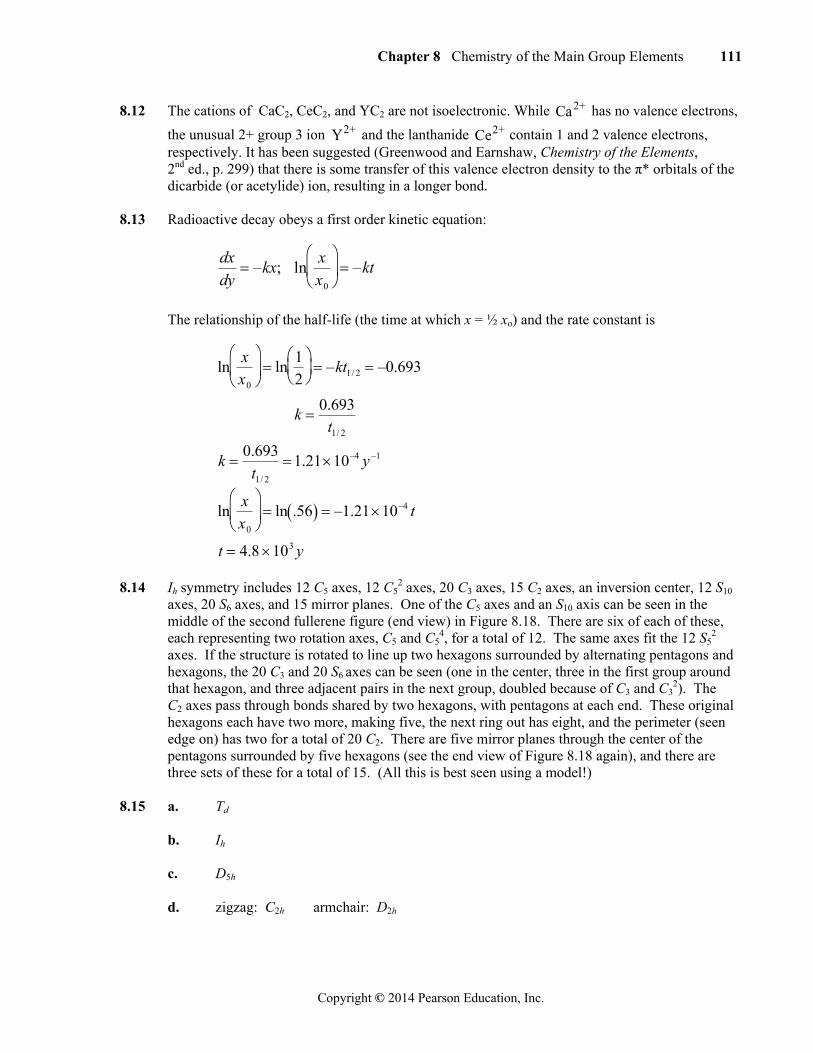
8.12 The cations of CaC2, CeC2, and YC2 are not isoelectronic. While Ca2+ has no valence electrons,
the unusual 2+ group 3 ion Y2+ and the lanthanide Ce2+ contain 1 and 2 valence electrons, respectively. It has been suggested (Greenwood and Earnshaw, Chemistry of the Elements,
2nd ed., p. 299) that there is some transfer of this valence electron density to the π* orbitals of the dicarbide (or acetylide) ion, resulting in a longer bond. 8.13 Radioactive decay obeys a first order kinetic equation:
dx
dy –kx; ln
x
x0
–kt
The relationship of the half-life (the time at which x = ½ xo) and the rate constant is
lnx
x0
ln
1
2
–kt1/ 2 –0.693
k 0.693t1/ 2
k 0.693
t1/ 2
1.2110–4 y –1
lnx
x0
ln .56 –1.2110–4 t
t 4.8 103 y
8.14 Ih symmetry includes 12 C5 axes, 12 C5
2 axes, 20 C3 axes, 15 C2 axes, an inversion center, 12 S10 axes, 20 S6 axes, and 15 mirror planes. One of the C5 axes and an S10 axis can be seen in the middle of the second fullerene figure (end view) in Figure 8.18. There are six of each of these, each representing two rotation axes, C5 and C5
4, for a total of 12. The same axes fit the 12 S52
axes. If the structure is rotated to line up two hexagons surrounded by alternating pentagons and hexagons, the 20 C3 and 20 S6 axes can be seen (one in the center, three in the first group around that hexagon, and three adjacent pairs in the next group, doubled because of C3 and C3
2). The C2 axes pass through bonds shared by two hexagons, with pentagons at each end. These original
hexagons each have two more, making five, the next ring out has eight, and the perimeter (seen edge on) has two for a total of 20 C2. There are five mirror planes through the center of the pentagons surrounded by five hexagons (see the end view of Figure 8.18 again), and there are three sets of these for a total of 15. (All this is best seen using a model!)
8.15 a. Td b. Ih c. D5h d. zigzag: C2h armchair: D2h
112 Chapter 8 Chemistry of the Main Group Elements
Copyright © 2014 Pearson Education, Inc.
8.16 Graphane, obtained from the hydrogenation of graphene, was first reported in 2009 (see J. Agbenyega, Mater. Today, 2009, 12, 13), and research interest has grown rapidly.
8.17 Printing on transparencies is suggested for this exercise. Rolling up of the diagram should
show that more than one chiral form is possible.
8.18 Readers are encouraged to search for the most recent references in this promising area. At this writing (February 2013) the reference has been cited in 176 other articles in scientific journals.
8.19 The reference provides absorption spectra and colors of solutions containing mixtures of armchair-enriched single-walled carbon nanotubes with different diameters, ranging from 0.83 nm to 1.5 nm. The strongest absorption band for the nanotubes shifted to longer wavelength (lower energy) as the diameter increased, with the smallest absorbing at 407 nm and the largest at 785 nm, and the observed colors (complementary to the colors of the strongest absorption bands) changed accordingly. The observations were consistent with the energy levels of the nanotubes becoming closer as the diameters of the tubes increased. A similar size effect is observed for quantum dots (Section 7.3.2).
8.20 The increased stability of 2+ oxidation states as compared to 4+ is an example of the “inert pair” effect (see Greenwood and Earnshaw, Chemistry of the Elements, 2nd ed., pp. 226, 227, 374). In general, the ionization energy decreases going down a column of the periodic table, because of greater shielding by the inner electrons. In this family, removal of the second electron is fairly easy, as it is the first in the higher-energy p orbitals. However, the next two electrons to be removed are the s electrons, and they are not as thoroughly shielded in the ions. The effect is larger for the three lower members of the group because the d10 electrons are added between the s and p electrons. The lower electronegativity of C and Si make them more likely to form covalent bonds than ions.
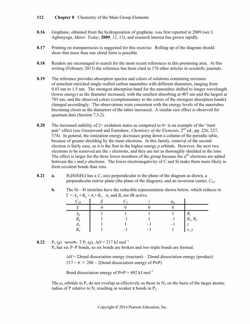
8.21 a. H2ISiSiH2I has a C2 axis perpendicular to the plane of the diagram as drawn, a perpendicular mirror plane (the plane of the diagram), and an inversion center, C2h.
b. The Si—H stretches have the reducible representation shown below, which reduces to = Ag +Bg +Au+Bu. Au and Bu are IR-active. 8.22 P4 (g) 2 P2 (g), H = 217 kJ mol–1
P4 has six P–P bonds, so six bonds are broken and two triple bonds are formed.
H = bond dissociation energy (reactant) – bond dissociation energy (product) 217 = 6 × 200 – 2(bond dissociation energy of PP)
Bond dissociation energy of PP = 492 kJ mol–1
The pπ orbitals in P2 do not overlap as effectively as those in N2 on the basis of the larger atomic radius of P relative to N, resulting in weaker π bonds in P2.
C2h E C2 i h
4 0 0 0 Ag 1 1 1 1 Rz
Bg 1 –1 1 –1 Rx, Ry
Au 1 1 –1 –1 z Bu 1 –1 –1 1 x, y

Chapter 8 Chemistry of the Main Group Elements 113
Copyright © 2014 Pearson Education, Inc.
8.23 a. N3– has molecular orbitals similar to those of CO2 (Section
5.4.2), with two occupied orbitals and two occupied π orbitals for a total of four bonds. In contrast to the situation in CO2 , the atomic orbitals involved in the bonding in N3
– have equal energies.
b. Because the HOMOs of N3– (at right) are primarily
composed of p orbitals of the terminal nitrogen atoms, H+ bonds at an angle to the N=N=N axis. The angle is 114°, larger than the 90° predicted by simple bonding to a p orbital.
c. The H–N–N angle is 114º. This observation suggests that
the first resonance structure (with an N(sp)—H bond) contributes less to the electronic ground state of HN3 relative to the second structure (with an N(sp3)—H bond. A decreased terminal N—N distance relative to the central N—N distance is consistent with these contributions.
8.24 The electronegativity of H (2.300) is less than that of N (3.066). Hydrazine has two hydrogen
atoms and an equally electronegative NH2 group bound to each nitrogen atom, while ammonia has three hydrogens bound to N. In this way, ammonia features three polar covalent bonds enriching the electron density at nitrogen, while hydrazine features two polar covalent N—H bonds and one nonpolar covalent bond (to the NH2 group). The N of ammonia is therefore more electron-rich, and hydrazine is the weaker aqueous base.
Another factor is the potential for hydrogen bonding with water in the resulting conjugate acids. An ammonium ion (NH4
+) features four excellent hydrogen bond donors per N atom, while hydrazinium ion features just three hydrogen atoms bound to a positively charged N atom. The enhanced opportunities for NH4
+ solvation relative to N2H5+ contribute to NH3 being a stronger
base.
8.25 The larger central atoms feature longer bond lengths, leading to lower concentrations of bonding electron density close to the Group 15 atom, reducing bonding pair-bonding pair repulsion. The lone pair subsequently exerts increasing influence down the column, forcing smaller angles as the atomic radius of the central atom increases. This decrease in bonding pair-bonding pair repulsion can also be explained using electronegativity arguments, with the most electronegative nitrogen atom drawing a larger share of the bonding electron density towards it relative to the other group 15 elements that progressively become less electronegative down the column.
8.26 One p orbital of each oxygen is used for the bond to nitrogen, and the p orbital perpendicular to the plane of the molecule is used for a π orbital. The remaining p orbital is in the plane of the molecule, so addition of a proton to this lone pair leaves the entire molecule planar.
8.27 From Table 8.10 N2O Cv NO Cv NO2 C2v N2O3 Cs N2O4 D2h N2O5 D2h NO+ Cv NO2
+ Dh
NO2– C2v NO3
– D3h N2O22– C2h NO4
3– Td
HNO2 Cs HNO3 Cs
n
*
NH N N
NH N N
1+ 1+
1+1–
2–
114 Chapter 8 Chemistry of the Main Group Elements
Copyright © 2014 Pearson Education, Inc.
8.28 a. Computational work suggests that the electronic ground state of cis- N2F4 is 1.4 kcal/mol
lower than that of trans- N2F4 at 298 K.
b. Two trans-cis isomerization mechanisms are proposed. The simpler mechanistic possibility involves rotation about the N=N bond. A lower limit of 59.6 kcal/mol was calculated for this isomerization mechanism. The second possibility proceeds via a planar transition state that resembles [N2F]F , with relatively short and long N—F bonds, and a
nitrogen–nitrogen triple bond, respectively. The transformation of nitrogen–nitrogen bonding electron density to nonbonding electron density at nitrogen completes the isomerization. An activation barrier of 68.7 kcal/mol was determined for this mechanism. The activation barrier for isomerization via N=N rotation is 9.1 kcal/mol less than the proposed barrier for the [N2F]F mechanism.
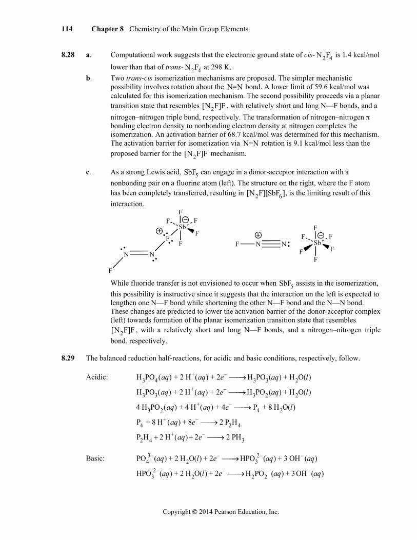
c. As a strong Lewis acid, SbF5 can engage in a donor-acceptor interaction with a
nonbonding pair on a fluorine atom (left). The structure on the right, where the F atom has been completely transferred, resulting in [N2F][SbF6], is the limiting result of this
interaction.
N
F
N
F
SbF
FF
F
F NF NF
SbF
FF
F
F
While fluoride transfer is not envisioned to occur when SbF5 assists in the isomerization,
this possibility is instructive since it suggests that the interaction on the left is expected to lengthen one N—F bond while shortening the other N—F bond and the N—N bond. These changes are predicted to lower the activation barrier of the donor-acceptor complex (left) towards formation of the planar isomerization transition state that resembles [N2F]F , with a relatively short and long N—F bonds, and a nitrogen–nitrogen triple
bond, respectively. 8.29 The balanced reduction half-reactions, for acidic and basic conditions, respectively, follow.
Acidic: H3PO4(aq) + 2 H+(aq) + 2e– H3PO3(aq) + H2O(l)
H3PO3(aq) + 2 H+(aq) + 2e– H3PO2(aq) + H2O(l)
4 H3PO2(aq) + 4 H+(aq) + 4e– P4 + 8 H2O(l)
P4 + 8 H+ (aq) + 8e– 2 P2H4
P2H4 2 H+(aq) 2e– 2 PH3
Basic: PO43– (aq) + 2 H2O(l) + 2e– HPO3
2– (aq) + 3 OH– (aq)
HPO32– (aq) + 2 H2O(l) + 2e– H2PO2
– (aq) + 3OH– (aq)

Chapter 8 Chemistry of the Main Group Elements 115
Copyright © 2014 Pearson Education, Inc.
4 H2PO2– (aq) + 4e– P4 + 8 OH– (aq)
P4 + 12 H2O(l) + 12e– 4 PH3 + 12 OH– (aq)
The Frost diagram for phosphorus in acidic solution features points at (5, –1.915; H3PO4),
(3, –1.363; H3PO3), (1, –0.365; H3PO2), (0, 0; P4 ), (–2, 0.200; P2H4), and (–3, 0.206; PH3).
The Frost diagram for phosphorus in basic solution features points at (5, –7.43; PO43– ),
(3, –5.19; HPO32–), (1, –2.05; H2PO2
– ), (0, 0; P4 ), (–3, 2.67; PH3).
8.30 The bonding between O2 units is proposed to
involve interactions between the singly occupied π* orbitals of neighboring molecules. Such interactions would generate both bonding and antibonding molecular orbitals, with the
π* π*

116 Chapter 8 Chemistry of the Main Group Elements
Copyright © 2014 Pearson Education, Inc.
originally unpaired π* electrons stabilized (i.e., lowered in energy) as they occupy the bonding orbitals in O8. One such interaction is shown at right. Diagrams of the four highest occupied molecular orbitals of O8 (which may be viewed as (O2) 4) are in the reference.
8.31 S2 is similar to O2, with a double bond. As a result, the bond is shorter than single bonds in S8. 8.32 MnF6
2– acts as a Lewis base, transferring two F– ions to two SbF5 molecules:
MnF62– + 2 SbF5 2 SbF6
– + MnF4
The MnF4 intermediate can then lose an F atom, with two of these radicals coupling to form F2:
2 MnF4 F2 + 2 MnF3
8.33 a. Although the ClO3 groups in Cl2O7 are highly electronegative, their size is apparently
responsible for the larger angle in Cl2O7 (118.6°) than in Cl2O (110.9°).
O
Cl Cl110.9°
O
O3Cl ClO3118.6°
O
O3Cr CrO3126°
2-
b. In the dichromate ion the highly electropositive Cr atoms allow the central oxygen
to attract electrons more strongly than is possible in Cl2O7, resulting in stronger bonding pair-bonding pair repulsions around the central oxygen in [Cr2O7]
2– and a larger bond angle (126°).
8.34 I3
– is linear because there are three lone pairs in a trigonal geometry on the central I. I3+ is
bent because there are only two lone pairs on the central I.
8.35 B has only three valence electrons. Adding six from the hydrogen atoms gives B2H6 a total of 12 electrons. The 3-center 2-electron bonds result in four pairs around each boron atom and nearly tetrahedral symmetry at each boron atom. Iodine has seven valence electrons initially. In I2Cl6, five more are added to each iodine, resulting in 12 electrons and octahedral
geometry around each iodine. 8.36 F– + BrF3 BrF4
– KF acts as a base; BrF4– is the solvent anion.
SbF5 + BrF3 BrF2+ + SbF6
– BrF2+
is the cation of the solvent; SbF5 acts as the acid. 8.37 a. Br2
+ and I2+ have one less antibonding electron than Br2 and I2, so the cations have bond
orders of 1.5 and shorter bonds than the neutral molecules:
Bond Order Bond Distance (pm) Bond Order Bond distance (pm) Br2 1.0 228 I2 1.0 267 Br2
+ 1.5 213 I2+ 1.5 256
b. The most likely transition is from the πg* (HOMO) to u* (LUMO) (see Figure 5.7 for
comparable energy levels of F2). Because the observed colors are complementary to the colors absorbed, Br2
+ is expected to absorb primarily green light, and I2+ is expected to
absorb primarily orange light. Because orange light is less energetic than green, I2+ has
ICl
ClI
Cl
ClI
Cl
Cl
Chapter 8 Chemistry of the Main Group Elements 117
Copyright © 2014 Pearson Education, Inc.
the more closely spaced HOMO and LUMO. c. In both I2 and I2
+ the HOMO and LUMO are the πg* and u*, respectively. I2 absorbs primarily yellow light (to give the observed violet color) and I2
+ absorbs primarily orange (to give blue). Because yellow light is more energetic than orange, I2 has the more widely spaced HOMO and LUMO.
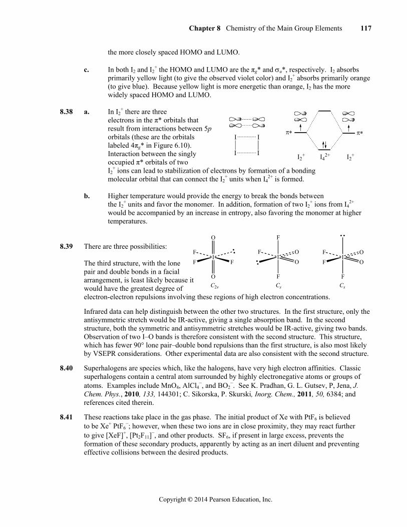
8.38 a. In I2
+ there are three electrons in the π* orbitals that result from interactions between 5p orbitals (these are the orbitals labeled 4πg* in Figure 6.10). Interaction between the singly occupied π* orbitals of two I2
+ ions can lead to stabilization of electrons by formation of a bonding molecular orbital that can connect the I2
+ units when I42+ is formed.
b. Higher temperature would provide the energy to break the bonds between
the I2+ units and favor the monomer. In addition, formation of two I2
+ ions from I42+
would be accompanied by an increase in entropy, also favoring the monomer at higher temperatures.
8.39 There are three possibilities: The third structure, with the lone
pair and double bonds in a facial arrangement, is least likely because it would have the greatest degree of electron-electron repulsions involving these regions of high electron concentrations.
Infrared data can help distinguish between the other two structures. In the first structure, only the antisymmetric stretch would be IR-active, giving a single absorption band. In the second structure, both the symmetric and antisymmetric stretches would be IR-active, giving two bands. Observation of two I–O bands is therefore consistent with the second structure. This structure, which has fewer 90° lone pair–double bond repulsions than the first structure, is also most likely by VSEPR considerations. Other experimental data are also consistent with the second structure.
8.40 Superhalogens are species which, like the halogens, have very high electron affinities. Classic superhalogens contain a central atom surrounded by highly electronegative atoms or groups of atoms. Examples include MnO4, AlCl4
–, and BO2–. See K. Pradhan, G. L. Gutsev, P, Jena, J.
Chem. Phys., 2010, 133, 144301; C. Sikorska, P. Skurski, Inorg. Chem., 2011, 50, 6384; and references cited therein.
8.41 These reactions take place in the gas phase. The initial product of Xe with PtF6 is believed to be Xe+ PtF6
–; however, when these two ions are in close proximity, they may react further to give [XeF]+, [Pt2F11]
–, and other products. SF6, if present in large excess, prevents the formation of these secondary products, apparently by acting as an inert diluent and preventing effective collisions between the desired products.
I
I
I
I
I2+ I4
2+ I2+
I
O
O
F F
FI
F
F
O
F OI
F
F O
F O
C2v Cs Cs

118 Chapter 8 Chemistry of the Main Group Elements
Copyright © 2014 Pearson Education, Inc.
8.42 8.43 Two electrons are in the bonding orbital and two are in the nonbonding orbital:
5p
2p
Xe F Xe F F F 8.44 Xe(OTeF5)4: The OTeF5 group has one electron available for bonding on the O, so the four groups form a square planar structure around Xe, with lone pairs in the axial positions.
O=Xe(OTeF5)4: A square pyramidal structure, with O in one of the axial positions and a lone pair on the other, and OTeF5 groups in the square base. 8.45 Half reactions: Mn2+ + 4 H2O MnO4
– + 8 H+ + 5e– XeO6
4– + 12 H+ + 8e– Xe + 6 H2O Overall reaction: 8 Mn2+ + 5 XeO6
4– + 2 H2O 8 MnO4– + 4 H+ + 5 Xe
8.46 XeF5
– has D5h symmetry. The reducible representation for Xe–F stretching is
D5h E 2C5 2C52 5C2 h 2S5 2S5
3 5v 5 0 0 1 5 0 0 1
which reduces to A1+ E1+ E2, with only E1 IR-active.
XeO
O
F
F
Xe
F
F
XeO
OO
F
F
O
C2vC2v D3h
Xe
O
F F
F F
C4v
Xe
O
F F
F F
Chapter 8 Chemistry of the Main Group Elements 119
Copyright © 2014 Pearson Education, Inc.
8.47 a. Point group: C4v
C4v E 2C4 C2 2v 2d
18 2 –2 4 2 A1 1 1 1 1 1 z A2 1 1 1 –1 –1 Rz B1 1 –1 1 1 –1 B2 1 –1 1 –1 1 E 2 0 –2 0 0 (x, y), (Rx, Ry)
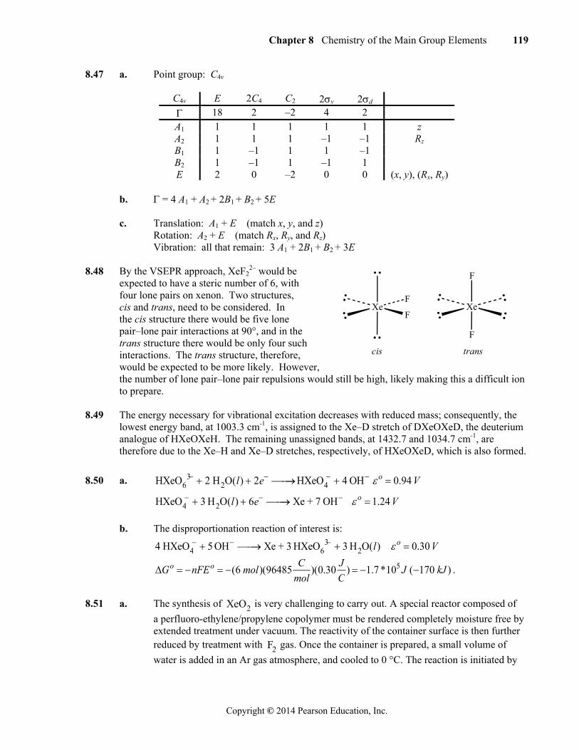
b. = 4 A1 + A2 + 2B1 + B2 + 5E c. Translation: A1 + E (match x, y, and z) Rotation: A2 + E (match Rx, Ry, and Rz) Vibration: all that remain: 3 A1 + 2B1 + B2 + 3E 8.48 By the VSEPR approach, XeF2
2– would be expected to have a steric number of 6, with four lone pairs on xenon. Two structures, cis and trans, need to be considered. In the cis structure there would be five lone pair–lone pair interactions at 90°, and in the trans structure there would be only four such interactions. The trans structure, therefore, would be expected to be more likely. However, the number of lone pair–lone pair repulsions would still be high, likely making this a difficult ion to prepare.
8.49 The energy necessary for vibrational excitation decreases with reduced mass; consequently, the lowest energy band, at 1003.3 cm-1, is assigned to the Xe–D stretch of DXeOXeD, the deuterium analogue of HXeOXeH. The remaining unassigned bands, at 1432.7 and 1034.7 cm-1, are therefore due to the Xe–H and Xe–D stretches, respectively, of HXeOXeD, which is also formed.
8.50 a. HXeO63 2 H2O(l) 2e HXeO4
4 OH o 0.94 V
HXeO4 3 H2O(l) 6e Xe + 7 OH o 1.24 V
b. The disproportionation reaction of interest is:
4 HXeO4 5 OH Xe + 3 HXeO6
3 3 H2O(l) o 0.30 V
Go nFEo (6 mol)(96485C
mol)(0.30
J
C) 1.7 *105 J (170 kJ ) .
8.51 a. The synthesis of XeO2 is very challenging to carry out. A special reactor composed of
a perfluoro-ethylene/propylene copolymer must be rendered completely moisture free by extended treatment under vacuum. The reactivity of the container surface is then further reduced by treatment with F2 gas. Once the container is prepared, a small volume of
water is added in an Ar gas atmosphere, and cooled to 0 °C. The reaction is initiated by
XeF
FXe
F
F
cis trans
120 Chapter 8 Chemistry of the Main Group Elements
Copyright © 2014 Pearson Education, Inc.
slowly adding XeF4 crystals. The authors emphasize the importance of both the order of
the addition (water first, then XeF4 ) and the speed of addition. The large and negative
reaction H , coupled with the relatively small volume of solvent to dissipate the heat, can result in complications, including decomposition of the product; the mixture must be kept at 0 °C. Within 30 seconds after mixing, yellow XeO2precipitates from the
solution. The XeO2solid is then separated from the reaction mixture via centrifugation
of the mini-reactor itself at 0 °C. The resulting solid is thermally unstable at ambient temperature and must be kept cold (-78 °C) for long-term storage.
b. VSEPR theory predicts monomeric XeO2 to be a bent molecule with a persistent dipole
moment that should permit solubility in water. The insolubility of obtained XeO2
samples suggests an extended XeO2 structure; individual monomeric units apparently do
not persist in water. c. Application of isotopically labeled water in the synthesis facilitated XeO2
characterization. The presence of exclusively Xe O bonding was inferred by preparing
XeO2 as described in (a) using H216O and H2
18O, respectively. The Raman spectrum of
the H216O -derived XeO2 was identical to that of the H2
18O-derived XeO2 sample,
except that all of the bands of the H216O -derived XeO2 sample were shifted to slightly
higher energies. The identical spectral patterns, coupled with an isotopic shift in each band, suggested that only Xe O bonding was present. Identical Raman spectra were
obtained for XeO2 samples prepared with either H216O or D2
16O, suggesting no
hydrogen in the samples; no isotopic shifts of any Raman bands were observed. These chemists were particularly interested in the possibility of Xe OH units, which was ruled out by the previous observations.
8.52 a. The [XeF]+ ion, with a total of 14 valence s and p electrons, would be expected to have a
bond order of 1 (see Section 5.2.1).
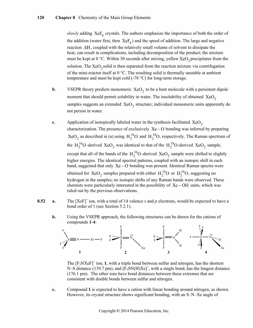
b. Using the VSEPR approach, the following structures can be drawn for the cations of compounds 1-4:
S
F
N Xe F
FF
1
S
F
N
Xe
FF
F
2
S
F
N
H
FF
F
H
3
S
F
N
XeF
F
FH
F
4 The [F3NXeF]+ ion, 1, with a triple bond between sulfur and nitrogen, has the shortest
N–S distance (139.7 pm), and [F5SN(H)Xe]+, with a single bond, has the longest distance (176.1 pm). The other ions have bond distances between these extremes that are consistent with double bonds between sulfur and nitrogen.
c. Compound 1 is expected to have a cation with linear bonding around nitrogen, as shown.
However, its crystal structure shows significant bending, with an S–N–Xe angle of
Chapter 8 Chemistry of the Main Group Elements 121
Copyright © 2014 Pearson Education, Inc.
142.6°. This bending is attributed to close N…F contacts within the crystalline lattice.
d. VSEPR would predict linear bonding with three lone pairs on xenon as, for example, in XeF2. The angle measured by X-ray crystallography is 179.6°.
e. With significant S–N double bonding, these groups are equatorial.
f. The S–Faxial bonds are longer, as in many other VSEPR examples (see Figures 3.17
through 3.19). Average distances for these ions are: (2: S–F (axial), 158.2 pm; S–F (equatorial), 152.4 pm) and (3: S–F (axial), 156.1 pm; S–F (equatorial), 151.8 pm).
8.53 a. D
2h c. C
1 e. C
s
b. D4d
d. C2v
f. C2
8.54 [FBeNe]+ The relative order of molecular orbitals may vary depending on the software used. A
simple approach, using an extended Hückel calculation, gave the following results:
F–Be bonding Several orbitals involved:
HOMO: degenerate pair π bonding between Be and F
Next orbital below HOMO bonding by the F pz and the Be s
Be–Ne bonding One molecular orbital contributing significantly: Four orbitals below HOMO bonding by the Ne pz and the Be s and pz
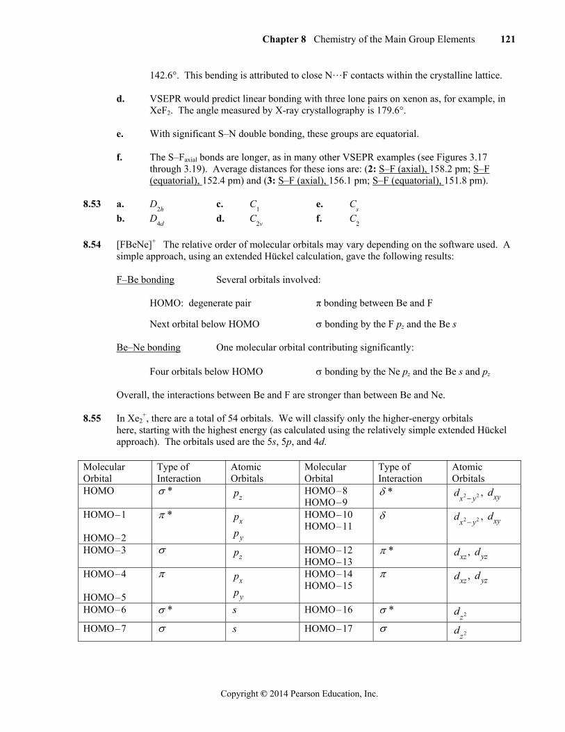
Overall, the interactions between Be and F are stronger than between Be and Ne. 8.55 In Xe2
+, there are a total of 54 orbitals. We will classify only the higher-energy orbitals here, starting with the highest energy (as calculated using the relatively simple extended Hückel
approach). The orbitals used are the 5s, 5p, and 4d. Molecular Orbital
Type of Interaction
Atomic Orbitals
Molecular Orbital
Type of Interaction
Atomic Orbitals
HOMO * pz HOMO – 8 HOMO – 9
* dx2 y2 , dxy
HOMO – 1 HOMO – 2
* px
py
HOMO – 10 HOMO – 11
dx2 y2 , dxy
HOMO – 3 pz HOMO – 12 HOMO – 13
* dxz , dyz
HOMO – 4 HOMO – 5
px
py
HOMO – 14 HOMO – 15
dxz , dyz
HOMO – 6 * s HOMO – 16 * dz2
HOMO – 7 s HOMO – 17 dz2
122 Chapter 8 Chemistry of the Main Group Elements
Copyright © 2014 Pearson Education, Inc.
If this were neutral Xe2, there would be no bond, because every occupied bonding orbital would be offset by an occupied antibonding orbital. In Xe2
+, one electron has been removed, so
the bond order is 1
2, making for a long bond. The large atomic radius of Xe further predisposes
Xe2+ to having a long bond. It is noteworthy that bonding is exceedingly weak in this species
since the overlap leading to formation of the and * orbitals is very small.
8.56 The reference by Steudel and Wong provides illustrations for the four highest occupied molecular orbitals. In addition to the interesting symmetry of these orbitals, the way in which the * orbitals of O2 are imbedded in the molecular orbitals of O8 should be noted.