chapter 8 muon collider ring - brookhaven national … · chapter 8 muon collider ring contents ......
TRANSCRIPT

Chapter 8
MUON COLLIDER RING
Contents
8.1 Introduction . . . . . . . . . . . . . . . . . . . . . . . . . . . . . . 326
8.2 Lattice . . . . . . . . . . . . . . . . . . . . . . . . . . . . . . . . . 327
8.2.1 Overview . . . . . . . . . . . . . . . . . . . . . . . . . . . . . . . . 328
8.2.2 Components of the Lattice . . . . . . . . . . . . . . . . . . . . . . 330
8.2.3 Performance . . . . . . . . . . . . . . . . . . . . . . . . . . . . . . 334
8.2.4 Control of the Momentum Compaction . . . . . . . . . . . . . . . 336
8.2.5 Collider lattice comparisons . . . . . . . . . . . . . . . . . . . . . . 338
8.2.6 Summary . . . . . . . . . . . . . . . . . . . . . . . . . . . . . . . . 339
8.3 Superconducting Magnets . . . . . . . . . . . . . . . . . . . . . . 340
8.3.1 Energy Deposition Due to Muon Decay . . . . . . . . . . . . . . . 341
8.3.2 Collider Ring Dipoles . . . . . . . . . . . . . . . . . . . . . . . . . 342
8.3.3 Collider Ring Quadrupoles and Sextupoles . . . . . . . . . . . . . 343
8.3.4 Reduction of Heat Load in SC magnets . . . . . . . . . . . . . . . 344
8.4 Radio-Frequency System for the Collider Ring . . . . . . . . . . 347
8.5 Ring Vacuum Chamber . . . . . . . . . . . . . . . . . . . . . . . . 350
8.5.1 Particle Fluxes . . . . . . . . . . . . . . . . . . . . . . . . . . . . . 350
8.5.2 Beam Gas Scattering and Beam Tube Gas Density Requirement . 353
8.5.3 Sources of Beam Tube Gas and Estimate of Beam Tube Gas Density354
8.5.4 Beam Tube Resistivity and Image Current Losses . . . . . . . . . . 355
8.6 Classical Beam-Beam Interaction . . . . . . . . . . . . . . . . . . 355
325

326 CHAPTER 8. MUON COLLIDER RING
8.6.1 Introduction. . . . . . . . . . . . . . . . . . . . . . . . . . . . . . . 356
8.6.2 Physics of the Incoherent Simulation. . . . . . . . . . . . . . . . . 357
8.6.3 Beam-beam Simulation. . . . . . . . . . . . . . . . . . . . . . . . . 358
8.6.4 Other Classical Beam-Beam Issues. . . . . . . . . . . . . . . . . . . 363
8.6.5 Summary . . . . . . . . . . . . . . . . . . . . . . . . . . . . . . . . 366
8.7 QED Effects at the Interaction Region . . . . . . . . . . . . . . 367
8.8 Single Bunch Collective Effects . . . . . . . . . . . . . . . . . . . 370
8.1 Introduction
The collider ring of the Muon Complex allows for (about) 1000 collisions per bunch, rather
than the single collision that is possible in a linear collider geometry. If the transverse beam
size at the collision point in a muon collider were the same as that in an electron-positron
linear collider, there would be a full increase in luminosity of order 1000. This is not the case.
The muon bunch is cooled as much as possible, but still has an emittance that is significantly
larger than the extremely low emittances required in an electron-positron linear collider. The
luminosity scales as L = fN2/((εxβ∗x)(εyβ∗y))
1/2, where εx(y) is the beam emittance in the
x(y) phase plane, β∗x(y) the corresponding beta-function at the interaction point (which is
limited, by the hour-glass effect, to be no less than the bunch length), and f the collision
frequency.
While the NLC electron-positron linear collider and the muon collider are quite different,
in particular this muon collider feasibility study is for a 4 TeV (center of mass) machine and
the NLC energy range is .5-1.5 TeV, it is instructive to compare the parameters that are
required for achieving the design luminosity. For typical NLC parameters: f = 18, 000 =
100×180 (bunches per pulse × pulses per second), N = 1010, εnx = 5×10⁻⁶m, β∗x = 10−2m,
εny = 5× 10⁻⁸m, β∗y = 10−4m for a luminosity of 7× 1033cm−2s−1 at 250 GeV × 250 GeV.
In contrast, the muon collider has f = 30, 000Hz = 2× 1000 × 15 (bunch pairs/pulse ×
collisions/bunch-pair × pulses/second), N = 2×10¹², a round beam with εn = 5×10⁻⁵mrad,
β∗ = 3×10⁻³ m, for a luminosity of 1035cm−2s−1 at 2 TeV × 2 TeV. Thus, the muon collider
achieves its luminosity primarily with an increased number of particles (and from an increased
number of collisions per bunch-pair). The muon collider has a much larger emittance and
beam size at the IP (σxσy|NLC ≈ 10−15m2, while σxσy|muon ≈ 10−12m2). The large emittance
may relax some tolerances on component alignment compared to electron-positron linear
colliders, but these bunch parameters, coupled with the need to store ∼ 1000 turns, present
many difficulties.

8.2. LATTICE 327
The ring design is challenging, with its high current, low beta, and isochronicity re-
quirements. The low beta and high current are required to obtain the luminosity, and the
isochronicity is required to maintain the short bunch length without excessive rf. Luminos-
ity cannot be further increased by reducing the muon bunch length, for the bunch length is
determined by longitudinal cooling, which is, already, as much as can be done. For the very
high charge one must be concerned with collective instabilities and wakefields.
The ring brings many technical complications to the project (as well as cost, not ad-
dressed herein), but we we have an ideas on how each can be handled, and advocate further
investigation of a collider ring that achieves the very high luminosity requisite for operation
at high energy.
This chapter examines the design and analysis of various systems envisioned for the muon
collider main ring. This work includes magnet designs, lattice design, vacuum requirements,
analysis of collective instabilities, and beam-beam interaction. First lattice studies are pre-
sented (Section 8.2), and then the superconducting magnets, both dipoles and quadrupoles
(Section 8.3). In Section 8.4 we consider the ring rf system. Section 8.5 is devoted to the
vacuum chamber which require special care as it must absorb the energy of decay electrons
and their synchrotron radiation. The classical beam-beam interaction, incoherent and co-
herent, are covered in the next section (Section 8.6). Incoherent pair production is covered
in Sec. 8.7. Finally, in Section 8.8, collective effects are discussed. The major parameters of
the muon collider are presented in Table 8.1.
8.2 Lattice
The lattice for a 2-TeV on 2-TeV muon collider must satisfy three major design constraints.
The first and most difficult of these is provision of an Interaction Region (IR) with an ex-
tremely low β∗ (∼ 3 mm) consistent with an acceptable dynamic aperture. Second, the ring
must exhibit a high degree of isochronicity in order to preserve short 3 mm long bunches
with a modest rf system. Lastly, there must be small corrected chromaticity, so that the
momentum-dependent tune spread of the beam fits between resonances. Technically, consid-
erable shielding must be incorporated into the design to protect the superconducting magnets
from the high muon-decay backgrounds. The following sections describe a preliminary lat-
tice, Ref. [1], which is intended to meet the above requirements.
328 CHAPTER 8. MUON COLLIDER RING
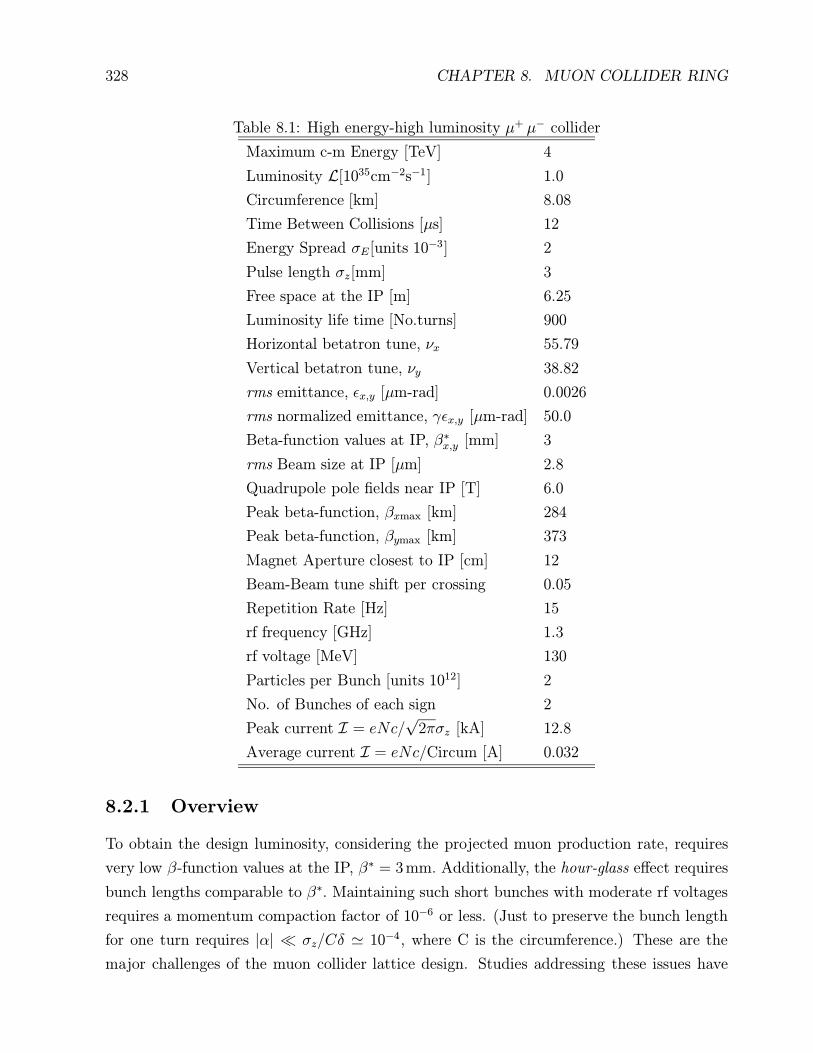
Table 8.1: High energy-high luminosity µ+ µ− collider
Maximum c-m Energy [TeV] 4
Luminosity L[1035cm−2s−1] 1.0
Circumference [km] 8.08
Time Between Collisions [µs] 12
Energy Spread σE[units 10−3] 2
Pulse length σz[mm] 3
Free space at the IP [m] 6.25
Luminosity life time [No.turns] 900
Horizontal betatron tune, νx 55.79
Vertical betatron tune, νy 38.82
rms emittance, εx,y [µm-rad] 0.0026
rms normalized emittance, γεx,y [µm-rad] 50.0
Beta-function values at IP, β∗x,y [mm] 3
rms Beam size at IP [µm] 2.8
Quadrupole pole fields near IP [T] 6.0
Peak beta-function, βxmax [km] 284
Peak beta-function, βymax [km] 373
Magnet Aperture closest to IP [cm] 12
Beam-Beam tune shift per crossing 0.05
Repetition Rate [Hz] 15
rf frequency [GHz] 1.3
rf voltage [MeV] 130
Particles per Bunch [units 1012] 2
No. of Bunches of each sign 2
Peak current I = eNc/√
2πσz [kA] 12.8
Average current I = eNc/Circum [A] 0.032
8.2.1 Overview
To obtain the design luminosity, considering the projected muon production rate, requires
very low β-function values at the IP, β∗ = 3 mm. Additionally, the hour-glass effect requires
bunch lengths comparable to β∗. Maintaining such short bunches with moderate rf voltages
requires a momentum compaction factor of 10−6 or less. (Just to preserve the bunch length
for one turn requires |α| σz/Cδ ' 10−4, where C is the circumference.) These are the
major challenges of the muon collider lattice design. Studies addressing these issues have

8.2. LATTICE 329
Figure 8.1: The complete collider ring layout.
been recently published [2].
The very small β∗ requirement is particularly difficult to achieve because substantial
space must be reserved for the detector about the IP and also because the superconducting
magnets must be shielded from the decay products of the muon beam. In the initial design,
superconducting quadrupoles nearest the IP had to accommodate a 6 cm thick tungsten liner
in order to dissipate heat generated by the beam. Recent work has been successful in reducing
the required shielding to 2 cm using combinations of sweep dipoles and collimators. With the
thicker liner, quadrupole gradients were reduced by about a factor of 4 near the IP. However,
with the thinner liner, the strength reduction will be factor of 2, since the beam size and liner
thickness will be comparable. Additionally, a magnet-free length of ±6.5 m must be reserved
about the IP to provide the ±150 mr acceptance angle needed for the detector. As a result,
peak beta-function values as high as several hundred kilometers cannot be avoided; these
high values produce extremely large chromaticities (several thousand before correction).
One preliminary design of an entire collider ring has been developed using the experimen-
tal insertion and arc modules described in Ref.[2]-[4] plus a utility insertion. A schematic
layout of this ring design is shown in Fig. 8.1. A second collider ring design, has been de-
veloped by K. Oide[4]. This design incorporates a more sophisticated nonlinear correction
scheme in the IR. Unfortunately, because of time constraints, it was impossible to include an
equal discussion of the two designs here. Therefore, we will proceed with a detailed presen-
tation of the first design, to be followed by a section comparing the two designs, and, finally,
a discussion of recent progress.

330 CHAPTER 8. MUON COLLIDER RING
8.2.2 Components of the Lattice
The ring has an oval shape, with reflection symmetry about two perpendicular axes, see
Fig. 8.1. The lattice has two nearly circular 152 arcs joined by two insertions, each contain-
ing two 14 bending sections. These are called the experimental and utility insertions.
The two arcs are identical; each contains 22 periods and one dispersion suppressor at
each end. The insertions are geometrically identical; each is symmetric about its center.
Each half insertion has three parts: two straight sections separated by a bending section.
The bending sections are identical in the experimental and utility insertions, except for the
sextupole strengths. In contrast, the straight parts have different quadrupole lengths and
gradients in the two insertions. Thus, as a focusing structure the ring has one superperiod
with reflection symmetry about the line joining the centers of the two insertions.
Arc module In order to have very short 3 mm bunches in the 2 TeV muon collider, the
storage ring must be quasi-isochronous, which requires that the momentum compaction α
be very close to zero[9], where α is defined in terms of offsets of the momentum p and
equilibrium orbit circumference C by
α(p) =p
C
dC
dp. (8.1)
The lattice must be designed so that over the momentum range, the momentum compaction
remains small.
The particle motion in longitudinal phase space depends on its arrival time at the RF
cavities, which varies as a function of circumference and velocity v. To first order the time
difference with respect to the reference particle is:
∆T
T0
= η∆p
p0
= (α0 −1
γ2)∆p
p0
, (8.2)
where T0 and α0 are the revolution period and momentum compaction of the reference parti-
cle; ∆T and ∆p are the time and momentum deviations, respectively, of the off-momentum
particle relative to the synchronous particle with momentum p0; η is the phase slip factor;
γ is the Lorentz relativistic factor, and α0 = α(p0). The transition energy γt is defined by
α = 1/γ2t .
In an isochronous ring η = 0, so to first order the arrival time is independent of the
momentum; i.e., γt = γ. For 2 TeV muons γ ≈ 2 × 10⁴, so α ≈ 2.5 × 10⁻⁹. In a regular
FODO lattice, α is much larger. To bring the first order value of α to zero requires that the
〈D/ρ〉 through all of the dipoles be equal to zero, where D is the dispersion and ρ the radius
of curvature.

8.2. LATTICE 331
Figure 8.2: Betatron (βx solid-line; βy dash-line) and dispersion (dot-line) functions of an
arc-module.
In a FODO lattice α is positive. This muon collider ring design has bending regions in the
insertions with a FODO structure whose contributions to α are positive, so the contributions
of the arcs must be negative with nearly the same magnitude as those of the insertions. For
the present design, the value needed for each arc is αarc = −1.15 × 10⁻⁴.
This value of αarc can be obtained by building an arc whose periods are FMC modules.
An FMC module[4] is a structure composed of two FODO cells separated by a matching
insertion which transforms (βx, αx, βy, αy, D,D′) to (βx,−αx, βy,−αy, D,−D′.)
The contribution to α of the module can be adjusted by choosing the appropriate value of
D with D′ = 0 at the end of the module. For the module design used here (see Fig.8.2), the
matching insertion contains two quadrupole doublets and two dipoles. The two quadrupole
gradients and drift lengths are adjusted to bring αx, αy and D′ to zero at the center of the
module. The number of modules and the bending angles of the dipoles are chosen to give
the entire arc the bending angle of 152 needed to close the ring.
The arc modules also contain sextupoles; there are two families adjusted to bring the
chromaticities of the arc to zero.
Dispersion suppressor A dispersion suppressor module is located at each end of the arc.
The purpose of these modules is to bring the dispersion and its slope to zero values in the
adjacent insertions.
The suppressor on the downstream end just before an insertion is shown in Fig.8.3; the
upstream suppressor is obtained by reflection. This suppressor module is identical to a

332 CHAPTER 8. MUON COLLIDER RING
Figure 8.3: Betatron (βx solid-line; βy dash-line) and dispersion (dot-line) functions of a
dispersion suppressor module.
regular module except that the first four dipoles have been replaced by two dipoles with
normal length and different field values. The missing dipoles have been replaced by drift
spaces so that the quadrupoles and sextupoles are not changed.
Experimental insertion The design of an insertion with an extremely low-beta interac-
tion region for a muon collider[5] presents a challenge similar to that encountered for the
Next Linear Collider (NLC)[6]. The design used here for each half of the symmetric low-beta
insertion follows the prescription proposed by Brown[7]; it consists of two telescopes with a
chromatic correction section between. Fig.8.4 shows the left half of the insertion, starting at
the end of the arc dispersion suppressor and ending at the IP.
The first telescope, called the Matching Telescope (MT), on the left of the figure, brings
the beta functions from the arc to a focus of about 3 cm. To the right of the MT lies the
Chromatic Correction Section (CCS), which contains two pairs of non-interleaved sextupoles.
One pair, situated at positions of maximum βx and large dispersion D, corrects horizontal
chromaticity; the other pair, at maximum βy positions, corrects vertical chromaticity. The
horizontal-correcting pair is farthest from the IP, and the vertical-correcting pair is closest.
The sextupoles of each pair are separated by betatron-phase intervals of φ = π, and they
are located at positions where the phase interval from the IP is an odd multiple of π/2. To
the right of the CCS, the Final Focus Telescope (FFT) transports the beta functions from a
focus of a few centimeters to a 3 mm focus at the IP.
The low beta-function values at the IP are obtained with four strong quadrupoles in

8.2. LATTICE 333
Figure 8.4: Experimental insert (half) with extremely small beta function at the IP.
the FFT with high beta values; these generate large chromaticities, which are corrected
locally with the two sextupole pairs in the CCS. This sextupole arrangement cancels the
second-order geometric aberrations of the sextupoles, which reduces the second order tune
shift by several orders of magnitude. The momentum bandwidth of the system is limited by
third-order aberrations and residual second-order amplitude-dependent tune shifts. These
aberrations arise from: a) small phase errors between the sextupoles and the final quadruplet;
b) finite length of the sextupoles.
The residual chromaticities could be reduced with additional sextupoles at locations with
nonzero dispersion, as suggested by Brinkmann[8]. Finally, a system of octupoles could be
designed to correct third-order aberrations. Overall, it is believed possible to construct a
system with a bandwidth of ≈ 1 %.
The most complex part of the insertion is the CCS. A somewhat oversimplified description
follows. The CCS consists of eight FODO cells, each with π/2 phase advances. The first four
cells from the left begin at the center of a QF quadrupole and contain the two horizontal Sx
sextupoles, which are next to QFs; the next four cells begin at the center of a QD quadrupole
and contain the vertical Sy sextupoles, which are next to QDs. The low-beta focus at the
beginning of the CCS repeats itself every two cells and produces the high beta values needed
in the sextupoles. The dipoles are placed in a way to cancel the dispersion and its slope at
both ends of the CCS and to produce dispersion maxima in the sextupoles.
The strengths of the sextupoles Sx and Sy are adjusted to produce zero first-order chro-
maticity values for the insertion, while trim quadrupoles are used to minimize the second
order chromaticity (∂2Q/∂δ2). The complete insertion has very small residual chromaticity,

334 CHAPTER 8. MUON COLLIDER RING
and is nearly transparent when attached to the arc lattice.
The total length of the half-insertion is 507 m. It contains 44 quadrupoles, 14 dipoles
and 4 sextupoles.
Utility insertion The utility insertion closely resembles the experimental insertion, except
that the low-beta foci are relaxed in order to lower the beta-function maxima by a factor of
about 1000.
Figure 8.5: Utility insertion (half)
The CCS section for the utility insertion is the same as the one in the experimental insertion,
except that the sextupoles are adjusted to cancel the chromaticities of the utility insertion
(which are much smaller than those of the experimental insertion). Further changes will
probably be needed to accommodate systems for injection, RF, and scraping.
8.2.3 Performance
The variations of the fractional part of the tunes Qx,y as functions of δ are shown in Fig.8.6.
Qy is essentially flat over a bandwidth of ±0.4%; Qx has obvious non-linear components,
although the variation of tune, peak to peak is less than 0.04 within a bandwidth of −0.15 %
to 0.3 %. Likewise, the β∗ variation (Fig.8.7) is negligible within a bandwidth of ±0.3 %. The
remaining figures show the chromaticity (Fig.8.8), the momentum compaction α (Fig.8.9)
and the amplitude dependent tunes dQ/dε (Fig. 8.10), versus δ. ¿From the results shown in

8.2. LATTICE 335
Figure 8.6: Fractional tunes Qx,y vs ∆pp
Figure 8.7: Beta function β∗ vs ∆pp
the above figures, it appears that the momentum aperture of the CD has a range δ = ∆p/p
of 0.007.
The variation of the momentum compaction factor α versus δ, shown in Figure 8.9, is
too large to preserve short bunches with a moderate rf voltage. Methods for coping with
this problem are discussed in the following section.
Tracking runs [11] using TEAPOT indicate that the dynamic aperture (about one sigma)
is too small by roughly a factor of four. The lattice is presently being tuned to increase its
dynamic aperture and, along with recent improvements, the aperture has been increased to

336 CHAPTER 8. MUON COLLIDER RING
Figure 8.8: Chromaticity vs ∆pp
Figure 8.9: Momentum compaction α vs ∆pp
about five sigma without changing its basic structure. The improvements and adjustments
to the collider lattice are outlined in Section 8.2.5.
8.2.4 Control of the Momentum Compaction
The collider ring lattice has been adjusted to be approximately isochronous for the reference
particle. That is, the lattice has been designed so that the momentum-compaction factor,

8.2. LATTICE 337
Figure 8.10: Amplitude dependent tune shift dQdε
vs ∆pp
α(p), defined by
α(p) =p
C
dC
dp. (8.3)
is approximately zero. In practice, in order to maintain a 3 mm bunch and a modest rf, α(p0)
must be about 10−6.
However, over the desired momentum aperture, α(p) varies, as shown in Figure 8.8, so
that over the momentum range of ±.004, α(p) exceeds 10−5. If we expand α(p) in powers of
δ = p/p0 − 1:
α(p) = α1 + α2δ + α3δ2 +O(δ3) (8.4)
we see from Figure 8.9 that α1 = 0, and α2 = 0.006. This value of α2 leads to an unacceptable
longitudinal head-tail instability. Since α2 has a contribution from each sextupole of −2SD3,
where S is the strength and D is the dispersion in the sextupole, it is possible to correct α2
with one or more sextupole families.
Initially, horizontal and vertical chromaticities, but not the α2, of the arcs, experimen-
tal insertion and utility insertion were canceled using three independent pairs of sextupole
families. Alternatively, the chromaticities of the ring, most of which arise from the experi-
mental insertion, can be canceled by using only the insertion sextupoles. This frees the arc
sextupoles to control α2. Specifically, by inserting a horizontal sextupole next to each of the
central F quadrupoles in the arc modules, the α2 term can be eliminated.
It is possible to control both the linear α2 and the quadratic α3 coefficients using two
sextupoles pairs in each module, one pair next to the two center QFs and the other pair
next to the QF at the module ends–see Figure 8.2. By choosing appropriate strengths for

338 CHAPTER 8. MUON COLLIDER RING
the different sextupole families, one can make α2 ' α3 ' 0, which reduces the variation of
α over a range in δ of ±.004 to only about 10−7 (for the arcs). Unfortunately, this method
halved the total stable momentum range of the ring.
Another way to control α2 without generating a contribution to α3 is to pair sextupoles
separated by phase intervals of π in the arcs. Thus we conclude that control over both α2
and α3 can be achieved to a precision of 10−7; however, this degree of correction may not be
necessary (especially for α3).
In summary, the isochronicity of the ring can be controlled precisely. The momentum-
compaction coefficients chosen for the ring will be based on rf bucket and collective instability
calculations.
8.2.5 Collider lattice comparisons
As mentioned previously, a different design for the muon collider has been developed by K.
Oide[2]. For discussion purposes, the detailed design presented in this document will be
referred to as the CD (collaboration design) and Oide’s design as the OD. Since tracking
results show the OD to have larger dynamic aperture than the CD, the following discussion
of the salient differences between the two lattices may be useful.
For the arcs, the CD uses FMC modules, while the OD adopted the KEK B factory
modules. Since the dynamic aperture problems arise from the IR, not from the arcs, this
difference is probably unimportant.
Both the CD and the OD are similar to linear collider IRs, but there are important
differences between these two designs. In the CD the maximum horizontal and vertical beta-
function values, and consequently the chromaticities, are equalized. On the other hand, in
the OD, the horizontal βxmax is less than βymax by more than an order of magnitude. As
can been seen from the table, the OD ring has a substantially larger vertical high-beta value
(900 vs. 350 km) than the CD, and its apertures are correspondingly larger. The vertical
chromaticity comparison is less dramatic, since the increased βymax is offset by the shortened
length of the high-beta quadrupoles.
The unequal βmax values in the low-beta quadrupoles of the OD compensates for the
chromatic correction scheme which favors the vertical plane, due to the fact that the vertical
sextupoles are closer to the IP than the horizontal ones. (Increased nonlinearities in the x
plane are caused by the intervening y-plane sextupoles.) Thus, for a 2-TeV muon collider,
it appears that an asymmetry in chromaticity may be important for chromatic correction.
The strength of the chromatic correction sextupoles is another contributing factor to
nonlinearites. In the OD, increased dispersion and much higher β functions allowed the

8.2. LATTICE 339
correction sextupole strengths to be reduced by almost an order of magnitude compared
with those of the CD.
The last important feature of the OD to be mentioned here is the addition of octupole
and decapole components in the IR quadrupole fields; this addition appeared to increase the
dynamic aperture dramatically.
Modifications to the present CD currently under investigation include use of unequal
maximum βx,y values, optimization of the chromatic correction section, use of higher mul-
tipole corrections, and addition of permanent-magnet quadrupoles between the IP and the
first superconducting quadrupole.
8.2.6 Summary
Studies have been underway to improve the experimental insertion. The approach of placing
permanent magnets within 2 m of the IP to reduce βmax and chromaticity has been discarded.
Exposure to the high radiation environment in a muon collider ring raised concern over the
magnetic field lifetime of a permanent magnet. Instead, a ”Bitter” quadrupole is being
considered as an alternative magnet to place near the IP. In a preliminary design by B.
Weggel during the Snowmass conference, a small ”Bitter” quadrupole was introduced with a
pole-tip field of just under 4 T. Shielding modifications included placing tungsten collimators
between the superconducting IR quadrupoles to shadow and thus protect them from the
high backgrounds. To be effective, the collimators had to be 15 cm long with a 4-sigma
aperture (the quadrupoles have a 5-sigma aperture). Additionally, sweep dipoles were placed
about a meter upstream of the final-focus quadrupoles to eliminate the muon-decay products
generated in the preceding long drift. In the previous IR design, most of the decay products
struck the IR quadrupoles, creating the unacceptable heat loads.
The combined effect of adding dipoles and collimators to the IR allowed the protective
tungsten liner of the superconducting elements to be reduced from 6 cm to 2 cm. This
allowed the effective gradient of the final-focus quadrupoles to be increased. When the
Bitter quadrupole was also included and placed 4 m away from the IP, peak β functions
decreased by almost a factor of two, and chromaticities by a factor of 3 in the horizontal
plane and 2 in the vertical. Higher order aberrations were reduced by about two orders of
magnitude.
Initially, the dynamic aperture did not increase as a consequence of the IR improvements.
The reason for this proved to be the CCS. Optimization work on the CCS proved to be as
important as the improvements made to the IR. To maximize momentum aperture, the peak
β functions in the chromatic correction sextupoles were deliberately large, which had the

340 CHAPTER 8. MUON COLLIDER RING
intended effect of reducing their strength and therefore their contribution to higher-order
aberrations. However, the large beta functions in the sextupoles increased significantly
their contribution to amplitude-dependent tuneshifts. A better way to decrease sextupole
strength (and length) is to increase the dispersion function at their locations. Increasing the
dispersion and reducing the peak β functions at the sextupoles was the approach used to
minimize their higher-order contributions to the amplitude-dependent tuneshifts (without
increasing aberrations significantly). When peak β functions in the CCS were reduced from
100 km to 50 km, tracking showed the on-momentum aperture to be 5 sigma. The full
momentum acceptance was .3%. Results were found to be strongly tune-dependent and a
phase trombone was introduced into the collider ring to adjust tunes independently and
without disturbing the lattice. Presently a 10−km version of the CCS with same final focus
structure is being tested.
After the FT and CCS optimization is complete using only sextupoles, the addition of
octupoles and perhaps decapoles will be studied to further reduce the amplitude-dependent
and aberration terms. Also, in future, it is hoped that the ”Bitter” quadrupole, which has a
high power consumption, can be removed if high Tc superconductor research indicates that
we can employ stronger quadrupole gradients in the final focus.
8.3 Superconducting Magnets
The number of collisions during a storage time is inversely proportional to the ring diameter,
since the muon decay time constant is fixed by the muon energy. The dipoles in the ring
should therefore have a very high field. A reasonable value is 8.5T, supplied by superconduct-
ing magnets. As in other rings, the superconductor must be shielded from heat generated
by the beam. In the muon collider there are several heat sources: 1) Muon synchrotron
radiation, 2) Muon decay (electrons, positron and their synchrotron radiation; neutrinos
pass through the walls and do not deposit energy in the accelerator components), 3) Muons
that escape from the bunch and hit the vacuum chamber. Estimates show that muon syn-
chrotron radiation is not significant at 2 TeV and that muons that escape from the bunch
can be held to a low level. Thus the main contribution to the heating comes from the decay
electrons and positrons hitting the inner wall of the vacuum chamber and the synchrotron
radiation they emit hitting the outer wall. Secondary radiation from these impacts in turn
deposits energy elsewhere in the aperture. The magnet requirements for a muon collider
are thus strongly influenced by the decay of the muons. The muons decay into electrons
and positrons with around 35% of the muon energy. In the main ring, this amounts to a
significant power deposition in the walls. Either a thick absorber will need to surround the

8.3. SUPERCONDUCTING MAGNETS 341
vacuum chamber, increasing the bore of the magnets, or a magnet design that moves the
superconducting coils off the midplane (so that absorbing material in the midplane of the
ring can be some distance from the coil) needs to be developed.
This section describes design options for dipoles and quadrupoles for the collider ring. It
does not include any discussion about superconducting magnets needed in other subsystems
of the muon collider nor those that are part of the detector system around the collision point.
8.3.1 Energy Deposition Due to Muon Decay
The collider will be a single separated function ring of superconducting magnets that guides
both the negative and the positive muons. The number of muons that decay in a given
length LT can be estimated using the expression
Nd =NµLTE0
τ0ET c(8.5)
where Nµ is the number of muons transported through a structure per second, Nd is the
number of muons that decay in the structure per second, LT is the length of the structure,
ET is the muon energy, E0 is the muon rest energy, c is the speed of light, and τ0 is the
muon decay time constant at rest (τ0 = 2.197 × 10⁻⁶ s). Equation 8.5 is applicable when
the transit time for the muon through length L is less than the decay time constant of the
muon at energy ET . The power deposited into the magnet structure from muon decay can
be estimated using the expression
P ' 0.35NdEave (8.6)
where Nd is the number of muons that decay per second (See Equation 8.5), and Eave is the
average energy of the muon in the structure. The factor 0.35 in Equation 8.6 is the portion of
the muon energy that ends up in the decay electrons or positrons. The remainder of the muon
energy is transported out of the ring by the decay neutrinos. Table 8.2 presents calculations
for muon decay in each of the accelerator components and the collider ring. Included in
the Table 8.2 is the number of turns through the component and the total transit length
LT through the structure. Table 8.2 gives an estimate of the decayed muon power that is
transferred to electrons and positrons. This is the portion of the decayed muon power that
can end up in the superconducting magnet system. The beam flux of muons that enters the
accelerator section is assumed to be 3× 10¹² muons per bunch.
The size of the region where the decay electrons, positrons and synchrotron radiation
strike the wall of the vacuum chamber is determined primarily by the kinematics of the
decay process. For a 3σ vertical beam size of 4 mm, this region is only about 5 or 6

342 CHAPTER 8. MUON COLLIDER RING
Table 8.2: Muon decay parameters for various parts of a muon collider
Component Peak
Energy
(GeV)
Number
of
Turns
LT(km) Total
Muon
Decay
Rate
1013s−1
Heating
Power
(kW)
Peak
Heat per
unit L
(Wm−1)
Linac 1.0 -NA- 0.12 1.9 0.6 -NA-
First Ring 9.6 9 2.17 1.2 3.6 1.64
Second Ring 79 12 11.3 0.8 19.7 1.75
Third Ring 250 18 29.2 0.4 36.8 1.26
Fourth Ring 2000 18 227 0.6 378 1.66
Collider Ring 2000 1000 7.9 13.1 14600 1840
mm high even at muon energies as low as 20 GeV. As stated earlier, however, secondary
interactions cause considerable energy deposition to occur throughout the aperture, so all of
the aperture must be considered in the design of any energy-absorbing system. Calculations
of energy deposition in the magnet structure are given in section 8.3.4.
8.3.2 Collider Ring Dipoles
The design of the dipoles and quadrupoles is dependent on the percentage of the muon
decay product energy that can be removed from within the 4 K mass of the dipole before
degradation of magnet performance. Several design approaches can be considered for the
superconducting dipole magnets in the collider ring. One approach is to use a conventional
cosine theta type of dipole provided the heavy (tungsten) radiation shield is thick enough to
reduce the energy into the superconducting coils by about three orders of magnitude. The
collider dipole warm bore is about 20 mm. The thickness of tungsten needed to reduce the
heating from muon decay by three orders of magnitude is about 65 mm. Thus, the cold
bore of the superconducting dipole coils must be 160 mm. The heavy radiation shield could
be cooled with a fluid at room temperature. A collider ring dipole with a tungsten liner is
illustrated in Fig. 8.11. The energy from the decay products that escapes this liner is well
diffused in the coils (see section 8.3.4). Another approach to building collider ring dipole
magnets is to have the coils completely separated on the mid plane. The iron return yoke
would probably be cold because of the heavy supports needed between the yoke and the coils
to restrain the attractive forces between coils. The coils must be separated so that less than
0.1% of the energy from the muon decay products ends up in the superconducting coils or

8.3. SUPERCONDUCTING MAGNETS 343
Cold Iron
100 mm
Water Cooled 300 K Tungsten Shield
SpacerSuperconducting Coil
20 mm Dia. Beam Pipe
Figure 8.11: A cold iron 8.5 T cosine theta dipole with a 65 mm thick tungsten liner at 300
K
its surrounding support structure that is at 4 K. The rest of the muon decay product energy
ends up in the separately-cooled radiation shield. Figure 8.12 shows cold iron dipoles with
separation between the coils to allow for a warm vacuum chamber. The dipoles shown in
Fig. 8.12 have reasonably good field quality.
Calculations by I. Stumer (private communication) suggest that almost all of the muon
decay energy could be captured in absorbers placed at the ends of the magnets. The absorbers
would have narrow apertures to capture as much of the radiation as possible yet allow passage
of the beam; these narrow apertures may present beam impedance problems. Further work
is necessary to confirm the viability of this promising approach.
8.3.3 Collider Ring Quadrupoles and Sextupoles
Several designs can be considered for the collider ring quadrupoles. 1) A design with a thick
tungsten liner, similar to the dipole of Fig. 8.11, can be made. With the same 160 mm cold
bore aperture, a gradient of 100 T/m could be achieved. 2) A figure-of-eight conventional
quadrupole with a pole radius of 12 mm can be used. Conventional quadrupoles of this size
can achieve a gradient of 100 to 120 T/m. Most of the muon decay energy can be absorbed by
a cooled absorber outside the quadrupole. 3) A quadrupole can be designed that has its coils
off the mid plane, Fig. 8.13. This quadrupole design is similar to the dipole design shown
in Fig. 8.12. Depending on the field allowed in the superconductor, quadrupole gradients of
140 to 180 T/m can be achieved.

344 CHAPTER 8. MUON COLLIDER RING
Cold Iron
Superconducting Coil
Muon Beam
b) Cold Iron H Dipole Magnet
Room TemperatureMuon Decay Product
Energy Absorber
300 K Water Channel
100mm
Cold Iron
Superconducting Coil
Room TemperatureMuon Decay Product
Energy Absorber
Muon Beam
a) Cold Iron C Dipole Magnet
300 K Water Channel
Figure 8.12: Two versions of an 8.5 T cold iron split dipole that would have less than 0.1%
of the muon decay power deposited within the superconducting coils
The tuning sextupoles for the collider ring can be conventional. If these sextupoles have
the pole at a radius of 12 mm, gradients as high as 3000T/m2 may be achieved. There
appear to be no superconducting sextupole designs able to absorb the muon decay products
that can achieve this gradient.
8.3.4 Reduction of Heat Load in SC magnets
Due to muon decays, about 2 kW of power are deposited every meter along the collider
ring.This results in a heat load that significantly exceeds levels that can be tolerated by
existing SC magnets. The energy-deposition distributions in the storage ring components

8.3. SUPERCONDUCTING MAGNETS 345
Figure 8.13: A quadrupole design that avoids superconductor on the midplane so that muon
decay particles can escape. The drawing shows one pole of the design
from muon decay have been calculated for a 2 TeV muon beam with the mars code [12].
Even with a longitudinally uniform source, there is an increased background at the high-
βpeak locations near the IR. Fig. 8.14 shows the azimuthal distribution of power deposited
in the first cable shell of the arc SC magnets with tungsten liners of different thicknesses.
There is a significant azimuthal dependence of power density due to the effect of the strong
magnetic field. The lateral gradient of energy deposited in the SC coil is very strong both
with and without a liner. The peak power density exceeds the expected quench limits for
the magnet of the assumed type by more than an order of magnitude. A 4 cm tungsten liner
provides a considerable reduction of the maximum power deposition density from the quench
stability standpoint (see Fig. 8.15). Another concern is the power dissipation in the cold
magnet components. As mentioned above, up to 1 kW of power per each beam would be
deposited in every meter of the lattice, which is about 1000 times above a possible limit for
such extended systems as a collider ring. Fig. 8.16 shows power dissipation in tungsten liner,
liquid helium, SC coils, yoke and cryostat components as a function of the liner thickness per
one meter of the arc lattice per one beam. One sees that 6 cm liner is required in the arcs
in a cosine theta approach. The studies show that in the interaction region two quadrupoles
nearest to the interaction point also need at least 6 cm of tungsten shield in front of the SC

346 CHAPTER 8. MUON COLLIDER RING
0 90 180 270 360Azimuthal Angle (deg)
10-3
10-2
10-1
100
101
Po
we
r D
en
sity
(m
W/g
)
1 cm2 cm3 cm5 cm
Tungsten Liner:
Figure 8.14: Azimuthal distribution of power density in the first SC cable shell in the collider
arc for different tungsten liners inside the aperture for 2 TeV muon beam decays

8.4. RADIO-FREQUENCY SYSTEM FOR THE COLLIDER RING 347
1 2 3 4 5 6Liner Thickness (cm)
10-2
10-1
100
101
Po
we
r D
en
sity
(m
W/g
)
Azimuthal maximum
Azimuthal averaged
Figure 8.15: Maximum and azimuthal averaged power density in the first SC cable shell in
the collider arc vs tungsten liner thickness for 2 TeV muon beam decays.
coils in order to reduce the power deposited in the cold mass to the level of ≈ 1 W/m. Even
with that, the heat load would be higher compared to that in the arc magnets. This can be
tolerated locally, but preferably another solution should be found. A 3 cm tungsten liner is
fine for the rest of the IR.
8.4 Radio-Frequency System for the Collider Ring
A radio-frequency system is required for the muon collider ring principally to maintain the
tight longitudinal focusing of the muon bunch. It is needed also to make up the energy
lost by the beams to higher order mode (HOM) losses in the vacuum system, synchrotron
radiation and resistive losses in the walls of the beam pipe.
The beam and collider-ring parameters used in this subsection, which may differ slightly
from those in Table 8.1 are in Table 8.3. Two factors influence the choice of rf frequency.
The short bunch can be maintained with less voltage at the higher frequencies, while the
wakefields and losses are smaller at lower frequencies. The 10-cm wavelength SLAC linac
structure was considered as a prototype, but it had to be rejected because of the very large

348 CHAPTER 8. MUON COLLIDER RING
1 2 3 4 5 6Liner Thickness (cm)
10-2
10-1
100
101
102
103
Po
we
r D
issi
pa
tion
(W
/m)
Tungsten liner
Yoke
SC coil
Cryostat
LHe (W-SC)
Figure 8.16: Power dissipation in the arc magnet components vs tungsten liner thickness for
2 TeV muon beam decays.
distortion of the rf wave shape by the higher order mode losses in the rf cavities by the
high-intensity muon bunch. In the SLAC-type structure, in which an average accelerating
field strength of 20 MV/m can be utilized, the peak wakefield voltage is estimated to be 15
MV/m, which would cause an intolerable distortion of the rf accelerating field [14].
Table 8.3: Collider parameters used for the rf system
rms bunch length σz 3 mm
rms energy spread σE/E 1.5× 10⁻³
longitudinal emittance εL = σEσz/c 3× 10⁻²eV-sec
collider circumference 2πR 7 km
revolution frequency f0 43.8 kHz
compaction factor α 10−6
muon storage time 1,000 turns
This led to our considering a TESLA-type rf system–a cryogenic, 1.3 GHz (23 cm wave-
length), standing-wave system, which can be operated at 25 MV/m average accelerating field
strength and in which the peak wakefield distortion due to the muon bunch is estimated to

8.4. RADIO-FREQUENCY SYSTEM FOR THE COLLIDER RING 349
be in the range of 3 or 4 MV/m. An rf bucket that is matched to the longitudinal emittance
of the muon beam requires 130 MV peak voltage. The corresponding, nominal synchrotron
tune νs is 5.6×10⁻⁴ synchrotron oscillations per turn, so that in the 1,000-turn storage time
of the muon it undergoes only about 0.56 of a synchrotron oscillation.
Since the loading time of the TESLA structure (800 microseconds) is much longer than
the revolution time of the muon beams (23 microseconds), the rf pulse length in the muon
collider must extend over the storage time on the muon beam, which is 23 milliseconds or
greater. The nominal TESLA operation is with 1.3 millisecond pulses at 10 pps, so that
operation with much longer pulse lengths needs to be ascertained.
The dynamics of the muon beam in longitudinal phase space is being investigated with
a self-consistent particle-tracking program. We approximate the single-particle wake po-
tential for the TESLA structure, with the SLAC wake potential scaled to the TESLA fre-
quency [15] and adjusted to fit the amplitude of a wakefield voltage distribution as calculated
by Mosnier [16] for the TESLA structure. The computer program is self-consistent in that
the wake fields are continually recalculated, taking into account the evolving beam shape
and distribution in longitudinal phase space.
The wakefield simulation, which includes muon decay, has been used to study the longi-
tudinal dynamics in the ring. The simulations assumed a constant slippage factor of 10−6.
The potential well distortion can generate large motion of the bunch center. With a nominal
bunch offset of 0.082 radians oscillations of the bunch center, which have a peak amplitude
of order .6cm at zero offset, are reduced to less than 0.05 cm.
Even with an offset, the bunch shape evolves during the storage time. The rms bunch
length σz initially drops from 3 mm to a minimum of about 2.5 mm at about turn number
340 , then rises to a maximum of 3.2 mm at turn 760, and then falls again, reaching about
2.8 mm at turn 1,000. The rms energy spread σE/E initially rises from 1.5× 10⁻³ to about
2.0 × 10⁻³ at turn 350, then descends to a minimum of 1.5 × 10⁻³ at turn 750, and then
rises again, reaching about 1.85 × 10⁻³ at turn 1,000. The longitudinal emittance slowly
increases by about 7 percent over the 1,000 turns. These oscillations can be seen in Fig. 8.21
in Sec. 8.8. Further studies exploring methods to reduce the bunch shape oscillations are
underway.
The peak wakefield voltage gradient at the first turn was about 4.4 MV/m and the beam-
loading factor, defined as the average energy loss per muon divided by the peak rf energy
gain is 10%.
The useful bucket area is very sensitive to the slope of the lattice compaction factor
with energy. The ”design” lattice in Sec. 8.2 envisions an α for which the contributions
from nonlinear (in energy deviation) terms is negligible. Nevertheless, it is worthwhile to

350 CHAPTER 8. MUON COLLIDER RING
determine the limits longitudinal dynamics place on the maximum allowable values of the
nonlinear momentum compaction terms (i.e., α2, and α3 as discussed in Sec. 8.2).
The bunch has resistive-wall losses [17] of be about 15 MeV/turn/muon in a room-
temperature copper beam pipe of radius 1.7 cm and an intensity of 2 × 10¹² muons and
an rms length of 3 mm. This loss is comparable to the higher order mode losses in the rf
cavities, so that the voltage-wave distortion due to these resistive losses must be considered
as well. These resistive losses must be replenished by the rf system, but they do not change
the parameters significantly as bunch length effects are dominant. Studies of higher order
mode losses in the rest of the ring are underway.
8.5 Ring Vacuum Chamber
The choice of ring parameters requires a careful study of beam tube power fluxes and beam
tube vacuum issues. These include calculations of the flux, energy and power of particles
that escape from the bunches in the collider ring and estimation of where they will hit the
walls. Sources of such power at the walls are synchrotron radiation of muons and decay
electron-positrons, as well as the decay electrons and positrons themselves and any muons
that escape from the bucket. Significant effort will need to be invested in determining, and
controlling phenomena that may lead to the escape of particles from the beam core into a
halo as well as in the design of a beam halo scraping system which will reduce the flux of
lost muons into the detectors and superconducting coils. Some possible mechanisms are the
classical beam-beam interaction, hard scattering with background gas or in the beam-beam
interaction, incoherent and coherent pair production at the IP, and nonlinear dynamics.
The consequences of a muon leaving the bucket need to be carefully studied since a muon
that leaves the ring will not be stopped by the shielding, and may deposit energy in the
superconducting magnets and create detector background. The current thinking is that only
10−6 of the muons can be allowed to escape per turn.
8.5.1 Particle Fluxes
Excluding escaping muons, the three sources of particle flux that strike the beam tube wall
are:
• synchrotron radiation from the circulating muons,
• electrons and positrons from the decay of the muons and

8.5. RING VACUUM CHAMBER 351
• synchrotron radiation emitted by the decay electrons and positrons before they strike
the beam tube.
The particle flux, characteristic energy and power flux of each of these is summarized
in Table 8.4. For these estimates we have assumed there are two bunches for each muon
charge with 2 × 10¹² muons per bunch at injection. The intensities and power levels are
average values taking account of muon decay and sum the contributions from both signs
of muons. The muon energy is assumed to be 2 TeV so the muon lifetime is τµ = 41.6
msec and fresh bunches are injected at 15 Hz, Trep = 66.7 msec. At the present time it is
undecided whether or not surviving muons will be extracted prior to each injection. For the
estimates in Table 8.4 we assume they are not. If surviving muons are extracted just prior
to injection of fresh bunches then the intensities and powers are multiplied by the fraction 1
- exp(−Trep/τµ) = 0.80. The bend field is taken to be B = 9 T (ρB = 741 m) over two thirds
of the ring so the total circumference including straight sections is 7.0 km (Trev = 23.3 µsec).
We have omitted muons diffusing past the dynamic aperture from Table 8.4 since the rate
hasn’t yet been estimated from tracking calculations. The goal for treating these halo muons
would be to intercept as many as possible with a beam scraping and collimation system at
a few isolated locations far removed from the detector - e.g. in the utility region on the
opposite side of the ring. The particle fluxes in Table 8.4 are distributed uniformly around
the ring with synchrotron radiation of course only in the bends. For comparison with the
fluxes in Table 8.4 we will give the halo muon numbers that correspond to the provisional
10−6 loss probability per turn, all time averaged and without extraction of surviving muons
and summed over both signs of muons: 2.14× 10¹¹ lost µ±/s, 68.5 kW lost µ± beam power.
The particle loss rate is more than three orders of magnitude less than the muon decay rate
and the power level is about twice the µ± synchrotron radiation power. The µ± however are
much more penetrating than e± and photons so they present special problems for shielding
the detector and superconductor.
The most important thing to notice in Table 8.4 is that the largest particle flux is syn-
chrotron radiation from muons while the largest power flux on the beam tube is due to e±
from muon decay and the associated e± synchrotron radiation. Synchrotron radiation from
µ± is all absorbed on the outside of the ring. The synchrotron radiation loss per turn is 1.05
MeV. The radiation damping time is ∼ 2× 10⁶ turns, or a factor ∼ 103 times greater than
the muon lifetime. The e± are all absorbed on the inside of the ring and the synchrotron
radiation from e± is divided with some falling on the inside and some on the outside of the
ring. The amount of energy each e± radiates before it hits the beam tube and the fractions
of e± synchrotron radiation absorbed on the inside and outside of the ring depend on the

352 CHAPTER 8. MUON COLLIDER RING
Table 8.4: Time average µ± particle fluxes, characteristic energies and power incident on the
beam tube assuming no extraction of surviving muons prior to each injection. All rates are
summed over both signs of muons.
Source Intensity Characteristic energy Power
particles/m/sec W/m
µ± syn. rad. 5.7× 10¹⁶ Ec = 2.7 keV 7.7
e± from µ±. decay 1.7× 10¹⁰ < E > = 700 GeV 1500
(=1900-400)
e± syn. rad. 2.3× 10¹² < Ec > = 2.1 GeV 400
detailed geometry and dimensions of the beam tube. So far two general situations have been
discussed: (1) a warm cylindrical beam tube surrounded by an absorber with cos(θ) coils at
cryogenic temperatures on the outside and (2) a warm beam tube with a slot on the inside
radius to allow e± to escape and strike an absorber which is placed outside the cryogenic
windings of C - magnet coils. In the second case an additional smaller absorber at the outside
radius would be inside the C-coils and absorb synchrotron radiation. For estimates in this
preliminary report we will assume a simple warm cylindrical beam tube with radius rw = 1.0
cm. In that case µ± synchrotron radiation photons travel a sagittal distance 3.85 m before
striking the outside radius of the beam tube at an angle 5.2 mrad. Looking at the particle
energies in Table 8.4, the µ± synchrotron radiation is relatively soft with critical energy 2.7
keV. These photons will be absorbed on the surface of the beam tube and photodesorb a
significant amount of gas estimated in Sec. 8.5.3 below. Photodesorbtion by µ± synchrotron
radiation will determine the gas pressure in the beam tube, thermal desorption is relatively
unimportant even for an unbaked beam tube. The e± and accompanying synchrotron ra-
diation are enormously more energetic than the µ± synchrotron radiation and will produce
electromagnetic showers that penetrate deeply into the shielding and magnet structure sur-
rounding the beam tube. The e± have a broad energy spectrum that extends from essentially
zero to the full 2 TeV µ± energy. The mean e± energy is equal to 0.35 × Eµ = 700 GeV.
The e± synchrotron radiation parameters given in Table 8.4 have been averaged over the
e± energy spectrum. The e± synchrotron radiation in the 9 T bend field is large enough
that its effect in reducing the e± energy before intercepting the beam tube must be taken
into account or the magnitude of synchrotron radiation will be overestimated. For example
in a 9 T bend field the mean critical energy averaged over the e± spectrum from 2 TeV
muon decay is 4.2 GeV; this is reduced to 2.1 GeV when account is taken of synchrotron
radiation reducing the e± energy and the average is taken over the path length from the

8.5. RING VACUUM CHAMBER 353
point of emission to the point of intercept with the beam tube at rw = 1.0 cm. Similarly the
power radiated by e± has been integrated over the e± spectrum and corrected for emission
of synchrotron radiation. The e± radiate about 20% of their energy before striking the in-
side radius of the rw = 1 cm beam tube. This radiation energy has been subtracted from
the decay energy received by e± in Table 8.4 to avoid double counting the energy reaching
the beam tube. Absorbing the e± and accompanying synchrotron radiation and shielding
the superconducting cable and detectors will be serious design challenges. These last two
particle fluxes however should not have a significant impact on the beam tube vacuum.
8.5.2 Beam Gas Scattering and Beam Tube Gas Density Require-
ment
Circulating muons undergo two types of collisions with gas molecules in the beam tube that
can cause deleterious effects: (1) multiple small angle Coulomb collisions and (2) single large
angle nuclear Coulomb collisions. In the absence of significant radiation damping multiple
small angle collisions cause a steady increase in beam emittance and loss of luminosity.
Setting the emittance growth time equal to 104 turns, approximately ten times the luminosity
lifetime, sets an upper bound on average beam tube gas pressure of 3.1 mTorr CO scattering
equivalent. Single large angle nuclear Coulomb collisions can lead to a betatron amplitude
that exceeds the dynamic aperture of the collider ring or intercepts a physical aperture.
Here we assume the dynamic aperture exceeds the physical aperture. The characteristic
physical apertures in the collider ring are summarized in Table 8.5. The IR quads have the
smallest aperture with H/σ = 3.1 normalized to the beam rms beam size in one transverse
dimension. In reality there will be a halo scraper yet to be designed with normalized aperture
somewhat smaller then the IR quadrupoles. For estimating single large angle scattering loss
we will assume a limiting aperture H/σ = 3.1. A loss probability of 10−6 per turn has been
provisionally adopted as a limit for beam halo losses that can be tolerated by the detectors.
Allowing a large angle scattering loss probability of this same magnitude leads to a beam tube
gas pressure requirement of less than 4.2 mTorr CO scattering equivalent, not too different
than the multiple scattering requirement. Because of the relatively short storage times in a
muon collider and different collision characteristics compared to electrons and protons, the
beam tube vacuum requirement is enormously more relaxed than in conventional electron
and proton storage rings. This is a fortunate and perhaps even necessary circumstance since
dealing with the large particle and power fluxes of e± from muon decay may restrict the
possibilities for pumping.
354 CHAPTER 8. MUON COLLIDER RING
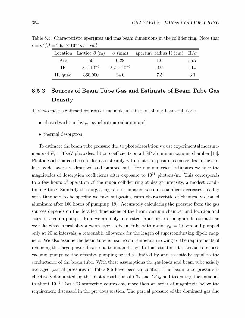
Table 8.5: Characteristic apertures and rms beam dimensions in the collider ring. Note that
ε = σ2/β = 2.65× 10⁻⁹m− rad
Location Lattice β (m) σ (mm) aperture radius H (cm) H/σ
Arc 50 0.28 1.0 35.7
IP 3× 10⁻³ 2.2× 10⁻³ .025 114
IR quad 360,000 24.0 7.5 3.1
8.5.3 Sources of Beam Tube Gas and Estimate of Beam Tube Gas
Density
The two most significant sources of gas molecules in the collider beam tube are:
• photodesorbtion by µ± synchrotron radiation and
• thermal desorption.
To estimate the beam tube pressure due to photodesorbtion we use experimental measure-
ments of Ec = 3 keV photodesorbtion coefficients on a LEP aluminum vacuum chamber [18].
Photodesorbtion coefficients decrease steadily with photon exposure as molecules in the sur-
face oxide layer are desorbed and pumped out. For our numerical estimates we take the
magnitudes of desorption coefficients after exposure to 1021 photons/m. This corresponds
to a few hours of operation of the muon collider ring at design intensity, a modest condi-
tioning time. Similarly the outgassing rate of unbaked vacuum chambers decreases steadily
with time and to be specific we take outgassing rates characteristic of chemically cleaned
aluminum after 100 hours of pumping [19]. Accurately calculating the pressure from the gas
sources depends on the detailed dimensions of the beam vacuum chamber and location and
sizes of vacuum pumps. Here we are only interested in an order of magnitude estimate so
we take what is probably a worst case - a beam tube with radius rw = 1.0 cm and pumped
only at 20 m intervals, a reasonable allowance for the length of superconducting dipole mag-
nets. We also assume the beam tube is near room temperature owing to the requirements of
removing the large power fluxes due to muon decay. In this situation it is trivial to choose
vacuum pumps so the effective pumping speed is limited by and essentially equal to the
conductance of the beam tube. With these assumptions the gas loads and beam tube axially
averaged partial pressures in Table 8.6 have been calculated. The beam tube pressure is
effectively dominated by the photodesorbtion of CO and CO2 and taken together amount
to about 10−4 Torr CO scattering equivalent, more than an order of magnitude below the
requirement discussed in the previous section. The partial pressure of the dominant gas due
8.6. CLASSICAL BEAM-BEAM INTERACTION 355
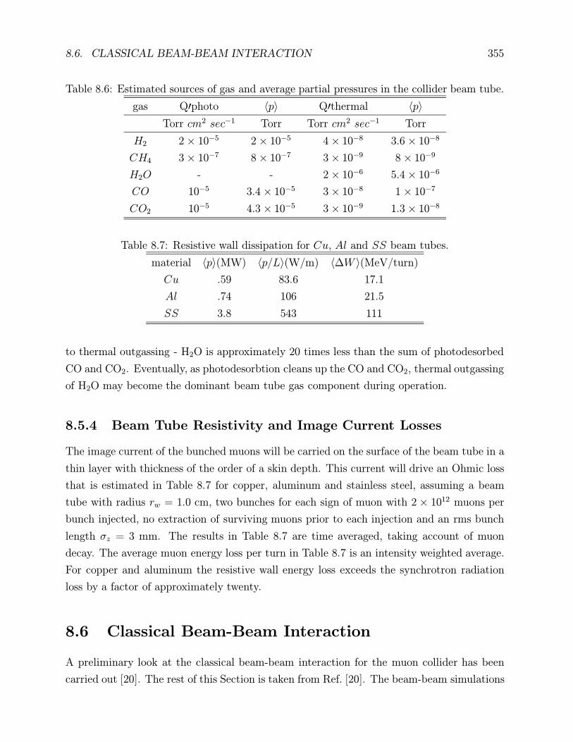
Table 8.6: Estimated sources of gas and average partial pressures in the collider beam tube.
gas Q′photo 〈p〉 Q′thermal 〈p〉
Torr cm2 sec−1 Torr Torr cm2 sec−1 Torr
H2 2× 10⁻⁵ 2× 10⁻⁵ 4× 10⁻⁸ 3.6× 10⁻⁸
CH4 3× 10⁻⁷ 8× 10⁻⁷ 3× 10⁻⁹ 8× 10⁻⁹
H2O - - 2× 10⁻⁶ 5.4× 10⁻⁶
CO 10−5 3.4× 10⁻⁵ 3× 10⁻⁸ 1× 10⁻⁷
CO2 10−5 4.3× 10⁻⁵ 3× 10⁻⁹ 1.3× 10⁻⁸
Table 8.7: Resistive wall dissipation for Cu, Al and SS beam tubes.
material 〈p〉(MW) 〈p/L〉(W/m) 〈∆W 〉(MeV/turn)
Cu .59 83.6 17.1
Al .74 106 21.5
SS 3.8 543 111
to thermal outgassing - H2O is approximately 20 times less than the sum of photodesorbed
CO and CO2. Eventually, as photodesorbtion cleans up the CO and CO2, thermal outgassing
of H2O may become the dominant beam tube gas component during operation.
8.5.4 Beam Tube Resistivity and Image Current Losses
The image current of the bunched muons will be carried on the surface of the beam tube in a
thin layer with thickness of the order of a skin depth. This current will drive an Ohmic loss
that is estimated in Table 8.7 for copper, aluminum and stainless steel, assuming a beam
tube with radius rw = 1.0 cm, two bunches for each sign of muon with 2× 10¹² muons per
bunch injected, no extraction of surviving muons prior to each injection and an rms bunch
length σz = 3 mm. The results in Table 8.7 are time averaged, taking account of muon
decay. The average muon energy loss per turn in Table 8.7 is an intensity weighted average.
For copper and aluminum the resistive wall energy loss exceeds the synchrotron radiation
loss by a factor of approximately twenty.
8.6 Classical Beam-Beam Interaction
A preliminary look at the classical beam-beam interaction for the muon collider has been
carried out [20]. The rest of this Section is taken from Ref. [20]. The beam-beam simulations

356 CHAPTER 8. MUON COLLIDER RING
for the muon collider in the incoherent classical approximation, taking into account muon
decay, show that for the nominal intensity of 2× 10¹² per bunch the beam-beam interaction
is reasonably weak and allows room for upgrading the luminosity performance. The analysis
shows that classical coherent beam-beam effects will almost certainly not spoil the beam
luminosity lifetime. The beam-beam effects become noticeable if the number of particles
is increased by a factor of three or more. These conclusions are based on the assumption
that the dynamical aperture is sufficiently large (say, 5σ or larger). For a smaller aperture
nonlinear lattice dynamics will need to be included in the calculation.
8.6.1 Introduction.
The classical beam-beam effects arise from the interaction of the particles in one beam with
the classical electromagnetic fields of the opposing beam. The fundamental dynamics is the
electromagnetic deflection of the particles. Quantum beam-beam effects deal with particle
annihilation and creation as described by relativistic quantum mechanics.
Incoherent effects are those that are well described by the interaction of a single particle
in one beam with the other beam (or by the simple superposition of such interactions), while
coherent effects are those that can only be explained by the interaction of the beams with
each other as whole.
A basic example of an incoherent classical effect is the blowup of the beam core (emittance
blowup) as the beams collide turn after turn; as a consequence of this blowup the luminosity
degrades, at least to some extent. In this case the phase space of the core particles remains
essentially structureless (approximately gaussian in the case of e+e− machines). Another
example is the development of large-amplitude tails in the particle distribution, which leads
to a decrease of the beam lifetime as the particles are gradually lost to the machine aperture.
In this case, the phase space of these large amplitude particles has a characteristic structure
that is dominated by one or more resonances arising from the combined dynamics of the
beam-beam force and the nonlinear magnetic fields of the machine. These two phenomena
dominate the beam-beam dynamics of essentially all hadron and lepton colliders built so
far. For well-tuned e+e− colliders with good dynamic aperture, these effects have vastly
different time scales: the core blowup always happens over a few damping times, while the
development of significant tails can be arranged to happen over thousands of damping times
or even longer [21].
The signature for classical coherent effects is a nontrivial structure of the phase-space
of the core particles. This space structure can arise when the tune is close to a low-order
resonance. An example of this kind of effect is the flip-flop state in e+e− colliders: in this

8.6. CLASSICAL BEAM-BEAM INTERACTION 357
case, for sufficiently high bunch current, the two beams reach an equilibrium situation in
which one of them is blown up while the other is not. This effect has been observed in
most colliders. Other coherent states that have been predicted in simulations, and perhaps
observed experimentally, are period-2 or -higher fixed points, in which the sizes of the two
beams fluctuate from turn to turn in a periodic pattern. Simulations generally show that
the time scale for these effects is of the order of 10-20 damping times [22, 23].
An example of an incoherent quantum effect for the muon collider is the reaction µ+ +
µ− → e+ + e− that can happen during the beam-beam collision. A muon can also interact
with the collective electromagnetic field of the opposing bunch to produce e+e− pairs; this
is a coherent quantum effect. The latter effect is believed to be negligible for this ring, while
the former is addressed in Sec. 8.7.
In this section, however, we will show that incoherent classical effects are weak, at least
for nominal parameter values, and that coherent classical effects are very unlikely to mate-
rialize. We will also provide rough criteria for the tolerances for the ratio β∗/σz, and for the
longitudinal displacement of off-IP collisions which can arise from RF phasing errors or from
timing errors in the injection process.
8.6.2 Physics of the Incoherent Simulation.
We carry out a simulation with the code TRS [24]. This is a “strong-strong” simulation
in which both beams are dynamical, and their emittances evolve according to their mutual
interaction. The simulation is fully six-dimensional, and the beam-beam interaction is rep-
resented as a thick lens by dividing up the bunches into 5 “slices.” We assume one bunch per
beam, and a single interaction point (IP). The beams are represented by “macroparticles”
(1024 per bunch in this case), and the machine lattice is assumed to be strictly linear, so
that it is represented by a simple phase advance matrix. This linear approximation is valid
provided that the dynamical aperture is sufficiently large (say, 5σ or larger). The three tunes
are taken as input quantities to the simulation, and we set the chromaticity to 0. From other
work, we know that the values we have chosen for the number of slices and macroparticles
are adequate for the nominal muon collider specifications [25].
The beams are described at time t = 0 by six-dimensional gaussian distributions whose
σ’s are determined by the specified nominal parameters of the collider (see Table 8.8). We
then let the bunches collide for 1000 turns, keeping track of the six-dimensional coordinates
of all the macroparticles, and measure from these the beam sizes and the luminosity at every
turn as they evolve according to the beam-beam dynamics. The code uses the so-called
“soft-gaussian approximation” by virtue of which, for the purposes of computing the beam-

358 CHAPTER 8. MUON COLLIDER RING
beam kick, the opposing bunch is assumed to have a gaussian shape in the two transverse
dimensions, albeit with time-dependent σ’s. This approximation is generally reliable pro-
vided no coherent effects appear, which is almost certainly the case for the muon collider,
as we shall discuss below. We take into account the muon decay by simply multiplying the
number of particles per bunch N in each beam by the exponential decay factor exp(−t/τ ),
where τ is the Lorentz-dilated muon decay constant.
8.6.3 Beam-beam Simulation.
Simulation Conditions.
For the purposes of this simulation, we assume parameters as listed on Table 8.8 (both
beams have the same parameters). In this table β∗ is the common value of the horizontal
Table 8.8: Muon collider parameters.
C [km] 7
E [TeV] 2
N 2× 10¹²
β∗ [mm] 3
εN [mm–mrad] 50
fc [kHz] 42.86
νx 0.57
νy 0.64
νs 1/160
σz [mm] 3
and vertical beta-functions and the same is true for the normalized emittance εN . The values
for the horizontal and vertical fractional tunes νx and νy were picked arbitrarily (the integral
part of the tune does not enter the simulation).
With these values, the beam size at the IP is
σ∗ =√β∗εN/γ = 2.74 µm (8.7)
where γ ≈ 18, 900 is the usual relativistic factor. The nominal value for the peak luminosity
is
L =fcN
2
4πσ∗2= 1.82× 1035 cm−2 s−1 (8.8)

8.6. CLASSICAL BEAM-BEAM INTERACTION 359
which is not exactly the time averaged luminosity ×1035 cm−2 s−1, as listed elsewhere in
these report.
It is worthwhile to note that the beam-beam parameter,
ξ =r0N
4πεN= 0.046 (8.9)
has a fairly typical value: In fact, beam-beam parameter values like this have been attained
or exceeded in several e+e− colliders (here r0 is the classical radius of the muon). Actually,
it is intriguing that the values of γ and ξ are similar to those in the former PEP collider,
so certain aspects of the incoherent beam-beam interaction can be expected to be similar to
those in PEP.
An important parameter in colliding rings is the damping time. Assuming that the
synchrotron energy loss per turn in the muon collider is 1 MeV, the transverse damping time
is
τx =2 TeV
1 MeV= 2× 10⁶ turns (8.10)
which is much larger than the 1000 turns’ duration of a cycle. The large difference between
these time scales is crucial in explaining some beam-beam effects.
Simulation Results.
Fig. 8.17 shows the luminosity as a function of turn number obtained under the assumption
that the muon is a stable particle. One can see that it decreases by ∼ 4% during the course
of the 1000 turns due to the incoherent emittance blowup. This fractional decrease is small
because the beam-beam parameter is modest, and because the cycle time is so small relative
to the damping time.
Fig. 8.18 shows the luminosity taking into account the finite muon lifetime. As expected
from the previous result, the curve is essentially determined by the exponential decay factor
of the muons.
Fig. 8.19 shows the luminosity vs. turn number for three values of the number of particles
per bunch N . For each value of N we carried out the simulation for three random number
seeds; thus the spread in the curves for each case gives an idea of the statistical errors of
the calculation. The bottom curves, corresponding to the nominal value of 2× 10¹², are the
same as in Fig. 8.18. The middle curves, for N = 4 × 10¹², still behave quite nominally.
However, it is clear that the curves for N = 6× 10¹² decay faster than exponentially due to
substantial emittance blowup. In addition, when we included a 10σ physical aperture in the
simulation, we observed that there were no particle losses for the first two cases, but there
was a ∼ 2% integrated beam loss for the case where N = 6× 10¹². Although this is a small

360 CHAPTER 8. MUON COLLIDER RING
2.2
2.1
2.0
1.9
1.8
Ÿ [10
35 c
m–2s
–1]
10009008007006005004003002001000
turn number
muon collider luminosity (stable muons)
Figure 8.17: Luminosity as a function of turn number assuming that the muons are stable
particles. The luminosity decreases by ∼ 4% over 1000 turns due to incoherent emittance
blowup.

8.6. CLASSICAL BEAM-BEAM INTERACTION 361
2.5
2.0
1.5
1.0
0.5
0.0
Ÿ [10
35 c
m–2s
–1]
10009008007006005004003002001000
turn number
muon collider luminosity (code TRS)
Figure 8.18: Luminosity as a function of turn number, taking into account the finite muon
lifetime. The curve follows closely the expected exponential decay dependence.

362 CHAPTER 8. MUON COLLIDER RING
20
15
10
5
0
Ÿ [10
35 c
m–2s
–1]
10009008007006005004003002001000
turn number
N= 6 × 10¹²
N= 4 × 10¹²
N= 2 × 10¹²
muon collider luminosity(3 values for N and 3 random seeds for each)
Figure 8.19: Luminosity as a function of turn number for three different values of the number
of particles per bunch N . For each case we show three runs, each corresponding to a different
random number seed; the spread of the curves for each case gives an idea of the statistical
accuracy of the calculation.

8.6. CLASSICAL BEAM-BEAM INTERACTION 363
fraction of particles, it is reasonable to interpret this as a symptom that the beam-beam
strength is being pushed beyond a prudent limit, and the results of this simulation cannot
be taken as a reliable guide. When this kind of behavior is seen, it is likely that other
detrimental effects, not included in this simulation, will become important and will lead
to even more unfavorable behavior. We conclude from this calculation that the incoherent
beam-beam effect is weak for the nominal current and that there is some room for upgrading
the luminosity by increasing the bunch current by a factor of ∼ 2 but not more than this.
8.6.4 Other Classical Beam-Beam Issues.
Coherent Effects.
Classical coherent effects significantly distort the phase space of the beam core away from
the gaussian shape. This distortion may be static or time dependent, and leads to luminosity
degradation; thus, despite the theoretical interest of these effects, in practice one wants to
identify the conditions under which they appear in order to avoid them.
Simulation studies for e+e− machines [22] show that these effects materialize for beam-
beam parameter values ∼> 0.05 and for isolated values of the fractional tune where certain
low-order resonances dominate the dynamics. More importantly, these results also show
that coherent effects take a long time to develop, on the order of 10 damping times or more,
simply because it takes a long time for the particles to redistribute in phase space in order
to give rise to a clear structure. At the beginning of the simulation (the time scale being
set by the damping time), there is no hint of structure, and the phase space distribution
is essentially gaussian. This is the situation relevant to the muon collider, since the cycle
time is a tiny fraction of the damping time. Furthermore, these results are obtained in the
zero-bunch-length approximation, and there are indications [26] that a nonzero bunch length
strongly suppresses coherent effects. Although more research is needed, and experimental
work under controlled conditions needs to be carried out to confirm the simulation results,
we can safely conclude from presently available information that these effects are unlikely to
appear in the muon collider.
Beam Tails and Beam-Beam Lifetime.
While the beam core determines the luminosity of a collider, the beam tails determine the
beam lifetime. The beam core, typically understood to be the phase space region within
∼ 3σ of the center, is not very sensitive to nonlinear machine resonances because the lattice
magnetic fields are typically quite linear in this region. On the other hand, the beam tail

364 CHAPTER 8. MUON COLLIDER RING
extends out to sufficiently large amplitudes so that its dynamics is sensitive to an interplay
[27] of beam-beam and lattice nonlinearities (beam-gas scattering can also come into play in
subtle ways, although typically it has a clearer effect on the beam core).
There has been much recent progress in understanding and properly simulating the beam
tails in e+e− colliders. These new tools make use of a clever algorithm by which the brute-
force tracking is “accelerated” by 2-3 orders of magnitude in order to determine the particle
density and flux at large amplitudes (up to ∼ 20σ or so) [28, 29]. From the particle flux one
can then determine the lifetime, given the physical aperture. For the purposes of this article,
one can roughly summarize the conclusions as follows: for a lattice with larger dynamic
aperture (meaning 5σ or more), and for reasonable values of the beam-beam parameter
(meaning 0.05 or less), it is not difficult to find working points for which the beam-beam
lifetime is of the order of 107−109 turns (however, the lifetime can degrade by several orders
of magnitude by relatively small changes in these parameters). In any case, the instability of
the muon will almost certainly dominate the beam lifetime, so at least from this perspective,
the beam tails will not be important.
Thus the beam tails might be much more important for other reasons such as background
and radiation. The important thing, therefore, is to specify the maximum acceptable number
of muons that can hit the vacuum chamber during the 1000 turns of a cycle. Such a criterion
is closely related to that of the dynamic aperture. In the above-mentioned e+e− simulations,
the damping time, typically of order 103−104 turns, also plays an important role. The muon
collider, as mentioned earlier, essentially has no damping, so in this respect it is akin to proton
colliders. It seems therefore that the tracking tools used to determine the dynamic aperture
of such machines are the right ones for this case, provided they are augmented to include
a beam-beam element. Such a code development should be relatively simple, although the
analysis will likely involve many iterations.
Hourglass Effect for Centered Collisions.
Because of the geometrical divergence of the beams at the IP, the luminosity is actually
smaller than the nominal value given by Eq. (8.8), which represents the limiting value as
the bunch length σz → 0. As σz grows at fixed β∗, the luminosity decreases due to this
“hourglass effect.” Neglecting all dynamical effects, this purely geometrical reduction factor
is given, for symmetric round gaussian beams, by the formula [30]
L(σz)
L(0)=
∞∫−∞
dt√π
e−t2
1 + (t/tx)2=√π tx e
t2x erfc(tx) (8.11)

8.6. CLASSICAL BEAM-BEAM INTERACTION 365
where tx ≡ β∗/σz. For the muon collider, tx has been chosen to be unity; β∗/σz] It can be
shown that the luminosity degrades quickly as σz increases.
Hourglass Effect for Longitudinally-Displaced Collisions.
By virtue of the hourglass effect, the luminosity also degrades if the bunches collide at a point
away from the optical IP. If the central collision is longitudinally displaced by a distance sc
from the IP (but the bunches still collide transversely head-on), the luminosity reduction
factor is given by [30]
L(sc, σz)
L(0, 0)=
∞∫−∞
dt√π
e−(t−tz)2
1 + (t/tx)2(8.12)
where tz ≡ sc/σz and tx is the same as above. In Fig. 8.20 we show the luminosity reduction
1.0
0.8
0.6
0.4
0.2
0.0
Ÿ(s
c)/Ÿ
(0)
3.53.02.52.01.51.00.50.0normalized displacement, sc/σz
Luminosity reduction factor (static hourglass effect) due to longitudinally-displaced collisions
symmetric round beams with β∗/σz=1
Figure 8.20: The hourglass luminosity reduction factor when the collisions are longitudi-
nally displaced from the IP by a distance sc, plotted as a function of sc/σz. Note that the
normalization is L(sc = 0, σz = 3 mm), i.e. the nominal value.

366 CHAPTER 8. MUON COLLIDER RING
factor as a function of tz (please note that in this figure we have normalized the reduction
factor to L(0, σz) and not to L(0, 0) as in Eq. (8.12)). One can see that the luminosity
degrades quickly when the collision point is farther away than ∼ 1σz from the optical IP.
This gives an idea of the RF phasing errors or injection timing errors that can be tolerated.
8.6.5 Summary
We have carried out some basic beam-beam simulations for the muon collider in the inco-
herent classical approximation, taking into account the muon decay. We conclude that the
beam-beam interaction is reasonably weak and allows room for upgrading the luminosity
performance. We have argued that classical coherent beam-beam effects will almost cer-
tainly not materialize, and neither will long tails that might spoil the beam lifetime. We
have provided some very basic constraints on the ratio β∗/σz and on off-center collisions
arising from the hourglass effect. Finally, we will attempt to prioritize work that remains to
be done.
From the perspective of the classical beam-beam dynamics, the four key features that
distinguish the muon collider are:
1. A relatively modest beam-beam parameter, ξ = 0.046.
2. A short cycle of 1000 turns.
3. A long damping time, τx = 2× 10⁶ turns.
4. Unstable muons.
The first feature is shared with many e+e− colliders; the second makes this collider not
too different from single-pass colliders; the third one makes it resemble a hadron collider;
and the fourth, of course, is unique to this machine. It is fair to say that one can under-
stand all features of the classical beam-beam interaction from the interplay of these four
characteristics.
We have shown by means of beam-beam simulations that the classical incoherent beam-
beam effect is quite weak for the muon collider in its present design. From this perspective,
there is room for upgrading the luminosity, if necessary, by increasing the bunch current by
a factor of 2 or so but not more than this.
We have argued that coherent classical beam-beam effects are very unlikely to materialize.
We have also argued that beam tails are unlikely to affect the luminosity lifetime. Un-
doubtedly there will be a certain number of large-amplitude muons that will hit the chamber,

8.7. QED EFFECTS AT THE INTERACTION REGION 367
and it seems important to establish this number. This issue is closely related to the determi-
nation of the dynamic aperture, and single-particle tracking tools used for hadron colliders,
duly augmented to include the beam-beam interaction, seem appropriate to address this
issue.
From purely geometrical considerations, we have provided a rough estimate (probably a
lower bound) of the sensitivity of the luminosity to the ratio β∗/σz and to the longitudinal
displacement of the collision point from the IP. These estimates yield fairly standard results:
one should not choose the ratio β∗/σz below ∼ 1 or so, and one should not allow collisions
to be displaced from the optical IP by more than ∼ 1σz in either direction.
Much work remains to be done to firm up the limits imposed by the beam-beam inter-
action. Here is a brief suggested list, roughly in order of priority:
1. Develop a dynamic aperture tool by augmenting a single-particle tracking code to
include a “beam-beam lens.”
2. Track specific lattices, including all nonlinearities, and estimate from the results the
number of muons that hit the vacuum chamber during 1000 turns; iterate this process
to determine tolerances on machine nonlinearities.
3. Establish the sensitivity of the beam-beam interaction to longitudinal and transverse
alignment errors and jitter.
8.7 QED Effects at the Interaction Region
A significant source of e+e− pairs in the µ+µ− collider is the incoherent process µ+µ− →
µ+µ−e+e− which has a cross section about 10 mb (at a muon energy 2 TeV). An analysis of
the energy distribution of the pairs shows that they may generate a significant and undesir-
able background in the detector. The bulk of this Section is taken from [32]. The detector
design chapter addresses this in further detail.
Coherent pair production in the muon collider occurs as an individual muon interacts with
the magnetic field of the opposing bunch at the IP. It is now believed to be an insignificant
effect in the parameter regime of the collider. [32].
Since the heat deposition in the collider creates a limit on the number of muons that can
hit the wall each turn, we must investigate the energy spectrum of those muons that create
pairs, and follow their trajectories. This must be done for muons that pair produce at the
IP and for those that decay naturally during the ≈ 1000 turn storage. The characteristic

368 CHAPTER 8. MUON COLLIDER RING
magnetic field of bunch at the collision point is, for the parameters of Table 8.1,
B ∼eN
2σxσz∼ 0.5× 10³ T. (8.13)
The asymptotic cross section for the production of e+e− pairs at the collision of charged
particles was first obtained 60 years ago [33]. A precise treatment of this process, along with
numerous references, are can be found in Ref. [34].
A detailed analysis of the main features of the pair production process pp→ ppe+e− , with
numerical estimates, has been considered in detail [35]. This process is similar to the pair
production in the muon ring. The equations in Ref. [35] are valid for the muon collider ring,
with the evident changes in notation, and some numerical estimates should be reconsidered
due to a much higher Lorentz factor in the muon collider.
Some rough estimates of the process are:
1) The total cross section of the process is [36]:
σ ≈ 10 mb. (8.14)
2) The main mechanism for pair creation is the two–photon production of e+e− pairs via
the collision of two virtual photons which are emitted by the muons. The main features of
process can be obtained with the equivalent photon (Weizsacker–Williams) approximation
(EPA). The spectra of virtual photons are found from an analysis of Feynman diagrams.
Their dependence on the energy ω and virtuality Q2 has the form
dn(ω,Q2) =α
π
dx
x
dQ2
Q2
[1− x+
x2
2− (1− x)
Q2min
Q2
]; (8.15)
Q2 ≥ Q2min = m2
µ
x2
1− x. (8.16)
where x = ω/E and the last inequality is obtained easily from kinematics.
The cross section for the subprocess γγ → e+e− has a maximum when W 2 ≈ 8m2e,
where W is the effective mass of the produced system. Therefore, the effective mass of the
produced e+e− system is near threshold, and the transverse momenta of produced particles
is ∼ me. Furthermore, this cross section decreases quickly with the growth of the virtuality
Q2 above m2e. In other words, the main contribution to the cross section is in the region
m2e > Q2 > Q2
min.
Now, with Eq. (8.16), we obtain the limit for the energy of the photons:
x =ω
E<me
mµ
⇒ ω < γme. (8.17)

8.7. QED EFFECTS AT THE INTERACTION REGION 369
Therefore, — in accordance with the naive expectations — the Lorentz–factor of the pro-
duced e+e− pair cannot be higher than that of the initial muon.
An integration of Eq. (8.15) over virtuality gives the number of equivalent photons that
are produced:
dn(ω) =2α
π
dx
x
[ln
(me
mµx
)−
1
2
]. (8.18)
Note, that this quantity is much lower than that for the two-photon production of muons or
hadrons, which is
∼ (2α/π)(dx/x) ln(1/x). (8.19)
The source of this difference is the much higher upper limit of effective virtualities for these
processes, which determined by the much higher scale of the Q2 dependence for these sub-
process. (For more detail discussion see Ref. [34].)
3) The produced pairs are distributed uniformly in the rapidity scale. The distribution
over the total energy of pair ε is
dσ =
56α4
9πm2e
dkzε
[ln2 γ − ln2 ε
me
]at ε < γme;
∼ α4
m2e
dεε
(γmeε
)2at ε > γme.
(8.20)
Here kz is the longitudinal momentum of the pair, |kz| ≈ ε.
The mean energy of a pair is ∼ 2meγ/ ln γ ∼ 2 GeV. In accordance with Eq. (8.14),
the number of pairs produced is about 105 per bunch collision, i.e. about 108 during the
luminosity lifetime in the ring. Therefore, the entire energy losses due to the discussed
process are about 2× 10⁻⁶% of the muon energy, i.e. negligible.
4) The distribution over the energy of one electron ε1, emitted along the motion of initial
µ+, has the form
dσ =56α4
9πm2e
dk1z
ε1
[ln2 γ − ln2 ε1
me
](ε1 me). (8.21)
Here k1z is the longitudinal momentum of the electron. The effective mass of produced pairs
is near the threshold and their total transverse momentum is very low. Therefore, the bulk
of the electrons and positrons move initially in the same direction as the beam.
However, as was pointed out by Palmer [37], the created electrons are deflected by the
magnetic field of the opposing muon bunch and may fly into the detector. Detailed studies
of this potentially serious problem are being carried out by the detector group.

370 CHAPTER 8. MUON COLLIDER RING
8.8 Single Bunch Collective Effects
Introduction
The design of a high luminosity (2.5× 1030cm−2 per collision) muon collider ring, from the
perspective of the physics of collective effects, has some unique features which need to be
examined. (1) Muons have a very short life time: τµ ' 41.6 ms at 2 TeV, corresponding to
a thousand ”effective” turns in a ring with the circumference of 7 kilometers. (2) The bunch
is short: σz = 3 mm. (3) The bunch has a large charge: N = 2× 10¹². (4) The momentum
compaction α is very small: α ≤ 10−6. These features lead us to some unusual aspects of
the ring operation: The intense bunch required for the high luminosity makes instabilities
likely and very small α requires careful estimations of nonlinear corrections to the particle
orbit and to the collective dynamics.
The longitudinal equations motion of a particle in a circular machine are
z′ = −ηδ, (8.22)
δ′ = K(z), (8.23)
where z is the oscillation amplitude with respect to the bunch center, ′ = d/ds, s measures
distance around the ring, δ = dp/p, η = α − 1/γ2, α = pdC/Cdp. The force K(z) that a
particle experiences can be modeled as having two parts, one is due to the radio frequency
(rf) cavities, and the other is from the wake fields generated by the interaction between beam
and cavities or other components of its electromagnetic environment,
K(z) = Krf (z) +Kwake(z), (8.24)
where
Krf (z) =eVrf (z)
CE, (8.25)
and
Kwake(z)=F‖wake(z)
E(8.26)
=−r0
γC
∫ ∞zdz′ρ(z′)W ′
0(z − z′).
In Eq. 8.26, T0 = 2π/ω0 = C/c, E = γmµc2, r0 = e2/mµc
2, N =∫dz′ρ(z′), and C = 2πR is
the circumference of the collider ring.
In Eq. 8.25, when the amplitude of synchrotron motion is small compared with the rf
wavelength such that the rf voltage is linearized as Vrf (z) = V sin(ωrfz/c) ≈ V ωrfz/c and

8.8. SINGLE BUNCH COLLECTIVE EFFECTS 371
the momentum compaction is expanded as η = η1 + η2δ+ η3δ2 (with the contributions from
η2 and η3 negligible), the synchrotron oscillation frequency is ωs0 =(eη1 c ωrf V /CE
)1/2.
The transverse equation of motion is
y′′(z, s) +ω2β
c2y(z, s) = −
Nr0
γC
∫ ∞z
dz′ρ(z′)W1(z − z′)y(z′, s). (8.27)
A simulation code that solves these equations has been developed to study collective
phenomena in the ring.
Static Effects
As a starting point we consider a TESLA-like rf system, and a quasi-isochronous lattice which
has η1 = 10−6, with the contributions from η2 and η3 negligible. With a bunch length σz = 3
mm, σδ = 1.5 × 10⁻³ rms energy spread and an 130MV of L-band rf, the muon bunch is
matched to the rf and a muon would undergo ∼ .56 synchrotron oscillations in one thousand
turns. The beam-loading factor, defined as 4E/particle/Vrf , is 10% when only the cavity
losses are included. Resistive losses are estimated to roughly equal the rf losses, but have
not been explicitly included in our calculation. Other losses have not been calculated, and
may lead to an increase in the rf voltage. These loses will need to be replenished even if the
momentum compaction is reduced to η1 = 10−7, as may be required because of microwave
instabilities.
Parasitic Loss The beam loses energy when it experiences the impedance of the rf cavities.
The rf impedance is modeled by using Wilson’s scaling formula for the longitudinal wake
function [15]. Explicitly, choosing as starting point TESLA’s rf structure, we use
W ′0(z < 0) = 226(
fTESLA
fSLAC)2 × exp[−(|z|
fTESLA
0.1839fSLAC)0.605], (8.28)
where fTESLA = 1.3GHz and fSLAC = 2.856GHz. Causality requires: W ′0(z) = 0 for z > 0.
The simulation code computes the wake voltage Vwake(z) =∫∞z dz′ρ(z′)W ′
0(z − z′), and the
energy loss
4E = −∫∞−∞ dzρ(z)
∫∞−∞ dz
′ρ(z′)W ′0(z − z′).
The peak wake voltage is further scaled from Wilson’s formula to give parasitic cavity
losses 17V/pC/m at 1σz for a Gaussian beam. This choice of wake amplitude makes it
consistent with the TESLA rf cavity studies[16].
The effects of radiation and diffusion of muons are small in a muon lifetime (radiation
damping time ∼ 106 turns), so that, unlike in electron rings, equilibrium is not achieved by
radiation damping. The intense muon bunch generates significant wakes, and these wakes

372 CHAPTER 8. MUON COLLIDER RING
Figure 8.21: Scaled rms bunch size and rms energy-spread vs. turn, where at injection:
z(0) = 3mm, δ(0) = 0.15%.
in turn cause significant changes in the vacuum rf potential. This potential-well distortion
causes oscillation of the bunch center, bunch size, and distribution function in the rf bucket.
Fig. (8.21) shows the oscillations of the rms bunch size and bunch energy spread. The
bunch centroid tends to move forward to a higher rf voltage, so that the energy loss can be
compensated. As a result, it makes a counter-clockwise rotation in δ − z phase space, as
shown in Fig. (8.22). The parasitic losses from the rf and motion of the bunch centroid are
compensated for by injecting the beam with an rf phase offset of 0.082 radians with respect
to the bunch center, as shown by the dashed line in Fig. (8.22).
Coherent Effects
Microwave Instability The microwave instability is presently considered the most serious
challenge to maintaining a short bunch. Presently studies are underway to examine the limits
this instability places upon Z/n. The ring parameters obviously will not satisfy the Keil-
Schnell criterion for stability, but rather hope to reduce the growth rate to an acceptable
amount during the ∼ 1000 turns of beam storage. The microwave instability growth rate
is weaker at smaller η values, and the instability may require the lattice to operate at
η = 10−7. At this value of η the particles barely move longitudinally, and the possibility and
consequences of compensating for the wake potential with rf are being considered. In the
absence of longitudinal motion the main problem is to maintain an energy spread within the
longitudinal acceptance of the ring.

8.8. SINGLE BUNCH COLLECTIVE EFFECTS 373
Figure 8.22: Center of energy-spread vs. center of bunch size. The rf phase offsets are,
φ = 0, 0.082 radian, for the solid line and dashed line, respectively.
Beam-Break-Up For times much shorter than the synchrotron oscillation period, parti-
cles are almost frozen longitudinally in the bunch, and the transverse wakefield dynamics has
many similarities with that in a linac [10, 40]. In a linac, the transverse wake field generated
by the head of the bunch drives the tail, causing Beam-Break-Up (BBU). A dimensionless
parameter that characterizes the BBU strength is [17]
Υ(z) = Nr0|〈W1(z)〉|c/4ωβγ, (8.29)
where ωβ is the betatron angular frequency, and 〈W1(z)〉 =∫∞z dz′W1(z − z′)ρ(z′) is the
convoluted total transverse wake function. The tail of an off-axis bunch doubles its offset
in a number of turns n ' 1/Υ, so long as n 1/2νs, i.e., when the particle’s synchrotron
motion can be ignored.Here νs is the synchrotron tune.
Simulation results for the BBU-like instability using a resonator model are shown in Fig.
(8.23). The main point is that while the motion is unstable, it is easily cured with only a
small amount of BNS damping, as discussed below.
Head-Tail Instabilities When the transverse oscillation frequency is modulated by the
energy oscillation, the chromaticity, which is the slope of the frequency to the energy, builds
up a head-tail phase that bootstrap from the first half synchrotron period to the next,
and drives the system into instability without threshold. This head-tail instabilities occurs
in both transverse and longitudinal motion [41]. The effect of transverse head-tail (THT)
instability is small when η1 ≤ 10−6.

374 CHAPTER 8. MUON COLLIDER RING
For the longitudinal motion, the longitudinal chromaticity involves the non-linear part
of slip factor: η2. The bucket height and the growth time of the longitudinal head-tail
(LHT) instability are both proportional to η1/η2. Different design of the lattice lead to very
different results for the geometry of bucket and the collective effects. It is assumed here that
the contributions of η2 and η3 to the dynamics are sufficiently small, even if η1 = 10−7, that
they can be neglected. Simulations indicate that the longitudinal head-tail instability can
be controlled by not allowing η2/η1 to become too large. Detailed studies of the acceptable
parameter ranges are underway.
BNS Damping
Since the synchrotron radiation radiation damping is negligible and the ring is quasi-isochronous
(so that the effect of Landau damping is very small), neither of these are likely to may damp
collective instabilities. ”External” mechanisms, such as BNS damping, may be needed to
stabilize the system. The BNS damping can be achieved by a radio frequency quadrupole
(RFQ), which introduces a betatron tune spread across the bunch such that the bunch tail
experiences a larger betatron focusing than the bunch head [17]. Fig. (8.23) shows that the
BBU-like instability is stabilized when a small BNS tune spread is applied to the beam. One
should note that, the BNS damping works for the ring only when the potential-well distor-
tion is compensated by rf phase offset, such that the bunch shape remains approximately
stationary. This is because the amount of BNS tune spread obtained from the prescribed for-
mula 4νβ(z)/νβ = Υ(z)/πνβ, involves the bunch’s density profile. To maintain the correct
BNS detuning condition, the bunch shape should not seriously deviate from its initial state;
otherwise, one needs to adjust the BNS tune spread accordingly. Investigations are underway
to determine if such an rf quadrupole is feasible. In addition, the transverse chromaticity,
which causes betatron tune spread, may provide some Landau damping of the instability.
Conclusions
Various single bunch collective effects have been examined. The longitudinal microwave
instability is, at present, seen to be the greatest threat to maintaining the bunch length.
Operation at η1 = 10−7 is being considered, along with ideas for compensating the energy
variation induced by the longitudinal wake. The transverse strong head-tail instability with
the small η is seen to be BBU-like and can be stabilized by BNS damping. Other instabilities
are not believed to be severe over the short storage times.

8.8. SINGLE BUNCH COLLECTIVE EFFECTS 375
Figure 8.23: Blow up of the rms beam size, due to the BBU-like effect, where 1/νs = 1784.
Note that Rs/Q = 18225(Ω), bcavity = 1.3cm are used for the resonator model, injection error
∆y = 0.2cm, and Υ(1σz) ' 0.017. After BNS damping is applied, 4νβ(1σz)/νβ ' 6× 10⁻⁵,
the beam size fluctuates only slightly around 1 cm, a nominal injection beamsize.

376 CHAPTER 8. MUON COLLIDER RING

Bibliography
[1] A. Garren, et al., Design of the Muon Collider Lattice: Present Status, to appear in
Proc. of the San Fransisco Workshop on the Physics of Muon Colliders, 1996.
[2] N.M. Gelfand, A Prototype Lattice Design for a 2 TeV µ+µ− Collider, Fermilab Re-
port TM-1933, 1995; King-Yuen Ng, presentation at the 9th Advanced ICFA Beam
Dynamics Workshop, Montauk, New York, Nov. 1995; D. Trbojevic, et al., Design of
the Muon Collider Isochronous Storage Ring Lattice, Proceedings of the Micro Bunches
Workshop, Eds. E. Blum, M. Dienes and J. Murphy, Conference Proceedings 367 (1996)
; C. Johnstone and K.-Y. Ng, Interaction Regions for a Muon Collider , ibid.
[3] Juan C. Gallardo and Robert B. Palmer, Final Focus System for a Muon Collider A
Test Model, to appear in Proc. of the San Fransisco Workshop on the Physics of Muon
Colliders, 1996.
[4] S. Y. Lee, K. Y. Ng and D. Trbojevic, Minimizing dispersion in flexible-momentum-
compaction lattices, Phys. Rev. E 48, 3040 (1993)
[5] R. B. Palmer, Beam Dynamics in a Muon Collider Beam Dynamics Newsletter, No.8
(1994) 27, Eds. K. Hirata, S. Y. Lee and F. Willeke.
[6] F. Zimmermann, et al., A Final Focus System for the Next Linear Collider, SLAC-PUB-
95-6789, June 1995, presented at PAC95, Dallas, Texas, May 1-5, 1995; to be published;
O. Napoly, CLIC Final Focus System: Upgraded version with increased bandwidth and
error analysis, DAPNIA/SEA 94 10, CLIC Note 227, 1994.
[7] K. Brown, A conceptual Design of Final Focus Systems for Linear Colliders, SLAC-
PUB-4159, (1987).
[8] R. Brinkmann, Optimization of a Final Focus System for Large Momentum Bandwidth,
DESY-M-90-14, 1990.
377

378 BIBLIOGRAPHY
[9] K. Johnsen, Effects of Nonlinearities on Phase Transition, Proc. CERN Symposium on
High Energy Accelerators and Pion Physics, Geneva, Vol.1, 106 (1956).
[10] K.Y. Ng, Higher-Order Momentum Compaction for a Simplified FODO Lattice and
Comparison with SYNCH, Fermilab Internal Report FN-578, 1991.
[11] L. Schachinger, private communication.
[12] N. V. Mokhov, “The mars Code System User’s Guide, version 13 (95)”, FNAL–FN–628
(1995).
[13] N. V. Mokhov and S. I. Striganov, Simulation of Backgrounds in Detectors and En-
ergy Deposition in Superconducting Magnets at µ+µ− Colliders, Proc. of the 9th Ad-
vanced ICFA Beam Dynamics Workshop, Ed. J C. Gallardo, Conference Proceedings
372 (1996); also Fermilab–Conf–96/011 (1996).
[14] Perry Wilson, SLAC, private communication).
[15] Perry Wilson, SLAC-PUB-2884 (Rev.), ”High Energy Electron Linacs”, 1991, p. 77)
[16] A. Mosnier, DAPNIA-SEA-92-06, CE Saclay.
[17] Alex Chao, ”Physics of Collective Beam Instabilities in High Energy Accelerators”, Eqn.
2.194, p. 118.
[18] A. Mathewson, E. Alge, O. Grobner, R. Souchet and P. Strubin, J. Vac. Sci. Technol.
A5, 2512 (1987).
[19] A. Mathewson, C. Reymermier and S. Zhang, CERN Vac. Tech. Note 95-22 (1995).
[20] M. Furman, The Classical Beam-Beam Interaction for the Muon Collider: a First Look
, BF-19/CBP-Note-169/LBL-38563, April 1996.
[21] D. Rice, Observations of the Beam-Beam Effect in PEP, SPEAR and CESR, Proc. Third
Advanced ICFA Beam Dynamics Workshop (Beam-Beam Effects in Circular Colliders),
I. Koop and G. Tumaikin, eds., Novosibirsk, May 29–June 3, 1989, p. 17.
[22] S. Krishnagopal and R. Siemann, Coherent Beam-Beam Interaction in Electron-Positron
Colliders, Phys. Rev. Lett. 67, pp. 2461–2464 (1991).
[23] R. Siemann, The Beam-Beam Interaction in e+e− Storage Rings, SLAC-PUB-6073,
March 1993; Proc. Joint US-CERN School on Particle Accelerators: Frontiers of Particle

BIBLIOGRAPHY 379
Beams, Factories with e+e− rings, Benalmadena, Spain, October, 1992, pp. 327–363
(Springer Verlag Lecture Notes in Physics no. 425, M. Dienes, M. Month, B. Strasser
and S. Turner, eds.).
[24] J. L. Tennyson, undocumented code TRS, 1989.
[25] M. A. Furman, Beam-Beam Issues in Asymmetric Colliders, LBL-32561/UC-414/ESG-
205/ABC-77, July 1992, invited talk presented at the Conference on B Factories: The
State of the Art in Accelerators, Detectors and Physics, Stanford, CA, April 6–10,
1992 (proceedings, p. 109); invited talk presented at the Washington APS Meeting,
Washington, DC, April 18–23, 1992.
[26] R. H. Siemann, private communication.
[27] D. Shatilov and A. Zholents, Lifetime and Tail Simulations for Beam-Beam Effects in
PEP-II B Factory, to be published in the Proc. 1995 Particle Accelerator Conference
and International Conference on High Energy Accelerators (Dallas, Texas, May 1–6,
1995); LBL-36484.
[28] J. Irwin, Simulation of Tail Distributions in Electron-Positron Circular Colliders,
SLAC-PUB-5743, February 1992; Proc. Third Advanced ICFA Beam Dynamics Work-
shop (Beam-Beam Effects in Circular Colliders), I. Koop and G. Tumaikin, eds., Novosi-
birsk, May 29–June 3, 1989, p. 123.
[29] T. Chen, J. Irwin and R. Siemann, Simulation of the Beam Halo from the Beam-Beam
Interaction, SLAC-PUB-6379, October, 1993; Phys. Rev. E49, March 1994, p. 2323.
[30] This is an old subject; a relatively recent reference is: M. A. Furman, Hourglass Ef-
fects for Asymmetric Colliders, LBL-30833, Proc. 1991 Particle Accelerator Conf., San
Francisco, May 6–9, 1991, p. 422.
[31] R.B. Palmer. Beam Dynamics Newsletter. # 8 (1995); Report at 3-rd Int. Conf. Physics
Potential & Developments of µ+µ− Colliders, San Francisco, December 13–15, 1995.
[32] I. Ginzburg, The e+e− pair production at µ+µ− collider., submitted for publication.
[33] L.D. Landau, E.M. Lifshitz. Phys. Zs. Sovjet 6 (1934) 244.
[34] V.M. Budnev, I.F. Ginzburg, G.V. Meledin and V.G. Serbo. Phys.Rep. 15C (1975) 181.
[35] V.M. Budnev, I.F. Ginzburg, G.V. Meledin, V.G. Serbo. Phys. Lett. 39B (1972) 526;
Nucl.Phys. B63 (1973) 519.

380 BIBLIOGRAPHY
[36] C. Racah. Nuovo Cim. 14 (1937) 93.
[37] R.B. Palmer. Private communication.
[38] A.I. Nikishov, V.I. Ritus. Sov. ZhETF 46 (1964) 776.
[39] K.Y. Ng, Beam Stability Issues in a Quasi-Isochronous Muon Collider, Proceedings of
the 9th Advanced ICFA Beam Dynamics Workshop, Ed. J. C. Gallardo, AIP Press,
Conference Proceedings 372 (1996).
[40] W. H. Cheng, A. M. Sessler, and J. S. Wurtele, Studies of Collective Instabilities, in
Muon Collider Rings, Proceedings of the 9th Advanced ICFA Beam Dynamics Work-
shop, Ed. J.C. Gallardo, AIP Press, to be published.
[41] C. Pellegrini, Nuovo Cimento 64A, 447 (1969). B. Chen and A. W. Chao, Particle
Accelerators, vol. 43(1-2), pp77-91,1993.
[42] W.-H.Cheng, A.M. Sessler and J.S. Wurtele, ”Alternating chromaticity: a damping
mechanism for the transverse head-tail instability”, in prepariation.

Contributors
• J. S. Wurtele, (Univ. California Berkeley) Editor
• W-H Cheng (LBNL)
• E. Courant (BNL)
• M. Furman (LBNL)
• J. Gallardo (BNL)
• A. Garren (LBNL)
• I. Ginzburg (Inst. of Math., Novosibirsk)
• M. Green (LBNL)
• C. Johnstone (FermiLab)
• N. Mokhov (FermiLab)
• K-Y. Ng (FermiLab)
• K. Oide (KEK)
• R. Palmer (BNL)
• J. Peterson (LBNL)
• A. M.Sessler (LBNL)
• D. Trbojevic (BNL)
• W. Turner (LBNL)
• E. Willen (BNL)

382 BIBLIOGRAPHY

List of Figures
8.1 The complete collider ring layout. . . . . . . . . . . . . . . . . . . . . . . . . 329
8.2 Betatron (βx solid-line; βy dash-line) and dispersion (dot-line) functions of an
arc-module. . . . . . . . . . . . . . . . . . . . . . . . . . . . . . . . . . . . . 331
8.3 Betatron (βx solid-line; βy dash-line) and dispersion (dot-line) functions of a
dispersion suppressor module. . . . . . . . . . . . . . . . . . . . . . . . . . . 332
8.4 Experimental insert (half) with extremely small beta function at the IP. . . . 333
8.5 Utility insertion (half) . . . . . . . . . . . . . . . . . . . . . . . . . . . . . . 334
8.6 Fractional tunes Qx,y vs ∆pp
. . . . . . . . . . . . . . . . . . . . . . . . . . . 335
8.7 Beta function β∗ vs ∆pp
. . . . . . . . . . . . . . . . . . . . . . . . . . . . . . 335
8.8 Chromaticity vs ∆pp
. . . . . . . . . . . . . . . . . . . . . . . . . . . . . . . 336
8.9 Momentum compaction α vs ∆pp
. . . . . . . . . . . . . . . . . . . . . . . . 336
8.10 Amplitude dependent tune shift dQdε
vs ∆pp
. . . . . . . . . . . . . . . . . . . 337
8.11 A cold iron 8.5 T cosine theta dipole with a 65 mm thick tungsten liner at
300 K . . . . . . . . . . . . . . . . . . . . . . . . . . . . . . . . . . . . . . . 343
8.12 Two versions of an 8.5 T cold iron split dipole that would have less than 0.1%
of the muon decay power deposited within the superconducting coils . . . . . 344
8.13 A quadrupole design that avoids superconductor on the midplane . . . . . . 345
8.14 Azimuthal distribution of power density in the first SC cable shell in the
collider arc for different tungsten liners inside the aperture for 2 TeV muon
beam decays . . . . . . . . . . . . . . . . . . . . . . . . . . . . . . . . . . . . 346
8.15 Maximum and azimuthal averaged power density in the first SC cable shell in
the collider arc vs tungsten liner thickness for 2 TeV muon beam decays. . . 347
8.16 Power dissipation in the arc magnet components vs tungsten liner thickness
for 2 TeV muon beam decays. . . . . . . . . . . . . . . . . . . . . . . . . . . 348
8.17 Luminosity as a function of turn number assuming that the muons are stable
particles . . . . . . . . . . . . . . . . . . . . . . . . . . . . . . . . . . . . . . 360
8.18 Luminosity as a function of turn number, taking into account the finite muon
lifetime . . . . . . . . . . . . . . . . . . . . . . . . . . . . . . . . . . . . . . . 361
383

8.19 Luminosity as a function of turn number for three different values of the
number of particles per bunch N . . . . . . . . . . . . . . . . . . . . . . . . 362
8.20 The hourglass luminosity reduction factor when the collisions are longitudi-
nally displaced from the IP by a distance sc, plotted as a function of sc/σz . 365
8.21 Scaled rms bunch size and rms energy-spread vs. turn . . . . . . . . . . . . . 372
8.22 Center of energy-spread vs. center of bunch size . . . . . . . . . . . . . . . . 373
8.23 Blow up of the rms beam size, due to the BBU-like effect, where 1/νs = 1784 375

List of Tables
8.1 High energy-high luminosity µ+ µ− collider . . . . . . . . . . . . . . . . . . . 328
8.2 Muon decay parameters for various parts of a muon collider . . . . . . . . . 342
8.3 Collider parameters used for the rf system . . . . . . . . . . . . . . . . . . . 348
8.4 Time average µ± particle fluxes, characteristic energies and power incident on
the beam tube . . . . . . . . . . . . . . . . . . . . . . . . . . . . . . . . . . . 352
8.5 Characteristic apertures and rms beam dimensions in the collider ring. Note
that ε = σ2/β = 2.65× 10⁻⁹m− rad . . . . . . . . . . . . . . . . . . . . . . 354
8.6 Estimated sources of gas and average partial pressures in the collider beam
tube. . . . . . . . . . . . . . . . . . . . . . . . . . . . . . . . . . . . . . . . . 355
8.7 Resistive wall dissipation for Cu, Al and SS beam tubes. . . . . . . . . . . . 355
8.8 Muon collider parameters. . . . . . . . . . . . . . . . . . . . . . . . . . . . . 358
385