chapter 8 project development phasing and construction
TRANSCRIPT
Chap
ter 8 – Project d
evelopm
ent phasing and
construction
Chapter 8Project development phasing and construction

Parsons Brinckerhoff i
Contents
Page number
8. Project development phasing and construction 8-1
8.1 Precursors to the Moorebank IMT Project 8-1
8.1.1 The Moorebank Units Relocation Project 8-1 8.1.2 Site rehabilitation works 8-2
8.2 Phased Project development approach 8-4
8.2.1 Project development timing 8-5 8.3 Phase Early Works 8-5
8.3.1 Building decontamination, demolition and removal 8-6 8.3.2 Contaminated land investigation and remediation 8-8 8.3.3 Service utility terminations and diversions 8-10 8.3.4 Establishment of the conservation area 8-10 8.3.5 Establishment of construction facilities 8-10 8.3.6 Heritage salvage works 8-10 8.3.7 Building materials and soil volumes 8-11
8.4 Phase A – Construction of initial IMEX terminal and warehousing (2015–2018) 8-13
8.4.1 Construction activities 8-13 8.5 Phase B – Operation of initial IMEX terminal and warehousing, construction of additional
IMEX and warehousing capacity (2018–2025) 8-18
8.5.1 Operation 8-18 8.5.2 Construction activities 8-18
8.6 Phase C – Operation of IMEX terminal and warehousing, construction of interstate terminal
and additional warehousing (2025–2030) 8-23
8.6.1 Operation 8-23 8.6.2 Construction activities 8-23
8.7 Full Build – Operation of IMEX terminal, warehousing and interstate terminal (2030
onwards) 8-28
8.7.1 Operation 8-28 8.8 Key construction details 8-28
8.8.1 Project construction footprint 8-28 8.8.2 Rail access construction footprint 8-29 8.8.3 Earthworks 8-34 8.8.4 Compounds, storage and stockpile areas 8-35 8.8.5 Construction working hours 8-35 8.8.6 Construction workforce 8-36 8.8.7 Resource consumption 8-36 8.8.8 Construction traffic and access 8-37 8.8.9 Construction plant and equipment 8-38 8.8.10 Waste management 8-39 8.8.11 Water and wastewater 8-39 8.8.12 Drainage infrastructure and erosion and sediment controls 8-40 8.8.13 Dangerous and hazardous goods 8-40
8.9 Construction environmental management plan (CEMP) 8-41
8.10 Project and construction definition process 8-42
Parsons Brinckerhoff ii
List of tables
Page number
Table 8.1 Indicative Project development timetable 8-5 Table 8.2 Earthworks estimates – Early Works 8-11 Table 8.3 Key construction elements during Phase A 8-14 Table 8.4 Key construction elements during Phase B 8-19 Table 8.5 Key construction elements during Phase C 8-24 Table 8.6 Bulk earthworks estimates 8-34 Table 8.7 Standard construction working hours 8-35 Table 8.8 Indicative daily construction workforce 8-36 Table 8.9 Indicative construction traffic volumes 8-37 Table 8.10 Indicative construction equipment list 8-38
List of figures
Page number
Figure 8.1 Indicative layout of site rehabilitation works (excluded from assessment under this
EIS) 8-3 Figure 8.2 Indicative Project development phasing 8-7 Figure 8.3 Early works development phase – construction footprint, access and haulage 8-12 Figure 8.4 Indicative IMT layout associated with the northern rail access option (at end of Phase A)
– 2018 8-15 Figure 8.5 Indicative IMT layout associated with the central rail access option (at end of Phase A) –
2018 8-16 Figure 8.6 Indicative IMT layout associated with the southern rail access option (at end of Phase A)
– 2018 8-17 Figure 8.7 Indicative IMT layout associated with the northern rail access option (at end of Phase B)
– 2025 8-20 Figure 8.8 Indicative IMT layout associated with the central rail access option (at end of Phase B) –
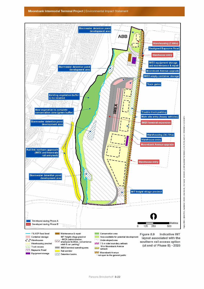
2025 8-21 Figure 8.9 Indicative IMT layout associated with the southern rail access option (at end of Phase B)
– 2025 8-22 Figure 8.10 Indicative IMT layout associated with the northern rail access option (at end of Phase C)
– 2030 8-25 Figure 8.11 Indicative IMT layout associated with the central rail access option (at end of Phase C) –
2030 8-26 Figure 8.12 Indicative IMT layout associated with the southern rail access option (at end of Phase C)
– 2030 8-27 Figure 8.13 Northern rail access option – Indicative construction footprint, access and haulage 8-31 Figure 8.14 Central rail access option – Indicative construction footprint, access and haulage 8-32 Figure 8.15 Southern rail access option – Indicative construction footprint, access and haulage 8-33
Parsons Brinckerhoff 8-1
8. Project development phasing and
construction
Chapter 8 provides a description of the key construction and operational activities required for the
Moorebank Intermodal Terminal (IMT) Project (the Project). The Project would involve the phased
delivery of import/export (IMEX) and interstate terminals and warehousing capacity in line with the
market demand for processing of containers through the IMT.
In order to assess the impacts of the Project, this Environmental Impact Statement (EIS) identifies a
series of phases of project development from site preparation through to the fully developed operation of
the Project (i.e. the Full Build). These phases are referred to as the ‘Project development phases’ and
are described throughout this chapter.
Details provided in this chapter are indicative only and provided for the purpose of environmental
assessment and planning approval. As explained in Chapter 1 – Introduction and Chapter 4 – Planning
and statutory requirements, the Moorebank Intermodal Company (MIC) is applying for Commonwealth
approval under the Commonwealth Environment Protection and Biodiversity Conservation Act 1999
(EPBC Act), and a Stage 1 State significant development (SSD) approval under the NSW Environmental
Planning and Assessment Act 1979 (EP&A Act). Therefore, the details provided in this EIS are at
concept level only. More information on the proposed approach to construction and operation would be
provided as part of the Stage 2 SSD approval process under the EP&A Act (refer to Chapter 4
Planning and statutory requirements). The exception is the Early Works development phase, for which
MIC is seeking consent to undertake preliminary works as part of the Stage 1 SSD development
approval, without the need for further consent. This chapter therefore also provides a full description of
the Early Works development phase (refer to section 8.3).
Chapter 7 – Project built form and operations provides a description of the layout and operation of the
Moorebank IMT at Full Build and should be read in conjunction with this chapter.
8.1 Precursors to the Moorebank IMT Project
There are a number of projects, either planned or underway, that will be undertaken before the
development of an IMT on the Project site. These are described below.
8.1.1 The Moorebank Units Relocation Project
The Project site is currently occupied by the School of Military Engineering (SME) and a range of other
minor Department of Defence (Defence) units. For construction of the Project to occur, the current SME
operations would need to be relocated, and any structures remaining within the future IMT footprint
relocated or demolished to make way for the IMT.
In September 2012, the Federal Parliamentary Standing Committee on Public Works approved the
Moorebank Units Relocation (MUR) Project to relocate 13 Defence units and four Defence facilities from
the Project site. The largest of these facilities is the SME, which will be rebuilt at the nearby Holsworthy
Barracks with training facilities, offices, facilities for explosive detection dogs, classrooms and
accommodation.
Parsons Brinckerhoff 8-2
The MUR Project will provide land for the development of the Moorebank IMT and is anticipated to be
completed by mid-2015. The MUR Project includes the removal and relocation to Holsworthy of some
existing items and buildings on the Project site which have been identified as having heritage value or
social significance to Defence. These include items from the Royal Australian Engineers (RAE) Heritage
Precinct and other memorials, including certain items of heritage significance, as detailed in
section 21.2 in Chapter 21 – European heritage and at http://www.defence.gov.au/id/moorebank/.
Depending on the outcome of opportunities to conserve other items of heritage significance, all
remaining structures and buildings on the site are to be removed and/or demolished as part of the site
rehabilitation works (refer section 8.1.2) and the Moorebank IMT Project (refer to section 8.3). Archival
recordings will be made of items of heritage significance that are not being relocated.
The MUR Project was subject to a separate environmental and planning approval process from that of the
Moorebank IMT Project. The impacts of the MUR Project (such as demolition or relocation of heritage items)
are not the subject of this EIS.
Further details of the MUR Project are available at http://www.defence.gov.au/id/moorebank/.
8.1.2 Site rehabilitation works
Following completion of the MUR Project, additional site rehabilitation works are required to reduce
environmental, health and safety risks on site before the start of IMT construction. Not all buildings and
structures on the Project site would be removed as part of the MUR Project; the remaining buildings
would need to be removed before construction of the IMT could begin. Furthermore, site preparation
activities such as decontamination of buildings with asbestos containing material, site stabilisation, and
establishment of construction areas and facilities, would also be necessary before IMT construction.
These activities are referred to as the 'site rehabilitation works'. These works are proposed to be
completed before development of the Project, as part of the Australian Government's obligations for
environmental stewardship of the land.
In March 2014, MIC provided a referral to the Commonwealth Minister for the Environment, which detailed
the activities related to site rehabilitation works (referral 2014/7152). The referral sought consent to
undertake these remediation and rehabilitation works before any future redevelopment of the site. The
action specified under referral 2014/7152 is as follows:
establishment of construction facilities and amenities on existing areas of hardstand, including staff
parking, site offices, hygiene units and kitchen facilities, plant laydown areas and wheel wash;
decontamination and demolition of eight buildings identified as including asbestos containing
material;
remediation of previously identified contamination hotspots, including underground storage tanks,
as identified in the Moorebank Intermodal Terminal Remediation Action Plan (RAP) (refer to
Volume 5A – Technical Paper 5 – Environmental Site Assessment (Phase 2) ) and shown in
Figure 15.1 in Chapter 15 – Contamination and soils;
decontamination and site stabilisation on the site of the plant and equipment operation training area
on the western side of the Project site, known as the ‘dust bowl’; and
construction of secure perimeter fencing.
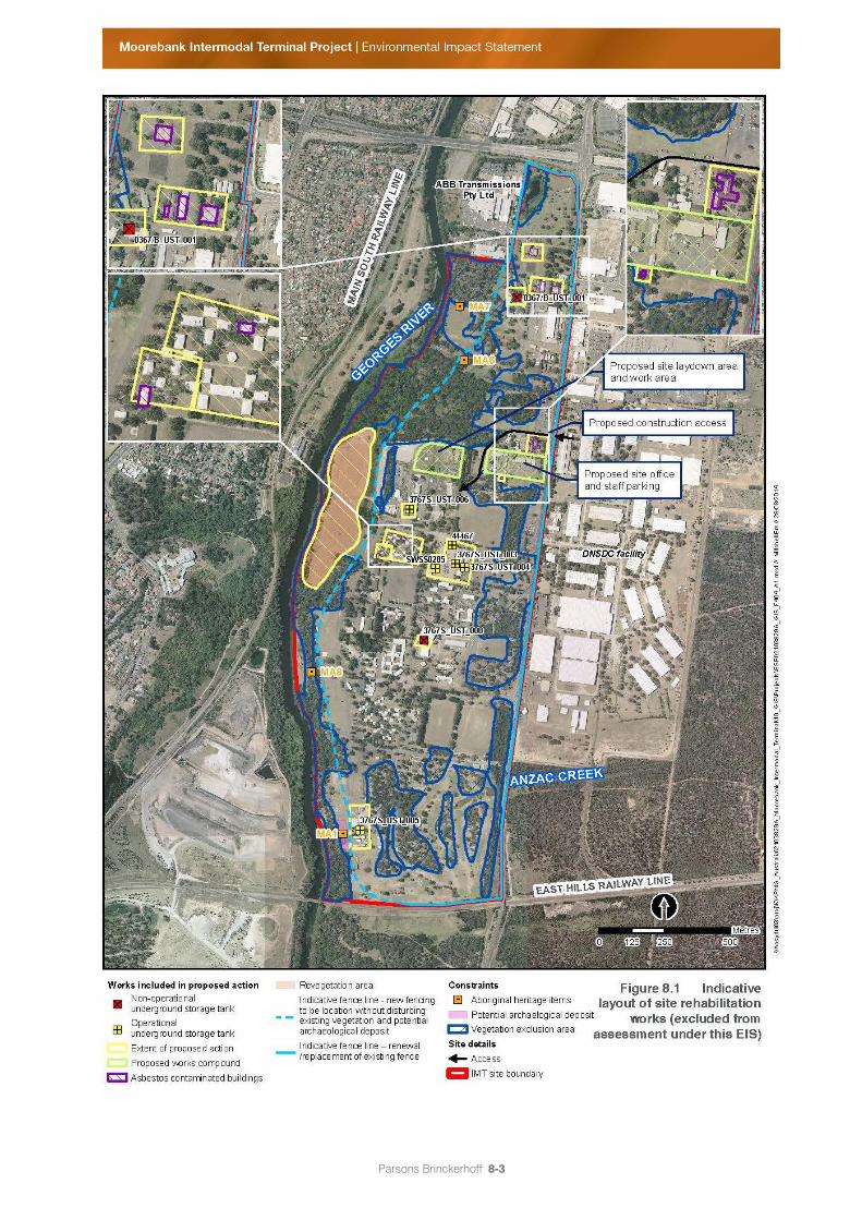
Figure 8.1 provides a plan of the indicative layout of the proposed site rehabilitation works under the
EPBC referral.
Parsons Brinckerhoff 8-3
Figure 8.1 Indicative layout of site rehabilitation works (excluded from assessment under this EIS)
Parsons Brinckerhoff 8-4
The site rehabilitation works are being undertaken to achieve environmental good practice by reducing
environmental and health and safety risks associated with the demobilisation of the Project site by
Defence.
On 9 May 2014 the proposed site rehabilitation works were declared (under delegation from the Minister
for the Environment) not to be a 'controlled action' and therefore not subject to further assessment under
the EPBC Act. This EIS therefore excludes consideration of the site rehabilitation works.
8.2 Phased Project development approach
As discussed in Chapter 1 – Introduction, the construction and operation of the Project would be
undertaken in a phased manner.
The rehabilitation works described in Section 8.1.2 (independent of the approval of the scope of this EIS)
would commence in early 2015.
Following completion of the rehabilitation works and assuming approval of the IMT Project that is the
subject of this EIS, the Early Works development phase would be undertaken. Development would then
progress with construction and later simultaneous operation activities until the Project reaches Full Build
in 2030. For the purposes of assessing the impacts of the Project, this EIS uses five development
phases to describe the likely construction and operational activities as the Project develops. It is
important to note that these development phases are indicative only, and would be confirmed by the
contractor selected for the future construction and operation of the Project.
The five Project development phases described in this EIS are:
1. Early Works (2015);
2. Phase A – construction of initial IMEX terminal and warehousing (20152018) (Phase A);
3. Phase B – operation of initial IMEX terminal and warehousing, construction of additional capacity
(2018–2025) (Phase B);
4. Phase C – operation of IMEX terminal and warehousing, construction of interstate terminal and
additional warehousing (2025–2030) (Phase C); and
5. Full Build – operation of IMEX terminal, warehousing and interstate terminal (2030).
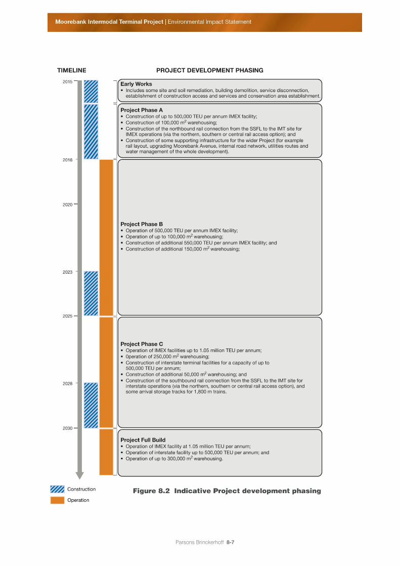
Figure 8.2 identifies the Project development phases, as well as the construction and operation program
and timing (also refer to section 8.2.1).
This chapter provides a description of the construction and operational activities likely to occur during
each Project development phase. In addition, as discussed in section 7.5 of Chapter 7 – Project built
form and operations, the proposal concept includes three proposed rail access options from the
Southern Sydney Freight Line (SSFL) (the northern, southern and central rail access options), with each
access option resulting in a different IMT layout. Therefore, this chapter also describes the IMT layout
associated with each of the rail access options. The final choice of rail access and IMT layout would be
determined during detailed design (following Stage 1 SSD approval).
Parsons Brinckerhoff 8-5
The Project development phasing provided in this chapter is indicative only. During detailed design, and
once the contractor for the development and operation of the Project has been selected, the Project
phasing would be confirmed. More precise details on each of the Project development phases would be
developed and provided as part of the Stage 2 SSD approval process. The exception is the Early Works
development phase, which MIC is seeking approval to commence as part of this Stage 1 SSD
development approval. Therefore, a more detailed description of this phase is provided in this EIS (refer
to section 8.3).
8.2.1 Project development timing
Construction of the Project is expected to begin in mid-2015, starting with the Early Works development
phase. The IMEX terminal, interstate terminal and the warehousing precinct would reach capacity in
2030. The IMEX terminal’s capacity at Full Build would be 1.05 million twenty-foot equivalent units (TEU)
a year in 2030 (i.e. 525,000 TEU a year inbound and 525,000 TEU outbound). The interstate terminal’s
capacity at Full Build would be 500,000 TEU a year in 2030 (i.e. 250,000 TEU a year inbound and
250,000 TEU outbound).
Warehousing associated with the IMEX facility would be developed progressively throughout the Project
development phases and would be located with efficient access to the IMEX terminal and Moorebank
Avenue.
In the longer term, and as the demand increases for interstate and regional freight movements by rail, an
interstate terminal would be developed on the IMT site. Interstate operations are expected to commence
in 2030.
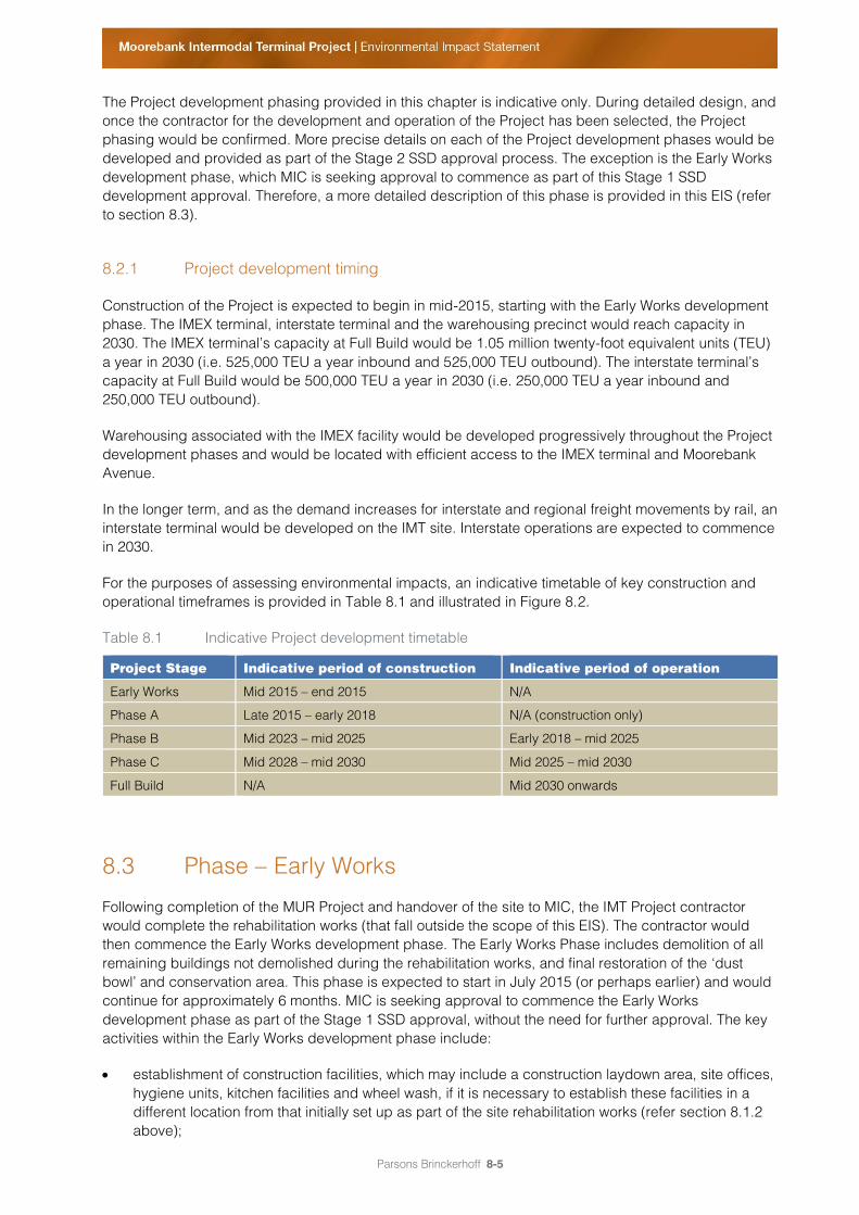
For the purposes of assessing environmental impacts, an indicative timetable of key construction and
operational timeframes is provided in Table 8.1 and illustrated in Figure 8.2.
Table 8.1 Indicative Project development timetable
Project Stage Indicative period of construction Indicative period of operation
Early Works Mid 2015 – end 2015 N/A
Phase A Late 2015 – early 2018 N/A (construction only)
Phase B Mid 2023 – mid 2025 Early 2018 – mid 2025
Phase C Mid 2028 – mid 2030 Mid 2025 – mid 2030
Full Build N/A Mid 2030 onwards
8.3 Phase Early Works
Following completion of the MUR Project and handover of the site to MIC, the IMT Project contractor
would complete the rehabilitation works (that fall outside the scope of this EIS). The contractor would
then commence the Early Works development phase. The Early Works Phase includes demolition of all
remaining buildings not demolished during the rehabilitation works, and final restoration of the ‘dust
bowl’ and conservation area. This phase is expected to start in July 2015 (or perhaps earlier) and would
continue for approximately 6 months. MIC is seeking approval to commence the Early Works
development phase as part of the Stage 1 SSD approval, without the need for further approval. The key
activities within the Early Works development phase include:
establishment of construction facilities, which may include a construction laydown area, site offices,
hygiene units, kitchen facilities and wheel wash, if it is necessary to establish these facilities in a
different location from that initially set up as part of the site rehabilitation works (refer section 8.1.2
above);
Parsons Brinckerhoff 8-6
demolition of existing buildings, structures and contaminated buildings not being removed as part
of the MUR Project or the site rehabilitation works (refer section 8.1.1 and 8.1.2 above);
some contaminated land remediation including removal of unexploded ordnance (UXO) and
explosive ordnance waste (EOW) if found, removal of asbestos contaminated buildings and
remediation of an area known to contain asbestos (as shown in Figure 8.3);
relocation of trees, including hollow bearing trees (i.e. those that provide ecologically important
roosting habitats);
service utility terminations and diversions;
establishment of the conservation area within the plant and equipment operation training area (known
as the 'dust bowl') including seed banking and planting; and
heritage impact mitigation works including archaeological salvage of Aboriginal and European
potential archaeological deposit (PAD) sites.
Further detail on the key activities within the Early Works development phase is provided below. Key
construction details such as earthworks, working hours, construction workforce, traffic and access, plant
and equipment and waste management are provided in section 8.8.
8.3.1 Building decontamination, demolition and removal
Buildings not removed as part of the MUR Project and site rehabilitation works (refer section 8.1.1 and
8.1.2 above) would need to be demolished during the Early Works development phase. Buildings to be
demolished include residential buildings (approx. 35,429 sq. m), a warehouse building
(approx. 29,650 sq. m) and office buildings (approx. 14,923 sq.
m).
The demolition works to be carried out include clearance of all structures, including retaining structures,
to ground level, and any other demolition required before construction of the Project can begin.
Demolition materials would, where appropriate, be stockpiled for reuse on the Project site during
construction, or lawfully disposed of at appropriate facilities. During this process Project contractors
would be required to comply with NSW and Commonwealth Work Health and Safety Regulations, and to
obtain relevant WorkCover insurance.
Buildings on the Project site that are known to be contaminated with asbestos would be removed as part
of the Early Works development phase. The methodology and process of removal of asbestos from
contaminated buildings is described in section 8.3.2 below.
A demolition plan including environmental management measures would be prepared before demolition
began. The plan would detail the methods and sequences for demolition. No explosives would be used
in demolition.
Parsons Brinckerhoff 8-7
Figure 8.2 Indicative Project development phasing
Parsons Brinckerhoff 8-8
8.3.2 Contaminated land investigation and remediation
Remediation of the Project site is necessary because the land has been used for Defence purposes
which may be associated with potential UXO, asbestos containing materials and hydrocarbons.
The Early Works development phase would involve the investigation and removal (if found) of UXO and
explosive ordnance waste (EOW). In addition, an area containing an asbestos-contaminated soil mound,
located in the south-eastern portion of the Project site adjacent to Jacquinot Court (referred to as
Area 18 and shown in Figure 8.3), would be remediated as part of the Early Works.
A preliminary RAP has been prepared for the Project and is included in Volume 5A – Technical Paper 5
– Environmental Site Assessment (Phase 2) of this EIS. The RAP identifies the processes and methods
that would be followed during the investigation and remediation of the contaminated material. In
addition, Section 10.1 of the RAP (Volume 5B) identifies remedial contingencies to effectively deal with
contaminated material that has not been previously identified. This includes a requirement to suspend
work to enable assessment of the suspected contamination and associated risks.
Section 15.5.1 of Chapter 15 – Contamination and soils summarises the soil and remediation methods
that may be utilised throughout Early Works and the following construction phases of the Project. These
methodologies include: containment and monitoring; consolidation and/or capping; excavation and
offsite disposal; and excavation and onsite treatment. Once further details of the Project are known, the
RAP would be updated and would confirm the remediation methodologies to be undertaken at the
Project site.
Unexploded ordnance and explosive ordnance waste removal
A review of the Defence National UXO database has found that the Project site is not in an area with
potential risk of UXO or EOW containing high explosive or other energetic material. Details of the review
are provided in Chapter 15 – Contamination and soils. However, prior to commencement of the Early
Works development phase, and in accordance with the requirements of the RAP, a UXO management
plan would be developed for the Project site. This plan would detail a framework for addressing the
discovery of UXO or EOW to ensure a safe environment for all project staff, visitors and contractors.
Decommissioning of underground/aboveground storage tanks
The removal of known underground storage tanks (USTs) (as per the NSW Protection of the Environment
Operations (POEO) (Underground Petroleum Storage Systems (UPSS)) Regulation 2008) would primarily
be undertaken as part of the site rehabilitation works (refer to section 8.1.2), and is not specifically
included within this EIS. Should any additional underground storage tanks (and associated
contamination) be identified during future excavation works, validation and removal would be
undertaken in accordance with the contingency measures prescribed in the RAP. One aboveground
storage tank (AST) has been identified on the Project site and would be removed as part of the Early
Works development phase, in accordance with the measures in the RAP.
Parsons Brinckerhoff 8-9
Removal of asbestos
Previous investigations have identified buildings containing asbestos at the Project site. Prior to the
demolition of any buildings onsite, testing would be undertaken to confirm the presence of asbestos
material. If confirmed, the demolition of the building and the removal of asbestos material would be
undertaken in accordance with the methodology provided in the RAP (and outlined below).
In addition, asbestos has been identified in an area (Area 18) adjacent to Jacquinot Court, as shown in
Figure 8.3. This area would be remediated as part of Early Works. The removal of asbestos would be
undertaken in accordance with the following methodology:
During the removal of the identified asbestos containing soil/materials, the following additional
processes would be implemented:
all asbestos removal, transport and disposal would be performed in accordance with the
Commonwealth Work Health and Safety Regulations 2011 (WHS Regulation);
the removal works would be conducted in accordance with the National Occupational Health
and Safety Commission Code of Practice for the Safe Removal of Asbestos, 2nd Edition;
as non-friable asbestos cement fragments are the key concern, a bonded asbestos removal
licence issued by WorkCover would be required for the removal of asbestos contaminated soil;
environmental management and work health and safety procedures would be put in place for
the asbestos removal during excavation, to protect the workers, surrounding residents and the
environment;
temporary stockpiles of asbestos containing materials would be covered to minimise dust and
potential asbestos release;
an asbestos removal clearance certificate would be prepared by an occupational hygienist
following the systematic removal of asbestos containing materials and any contaminated soils
from the site and validation of these areas (through visual inspection and laboratory analysis of
selected soil samples);
asbestos fibre air monitoring would be undertaken during the removal of the asbestos
materials and in conjunction with the visual clearance inspection. The monitoring would be
conducted in accordance with the National Occupational Health and Safety Commission's
Guidance Note on the Membrane Filter Method For Estimating Airborne Asbestos Fibre,
2nd Edition; and
validation of all excavations would be required including relevant monitoring and reporting.
Waste
Remediation of the Project site would produce waste materials for offsite disposal, including waste
classified as hazardous solid waste and general solid waste in accordance with the NSW Protection of
the Environment Operations (Waste) Regulation 2005 (see Chapter 15 – Contamination and soils). Other
less hazardous material may be classified as suitable for encapsulation on site and sealed under
pavements or hardstand areas. The methodology and processes for the disposal of waste are outlined
in Chapter 15 – Contamination and soils.
Parsons Brinckerhoff 8-10
8.3.3 Service utility terminations and diversions
The Project contractor would undertake a services search (both desktop and onsite investigations) to
verify the location and depth of services at the Project site. Services would be maintained, disconnected
or relocated as appropriate. The Project contractor would be required to arrange for suitability qualified
personnel to carry out the disconnections or relocations. These activities would involve obtaining the
relevant approvals from service authorities.
8.3.4 Establishment of the conservation area
The conservation area would be established along the western boundary of the Project site during the
Early Works development phase and would contribute to meeting the Project’s biodiversity offset
contributions. A management plan has been prepared for the Project (refer to Appendix E of the
Ecological Impact Assessment in Volume 4) which would guide the rehabilitation works for the
conservation area. Works would include eradication and suppression of weeds, followed by long-term
monitoring and low intensity maintenance to prevent re-emergence of weeds.
8.3.5 Establishment of construction facilities
The Project contractor would be responsible for establishing construction facilities and amenities on the
Project site. While the proposed location of construction facilities is not yet known, it is likely that this
would be located close to the vehicle access off Moorebank Avenue. Construction facilities would
include equipment storage, repair and maintenance facilities, contractors' office, staff parking, hygiene
units, kitchen facilities, plant laydown areas and wheel wash.
8.3.6 Heritage salvage works
As part of the Early Works development phase, Project contractors would undertake heritage mitigation
works including salvage of Aboriginal and European heritage sites. Prior to Early Works commencing,
background studies and subsurface testing would be undertaken to assist in defining and scoping the
heritage salvage works. This includes:
consultation with the NSW Office of Environment and Heritage (OEH) and Registered Aboriginal
Parties;
scarred tree assessment including consultation with Registered Aboriginal Parties and field
investigation;
archival recording of affected European heritage sites and salient aspects of the broader
Moorebank cultural landscape; and
subsurface testing of MRSA2 and MA10 (refer to Figure 20.3 in Chapter 20 – Aboriginal heritage,
which shows the location of these artefacts and archaeological deposits).
Parsons Brinckerhoff 8-11
A methodology for the surface salvage of European and Aboriginal heritage sites would be prepared,
and the methodology for the salvage of Aboriginal heritage sites provided to Registered Aboriginal
Parties for review. During this time an Aboriginal Cultural Heritage Assessment Report (ACHAR) would
be prepared and approval from OEH to excavate the heritage sites would be sought. The methodology
prepared during this process would then be used during the Early Works salvage works, which include:
salvage of Aboriginal objects (MA1, MA2, MA3, MA4, MRSA2 and MA10) and the subsurface
salvage of MA5 and MA9;
surface salvage of European sites MHPAD1 and MHPAD2;
salvage of other Aboriginal and European heritage sites identified through the background studies
and subsurface testing preceding Early Works (as described above); and
relocation of scarred trees, where required.
Chapter 20 – Aboriginal heritage and Chapter 21 – European heritage provide further detail on these
objects and sites, including the location of these heritage items.
In addition, the Cullen Universal Steel Truss (CUST) Hut, the STRARCH hangar and the Transport
Compound Workshop (referred to as building 99), currently located on the SME site, were identified
during the MUR Project as potentially meeting the threshold for nomination to the Commonwealth
Heritage List, but have not been identified for relocation as part of the MUR Project. A condition survey
would be undertaken to assess the condition of these buildings and to determine the requirement for
relocation off site. Options to reuse in situ would also be considered if necessary. Alternatively, if
considered appropriate, these buildings would be demolished.
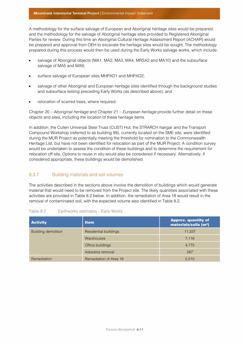
8.3.7 Building materials and soil volumes
The activities described in the sections above involve the demolition of buildings which would generate
material that would need to be removed from the Project site. The likely quantities associated with these
activities are provided in Table 8.2 below. In addition, the remediation of Area 18 would result in the
removal of contaminated soil, with the expected volume also identified in Table 8.2.
Table 8.2 Earthworks estimates – Early Works
Activity Item Approx. quantity of
materials/soils (m³)
Building demolition Residential buildings 11,337
Warehouses 7,116
Office buildings 4,775
Asbestos removal 287
Remediation Remediation of Area 18 5,510
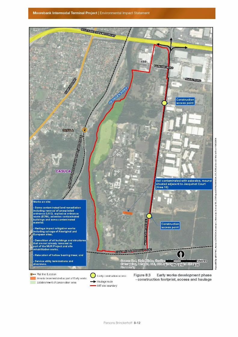
Parsons Brinckerhoff 8-12
Figure 8.3 Early works development phase – construction footprint, access and haulage
Parsons Brinckerhoff 8-13
8.4 Phase A – Construction of initial IMEX terminal and
warehousing (2015–2018)
8.4.1 Construction activities
The greatest level of construction activity would likely occur during the early phase of the Project, during
Phase A. This phase involves earthworks, construction of the initial IMEX terminal and warehousing
facilities, construction of the rail connection from the SSFL to the IMT site and some supporting
infrastructure for the wider Project.
Construction of the initial IMEX freight terminal facilities for a capacity of 500,000 TEU a year and
100,000 sq. m of warehousing is likely to commence in the third quarter of 2015. During this time,
ancillary facilities including IMEX administration, the plant and equipment maintenance and repair
building, and the main Moorebank IMT gate would also be developed.
The Project involves the construction of a rail access from the SSFL to the IMT site. This access would
be gained via one of the rail access options (northern, central or southern) outlined in detail in
section 7.5 of Chapter 7 – Project built form and operations. The rail access has been designed to be
built in two stages. In Phase A, the bridge across the Georges River and the rail connection from the
IMEX terminal (referred to as the northbound rail connection) to the SSFL would be constructed. This
would facilitate train movements to and from Port Botany for the IMEX facility.
The proposed northern and southern rail access options both have only one bridge structure, which
would allow for both IMEX and interstate train entry and exit to the SSFL. In the case of the northern rail
access option, there is a turnout from the bridge structure on the western bank of the Georges River
(refer to Figure 7.4 in Chapter 7 – Project built form and operations). To avoid the need for bridge works
in subsequent Project development phases, both the northern and the southern rail access options
would include a bridge structure over the Georges River that could accommodate both IMEX and
interstate train entry and exit. For the northern rail access option, the turnout structure for interstate train
entry to and exit from the SSFL would also be constructed during Phase A. Details of the construction
footprint and proposed construction approach for each of the northern and southern rail access options
are provided in section 8.8.
The central rail access option would require two separate bridge structures one for the northbound rail
connection and one for the southbound rail connection. Only the northbound rail connection would be
constructed as part of Phase A.
All utilities, including power, gas, water, sewer and stormwater trunks, would ideally be installed during
Phase A. These utilities would be capable of supplying both the IMEX and the warehousing precinct at
their full capacity; however, during Phase A only connections to the IMEX and the initial warehousing
(100,000 sq. m) would be made. Stub connections would be provided for future extensions to additional
IMEX and warehousing and the interstate terminal, while avoiding future road openings. Internal roads
would be developed as part of Phase A to suit initial IMEX and warehouse operations, while allowing for
expansion in subsequent stages.
Table 8.3 identifies the key construction elements likely to occur during Phase A. These details are
indicative only and would be subject to confirmation during the next stage of approval under the NSW
EP&A Act (i.e. Stage 2 SSD approval). Construction would take approximately two years, followed by the
start of operation of the initial IMEX terminal facilities and warehousing in 2018.
The construction footprint, access and haulage details for Phase A are described in section 8.8 and
illustrated in Figures 8.13 to 8.15.
Parsons Brinckerhoff 8-14
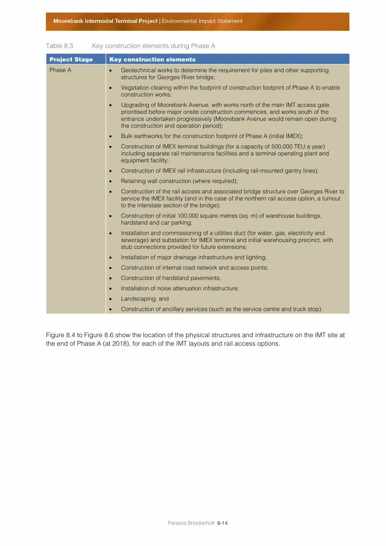
Table 8.3 Key construction elements during Phase A
Project Stage Key construction elements
Phase A Geotechnical works to determine the requirement for piles and other supporting
structures for Georges River bridge;
Vegetation clearing within the footprint of construction footprint of Phase A to enable
construction works;
Upgrading of Moorebank Avenue, with works north of the main IMT access gate
prioritised before major onsite construction commences, and works south of the
entrance undertaken progressively (Moorebank Avenue would remain open during
the construction and operation period);
Bulk earthworks for the construction footprint of Phase A (initial IMEX);
Construction of IMEX terminal buildings (for a capacity of 500,000 TEU a year)
including separate rail maintenance facilities and a terminal operating plant and
equipment facility;
Construction of IMEX rail infrastructure (including rail-mounted gantry lines);
Retaining wall construction (where required);
Construction of the rail access and associated bridge structure over Georges River to
service the IMEX facility (and in the case of the northern rail access option, a turnout
to the interstate section of the bridge);
Construction of initial 100,000 square metres (sq. m) of warehouse buildings,
hardstand and car parking;
Installation and commissioning of a utilities duct (for water, gas, electricity and
sewerage) and substation for IMEX terminal and initial warehousing precinct, with
stub connections provided for future extensions;
Installation of major drainage infrastructure and lighting;
Construction of internal road network and access points;
Construction of hardstand pavements;
Installation of noise attenuation infrastructure;
Landscaping; and
Construction of ancillary services (such as the service centre and truck stop).
Figure 8.4 to Figure 8.6 show the location of the physical structures and infrastructure on the IMT site at
the end of Phase A (at 2018), for each of the IMT layouts and rail access options.
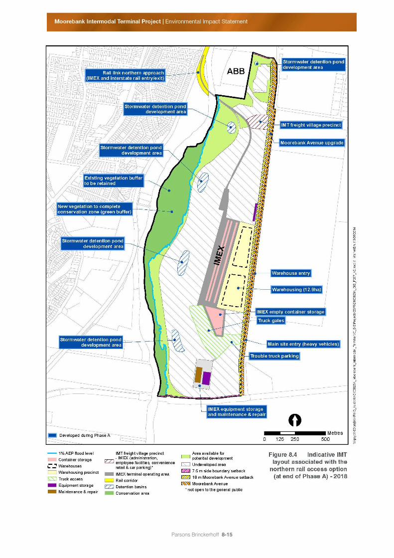
Parsons Brinckerhoff 8-15
Figure 8.4 Indicative IMT layout associated with the northern rail access option (at end of Phase A)
– 2018
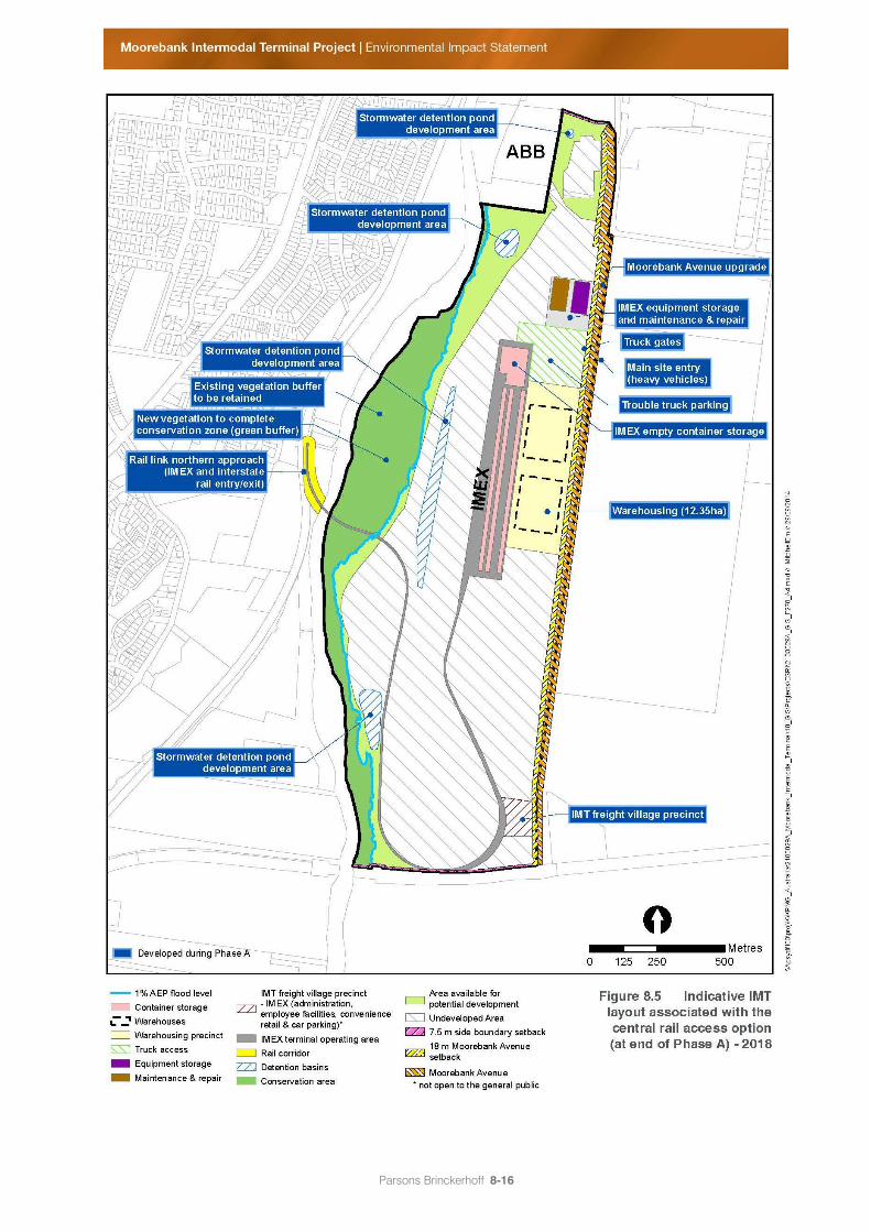
Parsons Brinckerhoff 8-16
Figure 8.5 Indicative IMT layout associated with the central rail access option (at end of Phase A) –
2018
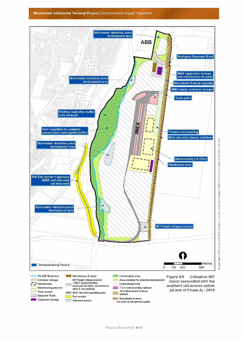
Parsons Brinckerhoff 8-17
Figure 8.6 Indicative IMT layout associated with the southern rail access option (at end of Phase A)
– 2018
Parsons Brinckerhoff 8-18
8.5 Phase B – Operation of initial IMEX terminal and
warehousing, construction of additional IMEX and
warehousing capacity (2018–2025)
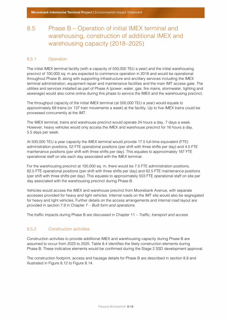
8.5.1 Operation
The initial IMEX terminal facility (with a capacity of 500,000 TEU a year) and the initial warehousing
precinct of 100,000 sq. m are expected to commence operation in 2018 and would be operational
throughout Phase B, along with supporting infrastructure and ancillary services including the IMEX
terminal administration, equipment repair and maintenance facilities and the main IMT access gate. The
utilities and services installed as part of Phase A (power, water, gas, fire mains, stormwater, lighting and
sewerage) would also come online during this phase to service the IMEX and the warehousing precinct.
The throughput capacity of the initial IMEX terminal (at 500,000 TEU a year) would equate to
approximately 69 trains (or 137 train movements a week) at the facility. Up to five IMEX trains could be
processed concurrently at the IMT.
The IMEX terminal, trains and warehouse precinct would operate 24 hours a day, 7 days a week.
However, heavy vehicles would only access the IMEX and warehouse precinct for 16 hours a day,
5.5 days per week.
At 500,000 TEU a year capacity the IMEX terminal would provide 17.5 full-time equivalent (FTE)
administration positions, 52 FTE operational positions (per shift with three shifts per day) and 4.5 FTE
maintenance positions (per shift with three shifts per day). This equates to approximately 187 FTE
operational staff on site each day associated with the IMEX terminal.
For the warehousing precinct at 100,000 sq. m, there would be 7.5 FTE administration positions,
82.5 FTE operational positions (per shift with three shifts per day) and 82.5 FTE maintenance positions
(per shift with three shifts per day). This equates to approximately 503 FTE operational staff on site per
day associated with the warehousing precinct during Phase B.
Vehicles would access the IMEX and warehouse precinct from Moorebank Avenue, with separate
accesses provided for heavy and light vehicles. Internal roads on the IMT site would also be segregated
for heavy and light vehicles. Further details on the access arrangements and internal road layout are
provided in section 7.9 in Chapter 7 – Built form and operations.
The traffic impacts during Phase B are discussed in Chapter 11 – Traffic, transport and access.
8.5.2 Construction activities
Construction activities to provide additional IMEX and warehousing capacity during Phase B are
assumed to occur from 2023 to 2025. Table 8.4 identifies the likely construction elements during
Phase B. These indicative elements would be confirmed during the Stage 2 SSD development approval.
The construction footprint, access and haulage details for Phase B are described in section 8.8 and
illustrated in Figure 8.12 to Figure 8.14.
Parsons Brinckerhoff 8-19
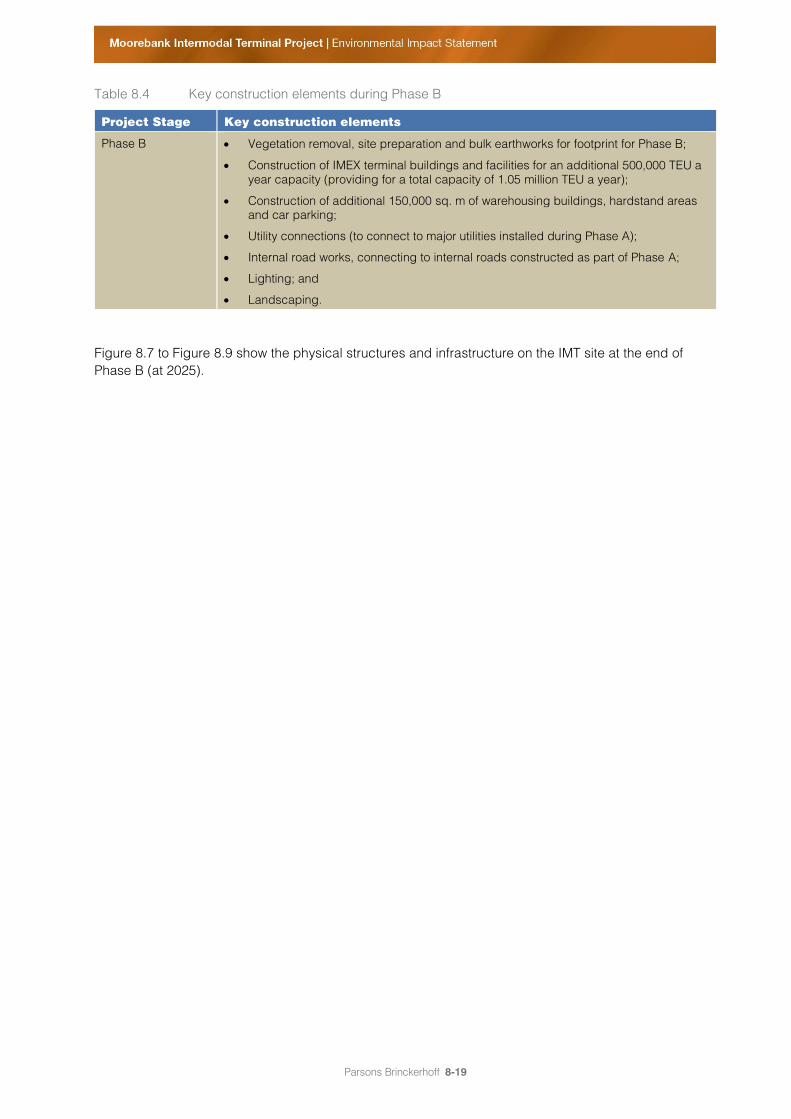
Table 8.4 Key construction elements during Phase B
Project Stage Key construction elements
Phase B Vegetation removal, site preparation and bulk earthworks for footprint for Phase B;
Construction of IMEX terminal buildings and facilities for an additional 500,000 TEU a
year capacity (providing for a total capacity of 1.05 million TEU a year);
Construction of additional 150,000 sq. m of warehousing buildings, hardstand areas
and car parking;
Utility connections (to connect to major utilities installed during Phase A);
Internal road works, connecting to internal roads constructed as part of Phase A;
Lighting; and
Landscaping.
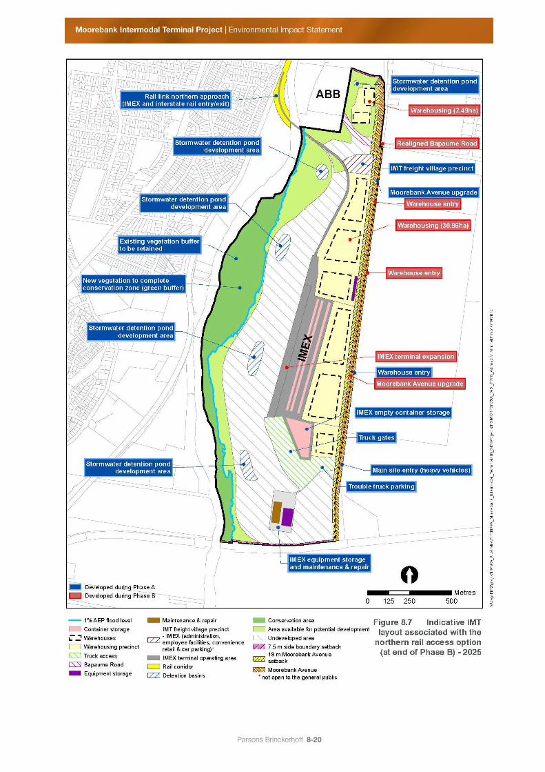
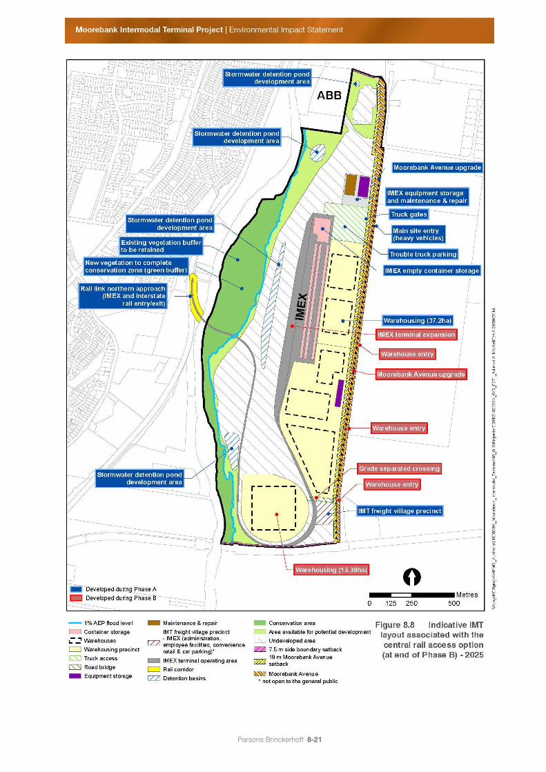
Figure 8.7 to Figure 8.9 show the physical structures and infrastructure on the IMT site at the end of
Phase B (at 2025).
Parsons Brinckerhoff 8-20
Figure 8.7 Indicative IMT layout associated with the northern rail access option (at end of Phase B)
– 2025
Parsons Brinckerhoff 8-21
Figure 8.8 Indicative IMT layout associated with the central rail access option (at end of Phase B) –
2025
Parsons Brinckerhoff 8-22
Figure 8.9 Indicative IMT layout associated with the southern rail access option (at end of Phase B)
– 2025
Parsons Brinckerhoff 8-23
8.6 Phase C – Operation of IMEX terminal and warehousing,
construction of interstate terminal and additional
warehousing (2025–2030)
8.6.1 Operation
By 2025 it is likely that the IMEX terminal would be operating at full capacity and there would be
approximately 250,000 sq. m of warehousing. The IMEX terminal would provide for approximately
137 trains (273 train movements per week) at the facility. Between 2025 and 2030 the IMEX terminal and
trains would operate 24 hours a day, 7 days a week. The IMEX truck gates and heavy vehicles
accessing the warehousing precinct would operate for 16 hours a day, 5.5 days per week.
During Phase C the IMEX terminal would provide 35 FTE administration positions, 104 FTE operational
positions (per shift with three shifts per day) and 9 FTE maintenance positions (per shift with three shifts
per day). This equates to approximately 374 FTE operational staff on site per day associated with the
IMEX terminal.
The warehousing precinct would provide 18.5 FTE administration positions, 206.5 FTE operational
positions (per shift with three shifts per day) and 206.5 FTE maintenance positions (per shift with three
shifts per day). This equates to approximately 1,258 FTE operational staff on site per day associated
with the warehousing precinct.
Details of IMEX throughput capacity, arrivals and departures, and container handling and storage are
provided in Chapter 7 – Project built form and operations.
The traffic impacts during Phase C are discussed in Chapter 11 – Traffic, transport and access.
8.6.2 Construction activities
Phase C includes construction of the interstate terminal and associated works for a maximum capacity
of 500,000 TEU a year, as well as construction of an additional 50,000 sq. m of warehousing.
Construction works are assumed to occur between 2028 and 2030. Table 8.5 identifies the likely key
construction elements during Phase C. These are indicative only and would be subject to the next stage
of approval (i.e. Stage 2 SSD development approval).
The construction footprint, access and haulage details for Phase C are described in section 8.8 and
illustrated in Figure 8.13 to Figure 8.15.
Parsons Brinckerhoff 8-24
Table 8.5 Key construction elements during Phase C
Project Stage Key construction elements
Phase C Vegetation clearing within the construction footprint for Phase C;
Site preparation, including bulk earthworks and remediation of Phase C area;
Geotechnical works for the development of the interstate terminal area;
Construction of the southbound rail connection for service the interstate terminal (in
the case of the central rail access option, this involves the construction of a new
bridge structure over Georges River);
Utility connections and additional minor drainage works to connection to major utilities
and drainage installed during Phase A and Phase B;
Construction of rail infrastructure for interstate terminal, including rail-mounted gantry
lines;
Construction of interstate terminal buildings and associated facilities including
maintenance facility, administration, car parking and fuel storage;
Construction of additional 50,000 sq. m of warehousing buildings, hardstand areas
and car parking;
Construction of internal roads;
Construction of pavements;
Construction of retaining walls;
Installation of noise attenuation infrastructure;
Landscaping; and
Lighting.
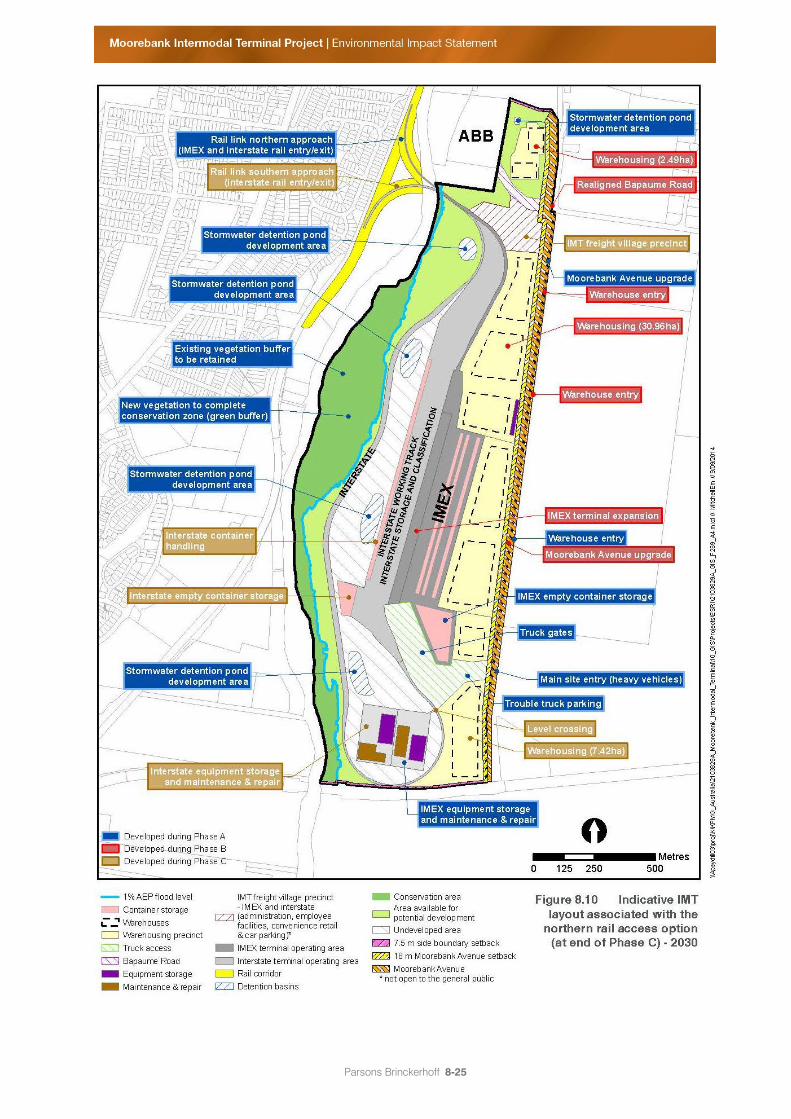
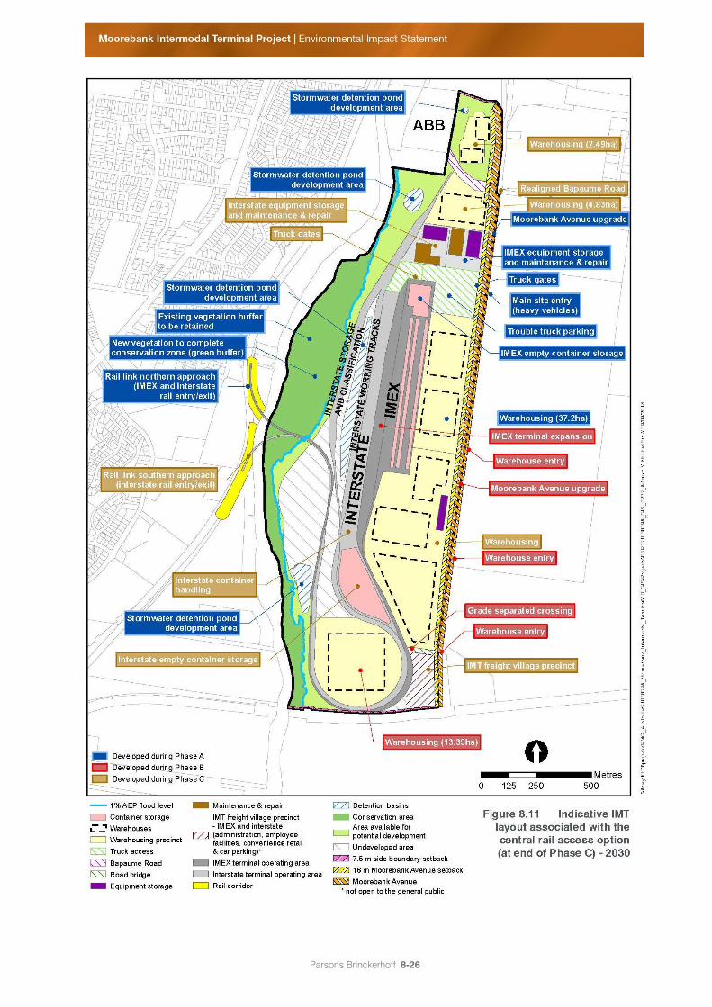
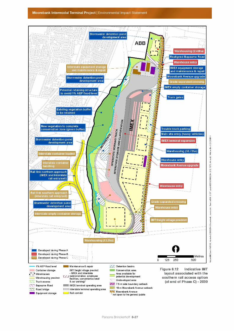
Figure 8.10 to Figure 8.12 show the physical structures and infrastructure on the IMT site at the end of
Phase C (at 2030), for each of the three IMT layouts.
Parsons Brinckerhoff 8-25
Figure 8.10 Indicative IMT layout associated with the northern rail access option (at end of Phase C)
– 2030
Parsons Brinckerhoff 8-26
Figure 8.11 Indicative IMT layout associated with the central rail access option (at end of Phase C) –
2030
Parsons Brinckerhoff 8-27
Figure 8.12 Indicative IMT layout associated with the southern rail access option (at end of Phase C)
– 2030
Parsons Brinckerhoff 8-28
8.7 Full Build – Operation of IMEX terminal, warehousing and
interstate terminal (2030 onwards)
8.7.1 Operation
By 2030 it is expected that the Moorebank IMT would reach capacity, and as such the Full Build
scenario is intended to represent the developed terminal as it would operate on an ongoing basis. There
would therefore be no further construction activity on the Project site. Full Build would include the IMEX
terminal operating at 1.05 million TEU a year, 300,000 sq. m of warehousing and 500,000 TEU a year of
interstate capacity. Detailed information on the operation of the IMEX and warehousing precinct at Full
Build, including throughput capacity, arrivals and departures, container handling and storage and
vehicle access is provided in Chapter 7 – Project built form and operations.
The IMEX facility at Full Build would accommodate approximately 137 trains (or 273 train movements) a
week. This would equate to approximately 525,000 TEU inbound and 525,000 TEU outbound a year. The
IMEX facility provide for 35 administrative staff, as well as 104 operational and 9 maintenance staff per
shift (with three shifts per day). This equals a total of approximately 374 onsite operational staff.
The interstate terminal operating at Full Build (up to 500,000 TEU a year) would equate to approximately
12 interstate trains (or 24 train movements) a week. Depending on timing of demand for interstate
freight, up to four interstate trains could be processed concurrently on site.
At Full Build the interstate terminal would provide 35 FTE administration positions, 78 FTE operational
positions (per shift with three shifts per day) and 7 FTE maintenance positions (per shift with three shifts
per day) on site. This equates to approximately 290 FTE operational staff on site per day associated with
the interstate terminal.
At Full Build the warehousing precinct would accommodate 22 FTE administration positions, 248 FTE
operational positions (per shift with three shifts per day) and 248 FTE maintenance positions (per shift
with three shifts per day). This equates to approximately1,509 FTE operational staff on site per day
associated with the warehousing precinct.
Details of the throughput capacity and staff numbers for the IMEX facility are provided in section 8.6.1.
The IMEX and interstate terminal and trains would operate 24 hours a day, 7 days a week. Heavy
vehicles would also access the warehouse precinct 24 hours a day, 7 days a week.
The Full Build project development represents the proposal for which MIC is seeking approval under the
Stage 1 SSD approval. Figure 7.4 to Figure 4.6 in Chapter 7 – Project built form and operations show the
Full Build of the Project.
8.8 Key construction details
8.8.1 Project construction footprint
The construction footprint represents the area within which construction activities would occur. For the
purposes of assessment, the construction footprint for each development phase has been assumed to
be entirely cleared of vegetation, ready for the construction of buildings, hard surfaces and
infrastructure.
Parsons Brinckerhoff 8-29
Construction of the Project would occur progressively through defined phases, as outlined in the
previous sections of this chapter. This approach avoids the need to remove vegetation and expose
areas of the Project site long before development begins. The construction footprint during each Project
development phase, for each of the three IMT layouts and associated rail access options, is shown in
Figure 8.13 to Figure 8.15. The construction footprint for the Early Works development phase has been
provided separately in Figure 8.3.
Construction related activities (including stockpiles and equipment storage compounds) would be
contained within the construction footprint (refer also to section 8.8.3). The construction footprint
includes:
the entire Project site for the development of the IMT, except for:
most of the conservation zone;
some additional areas within which vegetation would be retained (as shown in Figure 8.13 to
Figure 8.15);
a section of the Georges River (including the river and the river banks) for construction of the rail
bridge and for construction access (note that this varies between the three rail access options, as
shown in Figure 8.13 to Figure 8.15 and further described in section 8.8.2 below);
areas to accommodate drainage channels across the conservation area between the IMT and the
Georges River;
Moorebank Avenue for the upgrade to four lanes; and
Bapaume Road for reconstruction works.
Construction related activities would generally be confined to the construction/development footprint.
Construction activities that could occur outside the construction footprint include:
establishment of the conservation zone, which would occur during the Early Works development
phase; and
landscaping.
8.8.2 Rail access construction footprint
In relation to rail access from the SSFL to the IMT site, the construction footprint extends into land on the
western bank of the Georges River for all three rail access options. The extent of the construction
footprint is as follows:
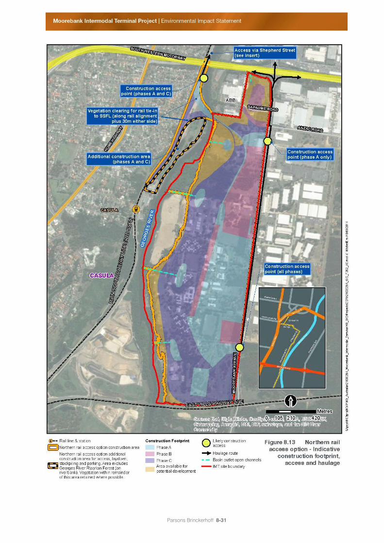
Under the northern rail access option, the construction footprint includes land currently owned by
Liverpool City Council (LCC), known as the ‘Northern Powerhouse Land’. A corridor approximately
60 m wide (30 m either side of the rail corridor) would be provided for the construction of the rail link
under this option. In addition, it is likely that the Project contractors would occupy an area of land
directly south of the rail link, on the Northern Powerhouse Land, for the purposes of operation and
storage of machinery and equipment. This is shown in Figure 8.13. The construction footprint also
extends into Sydney Trains (formerly RailCorp) and NSW Roads and Maritime Services (RMS) land
to tie-in to the existing SSFL.
Parsons Brinckerhoff 8-30
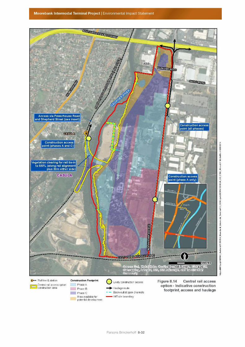
Under the central rail access option, the construction footprint extends on to Commonwealth land
on the western bank of the Georges River and a 60 m wide corridor has been provided for
construction, as shown in Figure 8.14. The construction footprint also extends into the Glenfield
Landfill site (Lot 103 DP 1143827) as well as LCC land (Lot 1 DP 1115187, Lot 22 DP 1132574 and
Lot 24 DP 1132574) and a number of Sydney Trains lots, for the purposes of rail tie-in.
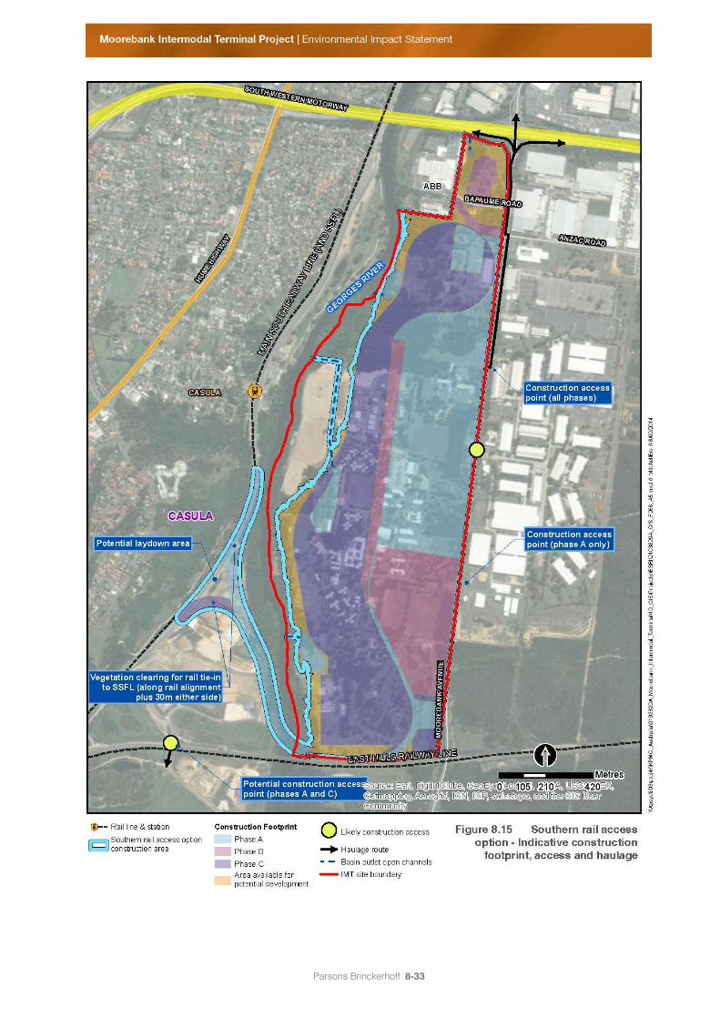
Under the southern rail access option, the construction footprint extends into land within the
Glenfield Landfill site (owned by Glenfield Waste Services). A 60 m wide corridor has been
provided, as shown in Figure 8.15. Construction works would also extend into Commonwealth land
(Lot 4 DP 1130937) (the 'hourglass land') and also Sydney Trains land for tie-in to the SSFL.
Contractors are likely to occupy land on the Glenfield Landfill site within the area referred to as the
‘potential laydown area’, shown in Figure 8.15.
In terms of the construction methodology, all three rail access options would require access for labour,
plant and materials predominantly from the IMT site on the eastern bank of the Georges River. However,
some construction would also be undertaken on the western bank including the tie-ins to the existing
SSFL.
For the northern rail access option, it is anticipated that approximately 60% of the rail bridge and
approach viaduct structures (including the piles, piers and deck) would be constructed from the eastern
bank (from the IMT site), while the remaining 40% would be constructed from the western bank. Based
on the indicative plans it is expected that construction for the northern rail access option would take
approximately 18 months; however, this timing would be confirmed during Stage 2 SSD.
For the central rail access option, it is anticipated that approximately 75% of the rail bridge and
approach viaduct structures would utilise access from the eastern bank (IMT site) and 25% from the
western bank, on the 'hourglass' land (shown in Figure 2.3). This construction estimate is indicative only
and would be subject to further refinements during the detailed design phase and Stage 2 SSD approval
process.
For the southern rail access option, it is anticipated that approximately 90% of the rail bridge and
approach viaduct structures would utilise access from the eastern bank (IMT site) and 10% from the
western bank, on the Glenfield Landfill site. Again, this would be subject to detailed design and further
refinement during the Stage 2 SSD approvals.
For both the central and the southern rail access options, the construction period is estimated at
24 months, based on the indicative site layouts. Again, the timing would be confirmed during Stage 2
SSD.
In addition, both the northern and the central rail access options would require the partial realignment of
Powerhouse Road, to provide for the tie-in of the rail link to the SSFL. However, it is not likely that an
extended closure of Powerhouse Road would be required.
Parsons Brinckerhoff 8-31
Figure 8.13 Northern rail access option – Indicative construction footprint, access and haulage
Parsons Brinckerhoff 8-32
Figure 8.14 Central rail access option – Indicative construction footprint, access and haulage
Parsons Brinckerhoff 8-33
Figure 8.15 Southern rail access option – Indicative construction footprint, access and haulage
Parsons Brinckerhoff 8-34
8.8.3 Earthworks
The existing Project site has a very flat gradient (0.1%) from north to south and is tiered from west to east
between the main portion of the Project site and the area adjacent to the Georges River.
The indicative design has sought to establish a level across the Project site and a minimal
northsouth gradient that is suitable for the efficient operation of rail infrastructure and rail-mounted
gantries, which have specific requirements related to changes in surface level.
The indicative design has also focused on optimising a cut and fill balance across the IMT site to
minimise the requirement for fill to be imported or excess spoil to be exported. The design has also
attempted to minimise elevation of the Project site from its current natural surface level as much as
practicable, in order to minimise costs and visual impacts and also to avoiding flooding of surrounding
areas. There would be no change to the levels or elevation of the proposed conservation area.
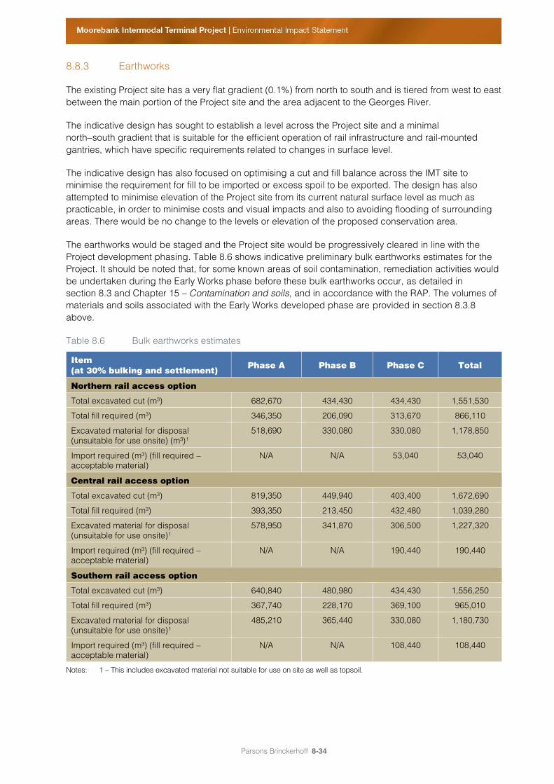
The earthworks would be staged and the Project site would be progressively cleared in line with the
Project development phasing. Table 8.6 shows indicative preliminary bulk earthworks estimates for the
Project. It should be noted that, for some known areas of soil contamination, remediation activities would
be undertaken during the Early Works phase before these bulk earthworks occur, as detailed in
section 8.3 and Chapter 15 – Contamination and soils, and in accordance with the RAP. The volumes of
materials and soils associated with the Early Works developed phase are provided in section 8.3.8
above.
Table 8.6 Bulk earthworks estimates
Item
(at 30% bulking and settlement) Phase A Phase B Phase C Total
Northern rail access option
Total excavated cut (m³) 682,670 434,430 434,430 1,551,530
Total fill required (m³) 346,350 206,090 313,670 866,110
Excavated material for disposal
(unsuitable for use onsite) (m³)¹
518,690 330,080 330,080 1,178,850
Import required (m³) (fill required –
acceptable material)
N/A N/A 53,040 53,040
Central rail access option
Total excavated cut (m³) 819,350 449,940 403,400 1,672,690
Total fill required (m³) 393,350 213,450 432,480 1,039,280
Excavated material for disposal
(unsuitable for use onsite)¹
578,950 341,870 306,500 1,227,320
Import required (m³) (fill required –
acceptable material)
N/A N/A 190,440 190,440
Southern rail access option
Total excavated cut (m³) 640,840 480,980 434,430 1,556,250
Total fill required (m³) 367,740 228,170 369,100 965,010
Excavated material for disposal
(unsuitable for use onsite)¹
485,210 365,440 330,080 1,180,730
Import required (m³) (fill required –
acceptable material)
N/A N/A 108,440 108,440
Notes: 1 – This includes excavated material not suitable for use on site as well as topsoil.
Parsons Brinckerhoff 8-35
8.8.4 Compounds, storage and stockpile areas
The Project contractor would use construction compounds on the Project site to undertake various
preparatory activities and to store materials for use in finished structures. Some of the principal activities
that would occur in the construction compounds include:
office and administrative functions;
parking for staff and construction vehicles;
staff facilities;
workshops and maintenance areas; and
material and equipment storage and stockpiles.
The location and number of construction compounds would be determined by the Project contractor. In
addition, construction compounds are likely to be required on the western side of the Georges River for
construction of the selected rail access option. The likely locations of the construction compounds under
each of the rail access options are discussed in section 8.8.2 above.
Several additional temporary stockpile sites would be required for the Project to store, prepare and
distribute materials. Construction compounds and stockpiles would be located within the confines of the
construction footprint (refer to Figure 8.13 to Figure 8.15) in areas that meet the following environmental
criteria:
located more than 40 m from waterways, where practicable;
located in areas of low ecological and heritage conservation value;
no significant clearing of native vegetation beyond that already required for the Project;
minimise impacts on amenity of the closest sensitive receiver; and
located on relatively level ground.
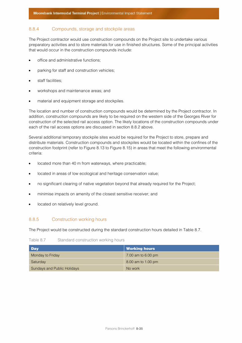
8.8.5 Construction working hours
The Project would be constructed during the standard construction hours detailed in Table 8.7.
Table 8.7 Standard construction working hours
Day Working hours
Monday to Friday 7.00 am to 6.00 pm
Saturday 8.00 am to 1.00 pm
Sundays and Public Holidays No work
Parsons Brinckerhoff 8-36
Some construction activities may be required to occur outside these hours, to minimise potential impacts
on the surrounding community. Generally, works undertaken on public infrastructure, such as roads, rail,
water, electricity, gas, sewage or drainage, need to be undertaken outside standard construction hours
to maintain the operational integrity of the infrastructure. Potentially affected residents and relevant
authorities would be notified in advance of the works intended to be performed outside standard hours.
Exemptions and approval for works outside standard hours may be required during the following
circumstances:
when works are required by utility service providers or where impacts on services cannot be
reasonably managed within standard hours;
where works require track possessions for the tie-in to the SSFL (that is, temporary rail line
closures); and
when making and unloading oversize deliveries using machinery that can only travel between
certain hours (as specified by the NSW Police or RMS).
As recommended in Chapter 12 – Noise and vibration, other exemptions (subject to approval) may
include works that are not audible at the nearest receivers or works required to maintain health and
safety, avoid loss of life or injury and/or to prevent environmental damage.
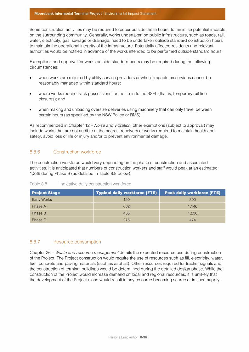
8.8.6 Construction workforce
The construction workforce would vary depending on the phase of construction and associated
activities. It is anticipated that numbers of construction workers and staff would peak at an estimated
1,236 during Phase B (as detailed in Table 8.8 below).
Table 8.8 Indicative daily construction workforce
Project Stage Typical daily workforce (FTE) Peak daily workforce (FTE)
Early Works 150 300
Phase A 662 1,146
Phase B 435 1,236
Phase C 275 474
8.8.7 Resource consumption
Chapter 26 – Waste and resource management details the expected resource use during construction
of the Project. The Project construction would require the use of resources such as fill, electricity, water,
fuel, concrete and paving materials (such as asphalt). Other resources required for tracks, signals and
the construction of terminal buildings would be determined during the detailed design phase. While the
construction of the Project would increase demand on local and regional resources, it is unlikely that
the development of the Project alone would result in any resource becoming scarce or in short supply.
Parsons Brinckerhoff 8-37
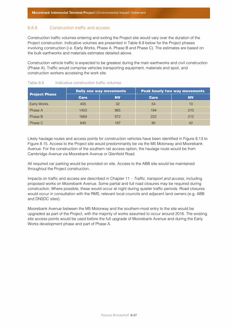
8.8.8 Construction traffic and access
Construction traffic volumes entering and exiting the Project site would vary over the duration of the
Project construction. Indicative volumes are presented in Table 8.9 below for the Project phases
involving construction (i.e. Early Works, Phase A, Phase B and Phase C). The estimates are based on
the bulk earthworks and materials estimates detailed above.
Construction vehicle traffic is expected to be greatest during the main earthworks and civil construction
(Phase A). Traffic would comprise vehicles transporting equipment, materials and spoil, and
construction workers accessing the work site.
Table 8.9 Indicative construction traffic volumes
Project Phase
Daily one way movements Peak hourly two way movements
Cars HV Cars HV
Early Works 405 32 54 10
Phase A 1453 965 194 210
Phase B 1669 972 222 212
Phase C 640 197 85 42
Likely haulage routes and access points for construction vehicles have been identified in Figure 8.13 to
Figure 8.15. Access to the Project site would predominantly be via the M5 Motorway and Moorebank
Avenue. For the construction of the southern rail access option, the haulage route would be from
Cambridge Avenue via Moorebank Avenue or Glenfield Road.
All required car parking would be provided on site. Access to the ABB site would be maintained
throughout the Project construction.
Impacts on traffic and access are described in Chapter 11 – Traffic, transport and access, including
proposed works on Moorebank Avenue. Some partial and full road closures may be required during
construction. Where possible, these would occur at night during quieter traffic periods. Road closures
would occur in consultation with the RMS, relevant local councils and adjacent land owners (e.g. ABB
and DNSDC sites).
Moorebank Avenue between the M5 Motorway and the southern-most entry to the site would be
upgraded as part of the Project, with the majority of works assumed to occur around 2016. The existing
site access points would be used before the full upgrade of Moorebank Avenue and during the Early
Works development phase and part of Phase A.
Parsons Brinckerhoff 8-38
8.8.9 Construction plant and equipment
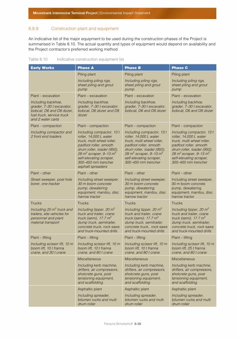
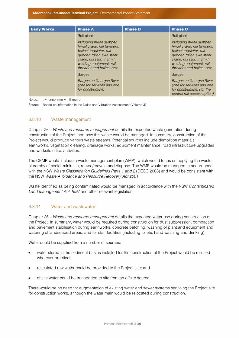
An indicative list of the major equipment to be used during the construction phases of the Project is
summarised in Table 8.10. The actual quantity and types of equipment would depend on availability and
the Project contractor’s preferred working method.
Table 8.10 Indicative construction equipment list
Early Works Phase A Phase B Phase C
Piling plant
Including piling rigs,
sheet piling and grout
pump
Piling plant
Including piling rigs,
sheet piling and grout
pump
Piling plant
Including piling rigs,
sheet piling and grout
pump
Plant – excavation
Including backhoe,
grader, 7–30 t excavator,
bobcat, D6 and D8 dozer,
fuel truck, service truck
and 2 water carts
Plant – excavation
Including backhoe,
grader, 7–30 t excavator,
bobcat, D6 dozer and D8
dozer
Plant – excavation
Including backhoe,
grader, 7–30 t excavator,
bobcat, D6 and D8 dozer
Plant – excavation
Including backhoe,
grader, 7–30 t excavator,
bobcat, D6 and D8 dozer
Plant – compaction
Including compactor and
2 front end loaders
Plant – compaction
Including compactor, 13 t
roller, 14,000 L water
truck, multi wheel roller,
padfoot roller, smooth
drum roller, loader (950),
28 m3 scraper, 9–13 m
3
self-elevating scraper,
300–450 mm trencher
asphalt spreaders
Plant – compaction
Including compactor, 13 t
roller, 14,000 L water
truck, multi wheel roller,
padfoot roller, smooth
drum roller, loader (950),
28 m3 scraper, 9–13 m
3
self-elevating scraper,
300–450 mm trencher
Plant – compaction
Including compactor, 13 t
roller, 14,000 L water
truck, multi wheel roller,
padfoot roller, smooth
drum roller, loader (950),
28 m3
scraper, 9–13 m3
self-elevating scraper,
300–400 mm trencher
Plant – other
Street sweeper, post hole
borer, one tracker
Plant – other
Including street sweeper,
30 m boom concrete
pump, dewatering
equipment, manitou, disc
harrow tractor
Plant – other
Including street sweeper,
30 m boom concrete
pump, dewatering
equipment, manitou, disc
harrow tractor
Plant – other
Including street sweeper,
30 m boom concrete
pump, dewatering
equipment, manitou, disc
harrow tractor
Trucks
Including 20 m3 truck and
trailers, site vehicles for
personnel and plant
material transport
Trucks
Including tipper, 20 m3
truck and trailer, crane
truck (semi), 17.7 m3
dump truck, semitrailer,
concrete truck, rock saws
and truck-mounted drills
Trucks
Including tipper, 20 m3
truck and trailer, crane
truck (semi), 17.7 m3
dump truck, semitrailer,
concrete truck,. rock saws
and truck-mounted drills
Trucks
Including tipper, 20 m3
truck and trailer, crane
truck (semi), 17.7 m3
dump truck, semitrailer,
concrete truck, rock saws
and truck-mounted drills
Plant – lifting
Including scissor lift, 10 m
boom lift, 10 t franna
crane, and 30 t crane
Plant – lifting
Including scissor lift, 10 m
boom lift, 10 t franna
crane, and 80 t crane
Plant – lifting
Including scissor lift, 10 m
boom lift, 10 t franna
crane, and 80 t crane
Plant – lifting
Including scissor lift, 10 m
boom lift, 25 t franna
crane, and 80 t crane
Miscellaneous
Including kerb machine,
drifters, air compressors,
shotcrete guns, post
tensioning equipment,
and scaffolding
Miscellaneous
Including kerb machine,
drifters, air compressors,
shotcrete guns, post
tensioning equipment,
and scaffolding
Miscellaneous
Including kerb machine,
drifters, air compressors,
shotcrete guns, post
tensioning equipment,
and scaffolding
Asphaltic plant
Including spreader,
bitumen rucks and multi
drum roller
Asphaltic plant
Including spreader,
bitumen rucks and multi
drum roller
Asphaltic plant
Including spreader,
bitumen rucks and multi
drum roller
Parsons Brinckerhoff 8-39
Early Works Phase A Phase B Phase C
Rail plant
Including hi-rail dumper,
hi-rail crane, rail tampers,
ballast regulator, rail
grinder, roller, skid steer
crane, rail saw, thermit
welding equipment, rail
threader and ballast box
Rail plant
Including hi-rail dumper,
hi-rail crane, rail tampers,
ballast regulator, rail
grinder, roller, skid steer
crane, rail saw, thermit
welding equipment, rail
threader and ballast box
Barges
Barges on Georges River
(one for services and one
for construction)
Barges
Barges on Georges River
(one for services and one
for construction) (for the
central rail access option)
Notes: t = tonne, mm = millimetre
Source: Based on information in the Noise and Vibration Assessment (Volume 3)
8.8.10 Waste management
Chapter 26 – Waste and resource management details the expected waste generation during
construction of the Project, and how this waste would be managed. In summary, construction of the
Project would produce various waste streams. Potential sources include demolition materials,
earthworks, vegetation clearing, drainage works, equipment maintenance, road infrastructure upgrades
and worksite office activities.
The CEMP would include a waste management plan (WMP), which would focus on applying the waste
hierarchy of avoid, minimise, re-use/recycle and dispose. The WMP would be managed in accordance
with the NSW Waste Classification Guidelines Parts 1 and 2 (DECC 2008) and would be consistent with
the NSW Waste Avoidance and Resource Recovery Act 2001.
Waste identified as being contaminated would be managed in accordance with the NSW Contaminated
Land Management Act 1997 and other relevant legislation.
8.8.11 Water and wastewater
Chapter 26 – Waste and resource management details the expected water use during construction of
the Project. In summary, water would be required during construction for dust suppression, compaction
and pavement stabilisation during earthworks, concrete batching, washing of plant and equipment and
watering of landscaped areas, and for staff facilities (including toilets, hand washing and drinking).
Water could be supplied from a number of sources:
water stored in the sediment basins installed for the construction of the Project would be re-used
wherever practical;
reticulated raw water could be provided to the Project site; and
offsite water could be transported to site from an offsite source.
There would be no need for augmentation of existing water and sewer systems servicing the Project site
for construction works, although the water main would be relocated during construction.
Parsons Brinckerhoff 8-40
8.8.12 Drainage infrastructure and erosion and sediment controls
During construction, existing drainage would be altered to better service the construction site and,
ultimately, the operational IMT. A network of detention basins, outlet culverts and channels would be
installed during Phase A and would service the Project construction.
The detention basins shown in Figure 7.20 to Figure 7.22 in Chapter 7 – Project built form and operations
would be established early in Phase A and used initially as temporary sedimentation basins to capture
sediment from surface stormwater flows during construction. These would then be upgraded to
permanent stormwater basins following completion of construction.
All stormwater trunk mains (east to west) would be established during Phase A, along with diversion of
the existing drainage culvert from the Defence National Storage Distribution Centre (DNSDC) site, and
outlet culverts and channels to the Georges River. An existing east to west channel would be temporarily
diverted during construction.
Erosion and sediment control measures would be installed, managed and maintained in accordance
with the ‘Blue Book’ (Managing Urban Stormwater: Soils and Construction Volume 1 (Landcom 2004))
and Managing Urban Stormwater: Soils and Construction, Volume 2D, Main Road Construction (DECC
2008). Such measures would seek to minimise erosion and sediment impacts from:
earthwork activities;
stockpile sites;
construction compounds and work site areas;
works within the vicinity of the Georges River and tributaries; and
construction of the bridge crossing the Georges River.
The application of specific erosion and sedimentation control measures for each construction element or
activity would be determined on site before construction, taking into account local constraints including
topography, available space and access requirements.
8.8.13 Dangerous and hazardous goods
During construction, hazardous materials including fuel (diesel, unleaded petrol) and cement and
concrete additives (batching plant materials) would be stored on site within bunded and specified
areas. No other dangerous goods would be transported to or stored on site during construction.
Storage and handling of fuel would be conducted in accordance with relevant Australian Standards.
Potential contaminants would not be stored near natural waterways; refuelling of machinery would be
undertaken at least 30 m from natural waterways in clearly marked designated areas designed to
contain spills and leaks. Chemical spill kits would be readily accessible to construction workers and all
hazardous materials spills and leaks would be reported to site managers. All appropriate spill
containment measures would be adopted and incorporated into the construction environmental
management plan (CEMP).
Parsons Brinckerhoff 8-41
8.9 Construction environmental management plan (CEMP)
A CEMP would be prepared for each construction phase of the Project, including for the Early Works
development phase. This CEMP would be prepared once the contractor has been appointed and before
work begins on site. The CEMP would provide a centralised mechanism through which all potential
environmental impacts relevant to the Project would be managed. It would outline a framework of
procedures and controls for managing environmental impacts during construction.
The CEMP would identify how environmental mitigation measures in this EIS and within all conditions of
approval would be incorporated into the construction of the Project, and would document mechanisms
for demonstrating compliance with all relevant conditions of approval for the Project.
The CEMP would also identify the auditing and inspection frameworks. An Environmental Management
Representative for the Project would be appointed to conduct regular audits against the CEMP,
conditions of approval and other relevant approvals.
The CEMP would also identify the framework for managing the following issues:
traffic and transport;
noise and vibration;
biodiversity;
hazards and risks;
soil contamination;
sediment control;
water quality and stormwater management;
air quality (including dust);
Aboriginal heritage;
European heritage;
landscape and rehabilitation;
light spill;
site servicing;
community liaison;
public safety; and
waste management.
The CEMP would identify the mitigation and monitoring measures to be implemented to minimise
environmental impacts, and establish the environmental performance objectives and targets for each
aspect in the form of measurable key performance indicators. The plan would be developed based on
best practice guidelines, industry standards and key recommendations.

Parsons Brinckerhoff 8-42
In addition to the CEMP, environmental work procedures and site specific environmental control maps
would be prepared and implemented during construction. As explained in Chapter 28 – Environment
management framework, provisional (framework) Environmental Management Plans (EMPs) have been
prepared for key environmental issues as part of this EIS (refer to Volume 2, Appendix H).
8.10 Project and construction definition process
As discussed in section 7.16 in Chapter 7 – Project built form and operations, the proposal concept
provides an indicative outline of the Project built form, as well as operations and activities associated
with the construction and operation of the IMT. Detailed IMT layout plans would be developed through
the detailed design phase and would be subject to further approval under the EP&A Act. Construction
plans and methods would be determined by the Project contractor after detailed design and before
construction begins.
It is important to note that, should the Project be granted Stage 1 SSD approval, detailed engineering
studies would be prepared to determine the optimal design for the Project. The final construction plan
and methods would be determined as part of detailed design and would be consistent with statutory
requirements (including any occupational health and safety regulations) and any associated conditions
of the Stage 1 SSD development approval.
The actual construction methods may vary from the description in this chapter as a result of the studies
conducted for detailed design and further investigations through the Stage 2 SSD approval process.
These studies would include:
detailed site survey;
geotechnical investigation works;
condition assessment of existing structures;
identification and location of underground utilities and services;
onsite conditions identified during pre-construction activities;
development of the design; and
community consultation, including consideration of submissions received.
As previously noted, the exception is the Early Works development phase, for which MIC is seeking
approval as part of the Stage 1 SSD development approval.
An environmental management framework to manage and mitigate impacts is presented in Chapter 28 –
Environment management framework. The final construction plan and methods would be consistent with
this framework.