chapter 9 induction linac - brookhaven national laboratory · · 2001-06-13chapter 9 induction...
TRANSCRIPT

Chapter 9
Induction Linac
9.1 Induction Accelerators for the Phase Rotator Sys-
tem
The principle of magnetic induction has often been applied to the acceleration of high-current beams in betatrons and in a variety of induction accelerators [1]. The inductionlinac (IL) consists of a simple nonresonant structure where the drive voltage is applied toan axially symmetric gap that encloses a toroidal ferromagnetic material. The change influx in the magnetic core induces an axial electric field that provides particle acceleration.This simple nonresonant (low-Q) structure acts as a single-turn transformer that can ac-celerate beams of hundreds of amperes to tens of kiloamperes, limited only by the driveimpedance. The IL is typically a low-gradient structure that can provide accelerationfields of varying shapes and time durations from tens of nanoseconds to several microsec-onds. The efficiency of the IL depends on the beam current, and can exceed 50% if thebeam current exceeds the magnetization current required by the ferromagnetic material.The acceleration voltage available is simply given by the expression V = AdB/dt. Hence,for a given cross sectional area A of material, the beam pulse duration influences theenergy gain. Furthermore, there is a premium put on minimizing the core diameter, asthis impacts the total weight, or cost, of the magnetic material. Indeed, the diameterdoubly impacts the cost of the IL, since the power to drive the cores is proportional tothe volume as well.
To meet the waveform requirements during the beam pulse, we make provisions inthe pulsing system to maintain the desired dB
dtduring the useful part of the acceleration
cycle. This can be done in either of two ways: by using the final stage of the pulseforming network (PFN) or by using the pulse-compensation network in close proximity
9 - 1
9.1. Induction Accelerators for the Phase Rotator System
Gradient(M
V/m)
time (ns)0 100 200 300 400
-1.0
0
1.0
!!!!!!
LLL
Ind 1
¥¥¥
Ind 2
JJInd 3
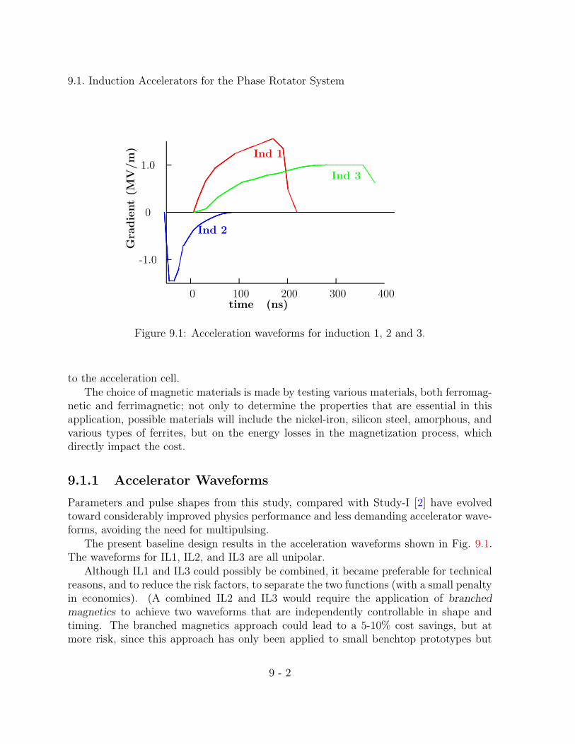
Figure 9.1: Acceleration waveforms for induction 1, 2 and 3.
to the acceleration cell.The choice of magnetic materials is made by testing various materials, both ferromag-
netic and ferrimagnetic; not only to determine the properties that are essential in thisapplication, possible materials will include the nickel-iron, silicon steel, amorphous, andvarious types of ferrites, but on the energy losses in the magnetization process, whichdirectly impact the cost.
9.1.1 Accelerator Waveforms
Parameters and pulse shapes from this study, compared with Study-I [2] have evolvedtoward considerably improved physics performance and less demanding accelerator wave-forms, avoiding the need for multipulsing.
The present baseline design results in the acceleration waveforms shown in Fig. 9.1.The waveforms for IL1, IL2, and IL3 are all unipolar.
Although IL1 and IL3 could possibly be combined, it became preferable for technicalreasons, and to reduce the risk factors, to separate the two functions (with a small penaltyin economics). (A combined IL2 and IL3 would require the application of branchedmagnetics to achieve two waveforms that are independently controllable in shape andtiming. The branched magnetics approach could lead to a 5-10% cost savings, but atmore risk, since this approach has only been applied to small benchtop prototypes but
9 - 2

9.1. Induction Accelerators for the Phase Rotator System
not to presently operating induction accelerators. This approach will be examined inAppendix B.)
9.1.2 Magnetic Material
A number of induction linac have been constructed in the past that cover the pulseduration of the three units required by the Neutrino Factory. None of these accelerators,however, has gradients and energy gains that are as high. To satisfy the requirements inan economically reasonable design, it is imperative to choose a magnetic material, and apulsing system, that minimize the cost but still achieve the reliability and performancerequired.
In the past two decades, great strides have been made in the development of a magneticmaterial that is replacing all previous ones in the 60-Hz power industry because of itslow loss, ease of manufacturing, and low cost. Several alloys are made in ribbon formby rapidly quenching a stream of molten material on a cold rotating drum. The ribbonthickness is typically 25 µm and can be of any width from 5 to 20 cm. Because theribbon is so thin, and has higher resistivity than other ferromagnetic materials, it isdirectly applicable to short pulse applications. In short pulse applications where the rateof magnetization (dB/dt) is very high, tens of volts are generated between the layers ofribbon when it is wound into a toroid. Thin insulation such as 2-4 µm Mylar must beused between layers to insure that the ribbon layers are sufficiently insulated to hold offthe voltage generated.
The soft magnetic properties can be improved by annealing. Unfortunately, thisprocedure, although well below the crystallization temperature, embrittles the material,making it nearly impossible to wind into a toroid. Annealing can be done after windingif the insulating material between layers has a sufficiently high melting point. Annealingis not an option when Mylar is used. Coatings have been developed that allow annealingafter winding, but at the present time they are not fully developed and do not hold offsufficient voltage per turn. Because the losses at high magnetization rates are almostentirely due to the eddy current losses, very little is lost in our application using thematerial “as cast” or unannealed.
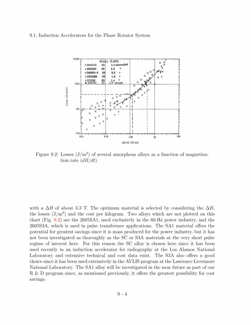
To choose the appropriate alloy of this amorphous material it is important to measurethe properties such as flux swing (∆B) and magnetization (∆H) at the appropriate pulseduration or magnetization rate (dB/dt). Figure 9.2 shows the losses in J/m3, at differentrates of magnetization. It can be seen that above T/µs the losses increase linearly withmagnetization rate. From Fig. 9.2 it appears that the lowest loss material is the alloy2705M with the lowest ∆B of about 1.4 T while the highest loss material is 2605CO
9 - 3
9.1. Induction Accelerators for the Phase Rotator System
Figure 9.2: Losses (J/m3) of several amorphous alloys as a function of magnetiza-tion rate (dB/dt).
with a ∆B of about 3.3 T. The optimum material is selected by considering the ∆B,the losses (J/m3) and the cost per kilogram. Two alloys which are not plotted on thischart (Fig. 9.2) are the 2605SA1, used exclusively in the 60-Hz power industry, and the2605S3A, which is used in pulse transformer applications. The SA1 material offers thepotential for greatest savings since it is mass produced for the power industry, but it hasnot been investigated as thoroughly as the SC or S3A materials at the very short pulseregime of interest here. For this reason the SC alloy is chosen here since it has beenused recently in an induction accelerator for radiography at the Los Alamos NationalLaboratory and extensive technical and cost data exist. The S3A also offers a goodchoice since it has been used extensively in the AVLIS program at the Lawrence LivermoreNational Laboratory. The SA1 alloy will be investigated in the near future as part of ourR & D program since, as mentioned previously, it offers the greatest possibility for costsavings.
9 - 4
9.1. Induction Accelerators for the Phase Rotator System
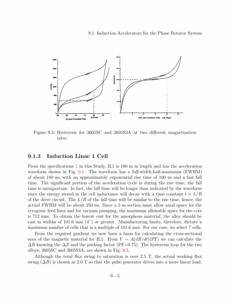
Figure 9.3: Hysteresis for 2605SC and 2605S3A at two different magnetizationrates.
9.1.3 Induction Linac 1 Cell
From the specifications 1 in this Study, IL1 is 100 m in length and has the accelerationwaveform shown in Fig. 9.1. The waveform has a full-width-half-maximum (FWHM)of about 180 ns, with an approximately exponential rise time of 100 ns and a fast falltime. The significant portion of the acceleration cycle is during the rise time; the falltime is unimportant. In fact, the fall time will be longer than indicated by the waveformsince the energy stored in the cell inductance will decay with a time constant t = L/Rof the drive circuit. The L/R of the fall time will be similar to the rise time, hence, theactual FWHM will be about 250 ns. Since a 1-m section must allow axial space for thecryogenic feed lines and for vacuum pumping, the maximum allowable space for the coreis 712 mm. To obtain the lowest cost for the amorphous material, the alloy should becast in widths of 101.6 mm (4”) or greater. Manufacturing limits, therefore, dictate amaximum number of cells that is a multiple of 101.6 mm. For our case, we select 7 cells.
From the required gradient we now have a basis for calculating the cross-sectionalarea of the magnetic material for IL1. From V = A(dB/dt)(PF) we can calculate the∆R knowing the ∆Z and the packing factor (PF=0.75). The hysteresis loop for the twoalloys, 2605SC and 2605S3A, are shown in Fig. 9.3.
Although the total flux swing to saturation is over 2.5 T, the actual working fluxswing (∆B) is chosen as 2.0 T so that the pulse generator drives into a more linear load.
9 - 5
9.1. Induction Accelerators for the Phase Rotator System
The required voltage for each of the seven cells that constitute one meter of accelerationis 214.3 kV. The actual cross-section is
A = (r2 − r1) ∗ w =V∆t
∆B(PF )(9.1)
so
(r2 − r1) = frac(214.3× 10³)(250× 10−9)(2.0)(0.75)(r2 − r1) = 0.325 m. (9.2)
The inside radius of the core is set by the outside radius of the superconducting solenoidat a minimum of 0.4 m. Preliminary calculations of the leakage flux at the solenoid gapsindicate that this flux, which is orthogonal to the magnetization flux, can be of the orderof a few thousand gauss at the 0.4 m radius. From previous tests for the Advanced TestAccelerator (ATA) and the Dual-Axis Radiographic Hydro Test (DARHT) [3] accelerator,this is acceptable. Nonetheless, this issue should be investigated further with laboratorytests to insure that the flux swing of the induction cell is not reduced by this stray flux. Tobe conservative, we set the inside radius of the actual amorphous material at 500 mm. Themagnetizing current and the losses can now be calculated. The magnetizing force ∆H =∆I/πd where d is the average diameter or d = r2+r1 = 1.35 m. From Fig. 9.3 for a 0.25 µssaturation time we find that the magnetizing force is ∆H = 1200 A/m or ∆I = 5,087 A,and the loss is U = V ∆I ∆t or U = (214.3×10³)(5.087×10³)(250×10−9) = 272.5 J/cell.The magnetic material volume, including the mylar insulation is V = π(r22 − r21)(∆z), orV=0.151 m3. With a packing factor of 0.75, the actual volume of amorphous materialis 0.113 m3, and at a density of 7290 kg/m3 it weighs 825 kg. The core losses couldalso have been calculated from Fig. 9.2, which shows that the losses per cubic meter at amagnetization rate dB/dt = 2.0 T/0.25 µs, are 2 kJ/m3 for a total of 262 J, slightly lowerthan the estimate above. The loss calculations above determine the drive power requiredby the pulse generator for one cell. For seven cells P = 7V I, and with V = 214.3 kV,I = 5.09 kA, P = 7.63 GW and the impedance Z = V/7I = 6.0Ω.
9.1.3.1 High Voltage Design of Cell
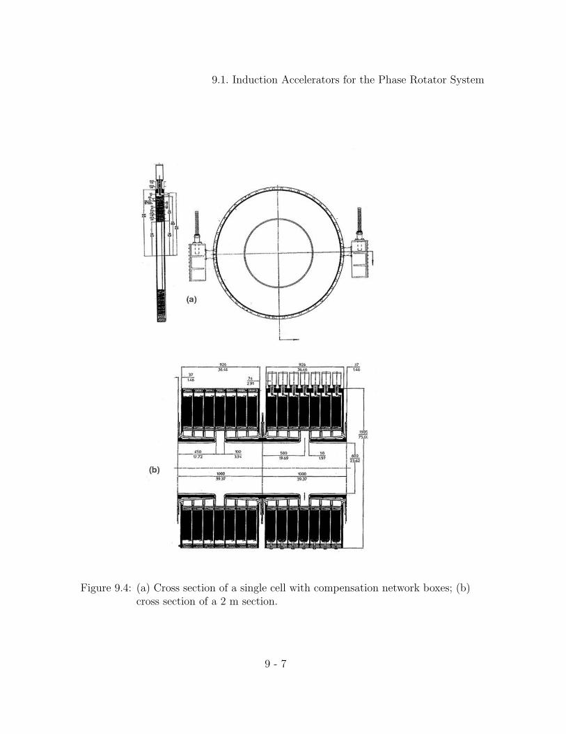
Figure 5.8 shows a cross section of the induction cell. The cell is driven by two high voltagecables at 180. The high voltage cables plug into two connections, of the type used on theDARHT accelerator, that are part of the compensation network box. The accelerationgap is 1 cm and is oil filled. From Fig. 9.5, which shows the voltage breakdown in oil fordifferent pulse durations and surface areas, it appears that the safety factors are morethan adequate, that is, the actual breakdown is about twice the operating voltage. Thehighest voltage stress occurs at the outside radius of the core where one half of the driving
9 - 6
9.1. Induction Accelerators for the Phase Rotator System
Figure 9.4: (a) Cross section of a single cell with compensation network boxes; (b)cross section of a 2 m section.
9 - 7

9.1. Induction Accelerators for the Phase Rotator System
Figure 9.5: Short-pulse voltage breakdown in oil.
voltage appears from each side of the core to ground. Insulation is done with ten layersof 50 µm mylar with oil impregnation.
The oil-to-vacuum interface insulator is designed so that on the vacuum side the fieldlines form a 30 or greater angle with the insulator to achieve the highest possible voltageholding. The empirical curve in Fig. 9.6 shows the voltage flashover for different angles.For our design, the maximum surface gradient on the insulator is nearly one order ofmagnitude lower.
The highest voltage gradient occurs between the solenoid housings. Here the spacingis 100 mm and the radius is 30 mm. Using a cylindrical geometry, the maximum gradientis about 150–200 kV/cm. Figure 9.7 shows field emission after 200 ns for different types ofsurfaces. A standard electropolished stainless steel surface is marginally acceptable for ourpurposes. To be prudent, the surfaces should be greened. In a subsequent optimization,the gradient will be reduced somewhat by redesigning the nose pieces.
9.1.4 Induction Linac 2 Cell
From the specifications shown in Fig. 9.1 for IL2, the deceleration pulse has an unspecifiedrise time (from zero to a negative value) and a fall time of about 50 ns (from a negative
9 - 8

9.1. Induction Accelerators for the Phase Rotator System
Figure 9.6: Flashover voltage with a 30-ns pulse for different cone angles.
value back to zero) that is a significant portion of the waveform.
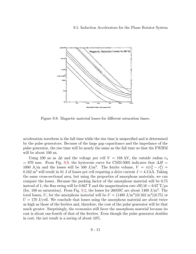
Induction accelerators with pulse durations of less than 100 ns have traditionally usednickel-zinc ferrites as the magnetic material of choice. This choice was the appropriateone a decade or two ago when the last short-pulse induction accelerator was built, sincethe amorphous materials at that time were not of a very high quality and were moreexpensive than they are today. The choice of ferrites also was logical if one comparestheir losses to those of amorphous materials at saturation times of 50 ns. We can see fromFig. 9.8 that, if full saturation is achieved in 50 ns, the losses for ferrites (CMD 5005)are about 800 J/m3 while the losses for amorphous materials (2605SC) are about oneorder of magnitude higher. That is, even though the flux swing for amorphous materialsis five times greater than those of the ferrites, the losses are more than ten times greater(at full saturation). On the other hand, the cost of ferrites has quadrupled in the pasttwo decades while the cost of amorphous materials has decreased considerably. Thismakes it imperative to take another look at using amorphous materials of the same crosssection (volume) as the ferrites. Then the flux swing would be much lower than that atfull saturation, as would be the magnetization rates, and hence, the losses. To make thebest comparison, designs were made using both the ferrites and the amorphous materials.Using the standard 101.6 mm width (w) and a ∆B (from Fig. 9.9) for the ferrite CMD-5005 the area A = w(r2 − r1) = V∆t/∆B. From Fig. 9.1 the significant part of the
9 - 9

9.1. Induction Accelerators for the Phase Rotator System
Figure 9.7: Current density after 200 ns for different surface preparations.
9 - 10
9.1. Induction Accelerators for the Phase Rotator System
Figure 9.8: Magnetic material losses for different saturation times.
acceleration waveform is the fall time while the rise time is unspecified and is determinedby the pulse generators. Because of the large gap capacitance and the impedance of thepulse generator, the rise time will be nearly the same as the fall time so that the FWHMwill be about 100 ns.
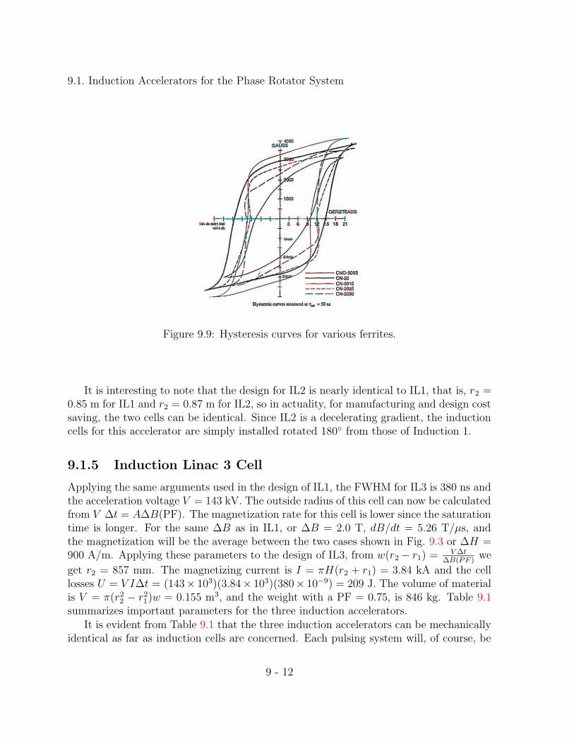
Using 100 ns as ∆t and the voltage per cell V = 188 kV, the outside radius r2= 870 mm. From Fig. 9.9, the hysteresis curve for CMD-5005 indicates that ∆H =1000 A/m and the losses will be 500 J/m3. The ferrite volume, V = π(r22 − r21) =0.162 m3 will result in 81 J of losses per cell requiring a drive current I = 4.3 kA. Takingthe same cross-sectional area, but using the proporties of amorphous materials, we cancompare the losses. Because the packing factor of the amorphous material will be 0.75instead of 1, the flux swing will be 0.667 T and the magnetization rate dB/dt = 6.67 T/µs(for, 100 ns saturation). From Fig. 9.2, the losses for 2605SC are about 1400 J/m3. Thetotal losses, U , for the amorphous material will be U = (1400 J/m3)(0.162 m3)(0.75) orU = 170 J/cell. We conclude that losses using the amorphous material are about twiceas high as those of the ferrites and, therefore, the cost of the pulse generator will be thatmuch greater. Surprisingly, the economics still favor the amorphous material because itscost is about one-fourth of that of the ferrites. Even though the pulse generator doublesin cost, the net result is a saving of about 10%.
9 - 11
9.1. Induction Accelerators for the Phase Rotator System
Figure 9.9: Hysteresis curves for various ferrites.
It is interesting to note that the design for IL2 is nearly identical to IL1, that is, r2 =0.85 m for IL1 and r2 = 0.87 m for IL2, so in actuality, for manufacturing and design costsaving, the two cells can be identical. Since IL2 is a decelerating gradient, the inductioncells for this accelerator are simply installed rotated 180 from those of Induction 1.
9.1.5 Induction Linac 3 Cell
Applying the same arguments used in the design of IL1, the FWHM for IL3 is 380 ns andthe acceleration voltage V = 143 kV. The outside radius of this cell can now be calculatedfrom V ∆t = A∆B(PF). The magnetization rate for this cell is lower since the saturationtime is longer. For the same ∆B as in IL1, or ∆B = 2.0 T, dB/dt = 5.26 T/µs, andthe magnetization will be the average between the two cases shown in Fig. 9.3 or ∆H =900 A/m. Applying these parameters to the design of IL3, from w(r2 − r1) = V∆t
∆B(PF )we
get r2 = 857 mm. The magnetizing current is I = πH(r2 + r1) = 3.84 kA and the celllosses U = V I∆t = (143× 103)(3.84× 10³)(380× 10−9) = 209 J. The volume of materialis V = π(r22 − r21)w = 0.155 m3, and the weight with a PF = 0.75, is 846 kg. Table 9.1summarizes important parameters for the three induction accelerators.
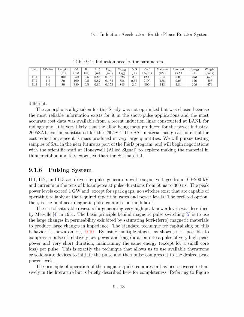
It is evident from Table 9.1 that the three induction accelerators can be mechanicallyidentical as far as induction cells are concerned. Each pulsing system will, of course, be
9 - 12
9.1. Induction Accelerators for the Phase Rotator System
Table 9.1: Induction accelerator parameters.
Unit MV/m Length ∆t IR OR Vcell Wcell ∆B ∆H Voltage Current Energy Weight(m) (ns) (m) (m) (m3) (kg) (T) (A/m) (kV) (kA) (J) (tons)
IL1 1.5 100 250 0.5 0.85 0.151 826 2.0 1200 214 5.09 273 578IL2 1.5 80 100 0.5 0.87 0.162 886 0.67 2100 188 9.05 170 496IL3 1.0 80 380 0.5 0.86 0.155 846 2.0 900 143 3.84 209 474
different.The amorphous alloy taken for this Study was not optimized but was chosen because
the most reliable information exists for it in the short-pulse applications and the mostaccurate cost data was available from a recent induction linac constructed at LANL forradiography. It is very likely that the alloy being mass produced for the power industry,2605SA1, can be substituted for the 2605SC. The SA1 material has great potential forcost reduction, since it is mass produced in very large quantities. We will pursue testingsamples of SA1 in the near future as part of the R&D program, and will begin negotiationswith the scientific staff at Honeywell (Allied Signal) to explore making the material inthinner ribbon and less expensive than the SC material.
9.1.6 Pulsing System
IL1, IL2, and IL3 are driven by pulse generators with output voltages from 100–200 kVand currents in the tens of kiloamperes at pulse durations from 50 ns to 300 ns. The peakpower levels exceed 1 GW and, except for spark gaps, no switches exist that are capable ofoperating reliably at the required repetition rates and power levels. The prefered option,then, is the nonlinear magnetic pulse compression modulator.
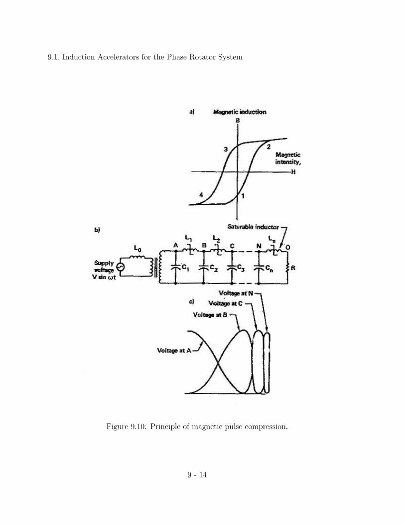
The use of saturable reactors for generating very high peak power levels was describedby Melville [4] in 1951. The basic principle behind magnetic pulse switching [5] is to usethe large changes in permeability exhibited by saturating ferri-(ferro) magnetic materialsto produce large changes in impedance. The standard technique for capitalizing on thisbehavior is shown on Fig. 9.10. By using multiple stages, as shown, it is possible tocompress a pulse of relatively low power and long duration into a pulse of very high peakpower and very short duration, maintaining the same energy (except for a small coreloss) per pulse. This is exactly the technique that allows us to use available thyratronsor solid-state devices to initiate the pulse and then pulse compress it to the desired peakpower levels.
The principle of operation of the magnetic pulse compressor has been covered exten-sively in the literature but is briefly described here for completeness. Referring to Figure
9 - 13
9.1. Induction Accelerators for the Phase Rotator System
Figure 9.10: Principle of magnetic pulse compression.
9 - 14

9.1. Induction Accelerators for the Phase Rotator System
5.14, capacitor C1 charges through inductance L0 until inductance L1 saturates, becom-ing much less than L0. Once this happens, C2 will begin to charge from C1 through L1satbut since L1sat is much less than L0, C2 charges more rapidly than C1 did. This processcontinues through the successive stages until Cn discharges into the load through Lnsat.
To make this process efficient, we design each of these successive stages so that satu-ration occurs at the peak of the voltage waveform. Segment 1 to 2 in the hysteresis loopof Fig. 9.10 is the active, or high-permeability, region during which the inductor impedescurrent flow; the leveling off of the curve at point 2, reached at the peak of the voltagewaveform, indicates core saturation when the inductor achieves a low impedance. Duringsegment 2 to 4, the core is reset to its original state, ready for the next cycle.
9.1.6.1 IL1 pulse compressor
The requirement for IL1 is to generate an acceleration pulse shape and gradient shownin Fig. 4.5. Each accelerator cell previously described produces a voltage of 214 kV; afterthe beam traverses 700 of these cells it has gained 150 MV of energy. From Table 9.1,the necessary drive current for one cell is 5.09 kA for a duration (FWHM) of 250 ns. Aspreviously mentioned, no switches exist that can produce this type of pulse directly. Byinvestigating the optimum operating voltage and current of the switches, the requiredstages of compression are decided. Since thyristors have limits in dI/dt of several kA/µsand voltage limits of a few kV it can be seen that a large number of them in series andparallel combination will be required. Thyratrons also have limits on dI/dt and voltagebut these limits are at least one order of magnitude greater than thyristors. Thyristorshave practically unlimited life while thyratrons have an operating life of the order of20,000 hours. Even taking into consideration replacement costs, the thyratrons offer asimpler and more economical pulse compression system (fewer stages).
For technical and economic reasons, the pulse compression system is designed to driveone meter or seven induction cells. The total energy required is U = 273×7 = 1.9 kJ plusthat needed to make up the additional losses incurred in the pulse compression scheme.The 500 J pulse compression system (Fig. 9.12), designed to replace the Advanced TestAccelerator spark gaps, achieved efficiencies greater than 90%. Allowing for 5% losses inthe thyratron switches, 5% losses in the resonant charging and 5% in the power supply,the total input energy per pulse needed is 2.5 kJ and, at 15 Hz average repetition rate,the power for seven cells P = 38.2 kW; the total power for IL1 is Pt = 3.82 MW.
9 - 15
9.1. Induction Accelerators for the Phase Rotator System
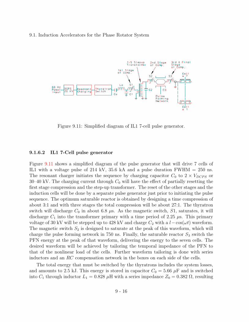
Figure 9.11: Simplified diagram of IL1 7-cell pulse generator.
9.1.6.2 IL1 7-Cell pulse generator
Figure 9.11 shows a simplified diagram of the pulse generator that will drive 7 cells ofIL1 with a voltage pulse of 214 kV, 35.6 kA and a pulse duration FWHM = 250 ns.The resonant charger initiates the sequence by charging capacitor C0 to 2 × VDCPS or30–40 kV. The charging current through C0 will have the effect of partially resetting thefirst stage compression and the step-up transformer. The reset of the other stages and theinduction cells will be done by a separate pulse generator just prior to initiating the pulsesequence. The optimum saturable reactor is obtained by designing a time compression ofabout 3:1 and with three stages the total compression will be about 27:1. The thyratronswitch will discharge C0 in about 6.8 µs. As the magnetic switch, S1, saturates, it willdischarge C1 into the transformer primary with a time period of 2.25 µs. This primaryvoltage of 30 kV will be stepped up to 428 kV and charge C2 with a l−cos(ωt) waveform.The magnetic switch S2 is designed to saturate at the peak of this waveform, which willcharge the pulse forming network in 750 ns. Finally, the saturable reactor S3 switch thePFN energy at the peak of that waveform, delivering the energy to the seven cells. Thedesired waveform will be achieved by tailoring the temporal impedance of the PFN tothat of the nonlinear load of the cells. Further waveform tailoring is done with seriesinductors and an RC compensation network in the boxes on each side of the cells.
The total energy that must be switched by the thyratrons includes the system losses,and amounts to 2.5 kJ. This energy is stored in capacitor C0 = 5.66 µF and is switchedinto C1 through inductor L1 = 0.828 µH with a series impedance Z0 = 0.382 Ω, resulting
9 - 16

9.1. Induction Accelerators for the Phase Rotator System
Figure 9.12: 500 J Mag 1-D magnetic pulse compression modulator driving theETA II accelerator.
9 - 17

9.1. Induction Accelerators for the Phase Rotator System
in a peak half-sine-wave current of 28 kA, for a peak power of 2.3 GW. Several thyratronoptions are available. The highest continuous-power thyratrons are the ceramic-envelopeunits, while the glass-envelope units are capable of nearly as high a peak power with lowaverage power capability. Since the average power is moderate (38 kW) the appropriatechoice for technical and economic reasons is the glass- envelope unit. To carry the 78 kApeak current, twelve parallel devices are used. To insure current sharing, each thyratronwill switch its own capacitor which is C0/12 = 0.47 µF. Except for thyratron replace-ment every 20,000 hours or more of operation, the pulse compression systems should bemaintenance free since all components are passive devices.
9.1.6.3 IL2 pulse compressor
The pulse for the IL2 accelerator has a duration (FWHM) of 100 ns. Assuming anadditional 5% loss (since the pulse compression system has to go one step further), thetotal input energy for seven cells would be U = 1.6 kJ and, at 15 Hz, would result in apower requirement of 24 kW. The total power requirement for IL1 is 1.9 MW, and itspulse duration is 100 ns FWHM. The shorter pulse duration would dictate an additionalstage of pulse compression on the system described for IL1. However, since the energyfor IL2 is 68% of IL1, it is possible to achieve the shorter pulse duration with the samenumber of stages simply by initiating the compression process with a shorter pulse. Thedesign of each stage, of course, will be different and the transformer will have a step-upof 12:1. For IL2, C0 = 3.78 µF and the compression for three stages is 36 for an initialdischarge time of 3.6 µs with L0 = 0.347 µH and Z0 = 0.303Ω. The peak current requiredof the twelve thyratrons is 99 kA, or 8.25 kA each.
9.1.6.4 IL3 pulse compressor
The pulse duration for IL3 is 380 ns FWHM. A pulse compression similar to IL1 withthree stages is used. The transformer will have a step-up of about 10:1, and the threesaturable reactors will be similar to those in IL1. The energy at the input is U = 2 kJand, at 15 Hz average repetition rate, the input power per seven cells is 29.3 kW andthe total imput power is Pt = 2.34 MW. With the input energy of 2 kJ, the capacitor C0= 4.34 µF and with an initial discharge time t0 = 10.3µs, the inductor L0 = 2.46 µH,and the series impedance Z0 = 0.753Ω, which results in a peak current of 40 kA. Thetotal power required for IL1, IL2 and IL3 at 15 Hz average repetition rate is 8.2 MW.Including the efficiency of 90% for the DC charging power supplies, the total 60-Hz powerrequirement (see Table. 9.2) will be very nearly 9 MW.
9 - 18

9.1. Induction Accelerators for the Phase Rotator System
Table 9.2: Energy and power requirements. ∗ Assuming 90% efficiency.Unit Length Pulser energy Total energy Ptotal (15 Hz)∗
(m) (J/m) (kJ) (kW)IL1 100 2548 254.8 4247IL2 80 1590 126.9 2115IL3 80 1951 156.1 2602Total power required from grid 8964
9.1.7 Mechanical Systems
In order to achieve the desired gradient for the three induction linacs, the induction cellsare driven by the pulsing system in units of seven. Hence, these cells are mechanicallyassembled into one module by bolting together seven cells.
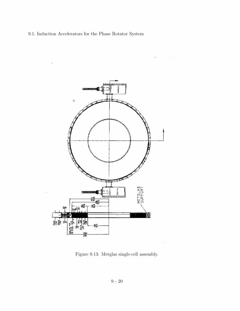
The individual cores would be assembled at the plant. The mandrel on which theamorphous material is wound supports the complete core. An additional support cradleis included on the OD of the core to insure that there is no sagging (Fig. 9.13). Asspecified under electrical requirements, the cores are wound with 101.6 mm wide ribbonwith 3 µm mylar between layers and protruding 3 mm beyond the ribbon. As assumedearlier in this section, the complete core has a packing factor (PF) of about 75%.
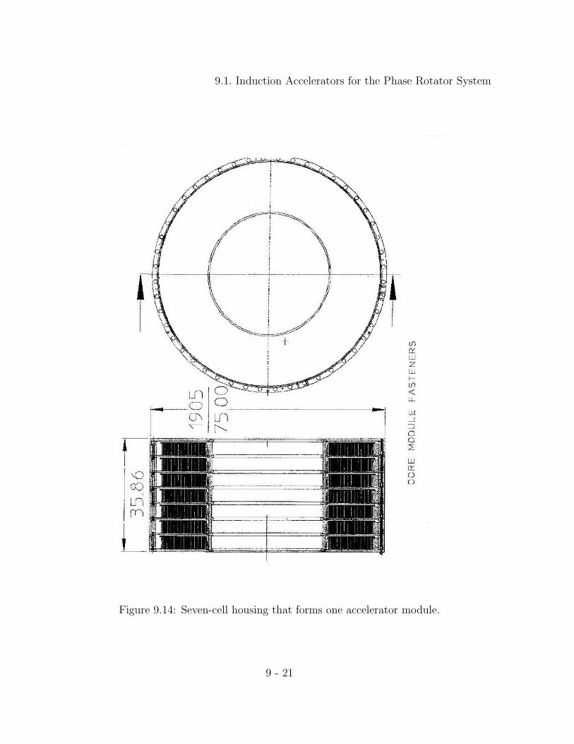
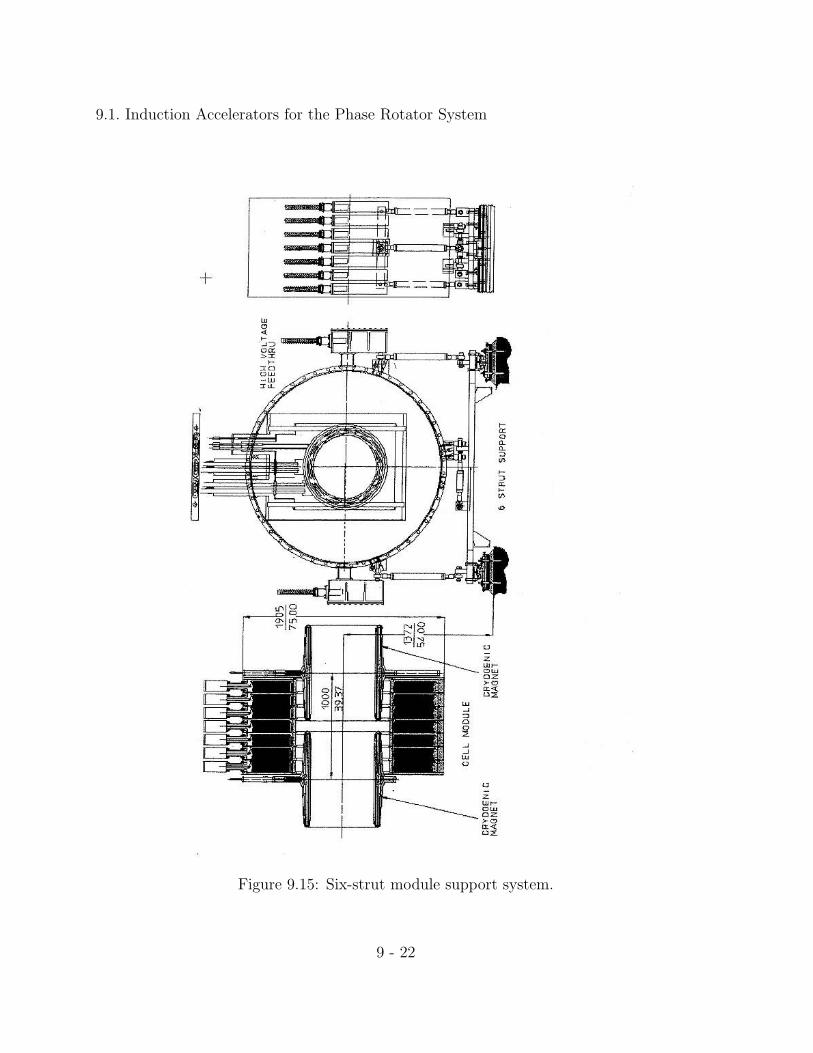
The high-voltage insulator, which is the oil-to-vacuum interface, is assembled in sevensections for each module and voltage grading of each section is provided by makingcontact with the appropriate cell. Each section has a gradient ring, which insures thatthe field lines enter the insulator at an angle of about 30 to provide maximum voltageholding (Fig. 9.6). The seven section insulator is made of “Mykroy/Mycalex” and will beglued together as in the DARHT accelerator (Fig. 9.14). The induction module housingis fabricated and assembled using seven large rings fastened together by outside fixturessimilar to those used in the Relativistic Two-beam Accelerator (RTA) at LBNL. Thewhole module is supported on the OD from these rings by a six-strut support system(Fig. 9.15). The support system allows for excellent alignment of each module withrespect adjacent modules and the absolute beam line.
The vacuum system will consist of turbo pumps and cryopumps located every 5-10modules. These pumps will be connected to a roughing line alongside the accelerator.Beam position and total current diagnostics will also be located at the pump-out station.Each module with its downstream SC solenoid magnet is assembled and aligned prior toinstallation in the beamline. After installation in the beamline, the module is alignedand the vacuum seal is fastened.
9 - 19
9.1. Induction Accelerators for the Phase Rotator System
Figure 9.13: Metglas single-cell assembly.
9 - 20
9.1. Induction Accelerators for the Phase Rotator System
Figure 9.14: Seven-cell housing that forms one accelerator module.
9 - 21
9.1. Induction Accelerators for the Phase Rotator System
Figure 9.15: Six-strut module support system.
9 - 22

Bibliography
[1] N.C. Christofilos, High-Current Linear Induction Accelerator for Electrons, Rev. Sci.Instrum., 35, July (1964).
[2] N. Holtkamp and D. Finley, eds., A Feasibility Study of a Neutrino Source Based ona Muon Storage Ring, Fermilab-Pub-00/108-E (2000), Chapter 5, p. 5-4.http://www.fnal.gov/projects/muon collider/nu-factory/nu-factory.html
[3] M.J. Burns, et al., DARHT Accelerators Update and Plans for Initial Operation,Proc. 1999 Acc. Conf., p.617.
[4] W.S. Melville, The Use of Saturable Reactors as Discharge Devices for Pulse Gener-ators, Institute of Electrical Engineers, 98-Part III, May (1951).
[5] D.L Birx, An Investigation into the Repetition Rate Limitations of Magnetic Switches,UCRL-87278, (1982), Lawrence Livermore National Laboratory.
9 - 23