chapter 9: pumps, compressors and turbines - uprm · pdf filechapter 9: pumps, compressors and...
TRANSCRIPT
Ruiz Rivera Ketzya Y.
Ruiz Santiago Luis D.
Ruiz Torres Héctor
Santiago González Paola
Tirado Aponte Vanessa
Chapter 9: Pumps, Compressors and Turbines
9.1 Positive Displacement Pump
A pump is a machine used to displace fluid. Generally, is used to increase the pressure of a liquid adding
energy to the hydraulic system, to move the fluid of a zone of smaller pressure or altitude to another one
of greater pressure or altitude. The pump transforms the mechanical energy into hydraulic energy of the
incompressible fluid and exerts work on a liquid dWa.o
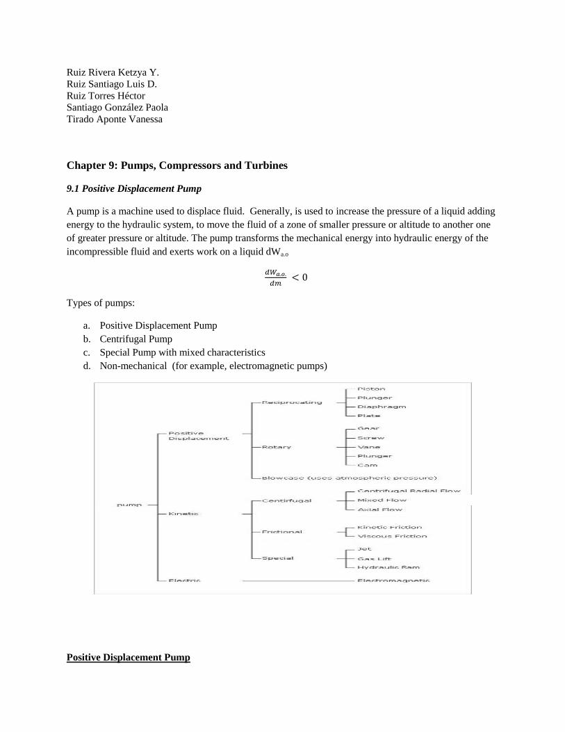
Types of pumps:
a. Positive Displacement Pump
b. Centrifugal Pump
c. Special Pump with mixed characteristics
d. Non-mechanical (for example, electromagnetic pumps)
Positive Displacement Pump
These pumps guide the fluid throughout their entire trajectory. The movement of the positive
displacement consists of the movement of a fluid caused by the diminution of the volume of a camera.
The movement that originates the energy exchange can have an alternative movement (piston) or rotating
motion.
*Rotary type
The vacuum created by the rotation of the pump captures and draws in the liquid. The pump carries out
the work to remove the air of the lines. The pumps rotate at a slow steady speed because the clearance
between the rotating pump and the outer edge are very close.
*Reciprocating-type
This type of pump has an expanding cavity on the suction side and a decreasing cavity of on the side of
the discharge. The fluid in the pumps and the cavity in the side of the suction are extended. The liquid
flows out of the discharge, while the cavity collapses. The volume is constant in each cycle of the
operation.
Cycle of Operation of a positive displacement pump
1. The piston is dissuaded to create emptiness in the cavity
2. The spring is open and enters liquid to the cavity.
3. While the low piston, the liquid enters.
4. As the piston returns to the starting point, the pressure in the cavity increases.
5. The valve is opened, once the pressure exceeds the pressure of exit.
6. The piston pushes the fluid outside the cavity.
7. Begin the process again.
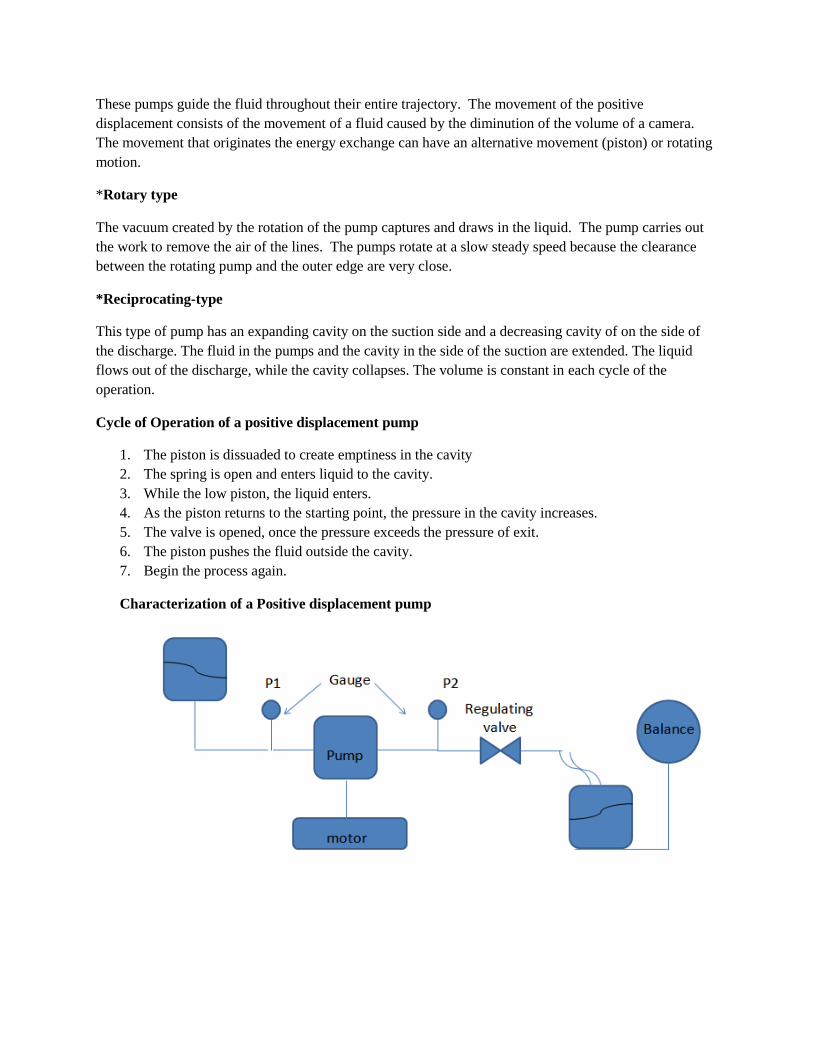
Characterization of a Positive displacement pump
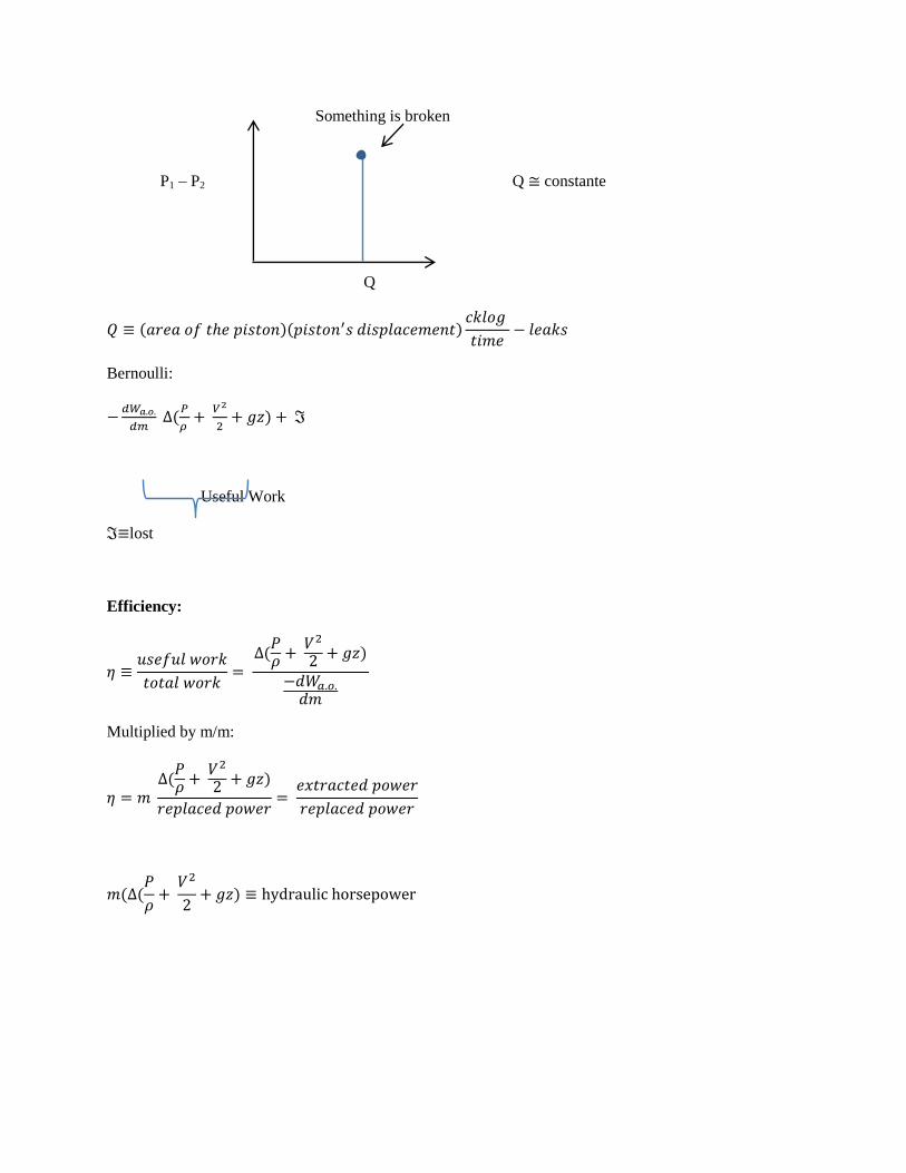
Something is broken
P1 – P2 Q constante
Q
( )( )
Bernoulli:
(
)
Useful Work
lost
Efficiency:
(
)
Multiplied by m/m:
(
)
( (
)
Example 9.1 A pump, pumps 50gal/min of water of a pressure of 30psia to 100psia. The changes of
elevation and speed are negligible. The motor of the pump supply 2.80hp. What is the efficiency of the
pump?
m= (50gal/min)(8.33lbm/gal) = 417 lbm/min
(
) (
)(
)(
)
=0.73
9.2 Centrifugal Pumps
The centrifugal pumps elevate the kinetic energy of the fluid and later they turn this energy to work of
injection. The fluid enters by the center of the bun. The pump has blades to lead the fluid. By centrifugal
force the fluid is driven to the outside and is gathered by the body of the pump. Later it is lead towards the
tabulators of exit or the following bun. The produced centrifugal force depends of the speed in the
periphery of the impeller and of the density of the liquid, but the energy that is applied by mass unit of the
liquid is independent of the density of the liquid. In series they increase the pressure substantially. They
require liquid to begin to work and its efficiency varies between 0.5 and 0.9. The centrifugal pump has
two sections:
1. The impeller increases the kinetic energy of the fluid.
2. The diffuser turns the kinetic energy to work of injection.
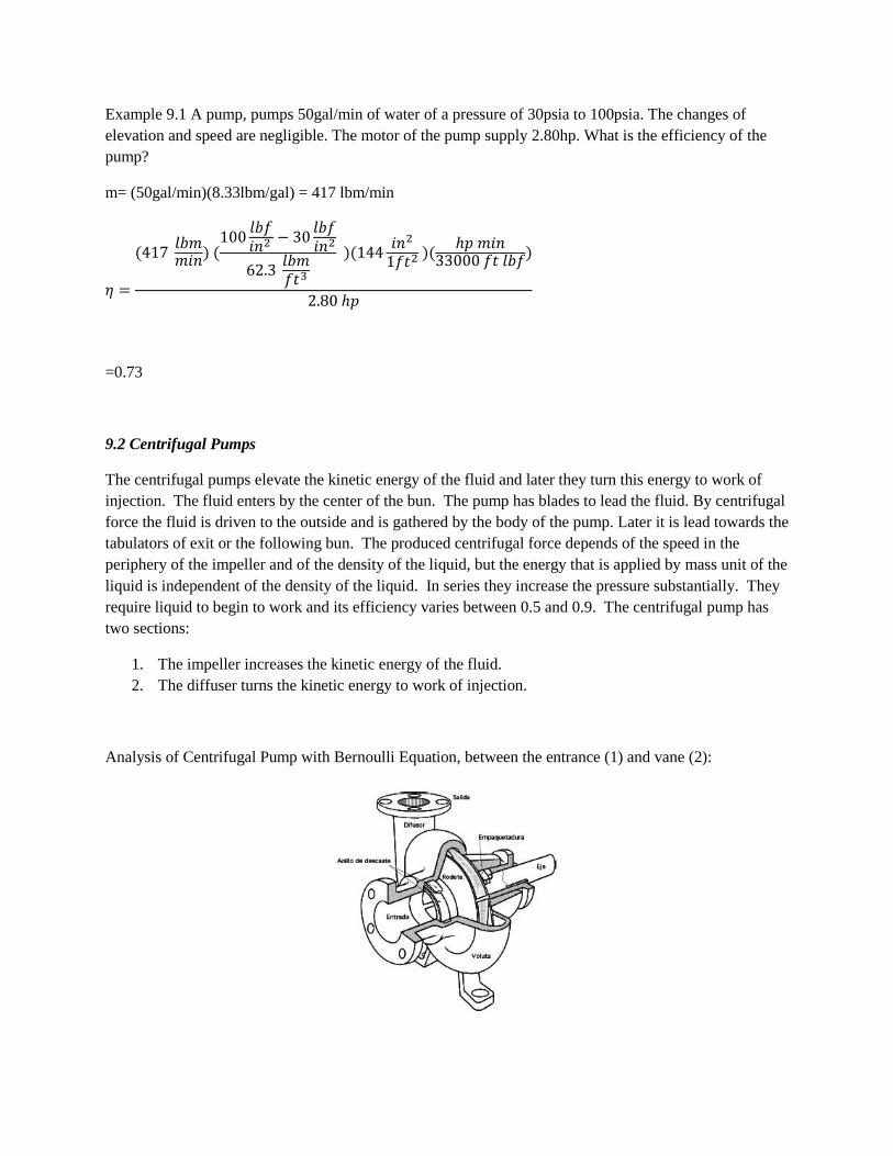
Analysis of Centrifugal Pump with Bernoulli Equation, between the entrance (1) and vane (2):
Tangential speed = (radio)(angular velocity)
Analysis of the vanes (2) and the exist (3):
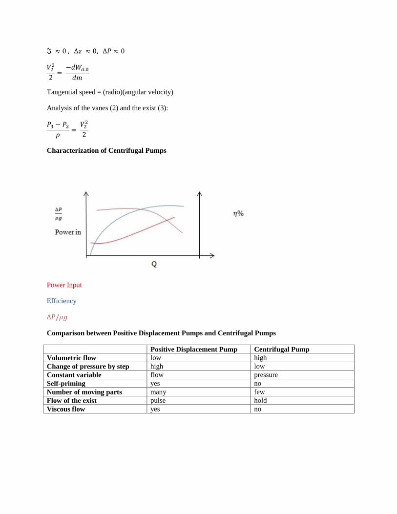
Characterization of Centrifugal Pumps
Power Input
Efficiency
Comparison between Positive Displacement Pumps and Centrifugal Pumps
Positive Displacement Pump Centrifugal Pump
Volumetric flow low high
Change of pressure by step high low
Constant variable flow pressure
Self-priming yes no
Number of moving parts many few
Flow of the exist pulse hold
Viscous flow yes no
9.3-9.4 Compressors
The main difference of the compressors in respect to pumps and turbines is that the density of
the fluid (solid, liquid or gas) changes significantly from the inlet to the outlet of the
compressible flow machine. A gas compressor is a mechanical device that increases the
pressure of a gas by reducing its volume. Compressors are essentially pumps that add energy to
the fluid and cause a significant pressure rise and as such it causes an increase in density.
Compression process increase temperature. They are used a lot in engineering in:
-refrigeration system
-electric energy generation
-interior of airplane motors
-to compress gases in the feed of pneumatic system
-submarines
-pipeline transport
Types of compressors:
I. Positive displacement:
1) Rotary:
a) Single- Acting
b) Double-Acting
c) Diaphragm
2) Reciprocating:
a) Scroll
b) Lobe
c) Liquid ring
d) Vane
II. Dynamic:
a) Radial (Centrifugal) - are essentially centrifugal pumps that use gas instead of liquid
as the working fluid. They are high pressure rise, low flow rate and work at much
higher speed. The amount of compression is given by the total pressure ratio given
by: PR= P02/P 01 where pressure is absolute. Adiabatic in where there’s not heat
transfer compression of the gas causes an increase in temperature and requires more
work than isothermal (constant temperature) compression of a gas. Multistaging is
used in high pressure ratio compressors. If each stage has the same pressure ratio it is
given by: PR^n where n is the number of stages.
b) Axial- are dynamic rotating compressors that use arrays of fan-like airfoils to
progressively compress the working fluid. They are used where there is a requirement
for a high flow rate or a compact design. Axial compressors can have high
efficiencies; around 90%. One disadvantage is low increase in pressure by stage.
9.5-9.6 Compressors efficiency/Motors and Turbines
As with any other type of machine, system, or process, it is one thing to develop
expressions for an ideal system and another thing is the actual system, since we know that ideal
systems do not exist. Hence we use the term efficiency to determine how close to ideality the
machine really is. Fluid machines like pumps and compressors operate applying work,
specifically they do work on the fluid so they add energy to the flow.
Efficiency of pumps
We define the efficiency of the pump, ηp as the ratio between the work required by the ideal
pump and the actual work delivered by the pump (both often expressed in units of horsepower or
kilowatts)
( )
However, while this is a common, general expression for the efficiency of a pump, it is
natural that it can be expressed in a different manner. There are a few other ways to express
efficiencies of these fluid machines:
*Volumetric efficiency and volumetric loss
The volumetric loss is due to leakage of fluid from the back surface of the impeller hub
plate and the casing, or other pump components. The volumetric efficiency is
( )
where q is the volume flow out of the pump and ql is the volume flow of the leakage occurring.
*Mechanical efficiency and mechanical loss
Because of the friction between the distinct parts of a pump there is a mechanical loss in
the components that reduces the power that is transferred from the motor to the impellers. The
mechanical efficiency is defined as
( )
where P is the mechanical power added and Pl is the power lost in the transfer from the motor to
the impeller.
*Hydraulic efficiency and hydraulic loss
Hydraulic loss is also due to friction only this time it’s the friction between the fluid and
the walls, acceleration or retardation of the fluid flow and a change in the direction of flow. The
hydraulic loss is defined as
( )
where w is the work supplied from the pump and wl is the work lost.
*Total loss and overall efficiency
The total loss is as simple as the sum of the hydraulic, volumetric, and mechanical losses.
The overall efficiency of the pump η is simply the product of the 3 efficiencies,
η p= ηh ηm ηv (5)
This is an alternate expression for (1).
Efficiency of compressors.
In general terms the efficiency is also a ratio of work, although the expression changes a
bit here. The efficiency of the compressor ηc is defined as
( )
The isentropic compressor is the ideal one. Recall that isentropic means that there is no change
in the entropy of the system which is an adiabatic and reversible system or process, and we know
that this is not the case in the real world. From thermodynamics we know that for an irreversible
process or flow to be isentropic there must be an adequate heat transfer so that it remains at a
constant entropy, hence it is not adiabatic.
Motors and Turbines
The positive displacement pump can work as a motor if the valve timers are adjusted
which creates an analogy to the vapor motor
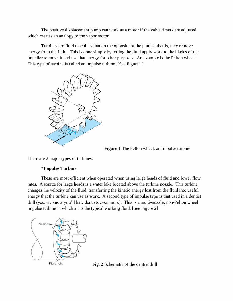
Turbines are fluid machines that do the opposite of the pumps, that is, they remove
energy from the fluid. This is done simply by letting the fluid apply work to the blades of the
impeller to move it and use that energy for other purposes. An example is the Pelton wheel.
This type of turbine is called an impulse turbine. [See Figure 1].
Figure 1 The Pelton wheel, an impulse turbine
There are 2 major types of turbines:
*Impulse Turbine
These are most efficient when operated when using large heads of fluid and lower flow
rates. A source for large heads is a water lake located above the turbine nozzle. This turbine
changes the velocity of the fluid, transferring the kinetic energy lost from the fluid into useful
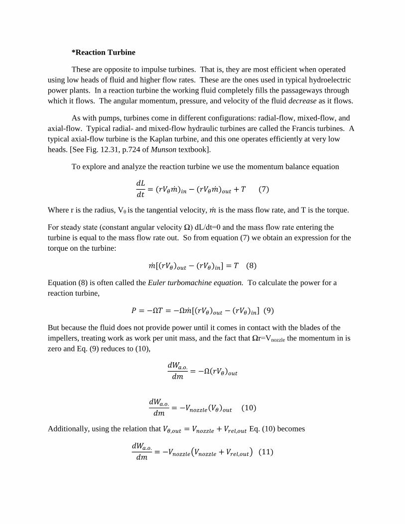
energy that the turbine can use as work. A second type of impulse type is that used in a dentist
drill (yes, we know you’ll hate dentists even more). This is a multi-nozzle, non-Pelton wheel
impulse turbine in which air is the typical working fluid. [See Figure 2]
Fig. 2 Schematic of the dentist drill
*Reaction Turbine
These are opposite to impulse turbines. That is, they are most efficient when operated
using low heads of fluid and higher flow rates. These are the ones used in typical hydroelectric
power plants. In a reaction turbine the working fluid completely fills the passageways through
which it flows. The angular momentum, pressure, and velocity of the fluid decrease as it flows.
As with pumps, turbines come in different configurations: radial-flow, mixed-flow, and
axial-flow. Typical radial- and mixed-flow hydraulic turbines are called the Francis turbines. A
typical axial-flow turbine is the Kaplan turbine, and this one operates efficiently at very low
heads. [See Fig. 12.31, p.724 of Munson textbook].
To explore and analyze the reaction turbine we use the momentum balance equation
( ) ( ) ( )
Where r is the radius, Vθ is the tangential velocity, is the mass flow rate, and T is the torque.
For steady state (constant angular velocity Ω) dL/dt=0 and the mass flow rate entering the
turbine is equal to the mass flow rate out. So from equation (7) we obtain an expression for the
torque on the turbine:
( ) ( ) ( )
Equation (8) is often called the Euler turbomachine equation. To calculate the power for a
reaction turbine,
( ) ( ) ( )
But because the fluid does not provide power until it comes in contact with the blades of the
impellers, treating work as work per unit mass, and the fact that Ωr=Vnozzle the momentum in is
zero and Eq. (9) reduces to (10),
( )
( ) ( )
Additionally, using the relation that Eq. (10) becomes
( ) ( )
The optimal velocity of the nozzle is
9.7 Turbine and Motor Efficiency
Reaction turbines are less efficient than impulse turbines and we denote that the efficiency of a
turbine is, in fact, is the inverse of the pump efficiency.
ηt ≡ ηp-1
≡
The efficiency for liquids: The maximum work done corresponds to Vout = 0; F = 0
The efficiency for gases: The maximum work done corresponds to Vout = 0; ∆Sprocess = 0
For our concern, the efficiency of a lot of thermal engines in today’s industry oscillates between
the 3% (97% of wasted heat) for conversion of thermal energy systems of the ocean, 25% for
most car engines, 35% for power plant generators of supercritical carbon, and the 60% for a gas
turbine of combine cycle with vapor cooling. All these process obtain their efficiency (or loses)
because of the temperature depression through them. For example, the thermal energy
conversion systems of the ocean uses a temperature difference between the water in the surface
and the water in the deep ocean, it means a 25 C difference so its efficiency should be low. By
the other hand, combined cycle turbines use natural gas burning to warm air until 1530°C,
meaning a 1500°C difference so its efficiency should be high when adding the vapor cooling
cycle.
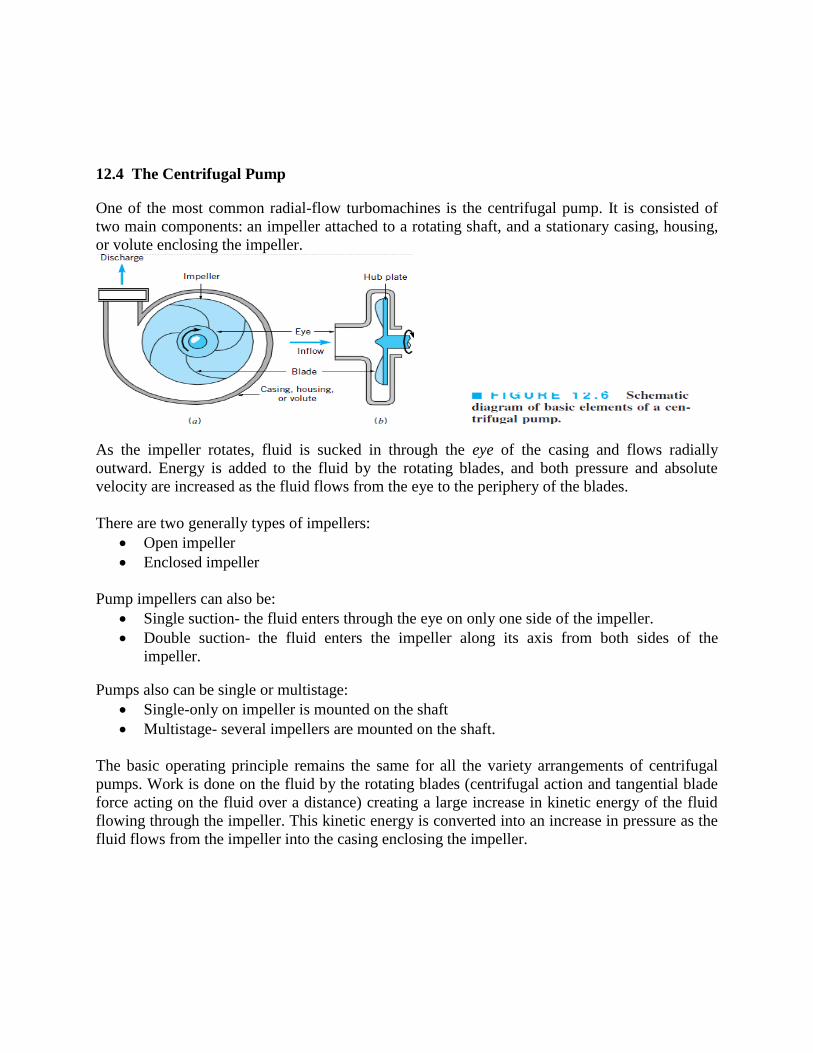
12.4 The Centrifugal Pump
One of the most common radial-flow turbomachines is the centrifugal pump. It is consisted of
two main components: an impeller attached to a rotating shaft, and a stationary casing, housing,
or volute enclosing the impeller.
As the impeller rotates, fluid is sucked in through the eye of the casing and flows radially
outward. Energy is added to the fluid by the rotating blades, and both pressure and absolute
velocity are increased as the fluid flows from the eye to the periphery of the blades.
There are two generally types of impellers:
Open impeller
Enclosed impeller
Pump impellers can also be:
Single suction- the fluid enters through the eye on only one side of the impeller.
Double suction- the fluid enters the impeller along its axis from both sides of the
impeller.
Pumps also can be single or multistage:
Single-only on impeller is mounted on the shaft
Multistage- several impellers are mounted on the shaft.
The basic operating principle remains the same for all the variety arrangements of centrifugal
pumps. Work is done on the fluid by the rotating blades (centrifugal action and tangential blade
force acting on the fluid over a distance) creating a large increase in kinetic energy of the fluid
flowing through the impeller. This kinetic energy is converted into an increase in pressure as the
fluid flows from the impeller into the casing enclosing the impeller.
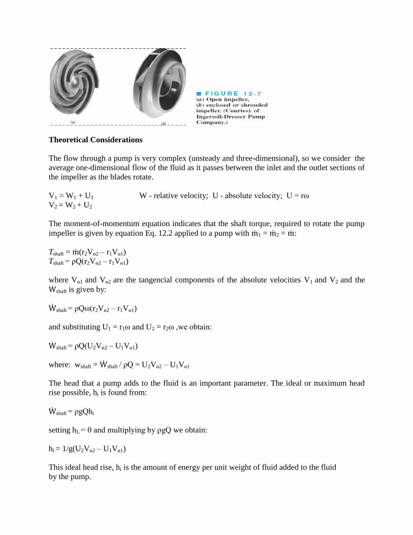
Theoretical Considerations
The flow through a pump is very complex (unsteady and three-dimensional), so we consider the
average one-dimensional flow of the fluid as it passes between the inlet and the outlet sections of
the impeller as the blades rotate.
V1 = W1 + U1 W - relative velocity; U - absolute velocity; U = rω
V2 = W2 + U2
The moment-of-momentum equation indicates that the shaft torque, required to rotate the pump
impeller is given by equation Eq. 12.2 applied to a pump with ṁ1 = ṁ2 = ṁ:
Tshaft = ṁ(r2Vө2 – r1Vө1)
Tshaft = ρQ(r2Vө2 – r1Vө1)
where Vө1 and Vө2 are the tangencial components of the absolute velocities V1 and V2 and the
Ẇshaft is given by:
Ẇshaft = ρQω(r2Vө2 – r1Vө1)
and substituting U1 = r1ω and U2 = r2ω ,we obtain:
Ẇshaft = ρQ(U2Vө2 – U1Vө1)
where: wshaft = Ẇshaft / ρQ = U2Vө2 – U1Vө1
The head that a pump adds to the fluid is an important parameter. The ideal or maximum head
rise possible, hi is found from:
Ẇshaft = ρgQhi
setting hL = 0 and multiplying by ρgQ we obtain:
hi = 1/g(U2Vө2 – U1Vө1)
This ideal head rise, hi is the amount of energy per unit weight of fluid added to the fluid
by the pump.
An appropriate relationship between the flowrate and the pump ideal head rise can be
obtained as follows. Often the fluid has no tangential component of velocity or swirl, as
it enters the impeller; i.e., the angle between the absolute velocity and the tangential direction
is α = 90°C, then:
hi = U2Vө2 / g
from Fig. 12.8c: cot β2 = U2 - Vө2 / Vr2
Using Q = 2πr2b2Vr2, where b2 is the impeller blade height at radius r2. Combining these
equations yields:
hi = (U22 / g) – (U2cot β2 Q/ 2πr2b2g)
This equation shows that the ideal or maximum head rise for a centrifugal pump varies linearly
with Q for a given blade geometry and angular velocity. The ideal head rise can be calculated
with the Euler turbomachine equation (See example 12.2 Munson, p.697).
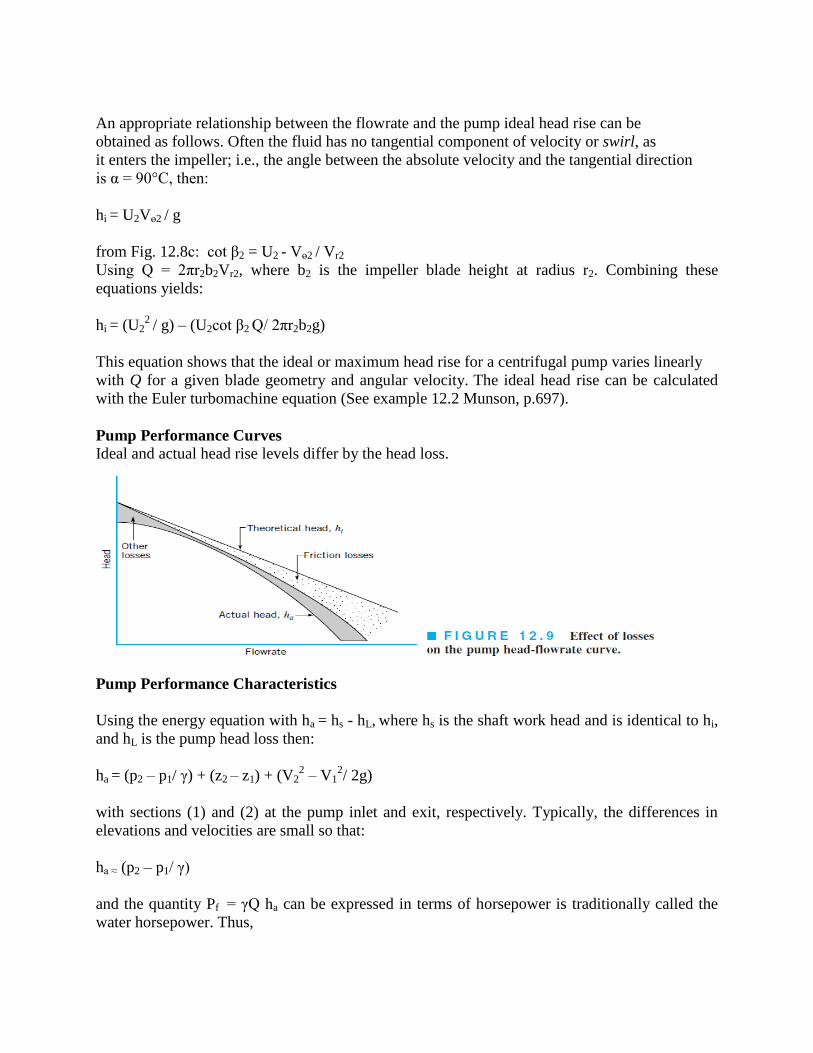
Pump Performance Curves
Ideal and actual head rise levels differ by the head loss.
Pump Performance Characteristics
Using the energy equation with ha = hs - hL, where hs is the shaft work head and is identical to hi,
and hL is the pump head loss then:
ha = (p2 – p1/ γ) + (z2 – z1) + (V22 – V1
2/ 2g)
with sections (1) and (2) at the pump inlet and exit, respectively. Typically, the differences in
elevations and velocities are small so that:
ha ≈ (p2 – p1/ γ)
and the quantity Pf = γQ ha can be expressed in terms of horsepower is traditionally called the
water horsepower. Thus,
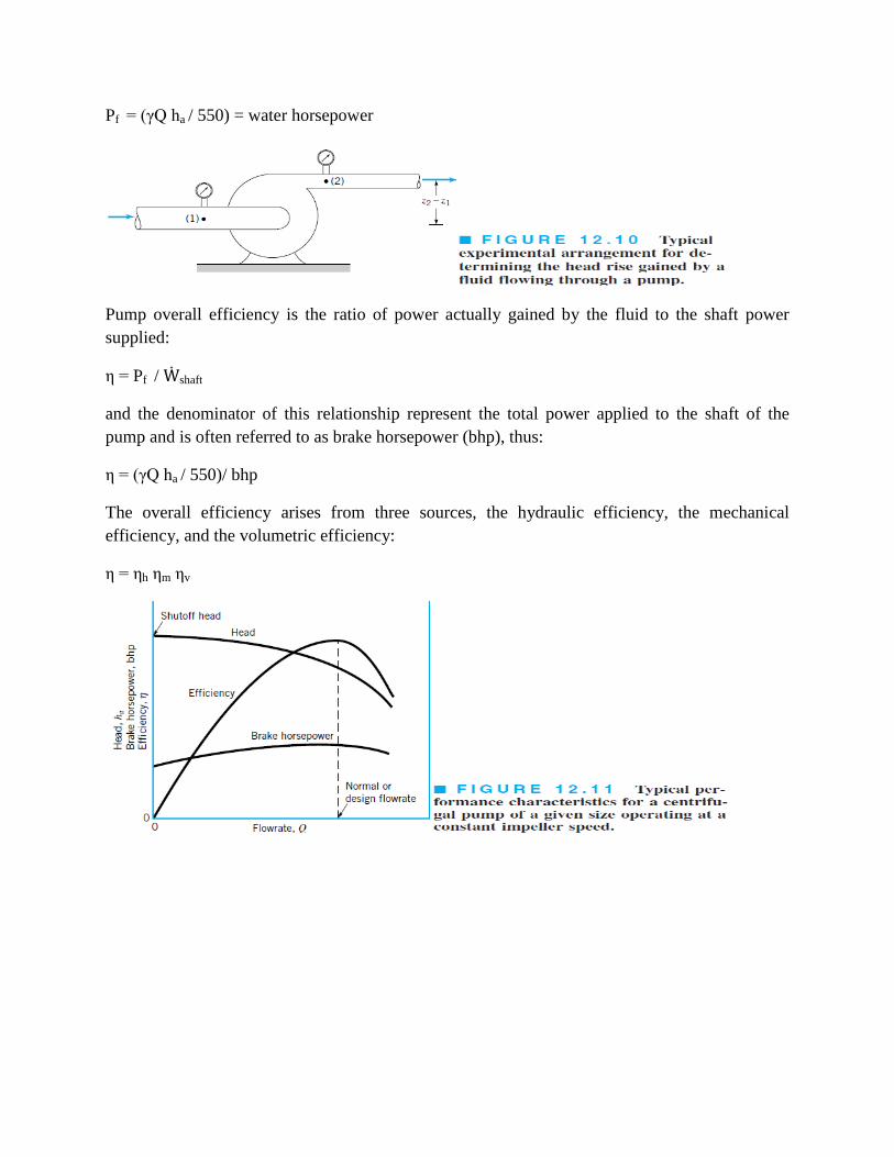
Pf = (γQ ha / 550) = water horsepower
Pump overall efficiency is the ratio of power actually gained by the fluid to the shaft power
supplied:
η = Pf / Ẇshaft
and the denominator of this relationship represent the total power applied to the shaft of the
pump and is often referred to as brake horsepower (bhp), thus:
η = (γQ ha / 550)/ bhp
The overall efficiency arises from three sources, the hydraulic efficiency, the mechanical
efficiency, and the volumetric efficiency:
η = ηh ηm ηv
Net Positive Suction Head (NPSH)
The position reference for the elevation head passes through the centerline of the pump impeller
inlet. This difference is called the net positive suction head (NPSH) so that:
NPSH = (ps / γ) + (Vs2
/ 2g) + ∑ hL
NPSHA = (patm / γ) – z1 - ∑ hL – pv / γ
There are actually two values of NPSH of interest. The first is the required NPSH, denoted
NPSHR, that must be maintained, or exceeded, so that cavitation will not occur. The second
value for NPSH of concern is the available NPSH, denoted NPSHA which represents the head
that actually occurs for the particular flow system. For proper pump operation it is necessary
that: NPSHA ≥NPSHR. (See ex. 12.3, p. 702)
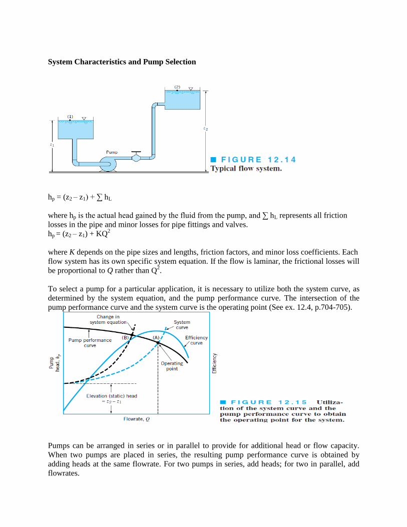
System Characteristics and Pump Selection
hp = (z2 – z1) + ∑ hL
where hp is the actual head gained by the fluid from the pump, and ∑ hL represents all friction
losses in the pipe and minor losses for pipe fittings and valves.
hp = (z2 – z1) + KQ2
where K depends on the pipe sizes and lengths, friction factors, and minor loss coefficients. Each
flow system has its own specific system equation. If the flow is laminar, the frictional losses will
be proportional to Q rather than Q2.
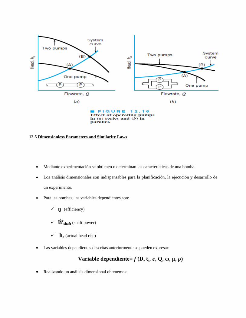
To select a pump for a particular application, it is necessary to utilize both the system curve, as
determined by the system equation, and the pump performance curve. The intersection of the
pump performance curve and the system curve is the operating point (See ex. 12.4, p.704-705).
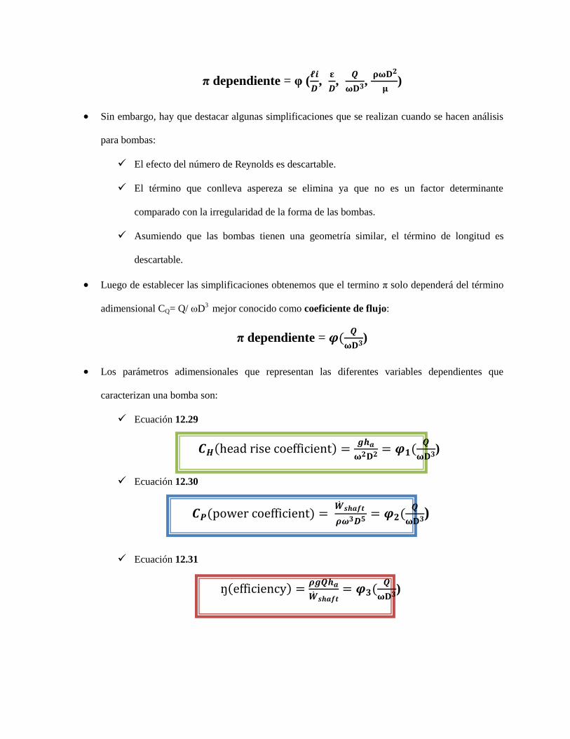
Pumps can be arranged in series or in parallel to provide for additional head or flow capacity.
When two pumps are placed in series, the resulting pump performance curve is obtained by
adding heads at the same flowrate. For two pumps in series, add heads; for two in parallel, add
flowrates.
12.5 Dimensionless Parameters and Similarity Laws
Mediante experimentación se obtienen o determinan las características de una bomba.
Los análisis dimensionales son indispensables para la planificación, la ejecución y desarrollo de
un experimento.
Para las bombas, las variables dependientes son:
ŋ (efficiency)
shaft (shaft power)
ha (actual head rise)
Las variables dependientes descritas anteriormente se pueden expresar:
Variable dependiente= f (D, ℓi, , Q, ω, μ, ρ)
Realizando un análisis dimensional obtenemos:
π dependiente = φ (
,
,
,
)
Sin embargo, hay que destacar algunas simplificaciones que se realizan cuando se hacen análisis
para bombas:
El efecto del número de Reynolds es descartable.
El término que conlleva aspereza se elimina ya que no es un factor determinante
comparado con la irregularidad de la forma de las bombas.
Asumiendo que las bombas tienen una geometría similar, el término de longitud es
descartable.
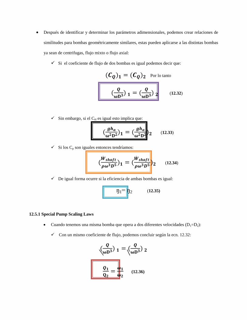
Luego de establecer las simplificaciones obtenemos que el termino π solo dependerá del término
adimensional CQ= Q/ ωD3 mejor conocido como coeficiente de flujo:
π dependiente = (
)
Los parámetros adimensionales que representan las diferentes variables dependientes que
caracterizan una bomba son:
Ecuación 12.29
( )
(
)
Ecuación 12.30
( )
(
)
Ecuación 12.31
( )
(
)
Después de identificar y determinar los parámetros adimensionales, podemos crear relaciones de
similitudes para bombas geométricamente similares, estas pueden aplicarse a las distintas bombas
ya sean de centrifugas, flujo mixto o flujo axial:
Si el coeficiente de flujo de dos bombas es igual podemos decir que:
( ) ( ) Por lo tanto
(
) (
) (12.32)
Sin embargo, si el CH es igual esto implica que:
(
) (
) (12.33)
Si los Cp son iguales entonces tendríamos:
(
) (
) (12.34)
De igual forma ocurre si la eficiencia de ambas bombas es igual:
ŋ1= ŋ2 (12.35)
12.5.1 Special Pump Scaling Laws
Cuando tenemos una misma bomba que opera a dos diferentes velocidades (D1=D2):
Con un mismo coeficiente de flujo, podemos concluir según la ecn. 12.32:
(
) (
)
(12.36)
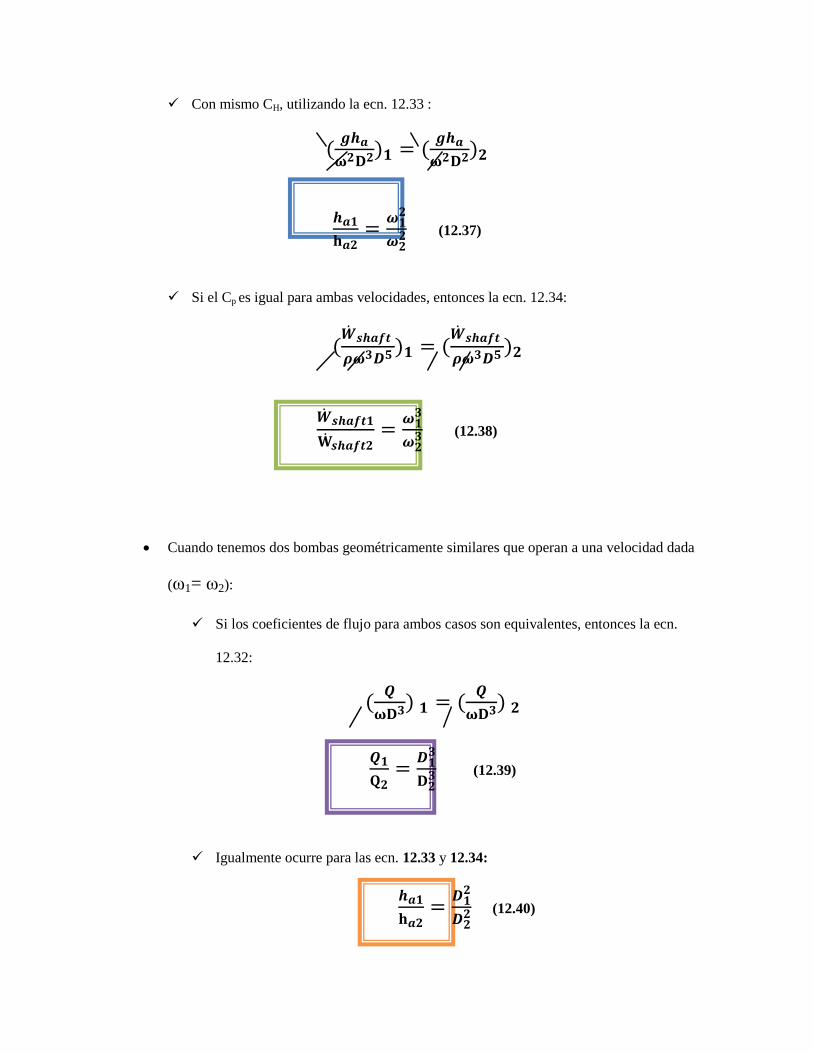
Con mismo CH, utilizando la ecn. 12.33 :
(
) (
)
(12.37)
Si el Cp es igual para ambas velocidades, entonces la ecn. 12.34:
(
) (
)
(12.38)
Cuando tenemos dos bombas geométricamente similares que operan a una velocidad dada
(ω1= ω2):
Si los coeficientes de flujo para ambos casos son equivalentes, entonces la ecn.
12.32:
(
) (
)
(12.39)
Igualmente ocurre para las ecn. 12.33 y 12.34:
(12.40)
(12.41)
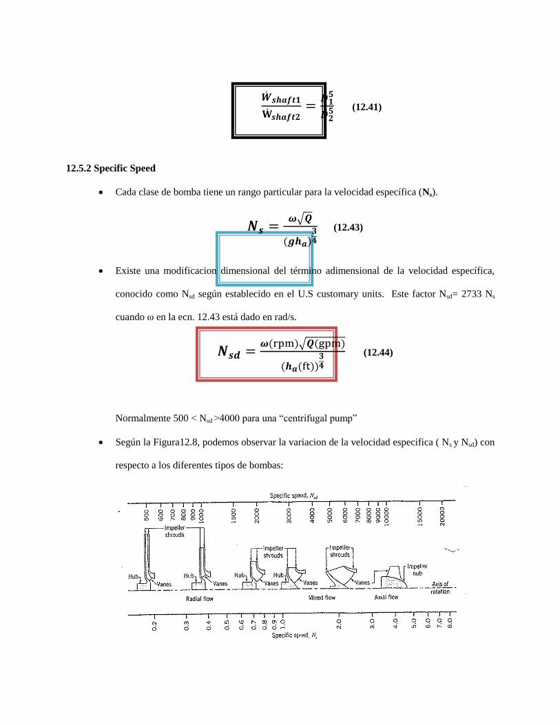
12.5.2 Specific Speed
Cada clase de bomba tiene un rango particular para la velocidad específica (Ns).
√
( )
(12.43)
Existe una modificacion dimensional del término adimensional de la velocidad específica,
conocido como Nsd según establecido en el U.S customary units. Este factor Nsd= 2733 Ns
cuando ω en la ecn. 12.43 está dado en rad/s.
( )√ ( )
( ( ))
(12.44)
Normalmente 500 < Nsd >4000 para una “centrifugal pump”
Según la Figura12.8, podemos observar la variacion de la velocidad especifica ( Ns y Nsd) con
respecto a los diferentes tipos de bombas:
12.5.3 Suction Specific Speed
Podemos relacionar la velocidad especifica (Ns) con el de “ suction specific speed” (Ss). Solo
se sustituye en la ecn. 12.43 la variable ha por el término NPSHR (net positive suction head):
√
( ( ))
(12.45)
De igual forma para la modificación dimensional:
( )√ ( )
( ( ))
(12.46)
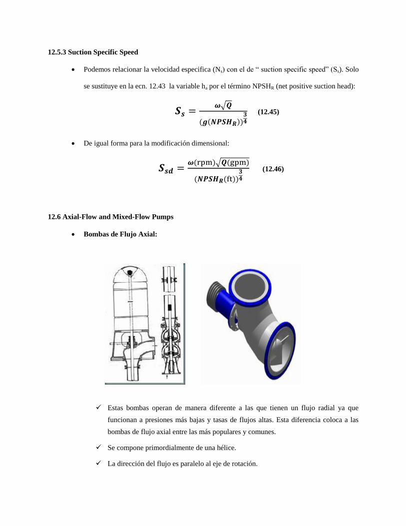
12.6 Axial-Flow and Mixed-Flow Pumps
Bombas de Flujo Axial:
Estas bombas operan de manera diferente a las que tienen un flujo radial ya que
funcionan a presiones más bajas y tasas de flujos altas. Esta diferencia coloca a las
bombas de flujo axial entre las más populares y comunes.
Se compone primordialmente de una hélice.
La dirección del flujo es paralelo al eje de rotación.
En este caso la presión es desarrollada por la fuerza tangencial ejercida por la hélice
en el fluido.
El diámetro del impulsor en el área de succión y en el área de descarga son iguales.
Las velocidades específicas que distinguen este tipo de bombas son las que exceden
el valor de 9000 (Nsd >9000) ya que el valor de ha (actual head rise) es bastante
pequeño.
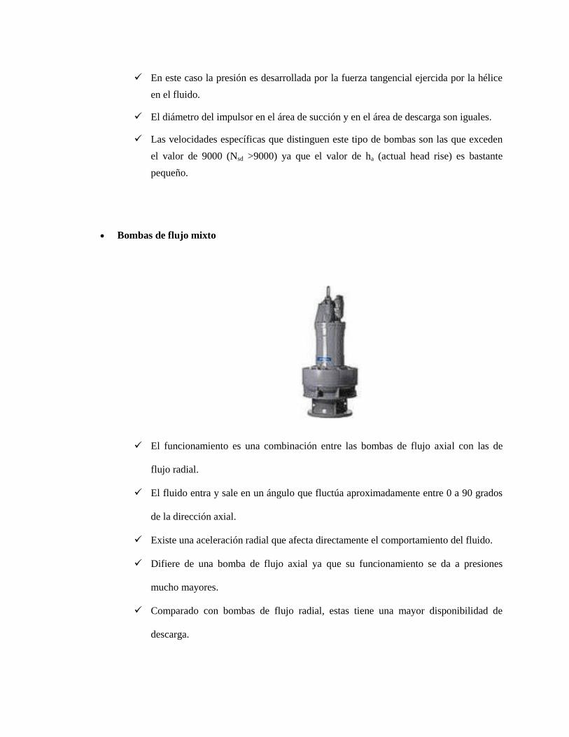
Bombas de flujo mixto
El funcionamiento es una combinación entre las bombas de flujo axial con las de
flujo radial.
El fluido entra y sale en un ángulo que fluctúa aproximadamente entre 0 a 90 grados
de la dirección axial.
Existe una aceleración radial que afecta directamente el comportamiento del fluido.
Difiere de una bomba de flujo axial ya que su funcionamiento se da a presiones
mucho mayores.
Comparado con bombas de flujo radial, estas tiene una mayor disponibilidad de
descarga.
Para tener una eficiencia aceptable la velocidad especifica debe estar en el rango:
4000 < Nsd >9000.
Ejercicios Relacionados:
Una bomba centrifugal provee un rango de flujo de 500gpm cuando opera a una velocidad
de 1750rpm y 200ft (head). Determina el flujo volumétrico y ha(actual head rise) si la
velocidad aumentará a 3500rpm.
Data:
Q1= 500gpm
ω1= 1750 rpm
ω2= 3500 rpm
ha1= 200ft
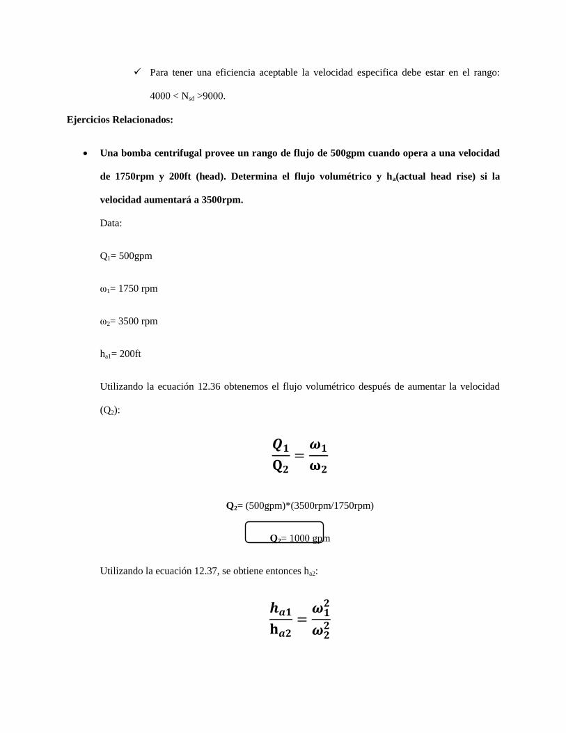
Utilizando la ecuación 12.36 obtenemos el flujo volumétrico después de aumentar la velocidad
(Q2):
Q2= (500gpm)*(3500rpm/1750rpm)
Q2= 1000 gpm
Utilizando la ecuación 12.37, se obtiene entonces ha2:
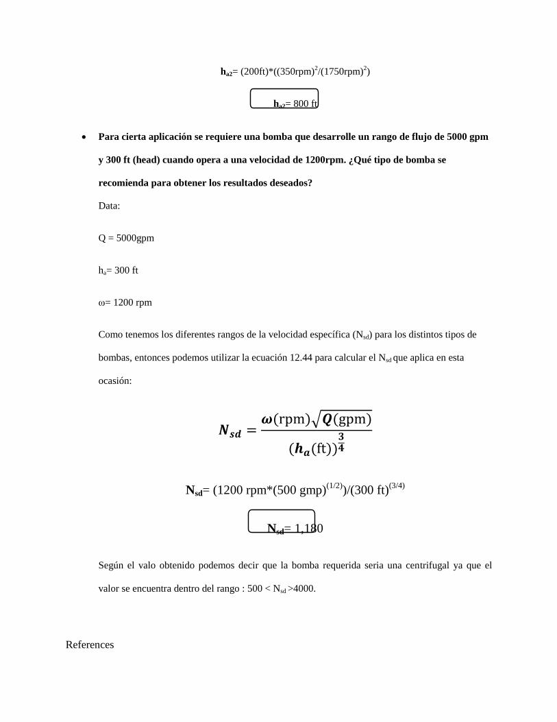
ha2= (200ft)*((350rpm)2/(1750rpm)
2)
ha2= 800 ft
Para cierta aplicación se requiere una bomba que desarrolle un rango de flujo de 5000 gpm
y 300 ft (head) cuando opera a una velocidad de 1200rpm. ¿Qué tipo de bomba se
recomienda para obtener los resultados deseados?
Data:
Q = 5000gpm
ha= 300 ft
ω= 1200 rpm
Como tenemos los diferentes rangos de la velocidad específica (Nsd) para los distintos tipos de
bombas, entonces podemos utilizar la ecuación 12.44 para calcular el Nsd que aplica en esta
ocasión:
( )√ ( )
( ( ))
Nsd= (1200 rpm*(500 gmp)(1/2)
)/(300 ft)(3/4)
Nsd= 1,180
Según el valo obtenido podemos decir que la bomba requerida seria una centrifugal ya que el
valor se encuentra dentro del rango : 500 < Nsd >4000.
References
http://es.wikipedia.org/wiki/Motor_t%C3%A9rmico
http://materias.fi.uba.ar/6720/unidad5c.PDF
http://translate.google.com.pr/translate?hl=es&langpair=en%7Ces&u=http://uspowerpart
ners.org/Topics/SECTION1Topic-TurbineEfficiency.htm
Munson, Bruce, R., Young, Donald, F., Okiishi, Theodore, H. Fundamentals of Fluid
Mechanics, Fifth Edition, p. 693-706.
http://www.monografias.com/trabajos36/bombas-centrifugas/bombas-centrifugas2.shtml
http://es.wikipedia.org/wiki/Bomba_centr%C3%ADfuga
http://fain.uncoma.edu.ar/La.M.Hi/textos/Maquinas%20hidrualicas/BOMBAS.PDF
http://www.sapiensman.com/ESDictionary/imagenes/bomba%20centrifuga.jpg