chapter 9 vents -...
TRANSCRIPT

CHAPTER 9VENTS
Most people don’t think much about vents when they consider the plumbing intheir home or office, but vents play a vital role in the scheme of sanitary plumb-ing. Many plumbers underestimate the importance of vents. The sizing and instal-lation of vents often cause more confusion than the same tasks applied to drains.This chapter will teach you the role and importance of vents. It will also instructyou in the proper methods of sizing and installing vents.
Whether you are working with simple individual vents or complex islandvents, this chapter will improve your understanding of their installation. Why dowe need vents? Vents perform three easily identified functions. The most obviousfunction of a vent is its capacity to carry sewer gas out of a building and into theopen air. A less obvious but equally important aspect of the vent is its ability toprotect the seal in the trap it serves. The third characteristic of the vent is its abil-ity to enable drains to drain faster and better. Let’s look more closely at each ofthese factors.
TRANSPORTATION OF SEWER GAS
Vents transport sewer gas through a building, without exposing occupants of thebuilding to the gas, to an open air space. Why is this important? Sewer gas cancause health problems. The effect of sewer gas on individuals will vary, but itshould be avoided by all. In addition to health problems caused by sewer gas, ex-plosions are also possible when sewer gas is concentrated in a poorly ventilatedarea. Yes, sewer gas can create an explosion when it is concentrated, confined, andignited. As you can see just from looking at this single purpose of vents, they arean important element of a plumbing system.
9.1
PlumbingCode06_ch09 5/29/06 8:16 AM Page 1
PROTECTING TRAP SEALS
Another job plumbing vents perform is the protection of trap seals. The water sit-ting in a fixture’s trap blocks the path of sewer gas trying to enter the plumbingfixture. Without a trap seal, sewer gas could rise through the drainage pipe and en-ter a building through a plumbing fixture. As mentioned above, this could resultin health problems and the risk of explosion. Good trap seals are essential to san-itary plumbing systems.
Vents protect trap seals. How do they do it? They regulate the atmosphericpressure applied to the seals. It is possible for pressures to rise in unvented trapsto a point where the contents actually expel into the fixture. This is not a commonproblem, but if it occurs, the plumbing fixture could become contaminated.
A more likely problem is when the pressure on a trap seal is reduced to a nearvacuum. When this happens, the water creating the trap seal is sucked out of thetrap and down the drain. Once the water is taken from the trap, there is no trap seal.The trap will remain unsealed until water is replaced in the trap. Without water init, a trap is all but useless. Vents prevent these extreme atmospheric pressurechanges, thus protecting the trap seal.
Air admittance valves must be sized in accordance with the standard for thesize of the vent to which the valve is connected. The design of a vent system canbe created with an approved computer program method. Capacity requirementsfor a vent system must be based on the air capacity requirements of the drainagesystem under a peak load condition.
TINY TORNADOS
Have you ever drained your sink or bathtub and watched the tiny water tornados?When you see the fast swirling action of water being pulled down a drain, it usu-ally indicates that the drain is well vented. If water is sluggish and moves out ofthe fixture like a lazy river, the vent for the fixture, if there is one, is not perform-ing at its best.
! CodealertStack-type air admittance valves need to conform to ASSE 1050. Individualand branch-type air admittance valves must conform to ASSE 1051.
9.2 2006 INTERNATIONAL PLUMBING CODES HANDBOOK
FastfactGood trap seals are essential to sanitary plumbing systems.
PlumbingCode06_ch09 5/29/06 8:16 AM Page 2

VENTS 9.3
FIG
UR
E 9
.1S
elf-
siph
onin
g ph
enom
enon
. C
opyr
ight
200
2, I
nter
nati
onal
Cod
e C
ounc
il,
Inc.
, F
alls
Chu
rch,
Vir
gini
a. R
epro
duce
d w
ith
perm
issi
on. A
ll r
ight
s re
serv
ed.
PlumbingCode06_ch09 5/29/06 8:16 AM Page 3

Vents help fixtures to drain faster. The air allowed from the vent keeps the wa-ter moving at a more rapid pace. This not only entertains us with tiny tornados, butit aids in the prevention of clogged pipes. It is possible for drains to drain tooquickly, removing the liquids and leaving hair, grease, and other potential pipeblockers present. However, if a pipe is properly graded and does not contain ex-treme vertical drops into improper fittings, such problems should not occur.
DO ALL PLUMBING FIXTURES HAVE VENTS?
Most local plumbing codes require all fixture traps to be vented, but there are ex-ceptions. In some jurisdictions, combination waste and vent systems are used. Ina combination waste and vent system, vertical vents are rare. Instead of verticalvents, larger drainage pipes are used. The larger diameter of the drain allows airto circulate in the pipe, eliminating the need for a vent as far as satisfactorydrainage is concerned. I have worked with both types of systems, predominantlyvented systems, and in my opinion, vented systems perform much better thancombination waste and vent systems.
Combination waste and vent systems do not have vents on each fixture, sohow is the trap seal protected? Trap seals in a combination system are protectedthrough the use of antisiphon or drum traps. Vented systems normally use P-traps.By using an antisiphon or drum, the trap is not susceptible to backsiphonage.Since these traps are larger, deeper, and made so that the water is not replaced with
9.4 2006 INTERNATIONAL PLUMBING CODES HANDBOOK
TradetipVents protect trap seals. How do they do it? They regulate the atmosphericpressure applied to the seals.
TradetipVents help fixtures to drain faster. The air allowed by the vent keeps the wa-ter moving at a more rapid pace.
?Did you knowWithout water in it, a trap is all but useless.
PlumbingCode06_ch09 5/29/06 8:16 AM Page 4

each use of the fixture, they are not required to be vented, subject to local code re-quirements. Most jurisdictions prohibit the use of drum traps and require traps tobe vented. Before you install your plumbing, check with the local code officer forthe facts pertinent to your location. Fittings for vent piping must be compatiblewith the piping used.
A combination drain and vent system can serve only the following types offixtures:
• Floor drains
• Sinks
VENTS 9.5
?Did you knowCombination waste and vent systems do not have vents on each fixture. Sohow is the trap seal protected? Trap seals in a combination system are pro-tected through the use of antisiphon or drum traps.
FIGURE 9.2 Combination drain and vent system. Copyright 2002, International CodeCouncil, Inc., Falls Church, Virginia. Reproduced with permission. All rights reserved.
• Lavatories
• Drinking fountains
PlumbingCode06_ch09 5/29/06 8:16 AM Page 5

9.6 2006 INTERNATIONAL PLUMBING CODES HANDBOOK
FIGURE 9.3 Combination drain and vent system. Copyright 2002, International CodeCouncil, Inc., Falls Church, Virginia. Reproduced with permission. All rights reserved.
PlumbingCode06_ch09 5/29/06 8:16 AM Page 6

Combination waste and vent systems are not allowed with garbage disposers.The only vertical pipe of a combination drain and vent system is the connectionbetween the fixture drain of a sink, lavatory, or drinking fountain and the horizon-tal combination drain and vent pipe. The maximum vertical distance is 8 feet.
INDIVIDUAL VENTS
Individual vents are, as the name implies, vents that serve individual fixtures.These vents only vent one fixture, but they may connect into another vent that will
VENTS 9.7
FastfactCombination waste and vent systems are not allowed with garbage disposers.
FIGURE 9.4 Individual vent.
PlumbingCode06_ch09 5/29/06 8:16 AM Page 7

extend to the open air. Individual vents do not have to extend from the fixture be-ing served to the outside air without joining another part of the venting system, butthey must eventually vent to open air space.
Sizing an individual vent is easy. The vent must be at least one-half the size ofthe drain it serves, but it may not have a diameter of less than 1.25 inches. For ex-ample, a vent for a 3-inch drain could, in most cases, have a diameter of 1.5 inches.A vent for a 1.5-inch drain may not have a diameter of less than 1.25 inches.
9.8 2006 INTERNATIONAL PLUMBING CODES HANDBOOK
TradetipRelief vents are used in conjunction with other vents. Their purpose is to pro-vide additional air to the drainage system when the primary vent is too farfrom the fixture.
FIGURE 9.5 Relief vent.
PlumbingCode06_ch09 5/29/06 8:16 AM Page 8

RELIEF VENTS
Relief vents are used in conjunction with other vents. Their purpose is to pro-vide additional air to the drainage system when the primary vent is too far fromthe fixture. Relief vents must be at least one-half the size of the pipes they areventing. For example, if a relief vent is venting a 3-inch pipe, the relief ventmust have a 1.5-inch or larger diameter. Use the sizing tables in your local code-book to establish minimum size requirements. Relief vents may be used to ventmore than one fixture.
When relief vents are required on stacks of more than ten branch intervals, thelower end of each relief vent must connect to the soil or waste stack through a wyebelow the horizontal branch serving the floor, and the upper end must connect tothe vent stack through a wye not less than 3 feet above the floor.
CIRCUIT VENTS
Circuit vents are used with a battery of plumbing fixtures. Circuit vents are nor-mally installed just before the last fixture of the battery. Then, the circuit vent isextended upward to the open air or tied into another vent that extends to the out-side. Circuit vents may tie into stack vents or vent stacks. When sizing a circuitvent, you must account for its developed length. But in any event, the diameter ofa circuit vent must be at least one-half the size of the drain it is serving.
VENT SIZING USING DEVELOPED LENGTH
What effect does the length of the vent have on the vent’s size? The developedlength, the total linear footage of pipe making up the vent, is used in conjunctionwith factors provided in codebooks to determine vent sizes. To size circuit vents,
VENTS 9.9
FastfactRelief vents must be at least one-half the size of the pipes they are venting.
?Did you knowCircuit vents may tie into stack vents or vent stacks.
PlumbingCode06_ch09 5/29/06 8:16 AM Page 9

branch vents, and individual vents for horizontal drains, you must use this methodof sizing.
The criteria needed for sizing a vent, based on developed length, are: the gradeof the drainage pipe, the size of the drainage pipe, the developed length of the vent,and the factors allowed by local code requirements. Knowing this information,you will use the sizing tables in your local codebook to establish pipe sizing.
9.10 2006 INTERNATIONAL PLUMBING CODES HANDBOOK
FIGURE 9.6 Circuit-vented branch with additional fixture connections. Copyright 2002,International Code Council, Inc., Falls Church, Virginia. Reproduced with permission. Allrights reserved.
PlumbingCode06_ch09 5/29/06 8:16 AM Page 10

VENTS 9.11
FIGURE 9.7 Circuit venting. Copyright 2002, International CodeCouncil, Inc., Falls Church, Virginia. Reproduced with permission.All rights reserved.
PlumbingCode06_ch09 5/29/06 8:16 AM Page 11

BRANCH VENTS
Branch vents are vents extending horizontally and connecting multiple vents to-gether. Branch vents are sized with the developed-length method. A branch or in-dividual vent that is the same size as the drain it serves is unlimited in the devel-oped length it may reach. A branch vent that has a developed length in excess of40 feet must increase the pipe sizing by one nominal size for the entire developedlength of the vent.
9.12 2006 INTERNATIONAL PLUMBING CODES HANDBOOK
FastfactA branch vent that has a developed length in excess of 40 feet must in-crease the pipe sizing by one nominal size for the entire developed lengthof the vent.
FIGURE 9.8 Branch vent.
PlumbingCode06_ch09 5/29/06 8:16 AM Page 12

VENTS 9.13
FIGURE 9.9 Vent stack.
� Pro pointerBe advised, not all local codes use the same sizing charts, so check your localcode before you trust your sizing.
VENT STACKS
A vent stack is a pipe used only for the purpose of venting. Vent stacks extend up-ward from the drainage piping to the open air outside a building. Vent stacks areused as connection points for other vents, such as branch vents. A vent stack is aprimary vent that accepts the connection of other vents and vents an entire system.Vent stacks run vertically and are sized a little differently.
PlumbingCode06_ch09 5/29/06 8:16 AM Page 13

9.14 2006 INTERNATIONAL PLUMBING CODES HANDBOOK
TA
BL
E 9
.1S
ize
and
deve
lope
d le
ngth
of
stac
k ve
nts
and
vent
sta
cks.
Cop
yrig
ht 2
006,
Int
erna
tion
al C
ode
Cou
ncil
, Inc
.,F
alls
Chu
rch,
Vir
gini
a. R
epro
duce
d w
ith
perm
issi
on. A
ll r
ight
s re
serv
ed.
PlumbingCode06_ch09 5/29/06 8:16 AM Page 14

VENTS 9.15
PlumbingCode06_ch09 5/29/06 8:16 AM Page 15

The basic procedure for sizing a vent stack is similar to that used with branchvents, but there are some differences. You must know the size of the soil stack, thenumber of fixture units carried by the soil stack, and the developed length of thevent stack. With this information and the regulations of your local plumbing code,you can size your vent stack. The same sizing method is used when computing thesize of stack vents.
STACK VENTS
Stack vents are really two pipes in one. The lower portion of the pipe is a soil pipe,and the upper portion is a vent. This is the type of primary vent most often foundin residential plumbing. Stack vents are sized with the same methods used for ventstacks. Offsets are permitted in the stack vent and must be located at least 6 inchesabove the flood level of the highest fixture.
9.16 2006 INTERNATIONAL PLUMBING CODES HANDBOOK
FIGURE 9.10 Stack vent.
PlumbingCode06_ch09 5/29/06 8:16 AM Page 16

COMMON VENTS
Common vents are single vents that vent multiple traps. Common vents are only al-lowed when the fixtures being served by the single vent are on the same floor level.Some jurisdictions require the drainage of fixtures being vented with a commonvent to enter the drainage system at the same level. Normally, not more than two
VENTS 9.17
FIGURE 9.11 Common vent.
FastfactOffsets are permitted in the stack vent and must be located at least 6 inchesabove the flood level of the highest fixture.
PlumbingCode06_ch09 5/29/06 8:16 AM Page 17

traps can share a common vent, but there is an exception in some regions. In someareas you may vent the traps of up to three lavatories with a single common vent.Common vents are sized with the same technique applied to individual vents.
ISLAND VENTS
Island vents are unusual looking vents. They are allowed for sinks and lavatories.The primary use for these vents is with the trap of a kitchen sink when the sink isplaced in an island cabinet. The vent must rise as high as possible under the cabi-net before it takes a U-turn and heads back downward. Since this piping does notrise above the flood-level rim of the fixture, it must be considered a drain. Fittingsapproved for drainage must be used in making an island vent. The vent portion ofan island vent must be equipped with a clean-out. The vent may not tie into a reg-ular vent until it rises at least 6 inches above the flood-level rim of the fixture.
WET VENTS
Wet vents are pipes that serve as a vent for one fixture and a drain for another.Only the fixtures within a bathroom group may connect to a wet-vented horizon-tal branch drain. Additional fixtures must discharge downstream of the wet vent.Wet vents, once you know how to use them, can save you a lot of money and time.
9.18 2006 INTERNATIONAL PLUMBING CODES HANDBOOK
TABLE 9.2 Common vent sizes. Copyright 2006, InternationalCode Council, Inc., Falls Church, Virginia. Reproduced withpermission. All rights reserved.
TradetipNormally, not more than two traps can share a common vent, but there is anexception in some regions. In some areas you may vent the traps of up tothree lavatories with a single common vent.
PlumbingCode06_ch09 5/29/06 8:16 AM Page 18

By effectively using wet vents, you can reduce the amount of pipe, fittings, and la-bor required to vent a bathroom group or two. Dry vents connected to wet ventsmust be sized based on the largest required diameter of pipe within the wet ventsystem served by the dry vent.
Any combination of fixtures within two bathroom groups located on the samefloor level can be vented by a vertical wet vent. This type of vent is required to ex-tend from the connection to the dry vent down to the lowest fixture drain connec-tion. Each fixture is required to connect independently to the vertical wet vent.When water closets are connected to this type of system, the connections must be
VENTS 9.19
FIGURE 9.12 Island fixture vent. Copyright 2002, International Code Council, Inc.,Falls Church, Virginia. Reproduced with permission. All rights reserved.
TradetipIsland vents are allowed for sinks and lavatories.
TradetipBy effectively using wet vents, you can reduce the amount of pipe, fittings,and labor required to vent a bathroom group or two.
PlumbingCode06_ch09 5/29/06 8:16 AM Page 19

made at the same elevation. Fixtures other than water closets are to connect to thesystem either at the same level as the water closets or above those connections.The dry vent connection to the vertical wet vent has to be an individual or com-mon vent serving one or two fixtures.
The sizing of wet vents is based on fixture-units. The size of the pipe is deter-mined by how many fixture-units it may be required to carry. A 3-inch wet ventcan handle twelve fixture-units. A 2-inch wet vent is rated for four fixture-units,and a 1.5-inch wet vent is allowed only one fixture-unit. It is acceptable to wetvent two bathroom groups, six fixtures, with a single vent, but the bathroomgroups must be on the same floor level.
Depending upon local regulations, the horizontal branch connecting to thedrainage stack may have to enter at a level equal to or below the water-closetdrain. However, the branch may connect to the drainage at the closet bend. When
9.20 2006 INTERNATIONAL PLUMBING CODES HANDBOOK
TradetipThe sizing of wet vents is based on fixture-units.
FIGURE 9.13 Wet venting. Copyright 2002, International Code Council, Inc., FallsChurch, Virginia. Reproduced with permission. All rights reserved.
PlumbingCode06_ch09 5/29/06 8:16 AM Page 20

wet-venting two bathroom groups, the wet vent must have a minimum diameter of2 inches. Kitchen sinks and washing machines may not be drained into a 2-inchcombination waste and vent. Water closets and urinals are restricted to verticalcombination waste and vent systems.
Water closets that are not located on the highest floor must be back-vented. If,however, the wet vent is connected directly to the closet bend with a 45-degree
VENTS 9.21
FIGURE 9.14 Double bathroom group (private) wet vent. Copyright2002, International Code Council, Inc., Falls Church, Virginia.Reproduced with permission. All rights reserved.
PlumbingCode06_ch09 5/29/06 8:16 AM Page 21

bend, the toilet being connected is not required to be back vented even if it is on alower floor.
Wet venting in some regions may be limited to vertical piping. These verticalpipes are restricted to receiving the waste from fixtures that have fixture-unit rat-ings of two or less and that serve to vent no more than four fixtures. Wet ventsmust be one pipe-size larger than normally required, but they must never besmaller than 2 inches in diameter.
CROWN VENTS
A crown vent is a vent that extends upward from a trap or trap arm. Crown-ventedtraps are not allowed. When crown vents are used, they are normally used on traparms, but even then they are not common. The vent must be on the trap arm, andit must be behind the trap by a distance equal to twice the pipe size. For example,on a 1.5-inch trap, the crown vent would have to be 3 inches behind the trap on thetrap arm.
VENTS FOR SUMPS AND SEWER PUMPS
When sumps and sewer pumps are used to store and remove sanitary waste, thesump must be vented. If you will be installing a pneumatic sewer ejector, you willneed to run the sump vent to outside air without tying it into the venting systemfor a standard sanitary plumbing system. If your sump will be equipped with a reg-ular sewer pump, you may tie the vent from the sump back into the main ventingsystem for the other sanitary plumbing.
9.22 2006 INTERNATIONAL PLUMBING CODES HANDBOOK
TradetipIf wet venting is allowed on different floor levels in your region, the ventsmust have at least a 2-inch diameter.
FastfactIf you will be installing a pneumatic sewer ejector, you will need to run thesump vent to outside air without tying it into the venting system for a stan-dard sanitary plumbing system.
PlumbingCode06_ch09 5/29/06 8:16 AM Page 22

Additional rulings apply in some regions. You may find that sump vents mustnot be smaller than 1.25-inch pipe. The size requirements for sump vents are de-termined by the discharge of the pump. For example, a sewer pump capable ofproducing 20 gallons a minute could have its sump vented for an unlimited dis-tance with a 1.5-inch pipe. If the pump was capable of producing 60 gallons perminute, a 1.5-inch pipe could not have a developed length of more than 75 feet.
In most cases, a 2-inch vent is used on sumps, and the distance allowed fordeveloped length is not a problem. However, if your pump will pump more than
VENTS 9.23
FIGURE 9.15 Multifloor wet venting. Copyright 2002, International Code Council,Inc., Falls Church, Virginia. Reproduced with permission. All rights reserved.
PlumbingCode06_ch09 5/29/06 8:16 AM Page 23
9.24 2006 INTERNATIONAL PLUMBING CODES HANDBOOK
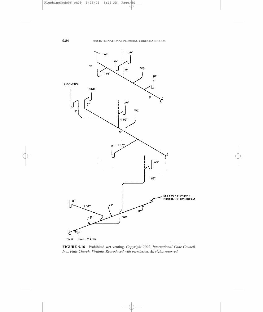
FIGURE 9.16 Prohibited wet venting. Copyright 2002, International Code Council,Inc., Falls Church, Virginia. Reproduced with permission. All rights reserved.
PlumbingCode06_ch09 5/29/06 8:16 AM Page 24

VENTS 9.25
TABLE 9.3 Wet vent size. Copyright 2006, International CodeCouncil, Inc., Falls Church, Virginia. Reproduced with permission.All rights reserved.
FIGURE 9.17 Crown venting. Copyright 2002, International CodeCouncil, Inc., Falls Church, Virginia. Reproduced with permission. Allrights reserved.
PlumbingCode06_ch09 5/29/06 8:16 AM Page 25

100 gallons per minute, you had better take the time to do some math. Your code-book will provide you with the factors you need to size your vent, and the sizingis easy. You simply look for the maximum discharge capacity of your pump andmatch it with a vent that allows the developed length you need. This concludes thegeneral description and sizing techniques for various vents. Next we are going tolook at regulations dealing with the installation methods for vents.
VENT-INSTALLATION REQUIREMENTS
Since there are so many types of vents and their role in the plumbing system is soimportant, there are many regulations affecting their installation. What follows arespecifics for installing various vents.
Any building equipped with plumbing must also be equipped with a mainvent. The size of this vent must be no less than one-half the size of the buildingdrain. This vent must run undiminished in size and as directly as possible fromthe building drain through to the open air or to a vent header that extends to theopen air. Any plumbing system that receives the discharge from a water closetmust have either a main vent stack or stack vent. This vent must originate at a3-inch drainage pipe and extended upward until it penetrates the roof of thebuilding and meets outside air. The vent size requirements call for a minimumdiameter of 3 inches. However, some codes allow the main stack in detachedbuildings, where the only plumbing is a washing machine or laundry tub, to havea diameter of 1.5 inches.
Main vents that are vent stacks must connect to building drains or to the basesof drainage stacks in compliance with the plumbing code. A main vent that is astack vent must be an extension of the drainage stack. When a vent stack connectsto a building drain, the connection is to be located downstream of the drainagestack and within a distance of ten times the diameter of the drainage stack.
9.26 2006 INTERNATIONAL PLUMBING CODES HANDBOOK
FastfactAny building equipped with plumbing must also be equipped with a mainvent. The size of this vent must be no less than one-half the size of the build-ing drain.
?Did you knowAny building equipped with plumbing must also be equipped with a mainvent.
PlumbingCode06_ch09 5/29/06 8:16 AM Page 26

VENTS 9.27
TA
BL
E 9
.4S
ize
and
leng
th o
f su
mp
vent
s. C
opyr
ight
200
6, I
nter
nati
onal
Cod
e C
ounc
il, I
nc.,
Fal
ls C
hurc
h,V
irgi
nia.
Rep
rodu
ced
wit
h pe
rmis
sion
. All
rig
hts
rese
rved
.
PlumbingCode06_ch09 5/29/06 8:16 AM Page 27

9.28 2006 INTERNATIONAL PLUMBING CODES HANDBOOK
TA
BL
E 9
.5M
inim
um d
iam
eter
and
max
imum
len
gth
of i
ndiv
idua
l br
anch
fix
ture
ven
ts a
nd i
ndiv
idua
l fi
xtur
e he
ader
vent
s fo
r sm
ooth
pip
es. C
opyr
ight
200
6, I
nter
nati
onal
Cod
e C
ounc
il, I
nc.,
Fal
ls C
hurc
h, V
irgi
nia.
Rep
rodu
ced
wit
hpe
rmis
sion
. All
rig
hts
rese
rved
.
PlumbingCode06_ch09 5/29/06 8:16 AM Page 28

Multiple branch vents that exceed 40 feet in developed length must be in-creased by one nominal size for the entire developed length of the vent pipe. Whena vent penetrates a roof, it must be flashed or sealed to prevent water from leak-ing past the pipe and through the roof. Metal flashings with rubber collars are nor-mally used for flashing vents, but more modern flashings are made from plasticrather than metal.
The vent must extend above the roof to a certain height. The height may fluc-tuate among geographical locations. Average vent extensions are between 12 and24 inches, but check with your local regulations to determine the minimum heightin your area.
VENTS 9.29
TABLE 9.6 Maximum distance of fixture trap from vent.Copyright 2006, International Code Council, Inc., Falls Church,Virginia. Reproduced with permission. All rights reserved.
TABLE 9.7 Waste stack vent size. Copyright 2006, InternationalCode Council, Inc., Falls Church, Virginia. Reproduced withpermission. All rights reserved.
PlumbingCode06_ch09 5/29/06 8:16 AM Page 29

When vents terminate in the open air, the proximity of their location to win-dows, doors, or other ventilating openings must be considered. If a vent wereplaced too close to a window, sewer gas might be drawn into the building whenthe window was open. Vents should be kept 10 feet from any window, door, open-ing, or ventilation device. If the vent cannot be kept at least 10 feet from the open-ing, the vent should extend at least 2 feet above the opening. Depending upon yourlocal region, the vent may be required to extend at least 3 feet above the opening.
When sidewall vents are installed, they must be protected against birds and ro-dents with a wire mesh or similar cover. Sidewall vents must not extend closerthan 10 feet to the property boundary of the building lot. If the building isequipped with soffit vents, sidewall vents may not be used in such a way that theyterminate under the soffit vents. This rule is in effect to prevent sewer gas frombeing sucked into the attic of the home.
9.30 2006 INTERNATIONAL PLUMBING CODES HANDBOOK
� Pro pointerIf a roof being penetrated by a vent is used for activities other than weatherprotection, such as a patio, the vent must extend several feet above the roof.Some regions require the vent to extend at least 5 feet above the roof. Otherregions require the extension to rise even higher.
TradetipIn cold climates, vents must be protected from freezing. Condensation cancollect on the inside of vent pipes. In cold climates this condensation mayturn to ice. As the ice mass grows, the vent becomes blocked and useless.This type of protection is usually accomplished by increasing the size of thevent pipe. This ruling normally applies only in areas where temperatures areexpected to be below 0 degrees F. Some codes require vents in this categoryto have a minimum diameter of 3 inches. If this requires an increase in pipesize, the increase must be made at least 1 foot below the roof. In the case ofsidewall vents, the change must be made at least 1 foot inside the wall. Insome regions, all vents must have diameters of at least 2 inches but never lessthan the normally required vent size. Anny change in pipe size must takeplace at least 12 inches before the vent penetrates into open air, and the ventmust extend to a height of 10 inches.
There may be occasions when it is better to terminate a plumbing vent outthe side of a wall rather than through a roof. Some jurisdictions don’t allowthis practice, but others do. Some regions prohibit sidewall vents from ter-minating under any building’s overhang.
PlumbingCode06_ch09 5/29/06 8:16 AM Page 30

VENTS 9.31
FIGURE 9.18 Branch interval detail.
PlumbingCode06_ch09 5/29/06 8:16 AM Page 31

Some codes require buildings that have soil stacks with more than five branchintervals to be equipped with a vent stack. Others require a vent stack with build-ings that have at least ten stories above the building drain. The vent stack will nor-mally run up near the soil stack. The vent stack must connect into the buildingdrain at or below the lowest branch interval. The vent stack must be sized accord-ing to tables in your local codebook. The vent stack may be required to be con-nected within ten times its pipe size on the downward side of the soil stack. Thismeans that a 3-inch vent stack must be within 30 inches of the soil stack on thedownward side of the building drain.
Check your local code to see if stack vents must be connected to the drainagestack at intervals of every five stories. If so, the connection must be made with arelief yoke vent. The yoke vent must be at least as large as either the vent stack or
9.32 2006 INTERNATIONAL PLUMBING CODES HANDBOOK
FIGURE 9.19 Yoke vent.
PlumbingCode06_ch09 5/29/06 8:16 AM Page 32

soil stack, whichever is smaller. This connection must be made with a wye fittingat least 42 inches off the floor.
In large plumbing jobs where there are numerous branch intervals, it may benecessary to vent offsets in the soil stack. Normally, the offset must be more than45 degrees to warrant an offset vent. It is common for offset vents to be requiredwhen the soil stack offsets have five or more branch intervals above them.
Dry vents must be installed in a manner to prevent clogging and blockages.You may not lay a fitting on its side and use a quarter bend to turn the vent up ver-tically. Dry vents should leave the drainage pipe in a vertical position. An easyway to remember this is that if you need an elbow to get the vent up from thedrainage, you are doing it wrong.
Most vents can be tied into other vents, such as a vent stack or stack vent. Butthe connection for the tie-in must be at least 6 inches above the flood-level rim ofthe highest fixture served by the vent.
Some regions allow the use of circuit vents to vent fixtures in a battery. Thedrain serving the battery must be operating at one-half its fixture-unit rating. If theapplication is on a lower-floor battery with a minimum of three fixtures, reliefvents are required. You must also pay attention to the fixtures draining above theselower-floor batteries.
When a fixture with a fixture rating of four or less and a maximum drain sizeof 2 inches is above the battery, every vertical branch must have a continuous vent.If a fixture with a fixture-unit rating exceeding four is present, all fixtures in thebattery must be individually vented. Circuit-vented batteries may not receive thedrainage from fixtures on a higher level.
Circuit vents should rise vertically from the drainage. However, the vent canbe taken off the drainage horizontally if the vent is washed by a fixture with a rat-ing of no more than four fixture units. The washing cannot come from a water
VENTS 9.33
FastfactIn large plumbing jobs where there are numerous branch intervals, it may benecessary to vent offsets in the soil stack.
� Pro pointerJust as drains are installed with a downward pitch, vents must also be installedwith a consistent grade. Vents should be graded to allow any water enteringthe vent pipe to drain into the drainage system. A typical grade for vent pip-ing is .25 inch to the foot.
PlumbingCode06_ch09 5/29/06 8:16 AM Page 33

9.34 2006 INTERNATIONAL PLUMBING CODES HANDBOOK
FIGURE 9.20 Vertical rise of vent. Copyright 2002, International Code Council, Inc.,Falls Church, Virginia. Reproduced with permission. All rights reserved.
FastfactMost vents can be tied into other vents, such as a vent stack or stack vent.But the connection for the tie-in must be at least 6 inches above the flood-level rim of the highest fixture served by the vent.
PlumbingCode06_ch09 5/29/06 8:16 AM Page 34

closet. The pipe being washed must be at least as large as the horizontal drainagepipe it is venting.
Circuit vents may at times be used to vent up to eight fixtures utilizing a com-mon horizontal drain. Circuit vents must be dry vents, and they should connect tothe horizontal drain in front of the last fixture on the branch. The horizontal drainbeing circuit-vented must not have a grade of more than 1 inch per foot. Somecode requirements interpret the horizontal section of drainage being circuit-ventedas a vent. If a circuit vent is venting a drain with more than four water closets at-tached to it, a relief vent must be installed in conjunction with the circuit vent.
VENTS 9.35
FIGURE 9.21 Improperly connected vent serving a drain. Copyright 2002, InternationalCode Council, Inc., Falls Church, Virginia, Reproduced with permission. All rights re-served.
TradetipCircuit vents may at times be used to vent up to eight fixtures utilizing acommon horizontal drain.
PlumbingCode06_ch09 5/29/06 8:16 AM Page 35

Vent placement in relation to the trap it serves is important and regulated. Themaximum allowable distance between a trap and its vent will depend on the sizeof the fixture drain and trap.
All vents, except those for fixtures with integral traps, should connect abovethe trap seal. A sanitary tee fitting should be used when going from a vertical stackvent to a trap. Other fittings with a longer turn, such as a combination-wye-and-eighth bend, will place the trap in more danger of backsiphonage. I know that thisgoes against the common sense of a smoother flow of water, but the sanitary teereduces the risk of a vacuum.
All individual, branch, and circuit vents are required to connect to a vent stack,stack vent, or air admittance valve or to extend to open air. Vents for future-userough-ins must be not less than one-half the size of the drain to be served. Rough-in vents must be labeled as vents and must either be connected to the vent systemor extend to open air.
SUPPORTING YOUR PIPE
Vent pipes must be supported. Vents may not be used to support antennas, flag-poles, and similar items. Depending upon the type of material you are using andwhether the pipe is installed horizontally or vertically, the spacing between
9.36 2006 INTERNATIONAL PLUMBING CODES HANDBOOK
FIGURE 9.22 Circuit vent with relief vent.
PlumbingCode06_ch09 5/29/06 8:16 AM Page 36
hangers will vary. Both horizontal and vertical pipes require support. The regu-lations in the plumbing code apply to the maximum distance between hangers.
Some interceptors, such as those used as a settling tank that discharges througha horizontal indirect-waste, are not required to be vented in certain regions.However, the interceptor receiving the discharge from the unvented interceptormust be properly vented and trapped.
Traps for sinks that are a part of a piece of equipment, such as a soda fountain,are not required to be vented when venting is impossible. But, these drains mustdrain through an indirect waste to an approved receptor.
Depending upon your region, you may find that all soil stacks that receive thewaste of at least two vented branches must be equipped with a stack vent or a mainstack vent. Except when approved, fixture drainage may not be allowed to enter astack at a point above a vent connection. Side-inlet closet-bends are allowed toconnect to fixtures that are vented. However, these connections may not be usedto vent a bathroom, unless the connection is washed by a fixture. All fixturesdumping into a stack below a higher fixture must be vented, except when specialapproval is granted for a variance. Stack vents and vent stacks must connect to acommon vent header prior to vent termination.
Up to two fixtures, set back-to-back or side-by-side, within the allowable dis-tance between the traps and their vents may be connected to a common horizon-tal branch that is vented by a common vertical vent. However, the horizontalbranch must be one pipe size larger than normal. When applying this rule, the fol-lowing ratings apply: shower drains, 3-inch floor drains, 4-inch floor drains,pedestal urinals, and water closets with fixture-unit ratings of four are consideredto have 3-inch drains.
Some fixture groups are allowed to be stack vented without individual backvents. These fixture groups must be located in one-story buildings or on the topfloor of the building, with some special provisions. Fixtures located on the topfloor must connect independently to the soil stack, and the bathing units and wa-ter closets must enter the stack at the same level.
This same stack venting procedure can be adapted to work with fixtures onlower floors. The stack being stack vented must enter the main soil stack thougha vertical eighth-bend and wye combination. The drainage must enter above theeighth-bend. A 2-inch vent must be installed on the fixture group. This vent mustbe 6 inches above the flood-level rim of the highest fixture in the group.
Some fixtures can be served by a horizontal waste that is within a certain dis-tance of a vent. When piped in this manner, bathtubs and showers are both re-quired to have 2-inch P-traps. These drains must run with a minimum grade of
VENTS 9.37
?Did you knowVents may not be used to support antennas, flagpoles, and similar items.
PlumbingCode06_ch09 5/29/06 8:16 AM Page 37

1.25 inches per foot. A single drinking fountain can be rated as a lavatory for thistype of piping. With this type of system, fixture drains for lavatories may not ex-ceed 1.25 inches, and sink drains cannot be larger than 1.5 inches in diameter.
In multistory situations, it is possible to drain up to three fixtures into a soilstack above the highest water closet or bathtub connection without reventing. Todo this, certain requirements must be met. These requirements are as follows:
• Minimum stack size of 3 inches is required.
• Approved fixture-unit load on stack is met.
• All lower fixtures must be properly vented.
• All individually unvented fixtures are within allowable distances to the mainvent.
• Fixture openings shall not exceed the size of their traps.
• All code requirements must be met and approved.
WORKING WITH A COMBINATION WASTE AND VENT SYSTEM
Most jurisdictions limit the types of fixtures can that be served by combinationwaste and vent systems, but not all. In many locations, it is a code violation to in-clude a toilet on a combination system, but Maine, for example, will allow toiletswith this type of system. Since combination systems can get you into a sticky sit-uation, you should consult your local code officer before using them. I will, how-ever, explain how this system works in general.
The type of fixtures you are allowed to connect to in a combination waste andvent system may be limited. In some areas, the only fixtures allowed on the com-bination system are: floor drains, standpipes, sinks, and lavatories. Other areaswill allow showers, bathtubs, and even toilets to be installed with the combo sys-tem. You will have to check your local regulations to see how they affect yourchoices of plumbing systems.
Combination waste and vent systems are comprised mainly of horizontal pip-ing. Generally, the only vertical pipes are the risers to lavatories, sinks, and stand-pipes. These pipes may not normally exceed 8 feet in length. This type of systemrelies on an oversized drainpipe to provide air circulation for drainage. The pipeis often required to be twice the size required for a drain vented normally. Thecombination system typically must have at least one vent. The vent should con-nect to a horizontal drainpipe.
A dry vent is required to be connected at any point within the system, or thesystem can connect to a horizontal drain that is vented according to the plumbingcode. Combination drain and vent systems connecting to building drains receiv-ing only the discharge from a stack or stacks must be provided with a dry vent.The vent connection to the combo system must extend at least 6 inches verticallyabove the flood level rim of the highest fixture being vented before offsettinghorizontally.
9.38 2006 INTERNATIONAL PLUMBING CODES HANDBOOK
PlumbingCode06_ch09 5/29/06 8:16 AM Page 38

Any vertical vent must rise to a point at least 6 inches above the highest fix-ture being served before it may take a horizontal turn. In a combination system thepipes are rated for fewer fixture-units. A 3-inch pipe connecting to a branch orstack may only be allowed to carry twelve fixture-units. A 4-inch pipe, under thesame conditions, could be restricted to twenty fixture-units. Similarly, a 2-inchpipe might only handle three fixture-units, and a 1.5-inch pipe may not be allowed.The ratings for these pipes can increase when the pipes are connecting to a build-ing drain.
Stack vents are allowed, but not always in the normal way. All fixtures on acombo system may be required to enter the stack vent individually, as opposed toon a branch, as would normally be the case. A stack vent used in a combo systemgenerally must be a straight vertical vent without offsets. The stack vent usuallycannot even be offset vertically; it simply cannot be offset. This rule is differentin some locations, so check with your local plumbing inspector to see if you areaffected by the no-offset rule.
Since stack vents are common and often required in a combination system,you must know how to size these pipes. The sizing is generally done based on thenumber of fixture units entering the stack. I will give you an example of how astack vent for a combo system might be sized.
Since not all pipes run in conjunction with a combination waste and vent sys-tem have to follow the combo rules, it is possible that you would have a 1.5-inchpipe entering a stack. The 1.5-inch pipe could only be used if it had an individualvent. It is also possible that the stack vent would be a 1.5-inch pipe.
First, let’s look at the maximum number of fixture units (fu) allowed on astack:
• 1.5-inch stack = 2 fu
• 2-inch stack = 4 fu
• 3-inch stack = 24 fu
• 4-inch stack = 50 fu
• 5-inch stack = 75 fu
• 6-inch stack = 100 fu
When you are concerned with the size of a drain dumping into the stack, thereare only two pipe sizes to contend with. All pipe sizes larger than 2 inches maydump an unlimited number of fixture units into the stack. A 1.5-inch pipe may runone fixture unit into the stack, and a 2-inch pipe may deliver two fixture units.Sizing your stack is as simple as finding your fixture-unit load on the chart in yourlocal codebook. Compare your fixture units to the chart and select a pipe size ratedfor that load.
Again, I want to remind you that combination waste and vent systems vary agreat deal, so confirm your local requirements before using this type of system.
VENTS 9.39
PlumbingCode06_ch09 5/29/06 8:16 AM Page 39

PlumbingCode06_ch09 5/29/06 8:16 AM Page 40