chapter a-4 mechanical index - savannah … standard 90.1-2010 energy standard for buildings except...
TRANSCRIPT

A-4-i
CHAPTER A-4 Revised Aug 2015
MECHANICAL
INDEX 4.1 GENERAL 4.2 APPLICABLE PUBLICATIONS 4.2.1 International Code Council, Inc. 4.2.2 Unified Facilities Criteria (UFC) 4.2.3 Department of the Army Technical Instructions (TI) 4.2.4 Air Force Manuals, Regulations and Instructions 4.2.5 American Society of Mechanical Engineers (ASME) 4.2.6 Air Conditioning, Heating and Refrigeration Institute (AHRI) 4.2.7 American Conference of Governmental Industrial Hygienists (ACGIH) 4.2.8 American Society of Heating, Refrigeration, and Air Conditioning Engineers (ASHRAE) Inc. Standards (Latest Edition)
4.2.9 Sheet Metal and Air Conditioning Contractors' National Association (SMACNA) Inc. (Latest Edition)
4.2.10 National Fire Protection Association (NFPA) Standards (Latest Edition) 4.2.11 Steel Structures Painting Council (SSPC) 4.2.12 Guide Specifications 4.2.13 Engineering Regulations (ER) 4.2.14 American National Standards Institute (ANSI) 4.2.15 Engineer Technical Letters
4.2.16 US DOD Criteria 4.2.17 Energy Criteria
4.3 PRECONCEPT (PROGRAMMING) SUBMITTAL REQUIREMENTS 4.4 CODE 3 DESIGN REQUIREMENTS 4.5 CONCEPT/EARLY PRELIMINARY (35 PERCENT) DESIGN SUBMITTAL REQUIREMENTS 4.5.1 Concept/Early Preliminary Design Analysis 4.5.2 Concept/Early Preliminary Drawings 4.5.3 Concept/Early Preliminary Specifications 4.5.4 Standard Drawings or Site Adaptations 4.5.5 Field Investigation 4.5.6 Boiler Permits 4.6 PRELIMINARY (OVER THE SHOULDER) SUBMITTAL REQUIREMENTS 4.7 PRELIMINARY (60 PERCENT) DESIGN SUBMITTAL REQUIREMENTS 4.7.1 General 4.7.2 Preliminary Design Analysis 4.7.3 Standard Computation Forms 4.7.4 Preliminary Drawings 4.7.5 Preliminary Specifications 4.7.6 Boiler Permits 4.8 FINAL (100 PERCENT) DESIGN SUBMITTAL REQUIREMENTS

A-4-ii
4.8.1 General 4.8.2 Final Design Analysis 4.8.3 Final Drawings 4.8.4 Final Specifications 4.9 CORRECTED FINAL DESIGN SUBMITTAL REQUIREMENTS 4.9.1 Notice 4.9.2 Compliance 4.10 REQUIREMENTS FOR PREPARATION OF DESIGN/BUILD (CONCEPT 30%) RFP PACKAGES 4.10.1 General 4.10.2 Draft RFP Submittal 4.10.3 Final RFP Submittal 4.11 TECHNICAL REQUIREMENTS 4.11.1 Statement of Work 4.11.2 Basic Technical Requirements 4.11.3 Coordination of Work
4.11.4 Supplementary Technical Publications 4.11.5 Guide Specifications 4.11.6 System Selection 4.11.7 Standard Systems Criteria 4.11.8 Boiler Permits 4.11.9 Sustainable Design 4.11.10 Energy Policy Act of 2005 (Public Law 109-58) 4.11.11 Energy Independence and Security Act of 2007 4.11.12 ASHRAE 189.1 4.12 REQUIREMENTS FOR PREPARATION OF MILCON TRANSFORMATION (CONCEPT 15%) MODEL RFP PACKAGES 4.12.1 General 4.12.2 Draft RFP Submittal 4.12.3 Final RFP Submittal EXHIBITS A-4-1 Typical Design Analysis Format for Closed Head Sprinkler System A-4-2 Heating and Air-Conditioning Outside Design Conditions for Savannah District Sites A-4-3 Sample Mechanical Equipment Schedules A-4-4 HVAC System Alternatives A-4-5 Savannah District Certificate for Design of Mechanical Room

A-4-1
CHAPTER A-4
MECHANICAL 4.1 GENERAL. This chapter provides the minimum requirements and guidance for preparation and development of the following design aspects: Heating, ventilating, air conditioning (including chilled water and dual-temperature water distribution systems), plumbing (including compressed air, fuel gas, and medical gas systems), fire suppression systems, central energy plants, and P.O.L. systems. Further guidance for these mechanical systems will be provided in the Specific Instructions, if required. Guidance for other mechanical systems will also be provided in the Specific Instructions. 4.2 APPLICABLE PUBLICATIONS. The most current editions of the publications listed below constitute an addendum to this chapter wherever referenced or applicable. 4.2.1 International Code Council, Inc. ICC IBC International Building Code (Current Edition) ICC IPC International Plumbing Code (Current Edition) ICC IPC International Mechanical Code (Current Edition) 4.2.2 Unified Facilities Criteria (UFC) 1-200-02 High Performance and Sustainable Building Requirements, 01-Mar-13 1-300-07A Technical Requirements: Design-Build, 01-Mar-05 3-310-04 USACE Design: Seismic Design for Buildings, 22-June-07 3-400-01 Energy Conservation, 05-Jul-02 3-400-02 Engineering Weather Data, 28-Feb-03 3-400-02 Design: Engineering Weather Data, 28-Feb-03 3-401-01 Mechanical Engineering, 1 Jul 13 3-410-01FA Heating, Ventilating, and Air Conditioning Systems, 1 Jul 13 3-410-02 Lonworks (R) Direct Digital Control for HVAC and Other Local Building Systems,
1 May 12 3-410-04N Industrial Ventilation, 25 Oct 04 3-420-01 Plumbing Systems, 25-Oct-04 3-420-02FA Compressed Air, 15-May-03 3-430-01FA Heating and Cooling Distribution Systems, 25-Jul-03 3-430-02FA Central Steam Boiler Plants, 15-May-03

A-4-2
3-430-08N Central Heating Plants, 16 Jan 04 3-430-09 Exterior Mechanical Utility Distribution, 16 Jan 04 3-430-11 Boiler Control Systems, 14 Feb 2001 3-440-01 Active Solar Preheat Systems, 14 Jun 02 3-440-04N Solar Heating of Buildings and Domestic Hot Water, 16 Jan 04 3-450–01 Noise and Vibration Control, 15-May-03 3-460-01 Design: Petroleum Fuel Facilities, 16 Aug 10 3-470-01 Lonworks (R) Utility Monitoring and Control System (UMCS), 1 May 2012 3-600-01 Fire Protection Engineering for Facilities, 26-Sep-06 3-710-01A Code 3 Design with Parametric Estimating, 01-Mar-05 4-010-01 DoD Minimum Antiterrorism Standards for Buildings, 09 Feb -12 4-440-01A Warehouses and Storage Facilities, 01-Jan-14 4.2.3 Department of the Army Technical Instructions (TI) TI 800-01 Design Criteria, 20-July-98/16-Sep-05 4.2.4 Air Force Manuals, Regulations, and Instructions. AFI32-1054 Corrosion Control, 01-Mar-00 AFI32-1061 Providing Utilities to US Air Force Installations, 23-Feb-11 AFI32-1066 Backflow Prevention Program, 17 Oct 07 AFI32-1067 Water Systems,03 Apr 13 AFI32-1068 Heating Systems and Unfired Pressure Vessels, 13 May 13 AFI32-1069 Gas Supply and Distribution, 31-Mar-94 4.2.5 American Society of Mechanical Engineers (ASME) ASME B31.1 Power Piping, 01-Sep-04 ASME Boiler and Pressure Vessel Code, Section I Power Boilers, 2015 ASME Boiler and Pressure Vessel Code, Section IV Heating Boilers, 2015 ASME Boiler and Pressure Vessel Code, Section VIII Pressure Vessels, Division 1, 2015

A-4-3
4.2.6 Air Conditioning, Heating and Refrigeration Institute (AHRI). ANSI/AHRI Std 210/240-2008 Performance Rating of Unitary Air-Conditioning & Air-Source Heat Pump Equipment ANSI/AHRI Std 310/380-2014 Standard for Packaged Terminal Air-Conditioners and Heat Pumps (CSA-C744-14) ANSI/AHRI Std 410-2001 Forced-Circulation Air-Cooling and Air-Heating Coils ANSI/AHRI Std 430-2014 Performance Rating of Central Station Air-handling Unit Supply Fans ANSI/AHRI Std 440-2005 Performance Rating of Room Fan-Coils ANSI/AHRI Std 550/590-2011 Performance Rating of Water-Chilling and Heat Pump Water Heating Packages Using the Vapor Compression Cycle ANSI/AHRI Std 560-2000 Absorption Water Chilling and Water Heating Packages 4.2.7 American Conference of Governmental Industrial Hygienists (ACGIH) Industrial Ventilation: A Manual of Recommended Practice, Latest Edition 4.2.8 American Society of Heating, Refrigeration, and Air Conditioning Engineers (ASHRAE), Inc. Standards (Latest Edition) HVAC Applications HVAC Systems and Equipment Fundamentals Refrigeration ASHRAE Standard 62.1 Ventilation for Acceptable Indoor Air Quality (ANSI Approved) ASHRAE Guideline 0 The HVAC Commissioning Process ASHRAE Standard 90.1-2010 Energy Standard for Buildings Except Low-Rise Residential Buildings (ANSI Approved; IESNA Co-sponsored) ASHRAE Standard 189.1-2011 Standard for the Design of High Performance Green Buildings ASHRAE Standard 15 Safety Standard for Refrigeration Systems ASHRAE Standard 55 Thermal Environmental Conditions for Human Occupancy 4.2.9 Sheet Metal and Air Conditioning Contractors' National Association (SMACNA), Inc. (Latest Edition) Fibrous Glass Duct Construction Standards

A-4-4
HVAC Duct Construction Standards-Metal and Flexible 4.2.10 National Fire Protection Association (NFPA) Standards (Latest Editions) National Fire Codes NFPA 13 Standard for the Installation of Sprinkler Systems NFPA 54 National Fuel Gas Code NFPA 90A Standard for the Installation of Air Conditioning and Ventilating Systems NFPA 90B Standard for the Installation of Warm Air Heating and Air Conditioning Systems NFPA 96 Standard for Ventilation Control and Fire Protection of Commercial Cooking
Operations 4.2.11 Steel Structures Painting Council (SSPC) SSPC SP 5/NACE No. 1 White Metal Blast Cleaning, 01-Nov-04 4.2.12 Guide Specifications See Chapter 11 of this manual. 4.2.13 Engineering Regulations (ER) ER 1180-1-9 Design-Build Contracting, 31-Jul-99 4.2.14 American National Standards Institute (ANSI) ANSI/ALI ALCTV-1998 Safety Requirements for the Construction, Testing, and Validation of Automotive Lifts ANSI Z358.1-2004 Emergency Eyewash and Shower Equipment 4.2.15 Engineer Technical Letters ETL 1110-3-483 Clothes Dryer Exhaust Venting, 23-Mar-98 ETL 1110-3-489 Domestic Water Heaters for Barracks, 03-Apr-98 4.2.16 US DOD Criteria US DOD QPL-4556-27 Coating Kit, Epoxy, for Interior of Steel Fuel Tanks, 11-Feb-99 4.2.17 Energy Criteria Energy Policy Act of 2005 (Public Law 109-58) Energy Independence and Securities Act 2007

A-4-5
4.3 PRECONCEPT (PROGRAMMING) SUBMITTAL REQUIREMENTS. No requirements for this section. 4.4 CODE 3 DESIGN REQUIREMENTS. 4.4.1 Submittal. Submittal content and format shall be as described in UFC 3-710-01A, “Design: Code 3 Design with Parametric Estimating”. Any Base of project specific requirements will be provided with specific instructions to contract or delivery order. 4.5 CONCEPT/EARLY PRELIMINARY (35 PERCENT) DESIGN SUBMITTAL REQUIREMENTS. 4.5.1 Concept/Early Preliminary Design Analysis. The narrative will form the basis of the future Preliminary and Final Design Analyses, as required for Preliminary (60 Percent) Design Submittal and Final (100 Percent) Design Submittal of this chapter, depending on submittal requirements, and will contain the following in narrative form: a. Heating, Ventilating, and Air Conditioning. (1) Criteria listings - manuals, pamphlets, technical books, etc. (2) Design conditions used in calculations - inside and outside temperatures, personnel load, equipment heat release (if any), outside air or ventilation requirements, U-factors, and other special conditions. (3) Block loads for heating and cooling shall be calculated using ASHRAE-based computer-generated load calculations. Where passive solar applications prove feasible and cost effective (see CHAPTER A-7, ENERGY ANALYSES, ECONOMIC ANALYSES, CONTROL SYSTEMS, EMCS), the Designer shall employ a load calculation method that can incorporate all applicable passive solar factors. All load calculation software must be approved in advance by the Savannah District. For all calculations (cooling load, heating load, pipe sizing, duct sizing, etc.), the design analysis shall contain layout sketches that show how the building or system was segmented for computer input. (4) Type of systems considered and full description including justification for selection, description of air distribution, zoning and control description, and description and justification for any connections to existing systems. The Designer shall submit two copies of the HVAC System Alternatives form (EXHIBIT A-4-4) to the Mechanical Section. A single-line layout of each of the three alternatives shall also be submitted. (5) Brief description of various items of equipment. Indicate operating temperatures and capacities. (6) Description of piping systems including type of pipe, insulation requirements, and whether concealed or exposed. (7) Description of any demolition or asbestos removal required. See CHAPTER A-12, ASBESTOS AND OTHER HAZARDOUS MATERIALS (IDENTIFICATION, HANDLING, AND REMOVAL) if asbestos is encountered.
(8) A list of items for which any additional criteria, clarification, or guidance is required.
(9) Documentation of compliance with ASHRAE 90.1 and ASHRAE 62.1.

A-4-6
b. Plumbing. (1) Criteria listing - manuals, codes, etc. (2) Plumbing calculations as necessary to determine number of fixture units, cold and hot water capacity requirements, and equipment or capacities of miscellaneous and special systems. (3) Fixture determination listing quantity and type of fixtures for both men's and women's toilets, and other fixtures such as drinking water fountains, service sinks, etc. Indicate male and female building population, if available. (4) Description of domestic water heating and storage equipment, including capacity, type (gas, electric, boiler, water), materials, and insulation. (Life cycle cost justification will be provided with concept design analysis for justification of selection, if appropriate.) (5) Piping types and location (concealed or exposed), together with material proposed and insulation requirements. (6) Brief description of miscellaneous systems such as compressed air (capacity, pressure, piping, location of air outlets, etc.), roof drainage, natural gas (pressure, quantity, and equipment to be served), and other special systems. (7) Description of any demolition or asbestos removal required. See CHAPTER A-12, ASBESTOS AND OTHER HAZARDOUS MATERIALS (IDENTIFICATION, HANDLING, AND REMOVAL) if asbestos is encountered. (8) A list of items for which additional criteria, clarification, or guidance is required. c. Outside Utilities. (1) Criteria listings - manuals, pamphlets, codes, etc. (2) Pipe size calculations in tabular form. Where project utilities are extensions of existing systems, it must be shown that these are adequate for the additional load requirements. (3) Description of the utility systems chosen. Provide justification for chosen systems based on life cycle cost analysis. (4) Topographic Survey requirements for utility distribution routing shall be in accordance with CHAPTER A-1, SITE DEVELOPMENT, Paragraph 1.4.1. (5) A list of items for which additional criteria, clarification, or guidance is required. d. Fire Suppression System. (1) Criteria listings - Except as modified herein, or by Specific Instructions, fire protection criteria shall conform to the requirements of Architectural and Engineering Instructions, MIL-HDBK-1190, UFC 3-600-01, and to applicable standards contained in the current National Fire Codes, published by the National Fire Protection Association (NFPA).

A-4-7
(2) Listing of the hazard classifications for each space and discussion of protection requirements for specific hazards. (3) Discussion of fire protection features to reflect the types of systems considered with a description of the systems selected. (4) Description of fire detection and alarm system controls which are used to actuate suppression systems. See CHAPTER A-5, ELECTRICAL POWER, LIGHTING, GROUNDING, COMMUNICATIONS, AND ALARM SYSTEMS, for fire detection and alarm system requirements. (5) If water sprinkler systems are to be provided, preliminary hydraulic calculations shall be prepared for the most hydraulically demanding area to insure that flow and pressure requirements can be met with current water supply. Information on water supply available for fire protection will generally be provided by Base personnel through "Fire Flow Test" data (see CHAPTER A-8, ENVIRONMENTAL ENGINEERING). e. Renovation Recommendations. The AE shall make all recommendations for renovation requirements in existing buildings and/or recommendations for the use of existing mechanical systems. Recommendations shall include all supporting rationale, assumptions, calculations, condition of existing equipment, etc. 4.5.2 Concept/Early Preliminary Drawings. Provide plan view showing the following: a. Heating, Ventilating, and Air Conditioning. Heating, ventilating, and air conditioning equipment layout - chillers or refrigeration compressors, boilers, pumps, condensers or cooling tower, air handling units, fans, air distribution duct layout (may be single line), hoods, and other items of major equipment required for the facility. b. Plumbing. Plumbing fixture layout, floor and area drains, and plumbing equipment layout (hot water generator, storage tank, air compressors, etc.). c. Outside Utilities. Indicate locations and sizes of outside utilities, high temperature water, steam, chilled water, and natural gas lines where required to support the project. Show same scale as other sitework drawings. d. Fire Suppression System. Prepare a plan for each floor of each building. Provide the following types of information: (1) The location and coverage of any fire suppression systems (sprinkler risers, standpipes, etc.). (2) The location of any other major fire suppression equipment. (3) Indicate any hazardous areas and their classification. e. Mechanical Room(s). A 1:50 scale plan(s) in metric design (or 1/4 inch = 1 foot) of the mechanical room(s) indicating all equipment to be located therein with at least 1 meter (3 feet) of clearance between each item and the nearest adjacent wall/ceiling or electrical/control panel. Indicate space required for placement of all such items as coils, filters motors, belts, spaces on the plan. If electrical panels are located within the mechanical room, indicate the space around the panel where piping is prohibited by code. The Architect of record will be required to certify

A-4-8
that adequate space for such equipment has been provided, on the Form contained in the Exhibits as Exhibit A-4-5. 4.5.3 Concept/Early Preliminary Specifications. Provide a list of specifications to be used for the project in accordance with CHAPTER A-11, SPECIFICATIONS. 4.5.4 Standard Drawings or Site Adaptations. Indicate all utility requirements as above and provide narrative and calculations for any other changes required for site adaptation or conformance to latest criteria. Design analysis, drawings, and specifications shall be updated to reflect the latest Sustainable Design and Energy Policy Act requirements. 4.5.5 Field Investigation. The AE shall make a complete and thorough field investigation prior to performing any design work on this project. This shall be done to verify conditions existing at the time of design compared to those shown on as-built drawings provided by the Project Manager. Any conflicts shall be reported to the Project Manager, Savannah District. The field investigation shall also determine the extent of mechanical renovation required in any existing building to accommodate the scope of this new project. 4.5.6 Boiler Permits. See paragraph 4.11.8 for boiler permitting requirements. 4.6 PRELIMINARY (OVER THE SHOULDER) SUBMITTAL REQUIREMENTS. No requirements for this section. 4.7 PRELIMINARY (60 PERCENT) DESIGN SUBMITTAL REQUIREMENTS. 4.7.1 General. When only Concept/Early Preliminary and Final Design submittals are required, the Final Design submittals shall contain all information developed in the Concept/Early Preliminary (35 Percent) Design Submittal Requirements, as well as that identified in this section (Preliminary (60 Percent) Design Submittal Requirements), and the Final (100 Percent) Design Submittal Requirements. 4.7.2 Preliminary Design Analysis. 4.7.2.1 When only Concept/Early Preliminary and Final Design submittals are required, the Final Design Analysis will contain all information developed in the Concept/Early Preliminary narrative, organized as outlined in Concept/Early Preliminary (35 Percent) Design Submittal Requirements of this chapter under paragraph 4.5.1 entitled Concept/Early Preliminary Design Analysis, as well as that identified in this Section and paragraph 4.8, the Final (100 Percent) Design Submittal Requirements. 4.7.2.2 Base all new designs on the most economical plan consistent with the applicable publications listed in this manual. Cite the criteria references for all major design decisions. 4.7.2.3 Identify all references to standard texts, etc., for all major design decisions or assumptions not covered by criteria references. 4.7.2.4 All design analyses shall clearly show calculated capacities of all major items of mechanical equipment such as air handling units and coils, condensing units, water chillers, boilers, pumps, humidifiers, cooling towers, fans, hot water heaters and tanks. Pump heads will be estimated for preliminary design. Analyses shall show manufacturer's make and model number of equipment used for layout purposes, and shall show weights of major items of equipment. Include summaries of heating and cooling loads and, where applicable, show determination of water quantities and temperature rise or drop for hot water, chilled water, and

A-4-9
condenser water. Show calculations for air on and off coils and develop air conditioning and/or heating process cycles on a standard psychrometric chart, showing each air conditioning, heating, ventilation, humidification, and dehumidification system. 4.7.2.5 For Preliminary design, all piping inside the building and ductwork need not be sized based on detailed calculations, but should show estimated sizes sufficiently accurate to prepare the Preliminary Cost Estimate. 4.7.2.6 The Preliminary Design Analysis shall include all items in the Concept Design Analysis and any necessary revisions. In addition, the following specific items shall be included when applicable: a. Heating, Ventilating, and Air Conditioning. (1) Calculations for heating and cooling loads will be made in accordance with the methods prescribed in the current Fundamentals Volume, ASHRAE Handbook and Products Directory. Computer-generated load calculations shall be used. Load calculation software must be ASHRAE-based and must be approved in advance by the Savannah District. For Bachelor Enlisted and Officer Quarters, air conditioning calculations will include a 10 percent safety factor; all others will be 5 percent unless justified by unusual circumstances. (2) Boiler sizes will be based on calculated heat load, safety factors, piping losses, and pickup requirements. Selection of boilers will be based on "gross" rating. List in design analysis allowances made for safety factors, piping losses, etc.
(3) Mechanical Ventilation. When calculating fan capacities for ventilation purposes, show in the analysis the volume of the space to be ventilated and the number of the air changes per hour used. If fan capacity is based on heat liberated in the space, show all assumptions made along with computations. All calculations required by ASHRAE Standard 62.1-2004 shall be shown. This includes ventilation effectiveness and multiple space analysis if the ventilation rate procedure is used. b. Outside Utilities. (1) Exterior heat, gas, and chilled water distribution piping shall be sized for preliminary design. The analysis shall show flow quantities, pipe sizes, pressure drops per meter (or per 100 feet), total pressure drop, and initial and final pressures. Gas distribution analysis shall be prepared in accordance with UFC 3-430-05FA. (2) Expansion Loop Calculations. Expansion loop sizes shall be calculated for heat distribution and for low temperature heating water distribution systems. The entire distribution system shall be analyzed using a three-dimensional, finite element analysis program. Input, output and diagrams, indicating node locations shall be submitted. Loops shall provide adequate expansion on the straight runs of the system within the stress limits of ASME B31.1. Distance between guides on loops shall be equal to twice the width of the loop. Anchor distances shall not exceed 75 m (250 feet). Loops shall generally be formed of equal leg segments. c. Fire Suppression System. (1) Provide a detailed description of the system and its controls such as activation of the system, interlocks with the HVAC system, and connection to detection and alarm systems.

A-4-10
(2) For all water-based sprinkler systems protecting facilities over 280 m² (3000 square feet), pipe sizes will be developed by a complete hydraulic analysis in accordance with NFPA 13 and UFC 3-600-01. Analysis may be computer-generated provided input and output can be verified to conform to the above. For Air Force Logistics Command facilities, calculations shall be performed by means of "HASS", the Hydraulic Analysis of Sprinkler Systems program available from HRS Systems of Atlanta, Ga. d. HVAC Controls. (1) Preliminary submittal must include HVAC controls data to EN-DEM. If a Preliminary submittal is not required, this information will follow the approved Concept/Early Preliminary submittal at least 4 weeks prior to scheduled Notice to Proceed on Final design. This data must be approved by EN-DEM prior to proceeding with Final design of HVAC controls (see CHAPTER A-7, ENERGY ANALYSES, ECONOMIC ANALYSES, CONTROL SYSTEMS, EMCS for HVAC controls Final design requirements). Data shall include the following: (a) Revised cooling and heating load estimate based on Concept/Early Preliminary submittal review comments. (b) Psychrometric chart depiction of the HVAC process. (c) Sequence of control narrative to include, but not be limited to the following: (i) Control of the air side of the HVAC system, including identification of system components. (ii) Control of the water/refrigeration side of the system, including identification of system components. (d) Single line schematic of typical HVAC unit, showing supply fan, return air fan (if any), coils, control valves, dampers (outside air, return air, relief air, face and bypass), smokestats, freezestats, firestats, averaging thermostats, discriminators, etc., with setpoints and functional/single line control cabling. (2) Other Controls. Controls for boilers, chillers, and their auxiliaries located in central energy plants shall be in accordance with the specific instructions for each project. 4.7.3 Standard Computation Forms. Calculate heat losses, cooling loads (unless computer-generated load calculations are used), expansion loops, and closed head sprinkler systems on standard Corps of Engineers forms which will be furnished upon request. One of these standard forms is as follows: EXHIBIT NO. TITLE OF FORM EXH A-4-1 Typical Design Analysis Format for Closed Head Sprinkler System 4.7.4 Preliminary Drawings. The Preliminary drawings shall show all information given on the Concept/Early Preliminary drawings but in greater detail. In addition, the Preliminary drawings shall contain the following: a. Floor plan layouts showing location and capacities of all items of mechanical equipment, piping, ductwork, and fixtures.

A-4-11
b. Enlarged plan of Mechanical Equipment Rooms. See paragraph 4.11.7.10. Technical Requirements, of this chapter. Equipment room layouts shall be sufficiently complete to show piping and duct layouts and access for maintenance. A minimum of 900 mm (36 inches) working clearance shall be provided around all major equipment items when depicting the largest of three manufacturer's standard unit dimensions. c. Single line layout of ductwork and piping inside of building including all items of mechanical equipment and fixtures. Detailed piping schematic diagrams, details, sections, and elevations are not required for preliminary design unless required to show intent of design. d. Equipment capacities shown on schedules similar in format to those shown in EXHIBIT A-4-3 containing, at a minimum, all information shown. Minimum efficiency shall be included in the schedule for pumps. All major equipment shall have maximum kilowatts (horsepower) listed in the schedule. Coordinate electrical requirements with the electrical designer. Do not specify equipment by trade name. e. Plumbing fixture schedule listing individual fixtures and pipe size connections (cold water, hot water, waste, and vent). Schedule shall be similar in format to EXHIBIT A-4-3 and contain, at a minimum, all information shown. f. Heat distribution plan showing location and sizes of lines and pits, pit equipment with capacities, anticipated grading of lines, and location and sizes of expansion loops and anchors. g. Chilled water, domestic water, gas, and liquid fuel distribution plan showing location and size of distribution lines. h. Any information other than the requirements listed above which the designer considers necessary to show the intent of design. i. Fire Suppression System. (1) Include items shown on the Concept/Early Preliminary drawings and any necessary revisions. (2) Prepare a schedule describing the system with the following information: fire hazard and occupancy classifications, building construction type, L/min/m² (gpm/square foot) sprinkler density, area of operation, demand area, area of coverage/head, sprinkler spacing, and other as required. (3) Provide detail of suppression system interface with HVAC and detection or alarm systems. Coordinate with CHAPTER A-5, ELECTRICAL POWER, LIGHTING, GROUNDING, COMMUNICATIONS, AND ALARM SYSTEMS. 4.7.5 Preliminary Specifications. 4.7.5.1 The outline specifications previously submitted for Concept/Early Preliminary phase shall be revised, updated, further developed and resubmitted in accordance with CHAPTER A-11, SPECIFICATIONS. 4.7.5.2 Prepare outline specifications for mechanical work included in the project. Where Savannah District or OCE guide specifications are to be used without change, a listing of the appropriate OCE guide specification numbers will suffice. Where a departure or addition to a guide specification is required, include in listing a brief description of the equipment or

A-4-12
procedure constituting the departure or addition. Where no guide specification is available, prepare an outline specification from available criteria and instructions, giving all pertinent equipment and material characteristics. 4.7.6 Boiler Permits. See paragraph 4.11.8 for boiler permitting requirements. 4.8 FINAL (100 PERCENT) DESIGN SUBMITTAL REQUIREMENTS. 4.8.1 General. When only Concept/Early Preliminary and Final Design submittals are required, the Final Design Submittals shall contain all information developed in the Concept/Early Preliminary (35 Percent) Design Submittal Requirements, as well as that identified in the Preliminary (60 Percent) Design Submittal Requirements, and the Final (100 Percent) Design Submittal Requirements. 4.8.2 Final Design Analysis. 4.8.2.1 The Final Design Analysis will be a refinement of the Concept/Early Preliminary and/or Preliminary Design Analyses and shall contain all the information called for in paragraphs 4.5 and 4.7 of this chapter, even when preliminary submittal is not required. 4.8.2.2 The design analysis will show applicable references for design assumptions not found in common reference manuals which were not listed during the Preliminary design stage. 4.8.2.3 The design analysis will reflect all comments from the District on the Concept/Early Preliminary and Preliminary Design Analyses. 4.8.2.4 All pipe sizing computations will be included in the analysis. Piping analyses will show design flow, pipe size, friction factors, slopes, lengths, and elevations where applicable, conducted quantity, and velocity in the various mains and branches. Where necessary, flow diagrams will be included in the analysis. 4.8.2.5 The determination of pump heads will be based on complete take off of friction losses and static heads. 4.8.2.6 The plumbing piping analysis will clearly show the main and branch loads in terms of "fixture units" as well as flow quantities L/min (gpm), supply pressure, and pressure available at all fixtures based on full flow conditions. 4.8.2.7 All duct sizing computations will be included in the analysis. Ductwork analyses will show friction loss and will clearly indicate the air velocities encountered in the main ducts. Where necessary, flow diagrams will be included in the analysis. 4.8.2.8 The determination of static pressure on fans and air handling units will be based on complete take off of static losses. The value should be calculated such that an allowance will be made for dirty filters. This value shall be included in the external pressure drop on the air handling unit schedule. 4.8.2.9 Heating, air conditioning, and ventilating analyses will include a summary sheet to show the final capacity of each piece of equipment including the manufacturer's make and model used for layout. The weight of each of the items of equipment will be included in this summary. 4.8.2.10 The Final design analysis shall include a complete sprinkler system layout with pipes sized. Fire extinguishment systems will include hazard classification, sprinkler spacing, zoning

A-4-13
(if appropriate), and sizes of all riser pipes, sprinkler valves, mains, and principle branches based on available water pressures by either computer-generated hydraulic analysis, manual calculations, or sizes taken from NFPA pipe schedule tables. System design shall be by hydraulic calculation unless total area is less than 280 m² (3,000 square feet) (no pipe schedule system). Smoke evacuation systems will be thoroughly developed in accordance with project specific instructions when required. See paragraph 4.8.2.12 for fire protection information to show on drawings. 4.8.2.11 P.O.L. systems will be fully developed in accordance with project specific instructions when required. 4.8.3 Final Drawings. 4.8.3.1 Final plans will be the refinement and completion of Concept/Early Preliminary and Preliminary drawings. All comments from this office relating to Concept/Early Preliminary and Preliminary design shall be incorporated in the Final drawings. 4.8.3.2 Where crowded conditions exist due to close proximity of other phases of the work, sufficient sections and elevations will be shown to indicate clearly the exact location of the particular item in relation to other items. As a minimum, one section will be taken through the most congested area of each mechanical room. 4.8.3.3 The number of elevations and details will be sufficient to allow construction and installation of the work without additional design work by the Contractor. 4.8.3.4 Where equipment connection details are shown, indicate all required valves, gauges, and fittings required. Coordinate with specification requirements and make sure that valves, fittings, etc., that are specified to be furnished with each piece of equipment are included in the detail. 4.8.3.5 Equipment room plans will clearly indicate by dotted lines, the space required for "tube pulling" on such items as boilers, chillers, condensers, etc. Sufficient room will be allowed for maintenance, coil removal, filter removal, etc., on other items of equipment. Space reserved by code at electrical panels shall also be shown. 4.8.3.6 Final plans shall show all pipe and duct sizes. Ductwork will be drawn to scale on plans. Catwalks, ladders, platforms, access panels, and doors required for operation and maintenance of equipment, valves, and accessories will be detailed on the drawings. 4.8.3.7 Performance characteristics for all items of mechanical equipment will be placed in carefully prepared equipment schedules. Schedules will be similar in format to those shown in EXHIBIT A-4-3 and contain, at a minimum, all information shown. Equipment characteristics specified in "Note" fashion, or in random locations on the drawings are not acceptable. Equipment characteristics selected shall not be restrictive to any one manufacturer but must be competitive among at least three major manufacturers. No manufacturers' trade names shall be shown on the drawings. 4.8.3.8 Electrical characteristics will not be included in equipment schedules. Minimum efficiency shall be included in the schedule for pumps only. All other major equipment (1.1 kw or more) shall have maximum kilowatts (horsepower) listed in the schedule. See CHAPTER A-7, ENERGY ANALYSES, ECONOMIC ANALYSES, CONTROL SYSTEMS, EMCS.

A-4-14
4.8.3.9 Location of equipment, piping, and ductwork shall be completely coordinated with other features of the project - architectural, structural, electrical, etc. 4.8.3.10 Riser diagrams of soil, waste, drain, and vent stacks, and water risers will be shown on the drawings for all buildings two stories and higher. 4.8.3.11 Where critical, the air suction and discharge directions of such items as fans, air-cooled condensers, and cooling towers will be indicated on the drawings. Make sure that building fresh air intakes are located at a sufficient distance away from the air discharge of air-cooled condensing units, cooling towers, etc., as to preclude pick up of this air into the fresh air intake. 4.8.3.12 Include Fire Protection drawings in Final package. "Critical Projects" identified in paragraph 4.11.7.4 shall have a fully detailed design of all extinguishment systems. These are not necessarily "working plans" but shall provide the Contractor actual pipe sizes, sprinkler locations, and approximate pipe locations. All major equipment shall be located and sized. For other projects, label fire protection drawings "PRELIMINARY", and provide densities, demand area, area protected, hazard classification, sprinkler head coverage, zoning, building entrances, exact control system locations (must include all locations if shown), device locations, etc. Anything shown must be correct as to numbers and approximate as to locations and sizes for "noncritical projects." 4.8.3.13 Heat distribution, liquid fuel distribution, and chilled water distribution drawings will have complete profiles for the entire length of run. These profiles will indicate elevations, depth of bury, and all interfering utilities which may be encountered. Details of pits, drip points, etc., will be shown. Where required to clearly define the requirements, profiles as specified above will be provided for gas distribution systems. 4.8.4 Final Specifications. 4.8.4.1 Typed project specifications shall be submitted in accordance with CHAPTER A-11, SPECIFICATIONS. 4.8.4.2 Specifications will not be restrictive. Generally, the description will be such that at least three manufacturers can meet the specified requirements. Do not use trade names in the specifications. 4.8.4.3 Specifications for fire suppression systems shall be UFGS adapted for the project. Components such as smoke detectors, heat actuated devices, and control panels for a Halon system shall be specified in the Fire Suppression specifications. 4.8.4.4 The subparagraphs on "Electrical Work" shall be carefully coordinated with the electrical section of the specifications. There shall be no conflicts as to which section covers starters, controls, or wiring, and no conflicts as to the type of starters required for the individual items of equipment. 4.8.4.5 The Designer shall refer to CHAPTER A-7, ENERGY ANALYSES, ECONOMIC ANALYSES, CONTROL SYSTEMS, EMCS, for specification requirements for HVAC Control Systems. 4.8.4.6 Particular care will be given to the compatibility of components, for example, the burner should suit the boiler; the combustion controls should suit the oil type and burner type selected.

A-4-15
4.9 CORRECTED FINAL DESIGN SUBMITTAL REQUIREMENTS. 4.9.1 Notice. Corrected Final submittals are not considered a normal design level and are required only when Final submittals must be revised or corrected due to error or omission. 4.9.2 Compliance. The comments generated during the Final Design review shall be incorporated in the Corrected Final submittal. 4.10 REQUIREMENTS FOR PREPARATION OF DESIGN/BUILD (CONCEPT 30%) RFP PACKAGES. 4.10.1 General. Unless indicated otherwise, RFP shall be based upon “partial” design development as defined by UFC 1-300-07A “Technical Requirements: Design Build”. Unless indicated otherwise, AE shall be furnished an electronic format sample or template for the written technical requirements portion of the RFP to be edited for the specific project. The RFP shall describe the minimum proposal requirements. 4.10.1.1 Plumbing: RFP shall indicate that the plumbing systems shall be designed and installed in accordance with the International Plumbing Code, latest edition. 4.10.1.2 Supply Air Plenums: RFP shall indicate that supply air plenums shall not be used unless approved by Savannah District. 4.10.1.3 Mechanical Systems Maintainability and Accessibility: RFP shall indicate that special attention shall be given to the maintainability and accessibility of all HVAC systems. Accessibility features (i.e. access panels, etc.) shall be designed and included as required to allow complete access to all mechanical systems and system components, which are concealed, or require adjustment, inspection, maintenance, and replacement. Provide adequate clearance around all pieces of equipment for periodic maintenance, inspection, and cleaning. Service of one piece of equipment shall not require disturbance of adjacent equipment. 4.10.1.4 Commissioning: RFP shall indicate that HVAC System Commissioning shall be required. The Savannah District will not serve as the Commissioning Authority, required under sustainable design. 4.10.1.5 Evaluation Factors: RFP shall address “evaluation factors” and indicate the order of relative importance of all factors evaluated. The AE shall coordinate discussion of evaluation factors with the Savannah District Project Manager for guidance. 4.10.1.6 Proposer Submittal Requirements: As a minimum, RFP shall require the proposers to submit the following as part of their proposal: a. Design Narrative: RFP shall require a design narrative describing the mechanical and plumbing system types proposed to be installed and description of air distribution, zoning, and control systems. The design narrative shall address all RFP issues and contain all explanatory material giving the design decisions that would not be obvious to an engineer reviewing the final drawings and specifications. The design narrative should also contain an outline of the specifications, sustainability checklists, and the indoor and outdoor design conditions. b. Catalog Cuts: RFP shall address requirements for manufacturers catalog cuts for major pieces of equipment (air handlers, boilers, chillers, pumps over 5 hp) to be provided with submittal, that shall represent actual equipment proposed to be installed. RFP shall indicate

A-4-16
that deviations and installation of equipment other than proposed will not be allowed or accepted unless approved by the Contracting Officer. RFP shall also indicate that proposed equipment shall be approved conditionally, pending its compliance with the specifications for the specific project. c. Enlarged Mechanical Room Plan Layout: RFP shall require a mechanical room plan layout with a minimum scale of 1:50 in metric design (or ¼ inch = 1 foot). This layout shall show all items of major mechanical equipment that are required in the mechanical room with at least 1 meter (3 feet) of clearance between each item and the nearest adjacent wall/ceiling or electrical/control panel. Space required for placement of all such items as coils, filters, motors, and belts shall be shown on the layout. If electrical panels are located within the mechanical room, indicate the space around the panel where piping is prohibited by code. RFP shall require the Architect of record to certify that adequate space for such equipment has been provided. d. Specifications: Unless the AE is instructed otherwise, the RFP shall require the use of Corps of Engineers Guide Specifications. RFP shall also require that marked-up version of specifications be provided such that the reviewer can visualize the actual changes. e. Block Loads: RFP shall require that block loads be provided for heating and cooling. ASHRAE-based computer-generated load calculations shall be used. f. ASHRAE 90.1: RFP shall require that all ASHRAE 90.1 compliance documentation be provided with submittal. g. ASHRAE 62.1: RFP shall require that documentation of compliance with ASHRAE 62.1 be provided with submittal. 4.10.1.7 Successful Proposer Submittal Requirements: As a minimum, for the remainder of the submittals for the successful proposer, the RFP shall require the successful proposer to submit Design Analysis, Drawings, Specifications, and any additional requirements in accordance with the Savannah District Design Manual for Military Construction, Chapter A-4. 4.10.2 Draft RFP Submittal. Submit the following: a. The AE shall provide design criteria, drawings, and an initial list of specifications for the RFP. b. The AE shall provide a mechanical room plan layout with a minimum scale of 1:50 in metric design (or ¼ inch = 1 foot). This layout shall show all items of major mechanical equipment that are required in the mechanical room with at least 1 meter (3 feet) of clearance between each item and the nearest adjacent wall/ceiling or electrical/control panel. Space required for placement of all such items as coils, filters, motors, and belts shall be shown on the layout. This will be for information only but will demonstrate that the mechanical room has adequate room for HVAC equipment. c. The AE shall provide block loads for heating and cooling. ASHRAE-based computer-generated load calculations shall be used. d. The AE shall provide a narrative describing the mechanical and plumbing system types and description of air distribution, zoning, and control systems.

A-4-17
e. The AE shall perform an LCCA (Life Cycle Cost Analysis). HVAC system alternatives (air side) shall be submitted to Savannah District for approval. The system that wins out in the LCCA shall be documented in the RFP as the system to be designed around. Any other systems that come within 10% of the winning system in the LCCA shall also be documented in the RFP as potential systems to be designed around, pending the systems approval from the Savannah District. 4.10.3 Final RFP Submittal. 4.10.3.1 Implement review submittal comments. 4.10.3.2 Verify consistency between plans, specifications, and corrections. 4.11 TECHNICAL REQUIREMENTS. 4.11.1 Statement of Work. Mechanical work includes, but is not limited to, the design of the following systems: a. Air Conditioning. b. Compressed Air. c. Emergency Engine-Generator Units. d. Extinguishment Systems. e. Gas Distribution and Gas Fittings. f. Heating. g. Hoists and Lifts. h. Incinerators. i. Ventilation for Equipment Rooms. j. Mechanical Equipment Spaces. k. Plumbing. l. Refrigeration. m. Chilled and Low Temperature Heating Water Distribution. n. Heat Distribution. o. Liquid Fuel Storage, Distribution, and Dispensing. p. Seismic Protection. 4.11.2 Basic Technical Requirements. TI 800-01, Design Criteria. 4.11.3 Coordination of Work. 4.11.3.1 Coordinate space requirements, foundations, supports, duct and pipe routing, electrical service, and the like for mechanical items with architectural, structural, and electrical design elements. 4.11.3.2 Coordinate exterior mechanical distribution systems with design elements handling other exterior utility designs and sitework. 4.11.3.3 All piping and ductwork will be concealed in habitable areas of all Army buildings, except storage or service facilities, as well as utility and medical storage spaces in hospitals. 4.11.4 Supplementary Technical Publications. Additional technical publications will be requested by the Designer for each project. These publications will supplement those cited in paragraph Basic Technical Requirements. In case of conflict between publications, the

A-4-18
publications cited in paragraph Basic Technical Requirements will govern. See paragraph APPLICABLE PUBLICATIONS for a list of applicable Technical Publications. 4.11.5 Guide Specifications. The appropriate sections of guide specifications will be requested by the Designer initially and again at the Preliminary design stage for each project. The Designer shall read each before design is started and pay special attention to the TECHNICAL NOTES included with each section of guide specifications. The specifications and notes reflect criteria that must be incorporated in the design. 4.11.6 System Selection. 4.11.6.1 Full engineering considerations shall be given to achieve greater operating economics by the use of one or more of the several proven energy conservation systems. Several considerations to achieve energy conservation are described in Architectural and Engineering Instructions. See CHAPTER A-7, ENERGY ANALYSES, ECONOMIC ANALYSES, CONTROL SYSTEMS, EMCS. 4.11.6.2 The AE shall evaluate the following design alternatives on a life cycle cost basis. a. Alternative domestic hot water heating systems. b. Extension of existing high temperature water, steam, or chilled water distribution systems to serve this facility versus self-contained systems. c. Building HVAC Systems Selection: The AE shall carefully evaluate all of the project criteria and use good engineering judgement to select HVAC system alternatives which are compatible with the facility. A minimum of 3 viable alternatives shall be selected. Multizone, dual duct, terminal reheat, fan coil, all types of variable air volume systems, and combinations of systems shall be considered. The AE shall contact Mechanical Section, Design Branch, for approval of alternatives to receive life cycle costing prior to computerized energy analysis as required by CHAPTER A-7, ENERGY ANALYSES, ECONOMIC ANALYSES, CONTROL SYSTEMS, EMCS. d. Special Fire Suppression Systems. e. Providing the building with 30% solar thermal domestic hot water heating. 4.11.7 Standard Systems Criteria. 4.11.7.1 Air Conditioning. 4.11.7.1.1 Outside Design Conditions. Listed in EXHIBIT A-4-2 are outside design conditions for Army and Air Force installations. The listing includes conditions for air conditioning system design, water cooling tower design and selection, and selection of air-cooled condensers. These conditions will be used unless stated otherwise in Specific Instructions. 4.11.7.1.2 Inside Design Conditions. Unless stated otherwise in Specific Instructions, inside design conditions shall be as required by UFC 3-410-01FA. 4.11.7.1.3 Year-Round Cooling Requirements. If an air conditioning system serves areas having high internal heat gains (such as electronic equipment areas), considerations must be given to possible year-round cooling requirements and the system designed accordingly; this will include provisions for low ambient operation of air-cooled condensers; or if permitted, the

A-4-19
use of an outside air economizer cycle. Provisions for reheating of supply air should be provided where justified. 4.11.7.1.4 Reliability, redundancy, and other requirements for air conditioning of Communications-Electronic installations will be in accordance with TI 800-01 and MIL-HDBK-1190 criteria will govern in the design of these types of installations. 4.11.7.1.5 Additional criteria required for proper design of special facilities will be given in specific instructions. 4.11.7.1.6 Air conditioned existing buildings, having attic spaces with insulation on the ceiling, shall be provided with mechanical ventilation to maintain a maximum of 5.56 degrees C (10 degrees F) above ambient in the attic space. No existing facility with attic space will be air-conditioned unless insulation is added to the ceiling to bring the roof/ceiling assembly thermal resistance factor into conformance with current criteria. 4.11.7.1.7 Automatic Heating and Cooling Changeover Controls. Outdoor sensing unit and controls shall be located where they will not sense heat generated by mechanical or electrical equipment. They shall not be located in the outside air intakes and exhaust air streams of mechanical equipment rooms where they can be affected. Automatic changeover is permitted where there is a building central heating and air conditioning system, provided the changeover control is based on sensing outside air temperatures. When automatic changeover controls are used the building piping system shall contain a control loop. When changeover takes place, the control loop will allow the water in the piping system to continue circulating in order for it to become a neutral temperature before it enters the equipment (boiler or chiller). Having the water at a neutral temperature before it enters the equipment (boiler or chiller) will prevent thermal shock of the equipment (boiler or chiller). 4.11.7.1.8 Fire Protection. The current requirements of NFPA 90A and 90B will be incorporated in all heating and air conditioning systems designs except that corridors shall not be used as a supply, return, or exhaust air plenum in any type of occupancy. 4.11.7.1.9 Noise and Vibration Control. All noise control design work shall be in accordance with UFC 3-450-01 and the ASHRAE HVAC Applications Handbook. 4.11.7.1.10 Ductwork Design. Ductwork shall be designed in accordance with ASHRAE recommendations and applicable SMACNA standards. Variable air volume systems shall have ducts sized by the Static Regain Method. 4.11.7.1.11 For Air Force projects, a "kJ" ("Btu") meter shall be provided at the point of entry for any new building or major building renovation that is to be served from a central chilled water plant. The meter shall be commercially available and sense chilled waterflow and temperature differential from which it shall automatically calculate and record Btu's. 4.11.7.1.12 Humid Areas. Reference TI 800-01, Chapter 13, for additional requirements for humid areas. Humid areas are indicated in EXHIBIT A-4-2. 4.11.7.1.13 Filtration. For all air handling units serving occupied spaces, filter the combined supply air, including return and outside air, using a combination of 30 percent efficient prefilter(s) and 80 to 85 percent efficient final filter(s). Where practical, provide separate filtration or other means to clean the outdoor air, typically equivalent to that used for the combined air stream, prior to mixing it with the return air. Separate filtration for the outdoor air will reduce the contaminants in the outdoors from entering the primary air stream. Even in

A-4-20
areas where the outdoor air is seemingly clean, low levels of auto emissions, pollen, dust, etc., can accumulate on the interior of ductwork and plenums and later cause inadequate air quality problems. Due to the decrease in system airflow as the pressure drop across the filter increases, size fans for the “dirty” filter condition. This will ensure that each fan has adequate capacity to deliver the design airflow as the filter becomes loaded. 4.11.7.2 Compressed Air. Unless requirements are stated in Specific Instructions, compressed air system and compressor sizes will be determined by the Designer from analysis of equipment layout and/or coordination with using service requirements. 4.11.7.3 Emergency Engine-Generator Units. 4.11.7.3.1 General. This feature must be coordinated with the electrical design element. A single set of specifications will be prepared to specify the unit and auxiliary equipment. The Mechanical Designer shall be responsible for plans and specifications covering the engine, fuel system, exhaust, and cooling system. The electrical designer will be responsible for the design and specification of the generator and other electrical appurtenances and controls. If a gasoline engine is used, the design shall conform to applicable NFPA codes; i.e., fueling systems, hazardous area classification, etc. 4.11.7.3.2 Ventilation for Emergency Engine-Generator Rooms. The ventilating air quantity shall be sufficient to hold the room temperature at approximately 48.9 degrees C (120 degrees F.) with a maximum of 51.67 degrees C (125 degrees F). The following heat dissipation rates will be used in calculating ventilation rate: a. Heat given off by generator and exciter - 188 W/kW (8 Btu per minute per HP). b. Heat given off by engine surfaces (either dry or water-cooled manifold) - 235 W/kW (10 Btu per minute per HP). c. Heat given off by exhaust system - Initial surface temperatures of 415 C - 510 C (780 degrees F. to 950 degrees F.) for engines with water-cooled manifolds. 4.11.7.4 Extinguishment Systems. 4.11.7.4.1 General. a. Savannah District has identified the following as "critical projects." Additional projects or deviations from this classification shall be designated in writing by both the District Fire Protection Engineer and the Chief, Design Branch. (1) Medical facilities. (2) Aircraft maintenance and storage facilities. (3) Engine test cells/areas. (4) Missile assembly facilities/areas. (5) Ordinance facilities or exposed explosive areas. (6) Facilities which include significant data processing/telecommunication systems, as defined by AR 380-380.

A-4-21
(7) POL facilities. (8) Flight Simulators/Computer based training facilities. (9) Warehouses with high piled or high rack storage. (10) JSOC/SOTF facilities. (11) Mission essential facilities. (12) Any facility occupied (during normal working or sleeping times) by 100 or more persons. b. The design analysis for sprinkler systems shall be in strict accordance with the instructions, engineering manuals, and requirements of NFPA 13. For design of all water-based systems serving an area of over 280 m² (3,000 square feet), a complete hydraulic analysis is required. All automatic sprinkler designs shall be based on 1/2 inch nominal size orifice nozzles. Drawings for any extinguishing system shall maximize criteria (Governmental criteria differs significantly from commercial) to avoid conflicts. 4.11.7.4.2 Critical Projects. All critical projects require a "fully detailed design" of active fire protection systems. All piping shall be sized and heads shown on the contract drawings. Sections shall be shown for all ceiling/roof constructions to indicate head and pipe arrangements. Specifications shall be edited to require "GA" level review of all shop drawings and observation of all field testing required in connection with final approval of these systems. The Contractor shall be required to provide full size 841 x 1189 mm (33" x 47") as-built drawings as part of his construction submittals. These as-built drawings shall be complete in all aspects, including wiring diagrams, piping layouts, equipment details, schedules, etc. In addition, the District Fire Protection Engineer shall review all complete final extinguishment system designs and provide formal approval action for inclusion in the EN-S project files. 4.11.7.4.3 Other Projects. Plans developed for sprinkler systems shall be of the preliminary layout type which conform to NFPA 13. They are to be a guide for subsequent preparation by the Contractor of detailed working drawings which will be coordinated with requirements and options of the work of other trades required for construction of the facility. A note to this effect shall be placed on the preliminary plan. Risers, fire department connections, etc., shall be appropriately detailed. However, exact sprinkler head locations, branch and pipe lateral sizes, etc., will not be indicated in detail. A typical section/elevation of the sprinkler system will be provided to indicate orientation of sprinkler heads in attic spaces, under sloped roofs, etc. 4.11.7.5 Gas Distribution and Gas Fittings. Gas distribution system will extend from point of connection with existing main to a point 1.5 m (5 feet) from the building. Gas fitting connects at the 1.5 m (5-foot) mark and covers all interior gas piping. Maximum line pressure in gas distribution systems shall be 345 kPa (50 psig) in lieu of 172 kPa (25 psig) specified in UFC 3-430-05FA. The system will be designed such that there will be no exposed gas lines or meters in the front of the facility, and coordinated with the User. 4.11.7.6 Heating. 4.11.7.6.1 Outside Design Conditions. Listed in EXHIBIT A-4-2 are outside heating design conditions for Army and Air Force installations. These conditions will be used unless stated otherwise in specific instructions.

A-4-22
4.11.7.6.2 Inside Design Conditions. Unless stated otherwise in specific instructions, the inside design temperature shall be determined as required by UFC 3-410-01FA. 4.11.7.6.3 Energy Source Selection. Energy Source selection shall be based on criteria contained in Chapters A-5 and A-7 of this manual. 4.11.7.7 Hoists and Lifts. 4.11.7.7.1 Hoists. The mechanical designer shall determine lifting and travel speeds for motor operated hoists, trolleys, and cranes. The determinations shall be based on job requirements and will be in conformance with standard catalog products of at least three reputable manufacturers. Electrical requirements will be coordinated with electrical drawings. Monorail supports will be designed by the structural engineer and shown on structural drawings. 4.11.7.7.2 Lifts. Automotive lifts shall conform to the latest issue of ANSI/ALI ALCTV Safety Requirements for the Construction, Testing, and Validation of Automotive Lifts. The lift will be detailed on the drawings. Show on the drawings the necessary control dimensions such as lift center line and location of front of lift with respect to building wall. Also, show drainage piping which will connect pit drainage to building. 4.11.7.8 Incinerators. In accordance with Air Pollution Abatement Policy, incinerators shall be provided which will meet the latest Federal and State regulations. 4.11.7.9 Ventilation for Equipment Rooms. 4.11.7.9.1 Refrigerant Compressor Rooms for Walk-in and Reach-in Refrigerators. Air-cooled condensing units with integral condensers will be provided with not less than 500 L/s of air per kW (800 CFM of air per horsepower) (nameplate rating). Water-cooled condensers and remote air-cooled condensers will be provided with not less than 50 L/s of air per kW (80 CFM of air per horsepower) (nameplate rating). Compressor rooms will be provided with outside air intake louvers and thermostatically controlled exhaust fans. 4.11.7.9.2 Mechanical equipment rooms will usually be ventilated using outside air intake louvers and a thermostatically controlled exhaust fan. Use a supply fan in lieu of an exhaust fan in rooms where atmospheric burners are located. The ventilation fan will have a two-speed motor, that is sized, at the high speed, to have adequate capacity to limit the room dry bulb temperature to a maximum of 6 degrees C (10 degrees F) above the outdoor dry bulb temperature when both equipment and ambient loads are at their maximum peaks. The high speed will be activated 6 degrees C (10 degrees F) below the maximum temperature at which the most sensitive item of equipment in the room can operate. The low speed will operate at 11 degrees C (20 degrees F) below that of the high speed. 4.11.7.9.3 Gas-fired Furnaces. The following NFPA Code 54 guidance will be used: a. Provide combustion air as required by two permanent openings to the outside. Openings will communicate directly, or by duct, to the outside. One opening will be within 300 mm (12 inches) of the top of the Furnace Room and one opening will be within 300 mm (12 inches) of the bottom of the Furnace Room. Openings directly to the outside or ducted vertically to the outside will give a minimum free area of 11 mm² per 20 W (1 square inch per 4,000 BTUH) input rating for all equipment. Openings ducted horizontally to the outside will have a minimum free area of 11 mm² per 10 W (1 square inch per 2,000 BTUH) input rating.

A-4-23
b. All return air will be ducted to the furnace. The furnace room will not be used as a return. 4.11.7.10 Mechanical Equipment Spaces. Mechanical equipment (sized from three manufacturers), piping, and accessories in boiler and equipment rooms will be drawn to scale on the drawings in both plan and elevations. Adequate space will be provided for maintenance, operation, and replacement of equipment, piping, and accessories. Catwalks, ladders, platforms, access panels, and doors required for operation and maintenance of equipment, valves, and accessories will also be indicated and detailed on the drawings. 4.11.7.11 Plumbing. 4.11.7.11.1 Wall Hydrants and Lawn Faucets. The maximum spacing between wall hydrants or between lawn faucets around the perimeter of a building is 60 m (200 feet). Add 18 L/min (5 gpm) for each hydrant or faucet to building load for sizing water main. No diversity will be assumed. 4.11.7.11.2 Roof Drainage. Gutters and exterior downspouts will be sized by architectural design element, shown on the architectural drawings, and specified in architectural sections of the specifications. Roof drains and interior downspouts, including collection system, shall be sized by mechanical designer, shown on the mechanical drawings, and specified in the plumbing section of the mechanical specifications. 4.11.7.11.3 Wash Rack Drainage Facility. All wash racks shall be provided with suitable grease and sediment traps. The effluent from wash racks shall be provided with grit chambers and oil separators. The wash rack effluent will be discharged into storm drains or sanitary sewers as required by E.P.A. regulations. 4.11.7.11.4 Design for the Physically Handicapped. Appropriate modifications to plumbing fixtures, as required by Uniform Federal Accessibility Standard (UFAS), shall be included in all projects designated to be suitable for access by the physically handicapped. 4.11.7.11.5 Domestic Hot Water Temperature. a. Domestic hot water supply maximum temperatures at the point of use will be as required in UFC 3-420-01 unless higher temperatures are required for sanitizing and special processes. b. Design guidance in UFC 3-420-01 and the ASHRAE HVAC Applications Handbook, service water heating will be followed. 4.11.7.11.6 Connection of Potable Water Supply with Utility Systems Having Chemical Treatment Facilities. When a potable water supply is connected with a utility system such as heating system, chilled water system, or cooling tower, which is equipped with chemical treatment facilities, a reduced pressure principle backflow prevention device shall be provided. The positive break should occur between the potable water supply and the utility system. The drain line from the backflow assembly shall be run to a floor drain. The backflow assembly shall not be installed over 1500 mm (5 feet) above the floor for maintenance access.

A-4-24
4.11.7.12 Refrigeration. 4.11.7.12.1 Coordinate walk-in cooler and refrigerated space requirements with architectural drawings. 4.11.7.12.2 Provide defrost and drainage facilities for units. 4.11.7.12.3 Provide ample ventilation for compressor rooms as hereinbefore specified in paragraph 4.11.7.9.1. 4.11.7.13 Chilled and Low Temperature Heating Water Distribution. The chilled water and low temperature heating water distribution systems will extend from connection to existing exterior mains to a point approximately 600 mm (2 feet) inside the mechanical equipment room where both the supply and return lines shall terminate with shutoff valves. The building chilled or low temperature heating water system will connect to the distribution system at this point. A valved bypass will be installed on the distribution side of the shutoff valves. The amount of distribution piping between the equipment room wall or floor and the shutoff valves will be held to a minimum but will be of sufficient length to allow installation of the bypass. 4.11.7.13.1 Air-Cooled Chillers. All air-cooled chillers shall comply with the following requirement: Unless the condenser coil is completely protected through inherent design, louvered panel coil guards shall be provided by the manufacturer to prevent physical damage to the coil. 4.11.7.14 Heat Distribution. Heat distribution system includes the exterior distribution of steam and high temperature water and will extend from connection to existing exterior mains to a point approximately 600 mm (2 feet) inside the mechanical equipment room where both the supply and return lines shall terminate with shutoff valves. The building systems will connect to the distribution system at this point. For high temperature water systems, a valved bypass will be installed on the distribution side of the shutoff valves. The amount of distribution piping between the equipment room wall or floor and the shutoff valves will be held to a minimum but will be of sufficient length to allow installation of the bypass. The heat distribution system shall enter the mechanical equipment room in close proximity to an exterior door to allow easy access to the shutoff valves from the door. 4.11.7.15 Liquid Fuel Storage, Distribution, and Dispensing. 4.11.7.15.1 In accordance with Air Pollution Abatement (Environmental) Policy, the following requirements will apply: a. Fuel tanks of 151,416 L (40,000 gallon) capacity or more for storing gasoline or other organic liquids with a vapor pressure of 10.34 kPa (1.5 psi) absolute or greater under actual storage conditions shall either be of nonvented construction, designed for maximum pressure expected, or else equipped with floating roof or a vapor recovery system. b. Stationary gasoline storage tanks of 900 L (240 gallons) or more shall be equipped with either submerged filling inlets or with vapor recovery systems such that loss of vapor to the atmosphere during filling operations shall be minimized. c. Gasoline or petroleum distillate tank car or truck loading facilities handling 75,708 L (20,000 gallons) per day or more shall be equipped with submergible filling arms or other vapor emission control systems.

A-4-25
4.11.7.15.2 Aviation fuel tanks of steel construction will be interior lined with an epoxy coating system conforming to US DOD QPL-4556-27, Coating Kit, Epoxy, for Interior of Steel Fuel Tanks, minimum thickness of two coats, 0.15 mm (6 mils). Interior metal surfaces will be sandblasted to bright metal prior to coating, in accordance with the requirements of "Steel Structure Painting Council Surface Preparation Specification," SSPC-SP 5/NACE No. 1. Work must be accomplished by experienced lining applicators. 4.11.7.16 Seismic Protection. All projects will include appropriate provision for protection of mechanical piping, equipment, and underground utilities against damage from seismic events in accordance with UFC 3-310-03A, Design: Seismic Design for Buildings. Generally, these requirements can be satisfied by the inclusion of Unified Facilities Guide Specification, Sections 15070A SEISMIC PROTECTION FOR MECHANICAL EQUIPMENT and 16070A SEISMIC PROTECTION FOR ELECTRICAL EQUIPMENT, in the contract specifications. See "Instructions to the Specification Writer" contained within the guide for high rise buildings, unstayed stacks, storage tanks, etc. 4.11.7.17 Other Systems. Other systems are required for special projects such as medical and industrial type facilities. These will be designed in accordance with the Specific Instructions issued for each project of this type. 4.11.8 Boiler Permits. 4.11.8.1 Pursuant to satisfying requirements under the Clean Air Act, at or before the 60 percent design stage, the A-E shall submit to the installation’s environmental office 1) a listing of boilers and domestic hot water heaters that will be fired by natural gas, propane, and/or fuel oil, 2) the fuel or fuels (primary and backup, if applicable) that will be utilized for each piece of equipment, 3) the quantity of each particular size, and 4) the respective input firing rate. The document shall also provide a point of contact and an alternate point of contact, should the environmental office require additional information from the designer of record during the permitting process. Furthermore, two copies of the document shall also be sent to the Savannah District, one to the Project Manager for placement in Central Files, and another to the Mechanical Section. 4.11.8.2 This document shall not be sent prematurely, since any increase in boiler sizing subsequent to submission of the document will require revision to the permitting process. In any event, if there is a change in equipment sizing during refinement of the design process, an updated copy of said document shall be submitted per the guidance above. 4.11.8.3 Additionally, the A-E is responsible for incorporating into the design the equipment accessories required for compliance with the governing environmental laws. This includes, but is not limited to, determining the need for individual metering and the level of emissions monitoring required. The A-E’s concept design narrative shall specifically address those features that will be incorporated into the boiler system design to assure compliance with the applicable environmental laws of the state. 4.11.8.4 Normally, for fast track design-build contracts, the construction permit will not have been obtained prior to award of the design-build contract. No construction associated with the building(s) housing the boiler(s) or other source(s) of contaminant can be done prior to obtaining the required permit. Generally, only the following things can be done prior to possession of the permit: clearing and grading, access roads, driveways, parking lots, underground utilities up to the five foot line of the buildings, and ancillary structures (structures not associated with housing the sources of contaminants). A-E developed requests for proposals (RFPs) for fast track construction shall contain the language necessary to convey this fact to proposers.
A-4-26
4.11.9 Sustainable Design. The design shall comply with the energy and water savings requirements provided in Chapter A-14 of the Savannah District Design Manual for Military Construction, Sustainable Design. 4.11.10 Energy Policy Act of 2005 (Public Law 109-58). The AE shall provide documentation of compliance with the Energy Policy Act of 2005, as part of their design submittals. 4.11.11 Energy Independence and Security Act of 2007. The AE shall provide documentation of compliance with the EISA 2007, as part of their design submittals. 4.11.12 ASHRAE 189.1. The AE shall provide documentation of compliance with the applicable portions of ASHRAE 189.1, as part of their design submittals. 4.12 REQUIREMENTS FOR PREPARATION OF MILCON TRANSFORMATION (CONCEPT 15%) MODEL RFP PACKAGES. 4.12.1 General. Unless indicated otherwise, RFP shall be based upon MILCON Transformation Model RFP. Unless indicated otherwise, AE shall be furnished an electronic format of the Model RFP to be edited for the specific project. The RFP shall describe the minimum proposal requirements. 4.12.1.1 Editing Requirements: Chapters 1-5 of the RFP are base line requirements and shall not be altered except for Chapter 4, which shall have the Energy Policy Act added to it as part of the governing criteria. Chapter 6 is for base specific requirements and is where the Bases specific Installation Design Guide, mechanical requirements shall be added to the RFP. 4.12.1.2 Criteria: RFP shall indicate that mechanical and plumbing systems shall be designed and installed in accordance with industry standard criteria. 4.12.1.3 Commissioning: Savannah District shall be given first rights of refusal to serve as the Commissioning authority for the specific project. The AE shall inquire, through the Savannah District Project Manager, whether or not the Savannah District will serve as the Commissioning authority for the specific project. If the Savannah District will act as the Commissioning authority, then the RFP shall indicate this requirement. 4.12.1.4 Boiler Permits: RFP shall contain the boiler permitting requirements specified in paragraph 4.11.8. 4.12.1.5 Proposer Submittal Requirements: As a minimum, the proposer submittals shall be provided per the specific requirements contained within the Model RFP. As a minimum, the submittals shall define the level of quality of the mechanical and plumbing systems that will be provided. 4.12.1.6 Successful Proposer Submittal Requirements: As a minimum, the remainder of the submittals for the successful proposer shall be provided per the specific requirements contained within the Model RFP. 4.12.2 Draft RFP Submittal. Submit the following: a. The AE shall provide an edited version of the Model RFP. The Model RFP shall be edited per the specific instructions contained within it.

A-4-27
b. The AE shall provide any drawings required for the RFP. 4.12.3 Final RFP Submittal. 4.12.3.1 Implement review submittal comments. 4.12.3.2 Verify consistency of corrections made through-out RFP document. Also, verify consistency between any drawings provided and corrections.

CHAPTER A-4
MECHANICAL
EXHIBITS
A-4-1 Typical Design Analysis Format for Closed Head
Sprinkler System A-4-2 Heating and Air-Conditioning Outside Design
Conditions for Savannah District Sites A-4-3 Sample Mechanical Equipment Schedules A-4-4 HVAC System Alternatives A-4-5 Savannah District Certificate for Design of
Mechanical Room

Exhibit A-4-1
TYPICAL DESIGN ANALYSIS FORMAT FOR CLOSED HEAD SPRINKLER SYSTEM
PROJECT: LOCATION: ________________________________ HAZARD: TYPE SYSTEM: ____________________________ NFPA STANDARD NO.13 REQUIREMENTS: MAX. ALLOWABLE HEAD COVERAGE (SQ. FT./HEAD) _____________________ (mm²/HEAD) _____________________ MAX. DISTANCE BETWEEN BRANCH LINES: _____________________ MAX. DISTANCE BETWEEN SPRINKLERS ON LINES: _____________________ PROJECT DESIGN: AREA PROTECTED PER SYSTEM: _____________________ TOTAL HEADS PER SYSTEM: _____________________ HEAD COVERAGE (SQ.FT./HEAD) or (mm²/HEAD) _____________________ DISTANCE BETWEEN BRANCH LINES: _____________________ DISTANCE BETWEEN SPRINKLERS ON LINES: _____________________ PIPE SIZING SCHEDULE: NUMBER HEADS PIPE SIZE LINE SERVICE 1 2 3 ETC.

Exhibit A-4-2 1 of 2
HEATING AND AIR CONDITIONING OUTSIDE DESIGN CONDITIONS FOR SAVANNAH DISTRICT SITES
(Source – Air Force Combat Climatology Center, Engineering Weather Data)
LOCATION HDD CDD HEATING DESIGN AIR COOLED COND.
(Base 65F) (Base 50F) CONDITIONS DESIGN CONDITIONDRY BULB (F) DB (F) WB (F) DRY BULB (F)
Albany Municipal, GA * * 2213 6071 28 94 79 99Atlanta Int l. Arpt./Fort McPherson/Fort Gillem, GA 3004 5190 24 92 74 97Augusta/Bush Field/Fort Gordon, GA 2895 5587 25 94 76 99Brunsw ick/Malcolm McKinnon, GA * * 1669 6707 33 91 81 96Columbus Metro Arpt., GA 2476 6009 28 94 76 99Dobbins AFB/Marietta, GA 3156 4822 24 91 74 96Fort Benning, GA * * 2591 5655 27 94 80 99Fort Stew art/Wright, GA * * 1354 3702 30 94 81 99Hunter AAF, GA * * 1897 5541 30 93 81 98Macon/Lew is B. Wilson, GA 2548 5916 27 94 76 99Moody AFB/Valdosta, GA * * 1673 6870 32 94 80 99Rome/Russell (RAMOS), GA 3482 3696 20 93 75 98Savannah Municipal, GA * * 2063 5292 30 93 80 98Warner Robins AFB, GA 2547 5917 28 94 76 99Asheville Municipal, NC 4593 3559 16 86 72 91Cape Hatteras, NC * * 2518 5357 29 87 80 92Charlotte/Douglas, NC 3574 4726 21 90 75 95Cherry Point (MCAS), NC * * 2719 5540 26 91 81 96Fort Bragg/Simmons, NC 3107 5007 24 93 76 98Greensboro/Piedmont/G.-High, NC 3995 4363 19 90 74 95New River (MCAS)/MOTSU, NC 2773 5552 26 91 77 96Pope AFB, NC 3246 5308 23 93 76 98Raleigh/Raleigh-Durham, NC 3699 4467 20 91 76 96Seymour-Johnson AFB, NC 3110 4918 24 93 76 98Beaufort (MCAS), SC * * 2058 6328 30 93 81 98Charleston Municipal, SC * * 2194 6072 29 92 81 97Columbia Metro/Fort Jackson, SC 2929 5640 24 94 75 99Florence Regional, SC * * 2735 5723 26 93 80 98Greenville/Spartanburg, SC 3490 4690 23 91 74 96McEntire ANG Base, SC 2277 5470 27 94 76 99Myrtle Beach Civ., SC * * 2465 5219 28 90 81 95Shaw AFB/Sumter, SC 2696 5592 27 93 76 98
COOLING DESIGNCONDITIONS
* Values given here are for normal design work. For critical facilities, confirm design conditions with Savannah District. ** Humid area

Exhibit A-4-2 2 of 2
HEATING AND AIR CONDITIONING OUTSIDE DESIGN CONDITIONS
FOR SAVANNAH DISTRICT SITES
(Source – Air Force Combat Climatology Center, Engineering Weather Data)
LOCATION HDD CDD HEATING DESIGN AIR COOLED COND.(Base 18.3C) (Base 10C) CONDITIONS DESIGN CONDITION
DRY BULB (C) DB (C) WB (C) DRY BULB (C)Albany Municipal, GA * * 1230 3373 -2 34 26 37Atlanta Int l. Arpt./Fort McPherson/Fort Gillem, GA 1621 2884 -4 33 24 36Augusta/Bush Field/Fort Gordon, GA 1608 3104 -4 34 24 37Brunsw ick/Malcolm McKinnon, GA * * 928 3726 1 33 27 36Columbus Metro Arpt., GA 1375 3339 -2 34 24 37Dobbins AFB/Marietta, GA 1687 2679 -4 33 23 36Fort Benning, GA * * 1398 3142 -3 34 27 37Fort Stew art/Wright, GA * * 730 2057 -1 34 27 37Hunter AAF, GA * * 987 3078 -1 34 27 37Macon/Lew is B. Wilson, GA 1415 3287 -3 34 24 37Moody AFB/Valdosta, GA * * 929 3817 0 34 27 37Rome/Russell (RAMOS), GA 1935 2054 -7 34 24 37Savannah Municipal, GA * * 1125 2940 -1 34 27 37Warner Robins AFB, GA 1416 3287 -2 34 24 37Asheville Municipal, NC 2551 1977 -9 30 22 33Cape Hatteras, NC * * 1358 2976 -2 31 27 34Charlotte/Douglas, NC 1986 2625 -6 32 24 35Cherry Point (MCAS), NC * * 1510 3078 -3 33 27 36Fort Bragg/Simmons, NC 1677 2782 -4 34 24 37Greensboro/Piedmont/G.-High, NC 2220 2424 -7 32 23 35New River (MCAS)/MOTSU, NC 1531 3084 -3 33 25 36Pope AFB, NC 1804 2949 -5 34 24 37Raleigh/Raleigh-Durham, NC 1999 2482 -7 33 24 36Seymour-Johnson AFB, NC 1679 2732 -4 34 25 37Beaufort (MCAS), SC * * 1132 3516 -1 34 27 37Charleston Municipal, SC * * 1181 3374 -2 33 27 36Columbia Metro/Fort Jackson, SC 1626 3133 -4 34 24 37Florence Regional, SC * * 1509 3179 -3 34 27 37Greenville/Spartanburg, SC 1939 2605 -5 33 23 36McEntire ANG Base, SC 1230 3039 -3 34 24 37Myrtle Beach Civ., SC * * 1329 2900 -2 32 27 35Shaw AFB/Sumter, SC 1477 3107 -3 34 24 37
COOLING DESIGNCONDITIONS
* Values given here are for normal design work. For critical facilities, confirm design conditions with Savannah District. ** Humid area

Exhibit A-4-3 1 of 10
SAMPLE MECHANICAL EQUIPMENT SCHEDULES IF DESIGN IS TO BE IN METRIC USE THE SI UNITS, IF DESIGN IS IN INCH/POUND UNITS USE ONLY THE INCH POUND UNITS IN THE SCHEDULE, EVEN THOUGH BOTH UNIT ABBREVIATIONS ARE SHOWN IN THE EXAMPLES.
DELIVERY DELIVERY WORKING RECEIVERAIR FLOW PRESSURE PRESSURE SIZE
CFM PSIG PSIG GALLON
(M3/S) (kPa) (kPa) (LITER)
60HORIZONTAL
AIR COMPRESSOR SCHEDULE
ITEM
AC-1 50 125 50
REMARKS
FACE NECK MAX.SIZE SIZE PRESSURE CFM THROW
INCHES INCHES DROP MAX. PATTERN(mm) (mm) IN. W.G. (M3/S)
(Pa)A SUPPLY/RETURN 24x24 6 IN. DIA. 0.05/0.1 120 4-WAY/N.A.B SUPPLY 12x12 6 IN. DIA. 0.05 120 4-WAYC RETURN 10x10 8x8 0.05 220 N.A.D EXHAUST 8x8 6x6 0.05 120 N.A.E TRANSFER 24x24 6 IN. DIA. 0.1 120 3-WAY
AIR TERMINAL DEVICE SCHEDULE
IDENTIFIER SERVICE REMARKS
CAPACITY AMBIENT SUCTIONBTUH TEMP. TEMP.(kW) ºF ºF
(ºC) (ºC)CU-1 80,000 93º 40º AIR-COOLED
CONDENSING UNIT SCHEDULE
REMARKSSYMBOL TYPE
MOTOR EWT LWT ENTERING AIRGPM HP ºF ºF WET BULB TEMP.(L/S) (W) (ºC) (ºC) ºF
(ºC)CT-1 1300 25 95º 85º 75º
NO. REMARKS
COOLING TOWER SCHEDULE

Exhibit A-4-3 2 of 10
SAMPLE MECHANICAL EQUIPMENT SCHEDULES
FLOW PIPE MAX. OP. MAX. OP. MAX.GPM SIZE TEMP. PRESS. WPD(L/S) INCHES ºF PSIG FT. HEAD
(mm) (ºC) (kPa) (kPa)AS-1 CHILLED WATER 150 4 70º 90 1AS-2 HOT WATER 90 2 1/2 200º 125 1
SYMBOL SERVICE REMARKS
AIR SEPARATOR SCHEDULE
OUTPUT FUEL HEATING MAX.CAPACITY CONSUMPTION WATER ∆T EWT PRESSURE MIN.
MBH CFH GPM ºF ºF DROP SERVICE(kW) (M3H) (L/S) (ºC) (ºC) FT W.G. EFFICIENCY
(kPa)MECH NATURAL NATURAL
RM 110 GAS DRAFT20º 160º 5 80%B-1 189.5 237 19
BOILER SCHEDULE
SYMBOL LOCATION FUEL TYPE REMARKS
CONDENSERCAPACITY ENTERING LEAVING MAX ∆P AIR TEMP. MIN.
TONS GPM TEMP. TEMP. FT. HEAD MIN. ºF EER VOLTS/Hz/Ph(kW) (L/S) ºF ºF (M. HEAD) (MIN. ºC)
(ºC) (ºC)CH-1 168 413 55º 45º 20 95º 9.6 480/60/3 AIR-COOLED 30% GLYCOL
CHILLED WATER DATACHILLER SCHEDULE
TYPE REMARKSSYMBOL
FLOW VALVE INLET PRESS. MAX. FALLRATE SIZE PRESS. SETTING OFF PRESS.GPM INCHES PSIG PSIG PSIG(L/S) (mm) (kPa) (kPa) (kPa)
PRV-1 100 2 1/2 63 60 15 BRONZE-BODY MECH. RM 115 DOMESTIC COLD WATER ENTRANCE
LOCATION REMARKSSYMBOL
PRESSURE REDUCING VALVE SCHEDULE
CONSTRUCTION

Exhibit A-4-3 3 of 10
SAMPLE MECHANICAL EQUIPMENT SCHEDULES
CAPACITY EAT EWT LWT WATER MAX.BTUH ºF ºF ºF FLOW LENGTH(kW) (ºC) (ºC) (ºC) GPM FEET
(kPa) (METER)CONV-1 100 VESTIBULE 7400 40º 170º 150º 0.74 CABINET, SLOPED TOP DISCHARGE 4
CONVECTOR SCHEDULE
SYMBOL LOCATION CONFIGURATION REMARKS
INDOOR AIR FLOW OUTDOOR CAPACITY MIN.UNIT CFM UNIT BTUH EFFICIENCY
(L/S) (kW) (SEER/HSPF)DSI-1 200 DSO-1 3,200 COOLING/2,200 HEATING 10/6.8 HEAT PUMP
DUCTLESS SPLIT SYSTEM SCHEDULE
REMARKS
CW HW WASTE VENTINCHES INCHES INCHES INCHES
(mm) (mm) (mm) (mm)P-1 WATER CLOSET 1 --- 4 2 FLUSH VALVEP-2 LAVATORY 1/2 1/2 1 1/4 1 1/4 WALL MOUNTEDP-3 SERVICE SINK 1/2 1/2 3 1 1/2P-4 URINAL 3/4 --- 2 1 1/4 FLUSH VALVE
WALL-MTD. HANDICAPPED& NON-HANDICAPPED
P-6 SHOWER 1/2 1/2 2 1 1/2W.H. WALL HYDRANT 3/4 --- --- --- FREEZE PROOF
FD FLOOR DRAIN --- --- AS SHOWN --- WITH 1/2" TRAP PRIMER
REMARKS
PLUMBING FIXTURE SCHEDULE
P-5 WATER COOLER 1/2 --- 1 1/4 1 1/4
SYMBOL FIXTURE

Exhibit A-4-3 4 of 10
SAMPLE MECHANICAL EQUIPMENT SCHEDULES
TOTAL FLUID MAX.GPM HEAD TEMP. MIN. SERVICE MOTOR(L/S) FEET ºF EFFICIENCY HP
(kPa) (ºC) (W)DWRP-1 MECH RM 115 2 6 110º 35% 1/6 IN-LINE BRONZE BODY RECIRCULATING WATER PUMP
DOMESTIC HOT WATER PUMP SCHEDULE
SYMBOL LOCATION TYPE REMARKS
NOTE: Pump head for estimating only. Contractor shall be held responsible for calculations. Pump head shall be based on actual piping layout.
TOTAL FLUID MAX.GPM HEAD TEMP. MIN. SERVICE MOTOR(L/S) FEET ºF EFFICIENCY HP
(kPa) (ºC) (W)CHWP-1 MECH RM 115 114 82 44º 50% 5 IN-LINE CHILLED WATER PUMPHWP-1 MECH RM 115 108 48 170º 50% 3 IN-LINE HOT WATER PUMP
REMARKSTYPESYMBOL LOCATION
HVAC PUMP SCHEDULE
NOTE: Pump heads for estimating only. Contractor shall be held responsible for calculations. Pump heads shall be based on actual piping layout.
CAPACITY AIR FLOW EAT EWT LWT WATER FLOW MAX. MOTORBTUH CFM ºF ºF ºF GPM HP(W) (L/S) (ºC) (ºC) (ºC) (L/S) (W)
UH-1 MECH RM 115 5,300 436 40º 170º 150º 0.55 1/40 HORIZONTAL THERMOSTATICALLY CONTROLLED
UNIT HEATER SCHEDULE
TYPE REMARKSSYMBOL LOCATION
CAPACITY OUTPUT MOUNTINGBTUH HEIGHT(W)
IRH-1 175,000 GAS APPROX. 20 FEET LOW INTENSITY
GAS FIRED INFRARED HEATER SCHEDULE
SYMBOL FUEL TYPE REMARKS

Exhibit A-4-3 5 of 10
SAMPLE MECHANICAL EQUIPMENT SCHEDULES
STORAGE RECOVERY CAPACITYSPECIFIC HEATING CAPACITY CAPACITY EWT LWT BTUH EWT LWT GPM MAX. WPD
TYPE SOURCE GALLONS GPH ºF ºF (W) PASSES ºF ºF (L/S) FT. HEAD(LITERS) (L/S) (ºC) (ºC) (ºC) (ºC) (kPa)
U-TUBE HEAT 200EXCHANGER (MIN.)
160º 1066,250 2.450º 140º MULTI. 240ºDHWG-1 MTHW 88
DOMESTIC HOT WATER GENERATOR SCHEDULE
SYMBOL
TEMP. RISE TUBE SIDE (MTHW)
REMARKS
STORAGE RECOVERY CAPACITYSPECIFIC HEATING CAPACITY CAPACITY EWT LWT MBH
TYPE SOURCE GALLONS GPH ºF ºF (kW)(LITERS) (L/S) (ºC) (ºC)
NATURAL GAS NATURAL 800FIRED GAS (MIN.)
120º 1600 FORCED DRAFT DOMESTIC WATER HEATER
SYMBOL REMARKS
DWH-1 1550 40º
TEMP. RISEDOMESTIC WATER HEATER SCHEDULE
STORAGE RECOVERYSPECIFIC HEATING CAPACITY CAPACITY EWT LWT NO. OF
TYPE SOURCE GALLONS GPH ºF ºF WATTS VOLTS PHASE ELEMENTS(LITERS) (L/S) (ºC) (ºC)
55(MIN.)
ELECTRICAL
140º 2ELECTRIC ELECTRIC 32089000
DOMESTIC WATER HEATER SCHEDULE
SYMBOL
TEMP. RISE
REMARKS
DWH-1 28 40º
MAX.INLET MAX. AIR MIN. AIR TOTAL AIR WATER WATER MAX. PRESS. DROP
DIA. SIZE FLOW FLOW COIL FLOW FLOW EWT TEMP. EAT WATER ACROSS AHUINCHES RATE RATE LOAD RATE RATE ºF DIFF. ºF PRESS. DROP AIR VALVE SERVED(mm) CFM CFM BTUH CFM GPM (ºC) ºF (ºC) PSI IN. W.G.
(L/S) (L/S) (W) (L/S) (L/S) (ºC) (Pa) (Pa)VAV-1 6 280 35 4,660 140 0.54 180º 20º 55º 2 1/2 AHU-1
COOLINGVARIABLE AIR VOLUME BOX SCHEDULE
HEATING
REMARKSSYMBOL
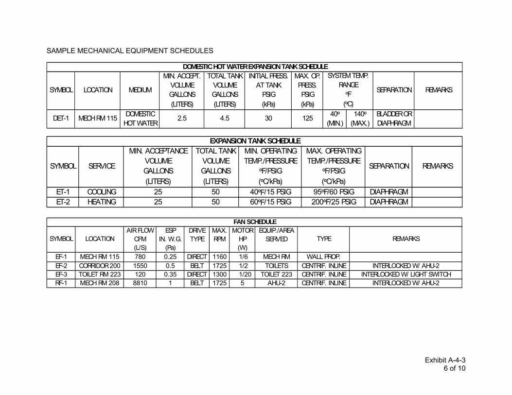
Exhibit A-4-3 6 of 10
SAMPLE MECHANICAL EQUIPMENT SCHEDULES
MIN. ACCEPT. TOTAL TANK INITIAL PRESS. MAX. OP.VOLUME VOLUME AT TANK PRESS.GALLONS GALLONS PSIG PSIG(LITERS) (LITERS) (kPa) (kPa)
DOMESTIC 40º 140º BLADDER ORHOT WATER (MIN.) (MAX.) DIAPHRAGM
30DET-1
DOMESTIC HOT WATER EXPANSION TANK SCHEDULE
SYMBOL LOCATION MEDIUM
2.5 4.5 125MECH RM 115
(ºC)
REMARKSSEPARATION
SYSTEM TEMP.RANGE
ºF
MIN. ACCEPTANCE TOTAL TANK MIN. OPERATING MAX. OPERATINGVOLUME VOLUME TEMP./PRESSURE TEMP./PRESSUREGALLONS GALLONS ºF/PSIG ºF/PSIG(LITERS) (LITERS) (ºC/kPa) (ºC/kPa)
ET-1 COOLING 25 50 40ºF/15 PSIG 95ºF/60 PSIG DIAPHRAGMET-2 HEATING 25 50 60ºF/15 PSIG 200ºF/25 PSIG DIAPHRAGM
EXPANSION TANK SCHEDULE
SYMBOL SERVICE SEPARATION REMARKS
AIR FLOW ESP DRIVE MAX. MOTOR EQUIP./AREACFM IN. W.G. TYPE RPM HP SERVED(L/S) (Pa) (W)
EF-1 MECH RM 115 780 0.25 DIRECT 1160 1/6 MECH RM WALL PROP.EF-2 CORRIDOR 200 1550 0.5 BELT 1725 1/2 TOILETS CENTRIF. INLINE INTERLOCKED W/ AHU-2EF-3 TOILET RM 223 120 0.35 DIRECT 1300 1/20 TOILET 223 CENTRIF. INLINE INTERLOCKED W/ LIGHT SWITCHRF-1 MECH RM 208 8810 1 BELT 1725 5 AHU-2 CENTRIF. INLINE INTERLOCKED W/ AHU-2
FAN SCHEDULE
REMARKSTYPESYMBOL LOCATION

Exhibit A-4-3 7 of 10
SAMPLE MECHANICAL EQUIPMENT SCHEDULES
MIN. FREE MAX. FACE AIR FLOW
AREA VELOCITY CFM
SQ. FEET FT./MIN. (M3/S)
(SQ. METERS) (M/S)1ST FLOOR EXHAUST BIRD SCREEN,
RM. 125 FOR EF-5 BACK DRAFT DAMPER2ND FLOOR INTAKE FOR
MECH. RM. 208 AHU-1 & 22ND FLOOR RELIEF BIRD SCREEN,
MECH. RM. 208 FOR AHU-2 MOTOR OPERATED DAMPERINTERLOCK W/ AHU-2
8 500 4000 BIRD SCREEN
LOUVER SCHEDULE
REMARKSACCESSORIESSERVICELOCATIONSYMBOL
L-1 0.1 750 75
L-3 1.46 750 1095
L-2
INLET OUTLET PRESS. TEMP. TEMP. WATERSIZE SIZE SETTING RELIEF RATING
INCHES INCHES PSIG ºF BTUH(mm) (mm) (kPa) (ºC) (kW)
T&PRV-1 1 1/2" FEMALE 1 1/2" FEMALE 150 210º BRONZE-BODY MECH. RM 115 3,000,000 DOMESTIC WATER HEATER DWH-1
T. & P. RELIEF VALVE SCHEDULE
REMARKSCONSTRUCTION LOCATIONSYMBOL
MAX. CONNECTIONFIXTURE FLUID PIPE SIZEUNITS TEMP. INCHES
ºF (mm)(ºC)
WHA-A 1 - 11 180º 1/2 LOCATE IN ACCORDANCE WITH PDI WH 201 STD./PROVIDE ACCESS DOORS AS REQ'D.WHA-B 12 - 32 180º 3/4 LOCATE IN ACCORDANCE WITH PDI WH 201 STD./PROVIDE ACCESS DOORS AS REQ'D.WHA-C 33 - 60 180º 1 LOCATE IN ACCORDANCE WITH PDI WH 201 STD./PROVIDE ACCESS DOORS AS REQ'D.WHA-D 61 - 113 180º 1 1/4 LOCATE IN ACCORDANCE WITH PDI WH 201 STD./PROVIDE ACCESS DOORS AS REQ'D.WHA-E 114 - 154 180º 1 1/2 LOCATE IN ACCORDANCE WITH PDI WH 201 STD./PROVIDE ACCESS DOORS AS REQ'D.WHA-F 155 - 330 180º 2 LOCATE IN ACCORDANCE WITH PDI WH 201 STD./PROVIDE ACCESS DOORS AS REQ'D.
WATER HAMMER ARRESTER SCHEDULE
SYMBOL REMARKS

Exhibit A-4-3 8 of 10
SAMPLE MECHANICAL EQUIPMENT SCHEDULES
CAPACITY STEAM FLOW EWT LWT MAX. MAX. WATERMBH PRESS. RATE ºF ºF WPD VELOCITY(kW) PSIG GPM (ºC) (ºC) FT. HEAD FT./S
(kPa) (L/S) (kPa) (M/S)CV-1 TOILET RM 115 HEATING 32,000 150 585 130º 240º 10 7.25
CONVERTOR SCHEDULE
SYMBOL LOCATION SYSTEM REMARKS
HOT WATER HOT WATER FLOW RATE MAX. PRESS. MAX. OPERATINGTEMP. IN TEMP. OUT OUT DROP PRESS.
ºF ºF GPM PSIG PSIG(ºC) (ºC) (L/S) (kPa) (kPa)
TV-1 MECH. RM 105 140º 120º 25 10 125
SYMBOL LOCATION REMARKS
DOMESTIC HOT WATER TEMPERING VALVE SCHEDULE
CAPACITY FLOW EWT LWT MAX. PRESS. FLOW EWT LWT MAX. PRESS.MBH RATE ºF ºF DROP RATE ºF ºF DROP(kW) GPM (ºC) (ºC) PSIG GPM (ºC) (ºC) PSIG
(L/S) (kPa) (L/S) (kPa)HX-1 1071 27 240º 160º 5 108 150º 170º 5 PLATE & FRAME TYPE
HOT SIDE COLD SIDEHEAT EXCHANGER SCHEDULE
SYMBOL REMARKS
MIN. THROAT MIN. INTAKEHOOD AREA FREE AREATYPE SQ. FEET SQ. FEET
(SQ. METERS) (SQ. METERS)ROOF ABOVE
RM 119INTAKEHD-1
HOOD SCHEDULE
PROVIDE SLOPING ROOF CURB0.820.82AHU-1
SYMBOL LOCATION SERVES REMARKS

Exhibit A-4-3 9 of 10
SAMPLE MECHANICAL EQUIPMENT SCHEDULES
PUMP DISCHARGE MIN. RECEIVER MOTORCAPACITY PRESSURE CAPACITY HP
GPM PSIG GALLONS (W)
(L/S) (kPa) (LITERS)CP-1 DUPLEX 0.006 EACH 2.4 75 1/3
CONDENSATE PUMPING UNIT SCHEDULE
SYMBOL TYPE REMARKS
FCU-1LOCATION RM 104
TOTAL AIRFLOW (CFM (M3/S)) 346
0.A. (CFM (M3/S)) 0EXTERNAL STATIC PRESSURE
IN. W.G. (Pa)FAN SPEED HIGH
ENTERING AIR TEMPERATUREDB/WB (ºF (ºC))
LEAVING AIR TEMPERATUREDB/WB (ºF (ºC))
SENSIBLE LOAD (BTUH (kW)) 6900TOTAL LOAD (BTUH (kW)) 7400
ENT./LVG. WATER TEMPERATUREºF (ºC)
WATER FLOW (GPM (L/S)) 1.2MAX. WATER PRESSURE DROP
FT. HEAD (M. HEAD)ENTERING AIR TEMPERATURE
DB (ºF (ºC))TOTAL LOAD (BTUH (kW)) 8600
ENT./LVG. WATER TEMPERATUREºF (ºC)
WATER FLOW (GPM (L/S)) 0.86MAX. WATER PRESSURE DROP
FT. HEAD (M. HEAD)2" UNIT MOUNTED THROW AWAY
VERTICAL20x28x36
REMARKS
FAN COIL UNIT SCHEDULE
MAX. DIMENSIONS (LxWxH) (INCHES (mm))CABINET TYPEFILTER TYPE
HEATING COIL
67.5º
170º/150º
10
SYMBOL
0.4
SUPPLY FAN
COOLING COIL
76º/62º
58º/54.7º
44º/56º
10
AIR HANDLING STEAM OUTPUTUNIT SERVED LB/HR
(kG/HR)H-1 AHU-1 30
SYMBOL
HUMIDIFIER SCHEDULE
REMARKS

Exhibit A-4-3 10 of 10
SAMPLE MECHANICAL EQUIPMENT SCHEDULES
AHU-1SERVICE CLASSROOMS
LOCATION MECH. RM 115SYSTEM TYPE 2 DECK MULTIZONE UNIT
TOTAL AIR VOLUME (CFM (M 3/S)) 2035
O.A. (CFM (M 3/S)) 855TOTAL EXTERNAL STATIC PRESSURE
IN. W.G. (Pa)REMARKS HORIZONTAL BLOW THRU
TOTAL LOAD (MBH (kW)) 141.6SENSIBLE LOAD (MBH (kW)) 73.1
ENTERING AIR TEMPERATUREDB/WB (ºF (ºC))
LEAVING AIR TEMPERATUREDB/WB (ºF (ºC))
ENT./LVG. WATER TEMPERATUREºF (ºC)
WATER FLOW (GPM (L/S)) 23.6MAX. FACE VELOCITY
FT./MIN. (M/S)MAX. WATER PRESSURE DROP
FT. HEAD (M. HEAD)TOTAL LOAD (MBH (kW)) 93.9
ENTERING AIR TEMPERATUREºF (ºC)
LEAVING AIR TEMPERATUREºF (ºC)
ENT./LVG. WATER TEMPERATUREºF (ºC)
WATER FLOW (GPM (L/S)) 9.39MAX. FACE VELOCITY
FT./MIN. (M/S)MAX. WATER PRESSURE DROP
FT. HEAD (M. HEAD)PRE-FILTER TYPE 2 IN. ANGLED
MAX. FACE VELOCITYFT./MIN. (M/S)
MAX. PRESSURE DROP CLEANIN. W.G. (Pa)EFFICIENCY 30%
FINAL FILTER TYPE 12 IN. PLEATEDMAX. FACE VELOCITY
FT./MIN. (M/S)MAX. PRESSURE DROP CLEAN
IN. W.G. (Pa)EFFICIENCY 80% - 85%
2 DECK W/ 3 ZONES
AIR HANDLING UNIT SCHEDULESYMBOL
SUPPLY FAN
1.5
170º/150º
500
COOLING COIL
84.1º/72.3º
52.3º/50.7º
44º/56º
500
10
5
HEATING COIL
REMARKS
FILTER
300
0.28
500
0.5
52º
90º
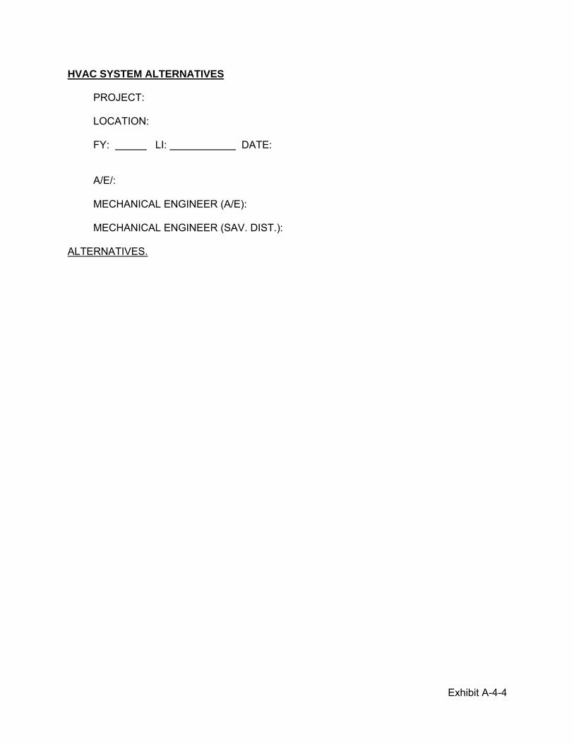
Exhibit A-4-4
HVAC SYSTEM ALTERNATIVES PROJECT: LOCATION: FY: LI: DATE: A/E/: MECHANICAL ENGINEER (A/E): MECHANICAL ENGINEER (SAV. DIST.): ALTERNATIVES.

Exhibit A-4-5
SAVANNAH DISTRICT CERTIFICATE FOR DESIGN OF MECHANICAL ROOM BASE FY - CONTRACT NO. PROJECT L.I. FIRM NAME DATE I certify that the mechanical room has sufficient space to accommodate, and service all mechanical equipment shown on the mechanical drawing(s). DATE Signature of Architect DATA Signature of District Reviewer/Checker