chapter forty-two bicycle facilities of local roads and streets manual . chapter forty-two . bicycle...
TRANSCRIPT
BUREAU OF LOCAL ROADS AND STREETS MANUAL
Chapter Forty-two
BICYCLE FACILITIES


BUREAU OF LOCAL ROADS & STREETS Oct 2013 BICYCLE FACILITIES 42(i)
Chapter Forty-two BICYCLE FACILITIES
Table of Contents
Section Page 42-1 BICYCLE ACCOMMODATIONS ........................................................................... 42-1(1)
42-1.01 Definitions ............................................................................................ 42-1(1) 42-1.02 Policy ................................................................................................... 42-1(2) 42-1.03 Needs Assessment .............................................................................. 42-1(2)
42-2 CHECKLIST FOR BICYCLE ACCOMMODATIONS .............................................. 42-2(1)
42-2.01 Bicycle Travel Generators in the Project Vicinity .................................. 42-2(1) 42-2.02 Public Coordination .............................................................................. 42-2(3) 42-2.03 Assessment of Bicycle Travel............................................................... 42-2(3)
42-3 BICYCLE FACILITY DESIGN GUIDELINES.......................................................... 42-3(1)
42-3.01 Bicycle Facility Design Analysis ........................................................... 42-3(1)
42-3.01(a) Data Collection and Flow Analysis ................................... 42-3(1) 42-3.01(b) Bicycle Level of Service ................................................... 42-3(1) 42-3.01(c) Safety Analysis ................................................................ 42-3(1) 42-3.01(d) Bicycle Demand Analysis ................................................. 42-3(2)
42-3.02 Separated, Shared Use, and Sidepath Bicycle Paths ........................... 42-3(2)
42-3.02(a) Bike Paths Versus Sidewalks ........................................... 42-3(2) 42-3.02(b) Width ............................................................................... 42-3(2) 42-3.02(c) Surface Type ................................................................... 42-3(2) 42-3.02(d) Separation ....................................................................... 42-3(3) 42-3.02(e) Design Speed .................................................................. 42-3(4) 42-3.02(f) Horizontal Alignment ........................................................ 42-3(4) 42-3.02(g) Vertical Alignment ............................................................ 42-3(4) 42-3.02(h) Bike Path Structures ........................................................ 42-3(6) 42-3.02(i) Bike Paths/Highway Crossings ........................................ 42-3(7)
42-3.03 On-Road Bicycle Accommodations ...................................................... 42-3(10)
42-3.03(a) General ............................................................................ 42-3(10) 42-3.03(b) On Rural Roadways ......................................................... 42-3(11) 42-3.03(c) On Urban Roadways ........................................................ 42-3(11) 42-3.03(d) On Existing Roads and Streets ........................................ 42-3(12) 42-3.03(e) Bike Lanes on Highway Structures .................................. 42-3(13)
42-3.04 Bicycle Railroad Crossings ................................................................... 42-3(16) 42-3.05 Incidental Design Factors ..................................................................... 42-3(17) 42-3.06 Signing, Pavement Marking, and Traffic Control................................... 42-3(18)

BUREAU OF LOCAL ROADS & STREETS 42(ii) BICYCLE FACILITIES Oct 2013 42-4 MAINTENANCE .................................................................................................... 42-4(1)
42-5 REFERENCES ...................................................................................................... 42-5(1)

BUREAU OF LOCAL ROADS & STREETS Oct 2013 BICYCLE FACILITIES 42-1(1)
Chapter Forty-two BICYCLE FACILITIES
42-1 BICYCLE ACCOMMODATIONS
42-1.01 Definitions
1. Bicycle. Every vehicle propelled solely by human power upon which any person may ride, having two tandem wheels, except scooters and similar devices. The term “bicycle” in the context of this Chapter also refers to three- and four-wheeled human-powered vehicles, but not children’s tricycles.
2. Bicycle Route (Bike Route). A segment within a system of bikeways designated by the agency having jurisdiction of the facility with appropriate directional and informational markers, with or without a specific bicycle route number, on-pavement striping, or other markings or signage.
3. Bikeway. A generic term for any road, street, path, or traveled way which in some manner is specifically designated for bicycle travel, regardless of whether such facilities are designated for the exclusive use of bicycles or shared with other transportation modes.
4. Bike Lane. The portion of a roadway surface that is designated by pavement markings and signing for the exclusive use of bicyclists.
5. Bicycle Path/Shared-Use Trail/Sidepath. A facility physically separated from the roadway and intended for bicycle or other non-motorized transportation (e.g., pedestrians, disabled persons in wheelchairs, in-line skaters). The terms path and trail generally are describing the same facility. Sidepath refers to a path or trail closely associated with and parallel to a roadway.
6. Bicycle Facilities. A broad term which includes bikeways, shared roadways, shoulders (which may be used by bicyclists), traffic control devices, shelters, and parking facilities for bicycles.
7. Rail-Trail. A shared use path, either paved or unpaved, built within the right-of-way of an existing or former railroad.
8. Shared Lane. A lane of traveled way on any roadway upon which a separate bicycle lane is not designated and which may be legally used by bicyclists regardless of whether such facility is specifically designated as a bikeway.
9. Urbanized Area. An Urbanized Area is a statistical geographic entity designated by the Census Bureau, consisting of a central core and adjacent densely settled territory that together contain at least 50,000 people, generally with an overall population density of at least 1,000 people per square mile.
BUREAU OF LOCAL ROADS & STREETS 42-1(2) BICYCLE FACILITIES Oct 2013 42-1.02 Policy
The local public agency (LPA) should consider the travel needs of all users of a transportation corridor when planning transportation improvements. Bicycle facilities shall be considered on all Federal-aid projects and should also be considered on MFT projects, where practical. This chapter provides a general overview of bicycle planning and design concepts. However, the latest edition of the AASHTO Guide for the Development of Bicycle Facilities should be consulted. If the LPA desires to use another bicycle design standard, the LPA shall provide documentation that the design standard is accepted by FHWA or other national organizations. For all LPA projects that are on, impact, or cross a state route, the LPA shall follow Chapter 17 of the BDE Manual.
42-1.03 Needs Assessment
The LPA shall determine the need for bicycle accommodations based on anticipated demand, community plans, and traffic safety considerations. The following guidelines should be considered:
• The highway or street is designated as a bikeway on a regionally or locally adopted bike plan or published in a regional or locally adopted map as a recommended bike route.
• The 5-year projected two-way bicycle traffic volume after completion of the project is 25 ADT or greater during the peak three months of the bicycling season on a highway or street where the current vehicular traffic exceeds 1000 ADT. See Section 42-3.01 for information concerning bicycle demand analysis.
• The route provides primary access to a park, recreational area, school, other designated bikeways/trails, or other significant destination.
• The route provides unique access across a natural or man-made barrier (e.g., bridges over rivers, roadways, railroads) or under access-controlled facilities and roadways.
• The highway project negatively affects the recreational or transportation utility of an independent bikeway or trail. Highway projects will negatively affect at-grade bikeways, paths, and trails where they are severed, when the projected roadway traffic volumes increase to a level that prevents safe crossings, or where the widening of the roadway prohibits sufficient time for safe crossing.
• Provisions may also be necessary to safely accommodate bicycle traffic on highways where bridge decks are being replaced or rehabilitated.
The following additional guidance is provided to determine bicycle accommodation need where bicycle travel is difficult to predict:
1. Urbanized Areas. Because of the potential for bicycle travel, bicycle accommodation will likely be needed in the majority of urbanized areas, particularly at points of community development that generate, attract, or result in commercial, recreational, or institutional establishments near or along highways, at present or in the planned future.
2. Rural Towns. Bicycle accommodation may be needed in rural towns located on main highways where bicycle travel within the community and from the outlying populated areas could justify such accommodation.
BUREAU OF LOCAL ROADS & STREETS Oct 2013 BICYCLE FACILITIES 42-1(3) 3. Rural Highway Projects. Bicycle accommodation will likely be needed on rural highway
projects that provide unique access over a major barrier (e.g., river) or that connect an urbanized area to a rural attraction (e.g., park).
4. Unpopulated Rural Areas. In unpopulated rural areas, typical origins and destinations are far less frequent. Thus, bicycle accommodation may not be needed. However, when roadways provide unique access or bicycle accomodations are called for in approved or adopted plans, then bicycle accommodations should be considered.
Section 42-2 provides checklists to assist the LPA in deciding if bicycle facilities should be included. If it is determined that the volume and character of existing and future bicycle travel in the vicinity of a project justify the provision of bicycle facilities, provide the appropriate accommodations as discussed in Section 42-3.

BUREAU OF LOCAL ROADS & STREETS 42-1(4) BICYCLE FACILITIES Oct 2013
BUREAU OF LOCAL ROADS & STREETS Oct 2013 BICYCLE FACILITIES 42-2(1) 42-2 CHECKLIST FOR BICYCLE ACCOMMODATIONS
Include a checklist in the Project Development Reports for Federal projects where Section 42-1.03 requires the evaluation of the potential for bicycle accommodations. If provisions for adequate bicycle accommodations are already designed, provide a descriptive statement regarding the bicycle accommodations in lieu of a checklist. A checklist may also be used as a guide for bicycle accommodations on projects constructed with other funds.
42-2.01 Bicycle Travel Generators in the Project Vicinity
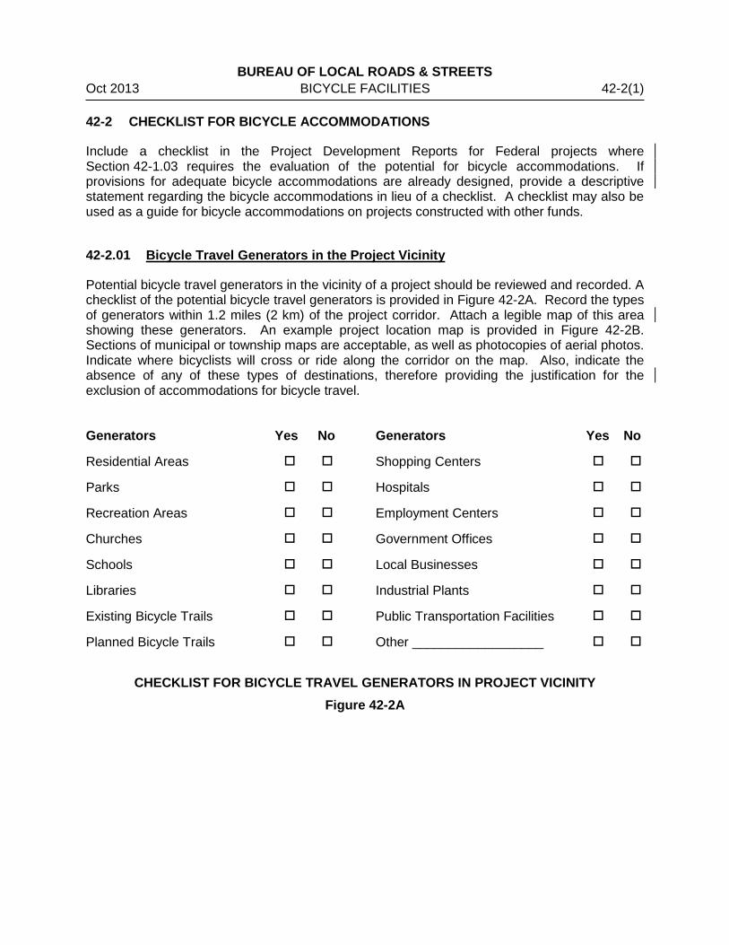
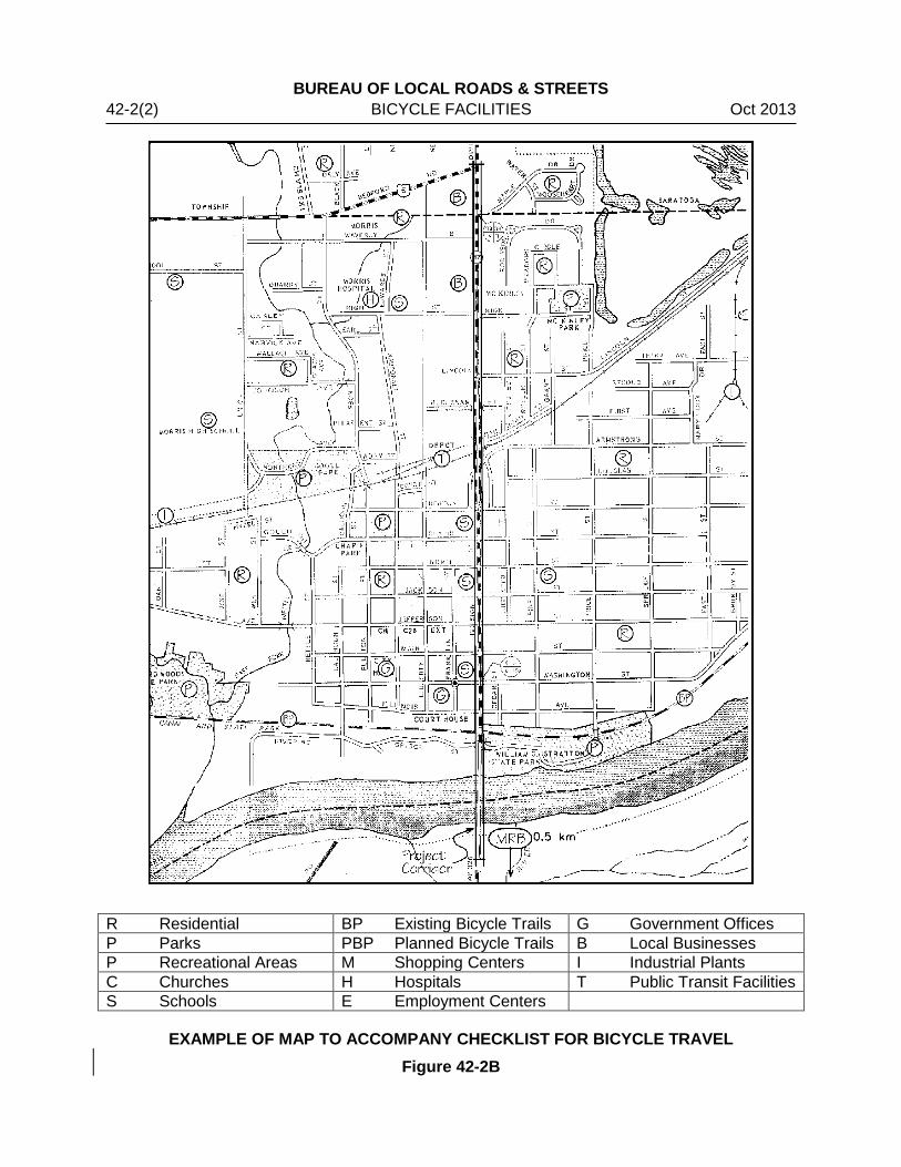
Potential bicycle travel generators in the vicinity of a project should be reviewed and recorded. A checklist of the potential bicycle travel generators is provided in Figure 42-2A. Record the types of generators within 1.2 miles (2 km) of the project corridor. Attach a legible map of this area showing these generators. An example project location map is provided in Figure 42-2B. Sections of municipal or township maps are acceptable, as well as photocopies of aerial photos. Indicate where bicyclists will cross or ride along the corridor on the map. Also, indicate the absence of any of these types of destinations, therefore providing the justification for the exclusion of accommodations for bicycle travel. Generators Yes No Generators Yes No
Residential Areas Shopping Centers
Parks Hospitals
Recreation Areas Employment Centers
Churches Government Offices
Schools Local Businesses
Libraries Industrial Plants
Existing Bicycle Trails Public Transportation Facilities
Planned Bicycle Trails Other __________________
CHECKLIST FOR BICYCLE TRAVEL GENERATORS IN PROJECT VICINITY
Figure 42-2A
BUREAU OF LOCAL ROADS & STREETS 42-2(2) BICYCLE FACILITIES Oct 2013
R Residential BP Existing Bicycle Trails G Government Offices P Parks PBP Planned Bicycle Trails B Local Businesses P Recreational Areas M Shopping Centers I Industrial Plants C Churches H Hospitals T Public Transit Facilities S Schools E Employment Centers
EXAMPLE OF MAP TO ACCOMPANY CHECKLIST FOR BICYCLE TRAVEL Figure 42-2B
BUREAU OF LOCAL ROADS & STREETS Oct 2013 BICYCLE FACILITIES 42-2(3) 42-2.02 Public Coordination
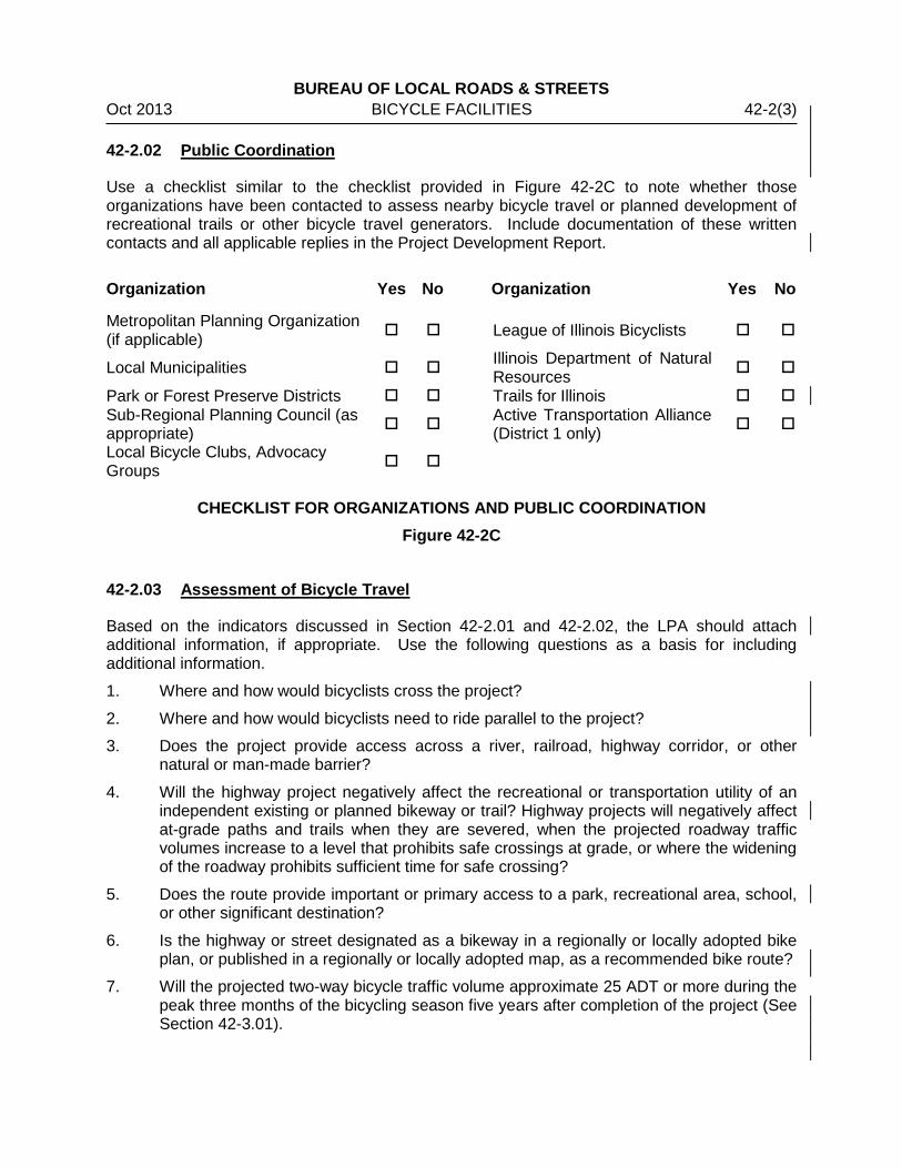
Use a checklist similar to the checklist provided in Figure 42-2C to note whether those organizations have been contacted to assess nearby bicycle travel or planned development of recreational trails or other bicycle travel generators. Include documentation of these written contacts and all applicable replies in the Project Development Report.
Organization Yes No Organization Yes No
Metropolitan Planning Organization (if applicable) League of Illinois Bicyclists
Local Municipalities Illinois Department of Natural Resources
Park or Forest Preserve Districts Trails for Illinois Sub-Regional Planning Council (as appropriate) Active Transportation Alliance
(District 1 only)
Local Bicycle Clubs, Advocacy Groups
CHECKLIST FOR ORGANIZATIONS AND PUBLIC COORDINATION
Figure 42-2C
42-2.03 Assessment of Bicycle Travel
Based on the indicators discussed in Section 42-2.01 and 42-2.02, the LPA should attach additional information, if appropriate. Use the following questions as a basis for including additional information.
1. Where and how would bicyclists cross the project?
2. Where and how would bicyclists need to ride parallel to the project?
3. Does the project provide access across a river, railroad, highway corridor, or other natural or man-made barrier?
4. Will the highway project negatively affect the recreational or transportation utility of an independent existing or planned bikeway or trail? Highway projects will negatively affect at-grade paths and trails when they are severed, when the projected roadway traffic volumes increase to a level that prohibits safe crossings at grade, or where the widening of the roadway prohibits sufficient time for safe crossing?
5. Does the route provide important or primary access to a park, recreational area, school, or other significant destination?
6. Is the highway or street designated as a bikeway in a regionally or locally adopted bike plan, or published in a regionally or locally adopted map, as a recommended bike route?
7. Will the projected two-way bicycle traffic volume approximate 25 ADT or more during the peak three months of the bicycling season five years after completion of the project (See Section 42-3.01).

BUREAU OF LOCAL ROADS & STREETS 42-2(4) BICYCLE FACILITIES Oct 2013
BUREAU OF LOCAL ROADS & STREETS Oct 2013 BICYCLE FACILITIES 42-3(1) 42-3 BICYCLE FACILITY DESIGN GUIDELINES
Use the current edition of AASHTO’s Guide for the Development of Bicycle Facilities as the primary source for planning and design guidance. In addition, FHWA has recommended the use of the National Association of City Transportation Officials’ Urban Bikeway Design Guide and the Institute of Transportation Engineers’ Designing Urban Walkable Thoroughfares for the development of bikeways in urban areas.
42-3.01 Bicycle Facility Design Analysis
In order to build or improve bicycle facilities, the LPA should analyze existing conditions, as well as public and stakeholder input, to determine the type and capacity of any bicycle facility. The methods described in this section provide the LPA with options to synthesize a large amount of complex data. However, the LPA should consider which method or combination of methods to use. 42-3.01(a) Data Collection and Flow Analysis
Bicycle related data collection is an important part of understanding, planning, maintaining, and operating a bicycle facility. Bicycle count and movement analysis may be used to:
• Identify Corridors
• Understand Patterns of Usage
• Forecast Bicycle Travel Demand
• Track Community-wide Bicycle Use
• Project Future Bicycle Use
• Analyze Specific Travel Patterns If bicycle traffic volume data is not available, the LPA may estimate the bicycle traffic volume by multiplying the highway traffic volume data by the bicycle commuting percentage from census data. However, this method is most accurate in the urbanized area where census tracts or more compact. 42-3.01(b) Bicycle Level of Service
Bicycle Level of Service (Bicycle LOS) evaluates bicyclists’ perceived safety and comfort with respect to motor vehicle traffic while traveling in a roadway corridor. Bicycle LOS provides a score for each roadway that indicates how comfortable a typical adult bicyclist would feel while riding along that roadway during peak travel conditions. See Section 27-6.04 and the Highway Capacity Manual for more information. 42-3.01(c) Safety Analysis
Analysis of crash data to identify intersections or corridors where most bicycle-motor vehicle crashes occur, including “dooring” type crashes, will assist identifying locations for bicycle facilities.
BUREAU OF LOCAL ROADS & STREETS 42-3(2) BICYCLE FACILITIES Oct 2013 42-3.01(d) Bicycle Demand Analysis
Evaluating bicycle travel demand shares some similarities to motor vehicle travel demand modeling by forecasting future needs based on objective data inputs. However, bicycle travel demand should also account for latent demand (demand that is not apparent, but underlying). Therefore, bicycle travel demand methods make assumptions regarding how many people would choose to bicycle along a given corridor if bicycle accommodations are made. Types of bicycle demand analysis include:
• Comparison Study
• Sketch Plan Methods
• Market Analysis/ Land Use Models
• Discrete Choice Survey Models For additional information on bicycle demand analysis, see Section 2.6.5 of AASHTO’s Guide for the Development of Bicycle Facilities, 4th Edition.
42-3.02 Separated, Shared Use, and Sidepath Bicycle Paths
The principles for geometric design of bike paths are the same as those used in general highway design. While exclusive bicycle use of a bicycle path is often ideal, it seldom occurs. For this reason, pedestrian, in-line skaters, and other anticipated use is always considered in the design of the facility. Include separate areas to minimize the conflicts arising from the different speeds of these transportation modes, where practical. This Section provides guidance specific to the design of bike paths. Also, see the latest edition of the AASHTO Guide for the Development of Bicycle Facilities for more detailed information. 42-3.02(a) Bike Paths Versus Sidewalks
Sidewalks are generally not suitable for bicycle travel, primarily because of their narrow width and multiple opportunities for conflicts with driveways and commercial entrances. However, some suburban sidewalks may be preferable to on-road accommodations, particularly if they provide adequate width, do not have excessive number of driveways/conflict points, and are located on both sides of the roadway. 42-3.02(b) Width
Widths for shared use bicycle paths will vary in accordance with the conditions illustrated in Figure 42-3A. Figure 42-3B illustrates the minimum cross sections for two-way, shared-use paths. 42-3.02(c) Surface Type
Hot mix asphalt (HMA) or concrete pavement surfaces are preferred over crushed aggregate surfaces. In some situations, a bituminous surface treatment (BST) over an aggregate base may be adequate for bikeways. The LPA should consider the life cycle cost when selecting the bikeway surface type.
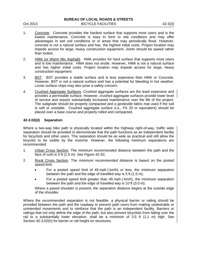
BUREAU OF LOCAL ROADS & STREETS Oct 2013 BICYCLE FACILITIES 42-3(3) 1. Concrete. Concrete provides the hardest surface that supports most users and is the
lowest maintenance. Concrete is easy to form to site conditions and may offer advantages in wet soil conditions or in areas that may periodically flood. However, concrete is not a natural surface and has the highest initial costs. Project location may impede access for large, heavy construction equipment. Joints should be sawed rather than tooled.
2. HMA (or Warm Mix Asphalt). HMA provides for hard surface that supports most users and is low maintenance. HMA does not erode. However, HMA is not a natural surface and has higher initial costs. Project location may impede access for large, heavy construction equipment.
3. BST. BST provides a stable surface and is less expensive than HMA or Concrete. However, BST is not a natural surface and has a potential for bleeding in hot weather. Loose surface chips may also pose a safety concern.
4. Crushed Aggregate Surfaces. Crushed aggregate surfaces are the least expensive and provides a permeable surface. However, crushed aggregate surfaces provide lower level of service and require substantially increased maintenance over the life of the project. The subgrade should be properly compacted and a geotextile fabric mat used if the soil is soft or unstable. Crushed aggregate surface (i.e., FA 20 or equivalent) should be placed over a base course and properly rolled and compacted.
42-3.02(d) Separation
Where a two-way bike path is physically located within the highway right-of-way, traffic wide separation should be provided to demonstrate that the path functions as an independent facility for bicyclists and other users. This separation should be as wide as practical and still allow the bicyclist to be visible by the motorist. However, the following minimum separations are recommended:
1. Urban Cross Section. The minimum recommended distance between the path and the face of curb is 5 ft (1.5 m). See Figure 42-3C.
2. Rural Cross Section. The minimum recommended distance is based on the posted speed limit. • For a posted speed limit of 45 mph ( km/h) or less, the minimum separation
between the path and the edge of travelled way is 5 ft (1.5 m). • For a posted speed limit greater than 45 mph ( km/h), the minimum separation
between the path and the edge of travelled way is 10 ft (3.0 m). Where a paved shoulder is present, the separation distance begins at the outside edge of the shoulder.
Where the recommended separation is not feasible, a physical barrier or railing should be provided between the path and the roadway to prevent path users from making undesirable or unintended movements and to reinforce that the path is an independent facility. Barriers or railings that not only define the edge of the path, but also prevent bicyclists from falling over the rail to a substantially lower elevation, shall be a minimum of 3.5 ft (1.1 m) high. See Section 42-3.02(h) for barrier or rail height on structures.
BUREAU OF LOCAL ROADS & STREETS 42-3(4) BICYCLE FACILITIES Oct 2013 42-3.02(e) Design Speed
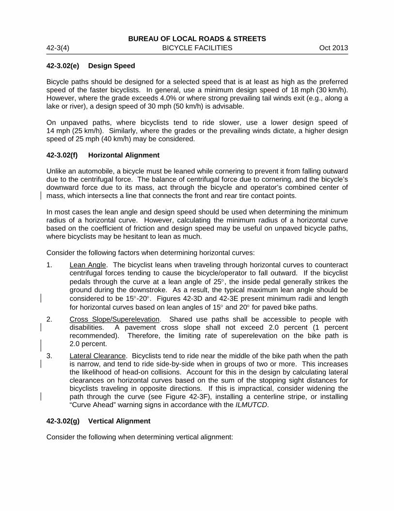
Bicycle paths should be designed for a selected speed that is at least as high as the preferred speed of the faster bicyclists. In general, use a minimum design speed of 18 mph (30 km/h). However, where the grade exceeds 4.0% or where strong prevailing tail winds exit (e.g., along a lake or river), a design speed of 30 mph (50 km/h) is advisable. On unpaved paths, where bicyclists tend to ride slower, use a lower design speed of 14 mph (25 km/h). Similarly, where the grades or the prevailing winds dictate, a higher design speed of 25 mph (40 km/h) may be considered. 42-3.02(f) Horizontal Alignment
Unlike an automobile, a bicycle must be leaned while cornering to prevent it from falling outward due to the centrifugal force. The balance of centrifugal force due to cornering, and the bicycle’s downward force due to its mass, act through the bicycle and operator’s combined center of mass, which intersects a line that connects the front and rear tire contact points. In most cases the lean angle and design speed should be used when determining the minimum radius of a horizontal curve. However, calculating the minimum radius of a horizontal curve based on the coefficient of friction and design speed may be useful on unpaved bicycle paths, where bicyclists may be hesitant to lean as much. Consider the following factors when determining horizontal curves:
1. Lean Angle. The bicyclist leans when traveling through horizontal curves to counteract centrifugal forces tending to cause the bicycle/operator to fall outward. If the bicyclist pedals through the curve at a lean angle of 25°, the inside pedal generally strikes the ground during the downstroke. As a result, the typical maximum lean angle should be considered to be 15°-20°. Figures 42-3D and 42-3E present minimum radii and length for horizontal curves based on lean angles of 15° and 20° for paved bike paths.
2. Cross Slope/Superelevation. Shared use paths shall be accessible to people with disabilities. A pavement cross slope shall not exceed 2.0 percent (1 percent recommended). Therefore, the limiting rate of superelevation on the bike path is 2.0 percent.
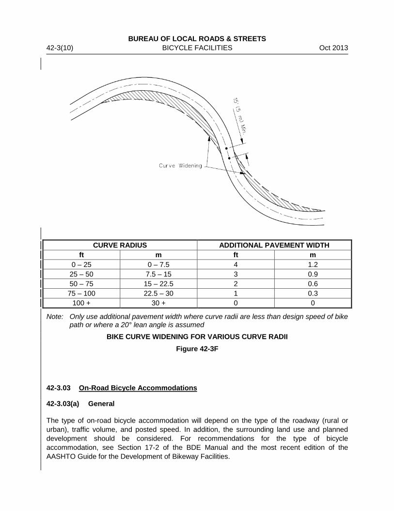
3. Lateral Clearance. Bicyclists tend to ride near the middle of the bike path when the path is narrow, and tend to ride side-by-side when in groups of two or more. This increases the likelihood of head-on collisions. Account for this in the design by calculating lateral clearances on horizontal curves based on the sum of the stopping sight distances for bicyclists traveling in opposite directions. If this is impractical, consider widening the path through the curve (see Figure 42-3F), installing a centerline stripe, or installing “Curve Ahead” warning signs in accordance with the ILMUTCD.
42-3.02(g) Vertical Alignment
Consider the following when determining vertical alignment:

BUREAU OF LOCAL ROADS & STREETS Oct 2013 BICYCLE FACILITIES 42-3(5) 1. Grades. The maximum grade of a shared use path shall comply with the latest edition
of the Public Rights of Way Accessibility Guidelines. Grades in excess of 5.0% shall be evaluated concerning the need for ADA compliance. In addition, grades in excess of 3.0% are impractical for unpaved paths because of increased erosion potential. Mitigate excessive grades using the following options:
• Provide additional width to permit slower bicyclists to dismount and walk. • Provide signing alerting bicyclists to the maximum percent of grade, per the
ILMUTCD. • Post a recommended descent speed. • Provide stopping sight distances that exceed the minimums. • Provide horizontal clearances that exceed the minimums. • Widen the path or include short switchbacks to contain the speed of descending
bicyclists. • Provide extra shoulder width for riders to dismount and rest.
2. Sight Distance. For sight distance calculations, assume the bicyclist’s combined perception and brake reaction time is 2.5 seconds. The height of eye for a bicyclist is 4.5 ft (1.4 m) and the height of object is 0.0 ft (0.0 m). The coefficient of friction between tire and pavement is 0.16 for wet-weather braking conditions. Use the following equations to determine the applicable sight distance for bicycle paths:
( ) V67.3Gf30
VS2
+±
= Equation 42-3.1 (US Customary)
( ) 4.1V
Gf254VS
2
+±
= Equation (42-3.1 Metric)
Where:
S = stopping sight distance, ft (m) V = velocity, mph (km/h) f = coefficient of friction (use 0.16) G = grade, ft/ft (m/m) (rise/run)
3. Vertical Curve Lengths. Using the sight distance data and Equation 42-3.2, determine the vertical curve lengths. Use the following equations:
( )221
2
h+h200
AS=L (Equation 42-3.2)
KA=L (Equation 42-3.3)
Where: L = length of vertical curve, ft (m) A = algebraic difference between the two tangent grades, % S = sight distance, ft (m) h1 = height of eye above road surface, ft (m) h2 = height of object above road surface, ft (m) K = horizontal distance needed to produce a 1.0% change in gradient, ft/% (m/%)
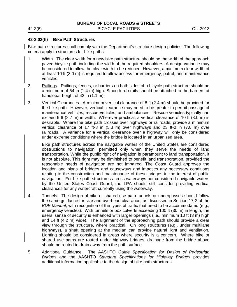
BUREAU OF LOCAL ROADS & STREETS 42-3(6) BICYCLE FACILITIES Oct 2013 42-3.02(h) Bike Path Structures Bike path structures shall comply with the Department’s structure design policies. The following criteria apply to structures for bike paths:
1. Width. The clear width for a new bike path structure should be the width of the approach paved bicycle path including the width of the required shoulders. A design variance may be considered to allow the clear width to be reduced. However, a minimum clear width of at least 10 ft (3.0 m) is required to allow access for emergency, patrol, and maintenance vehicles.
2. Railings. Railings, fences, or barriers on both sides of a bicycle path structure should be a minimum of 54 in (1.4 m) high. Smooth rub rails should be attached to the barriers at handlebar height of 42 in (1.1 m).
3. Vertical Clearances. A minimum vertical clearance of 8 ft (2.4 m) should be provided for the bike path. However, vertical clearance may need to be greater to permit passage of maintenance vehicles, rescue vehicles, and ambulances. Rescue vehicles typically can exceed 9 ft (2.7 m) in width. Wherever practical, a vertical clearance of 10 ft (3.0 m) is desirable. Where the bike path crosses over highways or railroads, provide a minimum vertical clearance of 17 ft-3 in (5.3 m) over highways and 23 ft-0 in (7.0 m) over railroads. A variance for a vertical clearance over a highway will only be considered under extreme conditions where the bridge is located in an urbanized area.
Bike path structures across the navigable waters of the United States are considered obstructions to navigation, permitted only when they serve the needs of land transportation. While the public right of navigation is paramount to land transportation, it is not absolute. This right may be diminished to benefit land transportation, provided the reasonable needs of navigation are not impaired. The Coast Guard approves the location and plans of bridges and causeways and imposes any necessary conditions relating to the construction and maintenance of these bridges in the interest of public navigation. For bike path structures across waterways not considered navigable waters by the United States Coast Guard, the LPA should still consider providing vertical clearances for any watercraft currently using the waterway.
4. Tunnels. The design of bike or shared use path tunnels or underpasses should follow the same guidance for size and overhead clearance, as discussed in Section 17-2 of the BDE Manual, with recognition of the types of traffic that need to be accommodated (e.g., emergency vehicles). With tunnels or box culverts exceeding 100 ft (30 m) in length, the users’ sense of security is enhanced with larger openings (i.e., minimum 10 ft (3 m) high and 14 ft (4.2 m) wide). The alignment of the approaching path should provide a clear view through the structure, where practical. On long structures (e.g., under multilane highways), a shaft opening at the median can provide natural light and ventilation. Lighting should be considered in areas where security is a concern. Where bike or shared use paths are routed under highway bridges, drainage from the bridge above should be routed to drain away from the path surface.
5. Additional Guidance. The AASHTO Guide Specification for Design of Pedestrian Bridges and the AASHTO Standard Specifications for Highway Bridges provides additional information applicable to the design of bike path structures.
BUREAU OF LOCAL ROADS & STREETS Oct 2013 BICYCLE FACILITIES 42-3(7) 42-3.02(i) Bike Paths/Highway Crossings
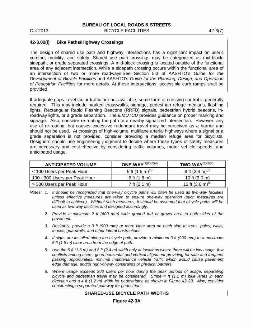
The design of shared use path and highway intersections has a significant impact on user’s comfort, mobility, and safety. Shared use path crossings may be categorized as mid-block, sidepath, or grade separated crossings. A mid-block crossing is located outside of the functional area of any adjacent intersection. While a sidepath crossing occurs within the functional area of an intersection of two or more roadways.See Section 5.3 of AASHTO’s Guide for the Development of Bicycle Facilities and AASHTO’s Guide for the Planning, Design, and Operation of Pedestrian Facilities for more details. At these intersections, accessible curb ramps shall be provided. If adequate gaps in vehicular traffic are not available, some form of crossing control is generally required. This may include marked crosswalks, signage, pedestrian refuge medians, flashing lights, Rectangular Rapid Flashing Beacons (RRFB) signals, pedestrian hybrid beacons, in-roadway lights, or a grade separation. The ILMUTCD provides guidance on proper marking and signage. Also, consider re-routing the path to a nearby signalized intersection. However, any use of re-routing that causes excessive redundant travel may be perceived as a barrier and should not be used. At crossings of high-volume, multilane arterial highways where a signal or a grade separation is not provided, consider providing a median refuge area for bicyclists. Designers should use engineering judgment to decide where these types of safety measures are necessary and cost-effective by considering traffic volumes, motor vehicle speeds, and anticipated usage.
ANTICIPATED VOLUME ONE-WAY(1)(2)(3)(4) TWO-WAY(2)(3)(4)
< 100 Users per Peak Hour 5 ft (1.5 m)(5) 8 ft (2.4 m)(5) 100 - 300 Users per Peak Hour 6 ft (1.8 m) 10 ft (3.0 m) > 300 Users per Peak Hour 7 ft (2.1 m) 12 ft (3.6 m)(6)
Notes: 1. It should be recognized that one-way bicycle paths will often be used as two-way facilities unless effective measures are taken to ensure one-way operation (such measures are difficult to achieve). Without such measures, it should be assumed that bicycle paths will be used as two-way facilities and designed accordingly.
2. Provide a minimum 2 ft (600 mm) wide graded turf or gravel area to both sides of the pavement.
3. Desirably, provide a 3 ft (900 mm) or more clear area on each side to trees, poles, walls, fences, guardrails, and other lateral obstructions.
4. If signs are installed along the bicycle path, provide a minimum 3 ft (900 mm) to a maximum 6 ft (1.8 m) clear area from the edge of path.
5. Use the 5 ft (1.5 m) and 8 ft (2.4 m) width only at locations where there will be low usage, few conflicts among users, good horizontal and vertical alignment providing for safe and frequent passing opportunities, minimal maintenance vehicle traffic which would cause pavement edge damage, and/or right-of-way constraints or physical barriers.
6. Where usage exceeds 300 users per hour during the peak periods of usage, separating bicycle and pedestrian travel may be considered. Stripe 4 ft (1.2 m) bike lanes in each direction and a 4 ft (1.2 m) width for pedestrians, as shown in Figure 42-3B. Also, consider constructing a separated pathway for pedestrians.
SHARED-USE BICYCLE PATH WIDTHS Figure 42-3A

BUREAU OF LOCAL ROADS & STREETS 42-3(8) BICYCLE FACILITIES Oct 2013
TYPICAL CROSS SECTIONS FOR TWO-WAY, SHARED-USE BICYCLE PATHS Figure 42-3B
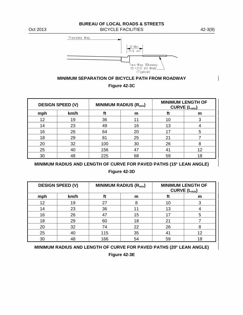
BUREAU OF LOCAL ROADS & STREETS Oct 2013 BICYCLE FACILITIES 42-3(9)
MINIMUM SEPARATION OF BICYCLE PATH FROM ROADWAY Figure 42-3C
DESIGN SPEED (V) MINIMUM RADIUS (Rmin) MINIMUM LENGTH OF
CURVE (Lmin) mph km/h ft m ft m 12 19 36 11 10 3 14 23 49 16 13 4 16 26 64 20 17 5 18 29 81 25 21 7 20 32 100 30 26 8 25 40 156 47 41 12 30 48 225 68 59 18
MINIMUM RADIUS AND LENGTH OF CURVE FOR PAVED PATHS (15° LEAN ANGLE) Figure 42-3D
DESIGN SPEED (V) MINIMUM RADIUS (Rmin) MINIMUM LENGTH OF
CURVE (Lmin) mph km/h ft m ft m 12 19 27 8 10 3 14 23 36 11 13 4 16 26 47 15 17 5 18 29 60 18 21 7 20 32 74 22 26 8 25 40 115 35 41 12 30 48 166 54 59 18
MINIMUM RADIUS AND LENGTH OF CURVE FOR PAVED PATHS (20° LEAN ANGLE) Figure 42-3E
BUREAU OF LOCAL ROADS & STREETS 42-3(10) BICYCLE FACILITIES Oct 2013
CURVE RADIUS ADDITIONAL PAVEMENT WIDTH ft m ft m
0 – 25 0 – 7.5 4 1.2 25 – 50 7.5 – 15 3 0.9 50 – 75 15 – 22.5 2 0.6 75 – 100 22.5 – 30 1 0.3
100 + 30 + 0 0
Note: Only use additional pavement width where curve radii are less than design speed of bike path or where a 20° lean angle is assumed
BIKE CURVE WIDENING FOR VARIOUS CURVE RADII Figure 42-3F
42-3.03 On-Road Bicycle Accommodations
42-3.03(a) General
The type of on-road bicycle accommodation will depend on the type of the roadway (rural or urban), traffic volume, and posted speed. In addition, the surrounding land use and planned development should be considered. For recommendations for the type of bicycle accommodation, see Section 17-2 of the BDE Manual and the most recent edition of the AASHTO Guide for the Development of Bikeway Facilities.
BUREAU OF LOCAL ROADS & STREETS Oct 2013 BICYCLE FACILITIES 42-3(11) 42-3.03(b) On Rural Roadways
Bicycle accommodation on rural cross sections consists of paving a portion of the shoulder. In addition to the benefits to the bicyclist, paved shoulders offer added safety, reduced maintenance, and a hard surface off the traveled way for mail delivery and emergency vehicles. In order to accommodate bicyclists, a minimum shoulder width of 4 ft (1.2 m) of smooth paved surface shall be provided. Additional width may be necessary in locations where:
• vehicular speeds are in excess of 45 mph (70 km/h);
• there are a significant number of trucks and recreational vehicles; or
• fixed objects (e.g., traffic signs) are located too close to the bicycle facility. When rumble strips are desired in a paved shoulder and the width of the paved shoulder is 4 ft (1.2 m) to 6 ft (1.8 m), Highway Standard 642006 should be used to accommodate bicyclists. If the paved shoulder is intended for bicyclists, proper pavement marking and signage may be provided. Marked bikeways should be maintained to provide a desirable riding surface and should provide protection from obstacles or barriers by means of increased bikeway width. 42-3.03(c) On Urban Roadways
Bicycle accommodation on urban cross sections consists of providing a shared lane (unmarked or marked) or providing a bike lane to carry bicycles in the same direction as traffic. Bicycle lane width should be determined by context and anticipated use. Bicycle lane width will vary depending on traffic volume and speed, adjacent parking and land uses, and types of highway vehicles.
1. Shared Lanes. On a shared lanes facility, bicyclists and motorists share the same travel lanes without a striped separation. Shared lanes have particular application where physical constraints (e.g., buildings, narrow sidewalks, environmentally sensitive areas) preclude widening a street to provide bike lanes, or on minor roads with low volumes. a. No Specific Accommodation. No specific accommodation is necessary for roadways
with an ADT less than 2,000 ADT and a posted speed limit of 30 mph (50 km/h) or less.
b. Wide Outside Lane. Wide outside lanes should be considered for a bicycle accommodation on roadways with an ADT between 2,000 - 10,000 and a posted speed limit of 30 mph (50 km/h) or less. The shared lane width shall be 14 ft (4.0 m) minimum measured from edge of the gutter pan to the center of the lane line.
Shared lanes may be unmarked. However, the shared lane marking (sharrow) shall be considered as the preferred treatment (see Section 42-3.06). In some instances, it may be advantageous to sign some shared lanes as bicycle routes when providing continuity to other bicycle facilities or when establishing a touring route. See the ILMUTCD for additional guidance on bicycle markings and signage.
2. Bike Lanes. Bike lanes are marked on curbed streets to delineate bicycle traffic from motor vehicle traffic. They are always one-way facilities carrying traffic in the same direction as adjacent motor vehicle traffic. The preferred operating width is 5 ft (1.5 m). However, wider lanes may be desirable under the following conditions:

BUREAU OF LOCAL ROADS & STREETS 42-3(12) BICYCLE FACILITIES Oct 2013
a. Adjacent to Parking Lane. Consider a minimum width of 6 ft (1.8 m) to prevent car door/ bicyclist conflicts. If parking has high turnover and right-of-way is available, a width of 7 ft (2.1 m) is desirable. The bicycle lane should be located between the parking lane and the through traffic lane.
b. High Bicycle Volume without Parking. Consider a minimum width of 6 ft (1.8 m) to allow bicyclists to ride side by side or for passing slower bicyclists.
c. High Speed Highways or Heavy Trucks. Consider a minimum width of 6 ft (1.8 m) that may include an optional 2 ft (0.6 m) striped buffer zone and/or a bi-directional side path to minimize wind blast and other effects.
d. Highways With ADT Greater than 10,000. Consider a minimum width of 6 ft (1.8 m) that may include an optional 2 ft (0.6 m) striped buffer zone and/or a bi-directional side path.
42-3.03(d) On Existing Roads and Streets
1. With Widening. Where right-of-way is adequate roadways may be widened to provide shared roadways, paved shoulders, or bicycle lanes. In areas with sidewalks, the bicycle accommodation should be balanced with the goal of maintaining a high-quality pedestrian environment. If there is no overlay planned as part of the widening, steps should be taken to ensure that there is not a rough joint where bicyclists ride.
2. Without Widening. Bicycle accommodations may also be provided on a roadway by marking or remarking the pavement to reduce the number of lanes, to increase the width of the curb lane, or to add bike lanes. This is commonly referred to as a “road diet”. Consider the following: a. Reduce Travel Lane Width. This option may be considered if the lane widths on
an existing roadway are greater than the minimum required in Chapter 32 and 33. However, engineering judgment should be used to determine the impact to capacity and safety. Factors to consider include operating speeds, volumes, traffic mix, roadway geometrics, land use context, and parking.
b. Reduce Median Width. This option includes reduction or elimination of medians, especially raised curb medians. However, the safety advantages of medians, used as refuge islands for pedestrians and bicyclists, should be considered.
c. Reconfigure or Reduce On-Street Parking. If this option is considered, a parking study may assist in determining impact. Potential solutions include eliminating parking on one side of the street, peak-hour restrictions, or converting diagonal parking to parallel parking. Additional parking spaces may be provided for on side streets or in an off-street parking facility.
d. Reduce Number of Travel Lanes. Reducing the number of travel lanes (“road diet”) may be used to integrate bike lanes on existing roadways. This strategy may be appropriate on: • highways with excess capacity; • two-lane roadways that are being switched to one-way roadways; or • multi-lane roadways being converted to less lanes (e.g.).
See Figure 42-3G for example of a road way with four through-travel lanes converted to a road way with two through-travel lanes and one two-way center left-turn lane. This reconfiguration is the most common form of a “road diet” and is feasible on road ways with an ADT ≤ 20,000.
BUREAU OF LOCAL ROADS & STREETS Oct 2013 BICYCLE FACILITIES 42-3(13) 42-3.03(e) Bike Lanes on Highway Structures
Since structures have a long life and are often far apart, structures are very important in providing non-motorized access over barriers such as highways, railways, waterways, and other barriers and natural features. Maintain a consistent bicycle lane width from the approach roadway across the structure. New highway structures should, at a minimum, equal the width of the approach roadway plus the width of approaching bicycle lanes and/or sidewalks. The bike lane should have a minimum width of 5 ft (1.5 m). Consider the possible need for future bicycle lanes when planning a new structure. Depending on vehicle speeds and volumes, striped buffer areas or barriers may be needed on structures to separate bicyclists and pedestrians from motor vehicles. Minimum cross sections for shared roadway, bicycle lanes, and bicycle paths are shown in Figure 42-3H. Where it is necessary to include a separated bicycle path on a highway bridge, several alternatives should be considered in light of what the geometrics of the bridge will allow. One option is to carry the bicycle path across one side of the structure. This should be considered where:
• the bridge facility will connect to a bicycle path at both ends,
• sufficient width exists on that side of the bridge or can be obtained by widening or restriping lanes, and
• provisions are made to physically separate bicycle traffic from motor vehicle traffic. Another option is to use existing sidewalks as one-way or two-way facilities. This may be advisable where:
• conflicts between bicyclists and pedestrians will not exceed tolerable limits, and
• the existing sidewalks are adequately wide. If the facility cannot provide adequate widths, appropriately sign the facility to warn users of the deficiencies or require bicyclists to dismount and cross the structure as a pedestrian. Section 17-2 of the BDE Manual provides additional design guidance for bicycle or shared use paths on structures. The AASHTO Standard Specifications for Highway Bridges specifies a 4.5 ft (1.4 m) outside railing height. Design on-road bicycle accommodations accordingly. Where bridge projects include bike lane or sidewalk accommodations, the approaches to the structure should ensure a usable facility by continuing the accommodation to logical termini.

BUREAU OF LOCAL ROADS & STREETS 42-3(14) BICYCLE FACILITIES Oct 2013
TYPICAL “ROAD DIET” Figure 42-3G

BUREAU OF LOCAL ROADS & STREETS Oct 2013 BICYCLE FACILITIES 42-3(15)
BIKE LANES AND BIKE PATHS ACROSS HIGHWAY BRIDGES Figure 42-3H
BUREAU OF LOCAL ROADS & STREETS 42-3(16) BICYCLE FACILITIES Oct 2013 42-3.04 Bicycle Railroad Crossings
Bike lane and path intersections with the railroad are more sensitive to the skew angle than the main highway because of the possibility of bicycle or wheelchair wheels being trapped in the rail flangeway. It may be possible to modify the horizontal alignment of a bikeway to provide increased crossing safety. Lower design speeds require smaller curve radii; therefore, a deviation from the general alignment can be accomplished over a relatively short distance. Consider the following to accommodate bicycles across railroads:
1. Width. In general, the normal width of the bikeway, including shoulders, should be maintained through the grade crossing.
2. Vertical Alignment. The vertical alignment considerations that apply to mainline roadways are also applicable to bikeways.
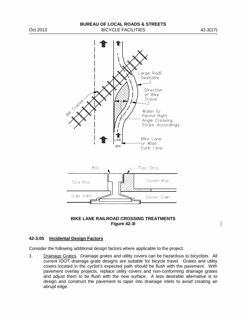
3. Crossing Angle. Bicyclists should be able to cross railroad tracks at or near a right angle to minimize the potential for the bicycle’s front wheel to be trapped in the flangeway. When the crossing angle is less than 45°, consider widening the outside lane, shoulder, or bicycle lane to improve the angle of approach (See Figure 42-3I). Where this is not practical, consider using commercially available compressible flangeway fillers to provide a smooth transition over the rails (See Figure 42-3I). Appropriate pavement striping in the widened area can guide users of the bike lane toward the safest alignment across the tracks.
4. Surface. The bicycle portion of the pavement surface should be at the same elevation as the top of the rails. Provide a bicycle-crossing surface that is consistent with the vehicular or bike path-crossing surface.
5. Visibility. Maximum visibility should be provided to improve the cyclist’s awareness of approaching trains. Post Railroad Advance Warning signs no less than 50 ft (15 m) in advance of the tracks.
6. Signing and Protection. Crossbuck signs shall be erected at the crossing. All signing should conform to ILMUTCD. The LPA should coordinate with the railroad to determine the need for flashing light signals and gates.
7. Coordination. Contact the railroad early in the development of the project. The ICC may also be involved with bike crossings adjacent to roadways.
BUREAU OF LOCAL ROADS & STREETS Oct 2013 BICYCLE FACILITIES 42-3(17)
BIKE LANE RAILROAD CROSSING TREATMENTS
Figure 42-3I
42-3.05 Incidental Design Factors
Consider the following additional design factors where applicable to the project.
1. Drainage Grates. Drainage grates and utility covers can be hazardous to bicyclists. All current IDOT drainage grate designs are suitable for bicycle travel. Grates and utility covers located in the cyclist’s expected path should be flush with the pavement. With pavement overlay projects, replace utility covers and non-conforming drainage grates and adjust them to be flush with the new surface. A less desirable alternative is to design and construct the pavement to taper into drainage inlets to avoid creating an abrupt edge.
BUREAU OF LOCAL ROADS & STREETS 42-3(18) BICYCLE FACILITIES Oct 2013 2. Bollards. If bollards are installed across a bike path where it intersects with a street,
provide an adequate clear zone between the bollards and the street.
3. Environmental Effects. Analysis of the environmental effects of bicycle accommodations should be accomplished and documented along with the environmental analysis for the associated highway project. When not part of a roadway project, bikeway projects may be processed as a Categorical Exclusion (CE) for federally funded projects.
4. Rumble Strips. Where rumble strips are placed across the traffic lane in rural areas to warn motorists of upcoming traffic controls, provide a minimum 3 ft (1.0 m) clear paved area on the paved portion of the shoulder to allow a bicyclist an opportunity to avoid the rumble strip. When rumble strips are installed in a paved shoulder which serves as a bicycle accommodation and the width of the paved shoulder is 6 ft (1.8 m) or less, the 8 in (200 mm) rumble strip design should used to minimize the impact to the accommodation.
42-3.06 Signing, Pavement Marking, and Traffic Control
Signing, pavement markings, and traffic control for bicycle facilities will be in accordance with the criteria presented in the ILMUTCD and applicable local ordinances. Signing and pavement markings are especially important at the approaches to intersections and at bike lane termini. Where a bike lane ends, bicyclists may be required to merge with motor vehicle traffic. Bicyclists should be encouraged with the appropriate signing and pavement markings to make lane changes in advance of the intersection. Not all bicycle accommodations or bikeways need to be or should be marked as bike routes. Generally, only low-volume roads, bike lanes and bicycle paths should be marked as designated bicycle facilities. The absence of a marked bicycle lane or any other traffic control devices shall not be construed to mean that bicyclists are not permitted to travel on that roadway. Bicycle routes should be marked if they meet the following criteria, are continuous, and are at least 1 mi (1.5 km) long:
• The route provides through and direct travel in bicycle-demand corridors.
• The route connects discontinuous segments of shared used paths, bike lanes, and/or other bike routes.
• An effort has been made to adjust traffic control devices (e.g., stop signs, signals) to give greater priority to bicyclists on the route, as opposed to alternative streets. This could include placement of bicycle-sensitive detectors where bicyclists are expected to stop.
• Street parking has been removed or restricted in areas of critical width to provide improved safety.
The following are some examples of what should not be marked:
• Wide curb lanes that provide intermittent access to businesses along the route, but provide no connection to another part of a bike route; and
• Any facility that does not meet minimum design criteria in the AASHTO publication Guide for the Development of Bicycle Facilities.
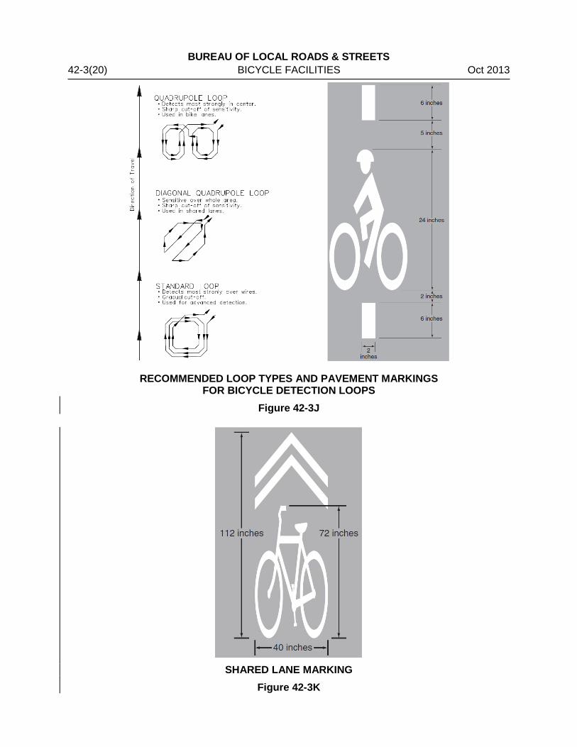
BUREAU OF LOCAL ROADS & STREETS Oct 2013 BICYCLE FACILITIES 42-3(19) However, short segments of a continuous bike route that do not meet minimum criteria may be marked if the user is adequately warned of the conditions. For example, where a roadway serves as a bikeway and intermittent restrictions on width exist, such as at narrow bridges, mark these obstructions with both signing and pavement markings to warn bicyclists and motorists of the hazards. At signalized intersections where frequent bicyclists need access to a green signal phase, a number of acceptable alternative methods are available including timed signals (where a cyclist must wait for the signal to change), traffic-actuated detectors, and push-button actuation. This opportunity (to access a green signal) should be provided where a marked bikeway crosses the project corridor. Other crossing locations to consider include potential bicycle travel from schools, parks, or other significant destinations described in Section 42-2. Traffic-actuated detection should be sensitive to bicycles and should be located in the bicyclist’s expected path, including left-turn lanes if necessary. Figure 42-3J shows three recommended loop types for bicycle detection, each with particular advantages, and a pavement-marking stencil used to designate where a bicyclist should stand to activate the detector loop. The following information on bicycle detection should be considered:
1. Quadrupole Loop Detectors. The quadrupole loop detector functions best in a bicycle path or lane situation. In such a situation, the expected position of a bicyclist can be easily predicted. This loop is less sensitive over its outer wire than over its center wires and is also relatively insensitive to motor vehicle traffic in neighboring lanes.
2. Diagonal Quadrupole Loop Detector. The diagonal quadrupole loop detector functions best in shared-roadway situations where the position of a bicycle cannot be easily predicted. This detector is equally sensitive over its entire width and is relatively insensitive to motor vehicle traffic in neighboring lanes.
Signal timing usually does not need to be lengthened to allow adequate time for bicycle crossing. The AASHTO publication Guide for the Development of Bicycle Facilities recommends calculating clearance intervals with a bicyclist’s speed of 10 mph (16 km/h) and a perception/reaction/braking time of 1.0 second. At extremely wide intersections, however, consider providing a median refuge area that is at least 6 ft (2 m) wide if signal timing would prohibit adequate crossing time. The shared lane marking (sharrow) shown in Figure 42-3K should be placed:
1. On highways with on-street parallel parking, at least 11 ft (3.4 m) from the face of curb, or edge of travelled way where there is no curb; or
2. On highways without on-street parallel parking, at least 4 ft (1.2 m) from the face of curb, or edge of travelled way where there is no curb.
Section 9C.07 of the ILMUTCD contains further guidance.
BUREAU OF LOCAL ROADS & STREETS 42-3(20) BICYCLE FACILITIES Oct 2013
RECOMMENDED LOOP TYPES AND PAVEMENT MARKINGS FOR BICYCLE DETECTION LOOPS
Figure 42-3J
SHARED LANE MARKING
Figure 42-3K

BUREAU OF LOCAL ROADS & STREETS Oct 2013 BICYCLE FACILITIES 42-4(1) 42-4 MAINTENANCE
Responsibility for maintenance of bike lane facilities should be determined and agreed upon during the planning process and should be included in the local agency funding agreement, when applicable.

BUREAU OF LOCAL ROADS & STREETS 42-4(2) BICYCLE FACILITIES Oct 2013

BUREAU OF LOCAL ROADS & STREETS Oct 2013 BICYCLE FACILITIES 42-5(1) 42-5 REFERENCES
1. Guide for the Development of Bicycle Facilities, AASHTO, 4th Edition, 2012. 2. Chapter 17, “Bicycle and Pedestrian Accommodation,” Bureau of Design and
Environment Manual, IDOT.

BUREAU OF LOCAL ROADS & STREETS 42-5(2) BICYCLE FACILITIES Oct 2013