chapter introduction to tcp/ip 3 - dginter.net · chapter 3 introduction to tcp/ip the following...
TRANSCRIPT

Chapter
3Introduction to TCP/IP
ThE FOLLOWING ICND1 ExAM TOPICS ARE COVERED IN ThIS ChAPTER:
u1 Operation of IP Data Networks
u■ Identify common applications and their impact on the network
u■ Describe the purpose and basic operation of the protocols in
the OSI and TCP/IP models.
u1 IP addressing (IPv4 / IPv6)
u■ Describe the operation and necessity of using private and
public IP addresses for IPv4 addressing

The Transmission Control Protocol/Internet Protocol (TCP/IP) suite was designed and implemented by the Department of Defense (DoD) to ensure and preserve data
integrity as well as maintain communications in the event of catastrophic war. So it follows that if designed and implemented correctly, a TCP/IP network can be a secure, dependable and resilient one. In this chapter, I’ll cover the protocols of TCP/IP, and throughout this book, you’ll learn how to create a solid TCP/IP network with Cisco routers and switches.
We’ll begin by exploring the DoD’s version of TCP/IP, then compare that version and its protocols with the OSI reference model that we discussed earlier.
Once you understand the protocols and processes used at the various levels of the DoD model, we’ll take the next logical step by delving into the world of IP addressing and the different classes of IP addresses used in networks today.
Subnetting is so vital, it will be covered in its own Chapter 4, “Easy Subnetting.”
Because having a good grasp of the various IPv4 address types is critical to understanding IP addressing, subnetting and variable length subnet masks (VLSMs), we’ll explore these key topics in detail, ending this chapter by discussing the various types of IPv4 addresses that you’ll need to have down for the exam.
I’m not going to cover Internet Protocol version 6 in this chapter because we’ll get into that later, in Chapter 14, “Internet Protocol Version 6 (IPv6).” And just so you know, you’ll simply see Internet Protocol version 4 written as just IP, rarely as IPv4.
To find up-to-the minute updates for this chapter, please see www.lammle.com/forum or the book’s web page at www.sybex.com.
Introducing TCP/IPTCP/IP is at the very core of all things networking, so I really want to ensure that you have a comprehensive and functional command of it. I’ll start by giving you the whole TCP/IP backstory, including its inception, and then move on to describe the important technical
TCP/IP and the DoD Model 89
goals as defined by its original architects. And of course I’ll include how TCP/IP compares to the theoretical OSI model.
A Brief History of TCP/IPTCP first came on the scene way back in 1973, and in 1978, it was divided into two dis-tinct protocols: TCP and IP. Later, in 1983, TCP/IP replaced the Network Control Protocol (NCP) and was authorized as the official means of data transport for anything connecting to ARPAnet, the Internet’s ancestor. The DoD’s Advanced Research Projects Agency (ARPA) created this ancient network way back in 1957 in a cold war reaction to the Soviet’s launch-ing of Sputnik. Also in 1983, ARPA was redubbed DARPA and divided into ARPAnet and MILNET until both were finally dissolved in 1990.
It may be counterintuitive, but most of the development work on TCP/IP happened at UC Berkeley in Northern California, where a group of scientists were simultaneously work-ing on the Berkeley version of UNIX, which soon became known as the Berkeley Software Distribution (BSD) series of UNIX versions. Of course, because TCP/IP worked so well, it was packaged into subsequent releases of BSD Unix and offered to other universities and institutions if they bought the distribution tape. So basically, BSD Unix bundled with TCP/IP began as shareware in the world of academia. As a result, it became the foundation for the tremendous success and unprecedented growth of today’s Internet as well as smaller, private and corporate intranets.
As usual, what started as a small group of TCP/IP aficionados evolved, and as it did, the US government created a program to test any new published standards and make sure they passed certain criteria. This was to protect TCP/IP’s integrity and to ensure that no developer changed anything too dramatically or added any proprietary features. It’s this very quality—this open-systems approach to the TCP/IP family of protocols—that sealed its popularity because this quality guarantees a solid connection between myriad hardware and software platforms with no strings attached.
TCP/IP and the DoD ModelThe DoD model is basically a condensed version of the OSI model that comprises four instead of seven layers:
uu Process/Application layer
uu Host-to-Host layer/or Transport
uu Internet layer
uu Network Access layer/or Link
Figure 3.1 offers a comparison of the DoD model and the OSI reference model. As you can see, the two are similar in concept, but each has a different number of layers with different names. Cisco may at times use different names for the same layer, such as both “Network Access” and “Link” used to describe the bottom layer.

90 Chapter 3 u Introduction to TCP/IP
F I Gu R E 3 .1 The DoD and OSI models
Application
OSI Model
SessionPresentation
Transport
Network
Data LinkPhysical
Process/Application
DoD Model
Host-to-Host
Internet
NetworkAccess
When the different protocols in the IP stack are discussed, the layers of the OSI and DoD models are interchangeable. In other words, be prepared for the exam objectives to call the Host-to-Host layer the Transport layer!
A vast array of protocols join forces at the DoD model’s Process/Application layer. These processes integrate the various activities and duties spanning the focus of the OSI’s corresponding top three layers (Application, Presentation, and Session). We’ll focus on a few of the most important applications found in the CCNA objectives. In short, the Process/Application layer defines protocols for node-to-node application communication and controls user-interface specifications.
The Host-to-Host layer parallels the functions of the OSI’s Transport layer, defining protocols for setting up the level of transmission service for applications. It tackles issues like creating reliable end-to-end communication and ensuring the error-free delivery of data. It handles packet sequencing and maintains data integrity.
The Internet layer corresponds to the OSI’s Network layer, designating the protocols relating to the logical transmission of packets over the entire network. It takes care of the addressing of hosts by giving them an IP (Internet Protocol) address and handles the routing of packets among multiple networks.
At the bottom of the DoD model, the Network Access layer implements the data exchange between the host and the network. The equivalent of the Data Link and Physical layers of the OSI model, the Network Access layer oversees hardware addressing and defines protocols for the physical transmission of data. The reason TCP/IP became so popular is because there were no set physical layer specifications, so it could run on any existing or future physical network!
The DoD and OSI models are alike in design and concept and have similar functions in similar layers. Figure 3.2 shows the TCP/IP protocol suite and how its protocols relate to the DoD model layers.
In the following sections, we will look at the different protocols in more detail, beginning with those found at the Process/Application layer.

TCP/IP and the DoD Model 91
F I Gu R E 3 . 2 The TCP/IP protocol suite
DoD Model
TelnetTFTP
FTPSMTP
LPDNFS
SNMPX Window
Process/Application
Host-to-Host
ICMP ARP RARPIP
Internet
NetworkAccess
TCP UDP
Ethernet FastEthernet
GigabitEthernet
10 GigEthernet
The Process/Application Layer ProtocolsComing up, I’ll describe the different applications and services typically used in IP networks, and although there are many more protocols defined here, we’ll focus in on the protocols most relevant to the CCNA objectives. Here’s a list of the protocols and applications we’ll cover in this section:
uu Telnet
uu SSH
uu FTP
uu TFTP
uu SNMP
uu HTTP
uu HTTPS
uu NTP
uu DNS
uu DHCP/BootP
TelnetTelnet was one of the first Internet standards, developed in 1969, and is the chameleon of protocols—its specialty is terminal emulation. It allows a user on a remote client machine, called the Telnet client, to access the resources of another machine, the Telnet server, in order to access a command-line interface. Telnet achieves this by pulling a fast one on the Telnet server and making the client machine appear as though it were a terminal directly attached to the local network. This projection is actually a software image—a virtual terminal that can interact with the chosen remote host. A drawback is that there are no encryption techniques

92 Chapter 3 u Introduction to TCP/IP
available within the Telnet protocol, so everything must be sent in clear text, including pass-words! Figure 3.3 shows an example of a Telnet client trying to connect to a Telnet server.
F I Gu R E 3 . 3 Telnet
>telnet 1.1.1.2
Can I have access toyour command line?
Okay! Configure me!
I’ll send everything inclear text, including
passwords...Good, because I can’t
do encryption!
These emulated terminals are of the text-mode type and can execute defined procedures such as displaying menus that give users the opportunity to choose options and access the applications on the duped server. Users begin a Telnet session by running the Telnet client software and then logging into the Telnet server. Telnet uses an 8-bit, byte-oriented data connection over TCP, which makes it very thorough. It’s still in use today because it is so simple and easy to use, with very low overhead, but again, with everything sent in clear text, it’s not recommended in production.
Secure Shell (SSH)Secure Shell (SSH) protocol sets up a secure session that’s similar to Telnet over a standard TCP/IP connection and is employed for doing things like logging into systems, running programs on remote systems, and moving files from one system to another. And it does all of this while maintaining an encrypted connection. Figure 3.4 shows a SSH client trying to connect to a SSH server. The client must send the data encrypted!
You can think of it as the new-generation protocol that’s now used in place of the anti-quated and very unused rsh and rlogin—even Telnet.
File Transfer Protocol (FTP)File Transfer Protocol (FTP) actually lets us transfer files, and it can accomplish this between any two machines using it. But FTP isn’t just a protocol; it’s also a program. Operating as a protocol, FTP is used by applications. As a program, it’s employed by users to perform file tasks by hand. FTP also allows for access to both directories and files and can accomplish certain types of directory operations, such as relocating into different ones (Figure 3.5).
But accessing a host through FTP is only the first step. Users must then be subjected to an authentication login that’s usually secured with passwords and usernames implemented by system administrators to restrict access. You can get around this somewhat by adopting the username anonymous, but you’ll be limited in what you’ll be able to access.

TCP/IP and the DoD Model 93
F I Gu R E 3 . 4 Secure Shell
>ssh [email protected]
Can I have access toyour command line?
I accept onlyencrypted data!
Here is my encryptedusername, password andkey: a@#$alskdjf2H!Vm34
Here is my response:eSgkh2g42#$!@!#!$kjka12s
F I Gu R E 3 .5 FTP
I want to get a file!
Which one?
I don’t know, what doyou have available?
No problem! Here is mydirectory of available files!
Even when employed by users manually as a program, FTP’s functions are limited to listing and manipulating directories, typing file contents, and copying files between hosts. It can’t execute remote files as programs.
Trivial File Transfer Protocol (TFTP)Trivial File Transfer Protocol (TFTP) is the stripped-down, stock version of FTP, but it’s the protocol of choice if you know exactly what you want and where to find it because it’s fast and so easy to use!
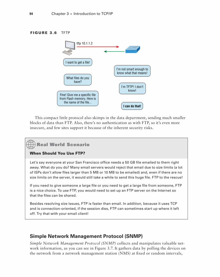
But TFTP doesn’t offer the abundance of functions that FTP does because it has no directory-browsing abilities, meaning that it can only send and receive files (Figure 3.6). Still, it’s heavily used for managing file systems on Cisco devices, as I’ll show you in Chapter 7, “Managing and Troubleshooting a Cisco Internetwork.”
94 Chapter 3 u Introduction to TCP/IP
F I Gu R E 3 .6 TFTP
tftp 10.1.1.2
I want to get a file!
I’m not smart enough toknow what that means!
What files do youhave?
I’m TFTP! I don’tknow!
Fine! Give me a specific filefrom Flash memory. Here is
the name of the file...I can do that!
This compact little protocol also skimps in the data department, sending much smaller blocks of data than FTP. Also, there’s no authentication as with FTP, so it’s even more insecure, and few sites support it because of the inherent security risks.
When Should You use FTP?
Let’s say everyone at your San Francisco office needs a 50 GB file emailed to them right away. What do you do? Many email servers would reject that email due to size limits (a lot of ISPs don’t allow files larger than 5 MB or 10 MB to be emailed) and, even if there are no size limits on the server, it would still take a while to send this huge file. FTP to the rescue!
If you need to give someone a large file or you need to get a large file from someone, FTP is a nice choice. To use FTP, you would need to set up an FTP server on the Internet so that the files can be shared.
Besides resolving size issues, FTP is faster than email. In addition, because it uses TCP and is connection-oriented, if the session dies, FTP can sometimes start up where it left off. Try that with your email client!
Simple Network Management Protocol (SNMP)Simple Network Management Protocol (SNMP) collects and manipulates valuable net-work information, as you can see in Figure 3.7. It gathers data by polling the devices on the network from a network management station (NMS) at fixed or random intervals,

TCP/IP and the DoD Model 95
requiring them to disclose certain information, or even asking for certain information from the device. In addition, network devices can inform the NMS station about prob-lems as they occur so the network administrator is alerted.
F I Gu R E 3 .7 SNMP
MY FAN DIED! I’M BURNINGUP!! UGH!!
OKAY! I’ll sound the alarm!
NMS Station
When all is well, SNMP receives something called a baseline—a report delimiting the operational traits of a healthy network. This protocol can also stand as a watchdog over the network, quickly notifying managers of any sudden turn of events. These network watchdogs are called agents, and when aberrations occur, agents send an alert called a trap to the management station.
SNMP Versions 1, 2, and 3
SNMP versions 1 and 2 are pretty much obsolete. This doesn’t mean you won’t see them in a network now and then, but you’ll only come across v1 rarely, if ever. SNMPv2 provided improvements, especially in performance. But one of the best additions was called GETBULK, which allowed a host to retrieve a large amount of data at once. Even so, v2 never really caught on in the networking world and SNMPv3 is now the standard. Unlike v1, which used only UDP, v3 uses both TCP and UDP and added even more secu-rity, message integrity, authentication, and encryption.
Hypertext Transfer Protocol (HTTP)All those snappy websites comprising a mélange of graphics, text, links, ads and so on rely on the Hypertext Transfer Protocol (HTTP) to make it all possible (Figure 3.8). It’s used to manage communications between web browsers and web servers and opens the right resource when you click a link, wherever that resource may actually reside.
In order for a browser to display a web page, it must find the exact server that has the right web page, plus the exact details that identify the information requested. This informa-tion must be then be sent back to the browser. Nowadays, it’s highly doubtful that a web server would have only one page to display!

96 Chapter 3 u Introduction to TCP/IP
F I Gu R E 3 . 8 HTTP
Okay! Here is the web page forwww.lammle.com
I want to get some awesomeCisco training! I want URL
www.lammle.com!
http://www.Lammle.com
Your browser can understand what you need when you enter a Uniform Resource Locator (URL), which we usually refer to as a web address, e.g. http://www.lammle.com/forum and http://www.lammle.com/blog.
So basically, each URL defines the protocol used to transfer data, the name of the server, and the particular web page on that server.
Hypertext Transfer Protocol Secure (HTTPS)Hypertext Transfer Protocol Secure (HTTPS) is also known as Secure Hypertext Transfer Protocol. It uses Secure Sockets Layer (SSL). Sometimes you’ll see it referred to as SHTTP or S-HTTP, which were slightly different protocols, but since Microsoft supported HTTPS, it became the de facto standard for securing web communication. But no matter—as indicated, it’s a secure version of HTTP that arms you with a whole bunch of security tools for keeping transactions between a web browser and a server secure.
It’s what your browser needs to fill out forms, sign in, authenticate, and encrypt an HTTP message when you do things online like make a reservation, access your bank, or buy something.
Network Time Protocol (NTP)Kudos to Professor David Mills of the University of Delaware for coming up with this handy protocol that’s used to synchronize the clocks on our computers to one standard time source (typically, an atomic clock). Network Time Protocol (NTP) works by synchronizing devices to ensure that all computers on a given network agree on the time (Figure 3.9).
This may sound pretty simple, but it’s very important because so many of the transac-tions done today are time and date stamped. Think about databases—a server can get messed up pretty badly and even crash if it’s out of sync with the machines connected to it by even mere seconds! You can’t have a transaction entered by a machine at, say, 1:50 a.m. when the server records that transaction as having occurred at 1:45 a.m. So basically, NTP works to prevent a “back to the future sans DeLorean” scenario from bringing down the network—very important indeed!
I’ll tell you a lot more about NTP in Chapter 7, including how to configure this protocol in a Cisco environment.

TCP/IP and the DoD Model 97
F I Gu R E 3 . 9 NTP
I’m connected to an atomicclock on the Internet – here is
the exact time and date!
I have some errors to report butI need to record them with the
correct time and date!
What is the exact time?
NTP Server
Domain Name Service (DNS)Domain Name Service (DNS) resolves hostnames—specifically, Internet names, such as www .lammle.com. But you don’t have to actually use DNS. You just type in the IP address of any device you want to communicate with and find the IP address of a URL by using the Ping program. For example, >ping www.cisco.com will return the IP address resolved by DNS.
An IP address identifies hosts on a network and the Internet as well, but DNS was designed to make our lives easier. Think about this: What would happen if you wanted to move your web page to a different service provider? The IP address would change and no one would know what the new one was. DNS allows you to use a domain name to specify an IP address. You can change the IP address as often as you want and no one will know the difference.
To resolve a DNS address from a host, you’d typically type in the URL from your favor-ite browser, which would hand the data to the Application layer interface to be transmitted on the network. The application would look up the DNS address and send a UDP request to your DNS server to resolve the name (Figure 3.10).
F I Gu R E 3 .10 DNS
What is the address forLammle.com?
I don’t know. Let me checkwith another server!
I know the answer!DNS Root Server
Lammle.com is198.1.78.115Get me to 198.1.78.115 ASAP!
DNS Server Lammle.com is:198.1.78.115
1 2
5 4 3

98 Chapter 3 u Introduction to TCP/IP
If your first DNS server doesn’t know the answer to the query, then the DNS server forwards a TCP request to its root DNS server. Once the query is resolved, the answer is transmitted back to the originating host, which means the host can now request the information from the correct web server.
DNS is used to resolve a fully qualified domain name (FQDN)—for example, www.lammle .com or todd.lammle.com. An FQDN is a hierarchy that can logically locate a system based on its domain identifier.
If you want to resolve the name todd, you either must type in the FQDN of todd.lammle .com or have a device such as a PC or router add the suffix for you. For example, on a Cisco router, you can use the command ip domain-name lammle.com to append each request with the lammle.com domain. If you don’t do that, you’ll have to type in the FQDN to get DNS to resolve the name.
An important thing to remember about DNS is that if you can ping a device with an IP address but cannot use its FQDN, then you might have some type of DNS configuration failure.
Dynamic Host Configuration Protocol (DHCP)/Bootstrap Protocol (BootP)Dynamic Host Configuration Protocol (DHCP) assigns IP addresses to hosts. It allows for easier administration and works well in small to very large network environments. Many types of hardware can be used as a DHCP server, including a Cisco router.
DHCP differs from BootP in that BootP assigns an IP address to a host but the host’s hardware address must be entered manually in a BootP table. You can think of DHCP as a dynamic BootP. But remember that BootP is also used to send an operating system that a host can boot from. DHCP can’t do that.
But there’s still a lot of information a DHCP server can provide to a host when the host is requesting an IP address from the DHCP server. Here’s a list of the most common types of information a DHCP server can provide:
uu IP address
uu Subnet mask
uu Domain name
uu Default gateway (routers)
uu DNS server address
uu WINS server address
A client that sends out a DHCP Discover message in order to receive an IP address sends out a broadcast at both layer 2 and layer 3.
uu The layer 2 broadcast is all Fs in hex, which looks like this: ff:ff:ff:ff:ff:ff.
uu The layer 3 broadcast is 255.255.255.255, which means all networks and all hosts.
TCP/IP and the DoD Model 99
DHCP is connectionless, which means it uses User Datagram Protocol (UDP) at the Transport layer, also known as the Host-to-Host layer, which we’ll talk about later.
Seeing is believing, so here’s an example of output from my analyzer showing the layer 2 and layer 3 broadcasts:
Ethernet II, Src: 0.0.0.0 (00:0b:db:99:d3:5e),Dst: Broadcast(ff:ff:ff:ff:ff:ff)Internet Protocol, Src: 0.0.0.0 (0.0.0.0),Dst: 255.255.255.255(255.255.255.255)
The Data Link and Network layers are both sending out “all hands” broadcasts saying, “Help—I don’t know my IP address!”
DHCP will be discussed in more detail, including configuration on a Cisco router and switch, in Chapter 7 and Chapter 8, “IP Routing.”
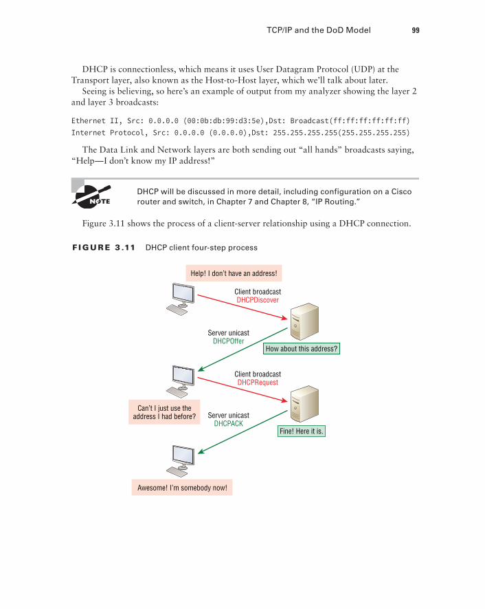
Figure 3.11 shows the process of a client-server relationship using a DHCP connection.
F I Gu R E 3 .11 DHCP client four-step process
Help! I don’t have an address!
Client broadcastDHCPDiscover
Server unicastDHCPOffer
How about this address?
Can’t I just use theaddress I had before?
Awesome! I’m somebody now!
Client broadcastDHCPRequest
Server unicastDHCPACK
Fine! Here it is.

100 Chapter 3 u Introduction to TCP/IP
This is the four-step process a client takes to receive an IP address from a DHCP server:
1. The DHCP client broadcasts a DHCP Discover message looking for a DHCP server (Port 67).
2. The DHCP server that received the DHCP Discover message sends a layer 2 unicast DHCP Offer message back to the host.
3. The client then broadcasts to the server a DHCP Request message asking for the offered IP address and possibly other information.
4. The server finalizes the exchange with a unicast DHCP Acknowledgment message.
DHCP Conflicts
A DHCP address conflict occurs when two hosts use the same IP address. This sounds bad, and it is! We’ll never even have to discuss this problem once we get to the chapter on IPv6!
During IP address assignment, a DHCP server checks for conflicts using the Ping program to test the availability of the address before it’s assigned from the pool. If no host replies, then the DHCP server assumes that the IP address is not already allocated. This helps the server know that it’s providing a good address, but what about the host? To provide extra protection against that terrible IP conflict issue, the host can broadcast for its own address!
A host uses something called a gratuitous ARP to help avoid a possible duplicate address. The DHCP client sends an ARP broadcast out on the local LAN or VLAN using its newly assigned address to solve conflicts before they occur.
So, if an IP address conflict is detected, the address is removed from the DHCP pool (scope), and it’s really important to remember that the address will not be assigned to a host until the administrator resolves the conflict by hand!
Please see Chapter 8 to check out a DHCP configuration on a Cisco router and also to find out what happens when a DHCP client is on one side of a router but the DHCP server is on the other side on a different network!
Automatic Private IP Addressing (APIPA)Okay, so what happens if you have a few hosts connected together with a switch or hub and you don’t have a DHCP server? You can add IP information by hand, known as static IP addressing, but later Windows operating systems provide a feature called Automatic Private IP Addressing (APIPA). With APIPA, clients can automatically self-configure an IP address and subnet mask—basic IP information that hosts use to communicate—when a DHCP server isn’t available. The IP address range for APIPA is 169.254.0.1 through 169.254.255.254. The client also configures itself with a default Class B subnet mask of 255.255.0.0.
But when you’re in your corporate network working and you have a DHCP server run-ning, and your host shows that it’s using this IP address range, it means that either your DHCP client on the host is not working or the server is down or can’t be reached due to

TCP/IP and the DoD Model 101
some network issue. Believe me—I don’t know anyone who’s seen a host in this address range and has been happy about it!
Now, let’s take a look at the Transport layer, or what the DoD calls the Host-to-Host layer.
The Host-to-host Layer ProtocolsThe main purpose of the Host-to-Host layer is to shield the upper-layer applications from the complexities of the network. This layer says to the upper layer, “Just give me your data stream, with any instructions, and I’ll begin the process of getting your information ready to send.”
Coming up, I’ll introduce you to the two protocols at this layer:
uu Transmission Control Protocol (TCP)
uu User Datagram Protocol (UDP)
In addition, we’ll look at some of the key host-to-host protocol concepts, as well as the port numbers.
Remember, this is still considered layer 4, and Cisco really likes the way layer 4 can use acknowledgments, sequencing, and flow control.
Transmission Control Protocol (TCP)Transmission Control Protocol (TCP) takes large blocks of information from an applica-tion and breaks them into segments. It numbers and sequences each segment so that the destination’s TCP stack can put the segments back into the order the application intended. After these segments are sent on the transmitting host, TCP waits for an acknowledgment of the receiving end’s TCP virtual circuit session, retransmitting any segments that aren’t acknowledged.
Before a transmitting host starts to send segments down the model, the sender’s TCP stack contacts the destination’s TCP stack to establish a connection. This creates a virtual circuit, and this type of communication is known as connection-oriented. During this ini-tial handshake, the two TCP layers also agree on the amount of information that’s going to be sent before the recipient’s TCP sends back an acknowledgment. With everything agreed upon in advance, the path is paved for reliable communication to take place.
TCP is a full-duplex, connection-oriented, reliable, and accurate protocol, but estab-lishing all these terms and conditions, in addition to error checking, is no small task. TCP is very complicated, and so not surprisingly, it’s costly in terms of network overhead. And since today’s networks are much more reliable than those of yore, this added reliability is often unnecessary. Most programmers use TCP because it removes a lot of programming work, but for real-time video and VoIP, User Datagram Protocol (UDP) is often better because using it results in less overhead.

102 Chapter 3 u Introduction to TCP/IP
TCP Segment Format
Since the upper layers just send a data stream to the protocols in the Transport layers, I’ll use Figure 3.12 to demonstrate how TCP segments a data stream and prepares it for the Internet layer. When the Internet layer receives the data stream, it routes the segments as packets through an internetwork. The segments are handed to the receiving host’s Host-to-Host layer protocol, which rebuilds the data stream for the upper-layer applications or protocols.
F I Gu R E 3 .12 TCP segment format
4-bitheaderlength
Reserved Flags 16-bit window size
Host-to-HostHost-to-Host
16-bit destination port16-bit source port
16-bit urgent pointer16-bit TCP checksum
32-bit sequence number32-Bit Acknowledgment Number
OptionsData
Figure 3.12 shows the TCP segment format and shows the different fields within the TCP header. This isn’t important to memorize for the Cisco exam objectives, but you need to understand it well because it’s really good foundational information.
The TCP header is 20 bytes long, or up to 24 bytes with options. You need to understand what each field in the TCP segment is in order to build a strong educational foundation:
Source port This is the port number of the application on the host sending the data, which I’ll talk about more thoroughly a little later in this chapter.
Destination port This is the port number of the application requested on the destina-tion host.
Sequence number A number used by TCP that puts the data back in the correct order or retransmits missing or damaged data during a process called sequencing.
Acknowledgment number The value is the TCP octet that is expected next.
Header length The number of 32-bit words in the TCP header, which indicates where the data begins. The TCP header (even one including options) is an integral number of 32 bits in length.
Reserved Always set to zero.
Code bits/flags Controls functions used to set up and terminate a session.
Window The window size the sender is willing to accept, in octets.
Checksum The cyclic redundancy check (CRC), used because TCP doesn’t trust the lower layers and checks everything. The CRC checks the header and data fields.

TCP/IP and the DoD Model 103
Urgent A valid field only if the Urgent pointer in the code bits is set. If so, this value indicates the offset from the current sequence number, in octets, where the segment of non-urgent data begins.
Options May be 0, meaning that no options have to be present, or a multiple of 32 bits. However, if any options are used that do not cause the option field to total a multiple of 32 bits, padding of 0s must be used to make sure the data begins on a 32-bit boundary. These boundaries are known as words.
Data Handed down to the TCP protocol at the Transport layer, which includes the upper-layer headers.
Let’s take a look at a TCP segment copied from a network analyzer:
TCP - Transport Control Protocol Source Port: 5973 Destination Port: 23 Sequence Number: 1456389907 Ack Number: 1242056456 Offset: 5 Reserved: %000000 Code: %011000 Ack is valid Push Request Window: 61320 Checksum: 0x61a6 Urgent Pointer: 0 No TCP Options TCP Data Area: vL.5.+.5.+.5.+.5 76 4c 19 35 11 2b 19 35 11 2b 19 35 11 2b 19 35 +. 11 2b 19Frame Check Sequence: 0x0d00000f
Did you notice that everything I talked about earlier is in the segment? As you can see from the number of fields in the header, TCP creates a lot of overhead. Again, this is why application developers may opt for efficiency over reliability to save overhead and go with UDP instead. It’s also defined at the Transport layer as an alternative to TCP.
User Datagram Protocol (UDP)User Datagram Protocol (UDP) is basically the scaled-down economy model of TCP, which is why UDP is sometimes referred to as a thin protocol. Like a thin person on a park bench, a thin protocol doesn’t take up a lot of room—or in this case, require much bandwidth on a network.
104 Chapter 3 u Introduction to TCP/IP
UDP doesn’t offer all the bells and whistles of TCP either, but it does do a fabulous job of transporting information that doesn’t require reliable delivery, using far less network resources. (UDP is covered thoroughly in Request for Comments 768.)
So clearly, there are times that it’s wise for developers to opt for UDP rather than TCP, one of them being when reliability is already taken care of at the Process/Application layer. Network File System (NFS) handles its own reliability issues, making the use of TCP both impractical and redundant. But ultimately, it’s up to the application developer to opt for using UDP or TCP, not the user who wants to transfer data faster!
UDP does not sequence the segments and does not care about the order in which the seg-ments arrive at the destination. UDP just sends the segments off and forgets about them. It doesn’t follow through, check up on them, or even allow for an acknowledgment of safe arrival—complete abandonment. Because of this, it’s referred to as an unreliable protocol. This does not mean that UDP is ineffective, only that it doesn’t deal with reliability issues at all.
Furthermore, UDP doesn’t create a virtual circuit, nor does it contact the destination before delivering information to it. Because of this, it’s also considered a connectionless protocol. Since UDP assumes that the application will use its own reliability method, it doesn’t use any itself. This presents an application developer with a choice when running the Internet Protocol stack: TCP for reliability or UDP for faster transfers.
It’s important to know how this process works because if the segments arrive out of order, which is commonplace in IP networks, they’ll simply be passed up to the next layer in whatever order they were received. This can result in some seriously garbled data! On the other hand, TCP sequences the segments so they get put back together in exactly the right order, which is something UDP just can’t do.
UDP Segment Format
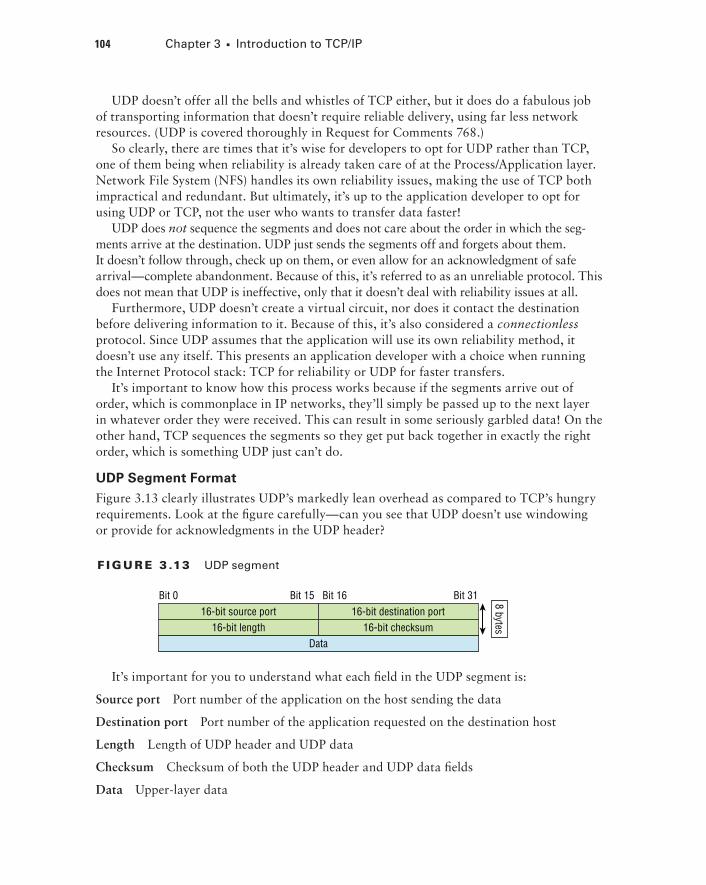
Figure 3.13 clearly illustrates UDP’s markedly lean overhead as compared to TCP’s hungry requirements. Look at the figure carefully—can you see that UDP doesn’t use windowing or provide for acknowledgments in the UDP header?
F I Gu R E 3 .13 UDP segment
16-bit destination port16-bit source portBit 31Bit 15Bit 0 Bit 16
16-bit checksum16-bit lengthData
8 bytes
It’s important for you to understand what each field in the UDP segment is:
Source port Port number of the application on the host sending the data
Destination port Port number of the application requested on the destination host
Length Length of UDP header and UDP data
Checksum Checksum of both the UDP header and UDP data fields
Data Upper-layer data

TCP/IP and the DoD Model 105
UDP, like TCP, doesn’t trust the lower layers and runs its own CRC. Remember that the Frame Check Sequence (FCS) is the field that houses the CRC, which is why you can see the FCS information.
The following shows a UDP segment caught on a network analyzer:
UDP - User Datagram Protocol Source Port: 1085 Destination Port: 5136 Length: 41 Checksum: 0x7a3c UDP Data Area: ..Z......00 01 5a 96 00 01 00 00 00 00 00 11 0000 00...C..2._C._C 2e 03 00 43 02 1e 32 0a 00 0a 00 80 43 00 80Frame Check Sequence: 0x00000000
Notice that low overhead! Try to find the sequence number, ack number, and window size in the UDP segment. You can’t because they just aren’t there!
Key Concepts of Host-to-Host ProtocolsSince you’ve now seen both a connection-oriented (TCP) and connectionless (UDP) protocol in action, it’s a good time to summarize the two here. Table 3.1 highlights some of the key concepts about these two protocols for you to memorize.
TA B LE 3 .1 Key features of TCP and UDP
TCP UDP
Sequenced Unsequenced
Reliable Unreliable
Connection-oriented Connectionless
Virtual circuit Low overhead
Acknowledgments No acknowledgment
Windowing flow control No windowing or flow control of any type
And if all this isn’t quite clear yet, a telephone analogy will really help you understand how TCP works. Most of us know that before you speak to someone on a phone, you must first establish a connection with that other person no matter where they are. This is akin to establishing a virtual circuit with the TCP protocol. If you were giving someone important

106 Chapter 3 u Introduction to TCP/IP
information during your conversation, you might say things like, “You know? or “Did you get that?” Saying things like this is a lot like a TCP acknowledgment—it’s designed to get you verification. From time to time, especially on mobile phones, people ask, “Are you still there?” People end their conversations with a “Goodbye” of some kind, putting closure on the phone call, which you can think of as tearing down the virtual circuit that was created for your communication session. TCP performs these types of functions.
Conversely, using UDP is more like sending a postcard. To do that, you don’t need to con-tact the other party first, you simply write your message, address the postcard, and send it off. This is analogous to UDP’s connectionless orientation. Since the message on the postcard is probably not a matter of life or death, you don’t need an acknowledgment of its receipt. Similarly, UDP does not involve acknowledgments.
Let’s take a look at another figure, one that includes TCP, UDP, and the applications associated to each protocol: Figure 3.14 (discussed in the next section).
F I Gu R E 3 .14 Port numbers for TCP and UDP
FTP Telnet POP3 DNS TFTP BootPS
TCP UDP
Applicationlayer
Port numbersTransport
layer
21 23 110 53 69 67
Port NumbersTCP and UDP must use port numbers to communicate with the upper layers because these are what keep track of different conversations crossing the network simultaneously. Originating-source port numbers are dynamically assigned by the source host and will equal some number starting at 1024. Port number 1023 and below are defined in RFC 3232 (or just see www.iana.org), which discusses what we call well-known port numbers.
Virtual circuits that don’t use an application with a well-known port number are assigned port numbers randomly from a specific range instead. These port numbers identify the source and destination application or process in the TCP segment.
The Requests for Comments (RFCs) form a series of notes about the Internet (originally the ARPAnet) began in 1969. These notes discuss many aspects of computer communication, focusing on networking pro-tocols, procedures, programs, and concepts; but they also include meet-ing notes, opinions, and sometimes even humor. You can find the RFCs by visiting www.iana.org.

TCP/IP and the DoD Model 107
Figure 3.14 illustrates how both TCP and UDP use port numbers. I’ll cover the different port numbers that can be used next:
uu Numbers below 1024 are considered well-known port numbers and are defined in RFC 3232.
uu Numbers 1024 and above are used by the upper layers to set up sessions with other hosts and by TCP and UDP to use as source and destination addresses in the segment.
TCP Session: Source Port
Let’s take a minute to check out analyzer output showing a TCP session I captured with my analyzer software session now:
TCP - Transport Control Protocol Source Port: 5973 Destination Port: 23 Sequence Number: 1456389907 Ack Number: 1242056456 Offset: 5 Reserved: %000000 Code: %011000 Ack is valid Push Request Window: 61320 Checksum: 0x61a6 Urgent Pointer: 0 No TCP Options TCP Data Area: vL.5.+.5.+.5.+.5 76 4c 19 35 11 2b 19 35 11 2b 19 35 11 2b 19 35 +. 11 2b 19Frame Check Sequence: 0x0d00000f
Notice that the source host makes up the source port, which in this case is 5973. The destination port is 23, which is used to tell the receiving host the purpose of the intended connection (Telnet).
By looking at this session, you can see that the source host makes up the source port by using numbers from 1024 to 65535. But why does the source make up a port number? To differentiate between sessions with different hosts because how would a server know where information is coming from if it didn’t have a different number from a sending host? TCP and the upper layers don’t use hardware and logical addresses to understand the sending host’s address as the Data Link and Network layer protocols do. Instead, they use port numbers.

108 Chapter 3 u Introduction to TCP/IP
TCP Session: Destination Port
You’ll sometimes look at an analyzer and see that only the source port is above 1024 and the destination port is a well-known port, as shown in the following trace:
TCP - Transport Control Protocol Source Port: 1144 Destination Port: 80 World Wide Web HTTP Sequence Number: 9356570 Ack Number: 0 Offset: 7 Reserved: %000000 Code: %000010 Synch Sequence Window: 8192 Checksum: 0x57E7 Urgent Pointer: 0 TCP Options: Option Type: 2 Maximum Segment Size Length: 4 MSS: 536 Option Type: 1 No Operation Option Type: 1 No Operation Option Type: 4 Length: 2 Opt Value: No More HTTP DataFrame Check Sequence: 0x43697363
And sure enough, the source port is over 1024, but the destination port is 80, indicating an HTTP service. The server, or receiving host, will change the destination port if it needs to.
In the preceding trace, a “SYN” packet is sent to the destination device. This Synch (as shown in the output) sequence is what’s used to inform the remote destination device that it wants to create a session.
TCP Session: Syn Packet Acknowledgment
The next trace shows an acknowledgment to the syn packet:
TCP - Transport Control Protocol Source Port: 80 World Wide Web HTTP Destination Port: 1144 Sequence Number: 2873580788 Ack Number: 9356571 Offset: 6
TCP/IP and the DoD Model 109
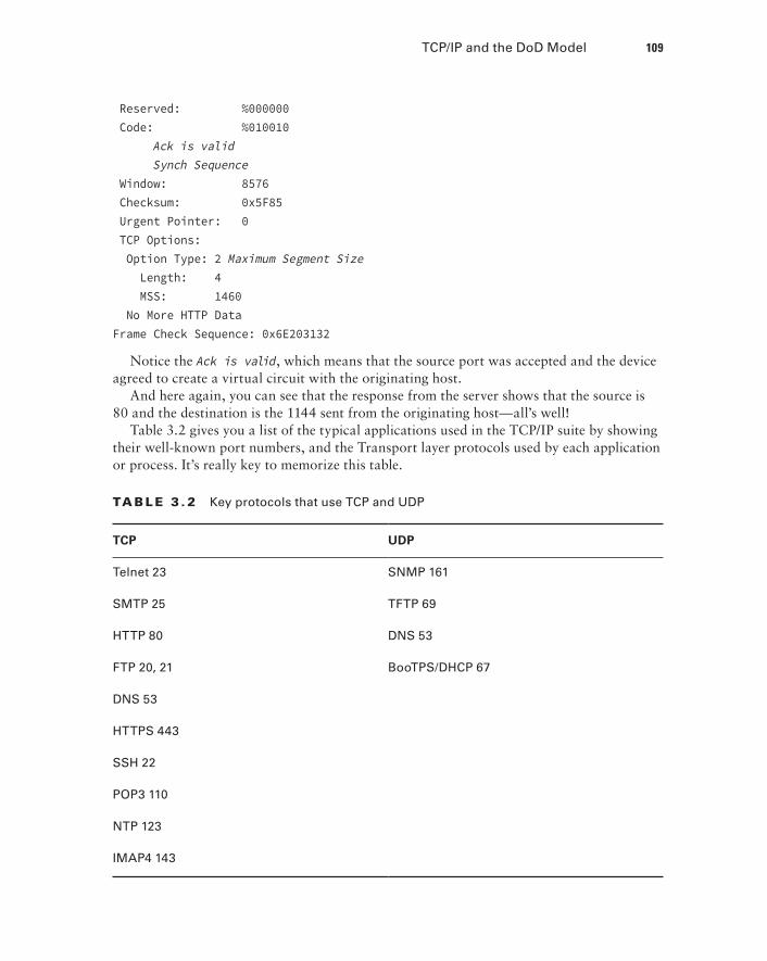
Reserved: %000000 Code: %010010 Ack is valid Synch Sequence Window: 8576 Checksum: 0x5F85 Urgent Pointer: 0 TCP Options: Option Type: 2 Maximum Segment Size Length: 4 MSS: 1460 No More HTTP DataFrame Check Sequence: 0x6E203132
Notice the Ack is valid, which means that the source port was accepted and the device agreed to create a virtual circuit with the originating host.
And here again, you can see that the response from the server shows that the source is 80 and the destination is the 1144 sent from the originating host—all’s well!
Table 3.2 gives you a list of the typical applications used in the TCP/IP suite by showing their well-known port numbers, and the Transport layer protocols used by each application or process. It’s really key to memorize this table.
TA B LE 3 . 2 Key protocols that use TCP and UDP
TCP UDP
Telnet 23 SNMP 161
SMTP 25 TFTP 69
HTTP 80 DNS 53
FTP 20, 21 BooTPS/DHCP 67
DNS 53
HTTPS 443
SSH 22
POP3 110
NTP 123
IMAP4 143

110 Chapter 3 u Introduction to TCP/IP
Notice that DNS uses both TCP and UDP. Whether it opts for one or the other depends on what it’s trying to do. Even though it’s not the only application that can use both proto-cols, it’s certainly one that you should make sure to remember in your studies.
What makes TCP reliable is sequencing, acknowledgments, and flow con-trol (windowing). UDP does not have reliability.
Okay—I want to discuss one more item before we move down to the Internet layer—session multiplexing. Session multiplexing is used by both TCP and UDP and basically allows a single computer, with a single IP address, to have multiple sessions occurring simultaneously. Say you go to www.lammle.com and are browsing and then you click a link to another page. Doing this opens another session to your host. Now you go to www .lammle.com/forum from another window and that site opens a window as well. Now you have three sessions open using one IP address because the Session layer is sorting the separate request based on the Transport layer port number. This is the job of the Session layer: to keep application layer data separate!
The Internet Layer ProtocolsIn the DoD model, there are two main reasons for the Internet layer’s existence: routing and providing a single network interface to the upper layers.
None of the other upper- or lower-layer protocols have any functions relating to routing—that complex and important task belongs entirely to the Internet layer. The Internet layer’s second duty is to provide a single network interface to the upper-layer protocols. Without this layer, application programmers would need to write “hooks” into every one of their applications for each different Network Access protocol. This would not only be a pain in the neck, but it would lead to different versions of each application—one for Ethernet, another one for wireless, and so on. To prevent this, IP provides one single network interface for the upper-layer protocols. With that mission accomplished, it’s then the job of IP and the various Network Access protocols to get along and work together.
All network roads don’t lead to Rome—they lead to IP. And all the other protocols at this layer, as well as all those at the upper layers, use it. Never forget that. All paths through the DoD model go through IP. Here’s a list of the important protocols at the Internet layer that I’ll cover individually in detail coming up:
uu Internet Protocol (IP)
uu Internet Control Message Protocol (ICMP)
uu Address Resolution Protocol (ARP)
Internet Protocol (IP)Internet Protocol (IP) essentially is the Internet layer. The other protocols found here merely exist to support it. IP holds the big picture and could be said to “see all,” because it’s aware of all the interconnected networks. It can do this because all the machines on the network

TCP/IP and the DoD Model 111
have a software, or logical, address called an IP address, which we’ll explore more thor-oughly later in this chapter.
For now, understand that IP looks at each packet’s address. Then, using a routing table, it decides where a packet is to be sent next, choosing the best path to send it upon. The protocols of the Network Access layer at the bottom of the DoD model don’t possess IP’s enlightened scope of the entire network; they deal only with physical links (local networks).
Identifying devices on networks requires answering these two questions: Which network is it on? And what is its ID on that network? The first answer is the software address, or logical address. You can think of this as the part of the address that specifies the correct street. The second answer is the hardware address, which goes a step further to specify the correct mailbox. All hosts on a network have a logical ID called an IP address. This is the software, or logical, address and contains valuable encoded information, greatly simplify-ing the complex task of routing. (IP is discussed in RFC 791.)
IP receives segments from the Host-to-Host layer and fragments them into datagrams (packets) if necessary. IP then reassembles datagrams back into segments on the receiving side. Each datagram is assigned the IP address of the sender and that of the recipient. Each router or switch (layer 3 device) that receives a datagram makes routing decisions based on the packet’s destination IP address.
Figure 3.15 shows an IP header. This will give you a picture of what the IP protocol has to go through every time user data that is destined for a remote network is sent from the upper layers.
F I Gu R E 3 .15 IP header
Total length (16)Version
(4)Header
length (4)Priority and
Type of Service (8)
Header checksum (16)Time to live (8) Protocol (8)Identification (16) Flags (3) Fragmented offset (13)
Source IP address (32)Destination IP address (32)
Options (0 or 32 if any)Data (varies if any)
Bit 0 Bit 15 Bit 16 Bit 31
20 bytes
The following fields make up the IP header:
Version IP version number.
Header length Header length (HLEN) in 32-bit words.
Priority and Type of Service Type of Service tells how the datagram should be handled. The first 3 bits are the priority bits, now called the differentiated services bits.
Total length Length of the packet, including header and data.
Identification Unique IP-packet value used to differentiate fragmented packets from dif-ferent datagrams.
112 Chapter 3 u Introduction to TCP/IP
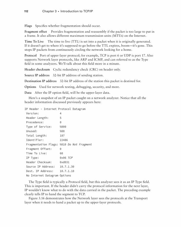
Flags Specifies whether fragmentation should occur.
Fragment offset Provides fragmentation and reassembly if the packet is too large to put in a frame. It also allows different maximum transmission units (MTUs) on the Internet.
Time To Live The time to live (TTL) is set into a packet when it is originally generated. If it doesn’t get to where it’s supposed to go before the TTL expires, boom—it’s gone. This stops IP packets from continuously circling the network looking for a home.
Protocol Port of upper-layer protocol; for example, TCP is port 6 or UDP is port 17. Also supports Network layer protocols, like ARP and ICMP, and can referred to as the Type field in some analyzers. We’ll talk about this field more in a minute.
Header checksum Cyclic redundancy check (CRC) on header only.
Source IP address 32-bit IP address of sending station.
Destination IP address 32-bit IP address of the station this packet is destined for.
Options Used for network testing, debugging, security, and more.
Data After the IP option field, will be the upper-layer data.
Here’s a snapshot of an IP packet caught on a network analyzer. Notice that all the header information discussed previously appears here:
IP Header - Internet Protocol Datagram Version: 4 Header Length: 5 Precedence: 0 Type of Service: %000 Unused: %00 Total Length: 187 Identifier: 22486 Fragmentation Flags: %010 Do Not Fragment Fragment Offset: 0 Time To Live: 60 IP Type: 0x06 TCP Header Checksum: 0xd031 Source IP Address: 10.7.1.30 Dest. IP Address: 10.7.1.10 No Internet Datagram Options
The Type field is typically a Protocol field, but this analyzer sees it as an IP Type field. This is important. If the header didn’t carry the protocol information for the next layer, IP wouldn’t know what to do with the data carried in the packet. The preceding example clearly tells IP to hand the segment to TCP.
Figure 3.16 demonstrates how the Network layer sees the protocols at the Transport layer when it needs to hand a packet up to the upper-layer protocols.

TCP/IP and the DoD Model 113
F I Gu R E 3 .16 The Protocol field in an IP header
TCP UDP
IP
Transportlayer
Port numbersNetwork
layer
6 17
In this example, the Protocol field tells IP to send the data to either TCP port 6 or UDP port 17. But it will be UDP or TCP only if the data is part of a data stream headed for an upper-layer service or application. It could just as easily be destined for Internet Control Message Protocol (ICMP), Address Resolution Protocol (ARP), or some other type of Network layer protocol.
Table 3.3 is a list of some other popular protocols that can be specified in the Protocol field.
TA B LE 3 . 3 Possible protocols found in the Protocol field of an IP header
Protocol Protocol Number
ICMP 1
IP in IP (tunneling) 4
TCP 6
UDP 17
EIGRP 88
OSPF 89
IPv6 41
GRE 47
Layer 2 tunnel (L2TP) 115
You can find a complete list of Protocol field numbers at www.iana.org/assignments/protocol-numbers.

114 Chapter 3 u Introduction to TCP/IP
Internet Control Message Protocol (ICMP)Internet Control Message Protocol (ICMP) works at the Network layer and is used by IP for many different services. ICMP is basically a management protocol and messaging service provider for IP. Its messages are carried as IP datagrams. RFC 1256 is an annex to ICMP, which gives hosts extended capability in discovering routes to gateways.
ICMP packets have the following characteristics:
uu They can provide hosts with information about network problems.
uu They are encapsulated within IP datagrams.
The following are some common events and messages that ICMP relates to:
Destination unreachable If a router can’t send an IP datagram any further, it uses ICMP to send a message back to the sender, advising it of the situation. For example, take a look at Figure 3.17, which shows that interface E0 of the Lab_B router is down.
F I Gu R E 3 .17 ICMP error message is sent to the sending host from the remote router.
Lab_A
Host A
ICMP packet
e0
Lab_B
Host B
e0
When Host A sends a packet destined for Host B, the Lab_B router will send an ICMP des-tination unreachable message back to the sending device, which is Host A in this example.
Buffer full/source quench If a router’s memory buffer for receiving incoming datagrams is full, it will use ICMP to send out this message alert until the congestion abates.
Hops/time exceeded Each IP datagram is allotted a certain number of routers, called hops, to pass through. If it reaches its limit of hops before arriving at its destination, the last router to receive that datagram deletes it. The executioner router then uses ICMP to send an obituary message, informing the sending machine of the demise of its datagram.
Ping Packet Internet Groper (Ping) uses ICMP echo request and reply messages to check the physical and logical connectivity of machines on an internetwork.
Traceroute Using ICMP time-outs, Traceroute is used to discover the path a packet takes as it traverses an internetwork.
TCP/IP and the DoD Model 115
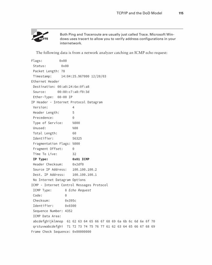
Both Ping and Traceroute are usually just called Trace. Microsoft Win-dows uses tracert to allow you to verify address configurations in your internetwork.
The following data is from a network analyzer catching an ICMP echo request:
Flags: 0x00 Status: 0x00 Packet Length: 78 Timestamp: 14:04:25.967000 12/20/03Ethernet Header Destination: 00:a0:24:6e:0f:a8 Source: 00:80:c7:a8:f0:3d Ether-Type: 08-00 IPIP Header - Internet Protocol Datagram Version: 4 Header Length: 5 Precedence: 0 Type of Service: %000 Unused: %00 Total Length: 60 Identifier: 56325 Fragmentation Flags: %000 Fragment Offset: 0 Time To Live: 32 IP Type: 0x01 ICMP Header Checksum: 0x2df0 Source IP Address: 100.100.100.2 Dest. IP Address: 100.100.100.1 No Internet Datagram OptionsICMP - Internet Control Messages Protocol ICMP Type: 8 Echo Request Code: 0 Checksum: 0x395c Identifier: 0x0300 Sequence Number: 4352 ICMP Data Area: abcdefghijklmnop 61 62 63 64 65 66 67 68 69 6a 6b 6c 6d 6e 6f 70 qrstuvwabcdefghi 71 72 73 74 75 76 77 61 62 63 64 65 66 67 68 69Frame Check Sequence: 0x00000000

116 Chapter 3 u Introduction to TCP/IP
Notice anything unusual? Did you catch the fact that even though ICMP works at the Internet (Network) layer, it still uses IP to do the Ping request? The Type field in the IP header is 0x01, which specifies that the data we’re carrying is owned by the ICMP protocol. Remember, just as all roads lead to Rome, all segments or data must go through IP!
The Ping program uses the alphabet in the data portion of the packet as a payload, typically around 100 bytes by default, unless, of course, you are pinging from a Windows device, which thinks the alphabet stops at the let-ter W (and doesn’t include X, Y, or Z) and then starts at A again. Go figure!
If you remember reading about the Data Link layer and the different frame types in Chapter 2, “Ethernet Technologies and Data Encapsulation,” you should be able to look at the preceding trace and tell what type of Ethernet frame this is. The only fields are destina-tion hardware address, source hardware address, and Ether-Type. The only frame that uses an Ether-Type field exclusively is an Ethernet_II frame.
We’ll move on soon, but before we get into the ARP protocol, let’s take another look at ICMP in action. Figure 3.18 shows an internetwork—it has a router, so it’s an internet-work, right?
F I Gu R E 3 .18 ICMP in action
Server 110.1.2.2/24 10.1.4.2/24
I’m trying totelnet to
10.1.1.5—can you
forward thisrequest?
10.1.5.2/24
10.1.5.3/24
10.1.5.4/24
10.1.5.5/24
10.1.1.0 network?No, never heard of it!
Discard! Create ICMP packet!
Server1 (10.1.2.2) telnets to 10.1.1.5 from a DOS prompt. What do you think Server1 will receive as a response? Server1 will send the Telnet data to the default gateway, which is the router, and the router will drop the packet because there isn’t a network 10.1.1.0 in the routing table. Because of this, Server1 will receive an ICMP destination unreachable back from the router.

TCP/IP and the DoD Model 117
Address Resolution Protocol (ARP)Address Resolution Protocol (ARP) finds the hardware address of a host from a known IP address. Here’s how it works: When IP has a datagram to send, it must inform a Network Access protocol, such as Ethernet or wireless, of the destination’s hardware address on the local network. Remember that it has already been informed by upper-layer protocols of the destination’s IP address. If IP doesn’t find the destination host’s hardware address in the ARP cache, it uses ARP to find this information.
As IP’s detective, ARP interrogates the local network by sending out a broadcast ask-ing the machine with the specified IP address to reply with its hardware address. So basi-cally, ARP translates the software (IP) address into a hardware address—for example, the destination machine’s Ethernet adapter address—and from it, deduces its whereabouts on the LAN by broadcasting for this address. Figure 3.19 shows how an ARP broadcast looks to a local network.
F I Gu R E 3 .19 Local ARP broadcast
I need the Ethernetaddress of 10.1.1.2.
10.1.1.1
IP: 10.1.1.2 = ???
IP: 10.1.1.2Ethernet: 45:AC:24:E3:60:A5
10.1.1.2
I heard that broadcast.The message is for me.
Here is my Ethernet address.
ARP resolves IP addresses to Ethernet (MAC) addresses.
The following trace shows an ARP broadcast—notice that the destination hardware address is unknown and is all Fs in hex (all 1s in binary)—and is a hardware address broadcast:
Flags: 0x00 Status: 0x00 Packet Length: 64 Timestamp: 09:17:29.574000 12/06/03

118 Chapter 3 u Introduction to TCP/IP
Ethernet Header Destination: FF:FF:FF:FF:FF:FF Ethernet Broadcast Source: 00:A0:24:48:60:A5 Protocol Type: 0x0806 IP ARPARP - Address Resolution Protocol Hardware: 1 Ethernet (10Mb) Protocol: 0x0800 IP Hardware Address Length: 6 Protocol Address Length: 4 Operation: 1 ARP Request Sender Hardware Address: 00:A0:24:48:60:A5 Sender Internet Address: 172.16.10.3 Target Hardware Address: 00:00:00:00:00:00 (ignored) Target Internet Address: 172.16.10.10Extra bytes (Padding): ................ 0A 0A 0A 0A 0A 0A 0A 0A 0A 0A 0A 0A 0A 0A 0A 0A 0A 0AFrame Check Sequence: 0x00000000
IP AddressingOne of the most important topics in any discussion of TCP/IP is IP addressing. An IP address is a numeric identifier assigned to each machine on an IP network. It designates the specific location of a device on the network.
An IP address is a software address, not a hardware address—the latter is hard-coded on a network interface card (NIC) and used for finding hosts on a local network. IP addressing was designed to allow hosts on one network to communicate with a host on a different net-work regardless of the type of LANs the hosts are participating in.
Before we get into the more complicated aspects of IP addressing, you need to understand some of the basics. First I’m going to explain some of the fundamentals of IP addressing and its terminology. Then you’ll learn about the hierarchical IP addressing scheme and private IP addresses.
IP TerminologyThroughout this chapter you’re being introduced to several important terms that are vital to understanding the Internet Protocol. Here are a few to get you started:
Bit A bit is one digit, either a 1 or a 0.
Byte A byte is 7 or 8 bits, depending on whether parity is used. For the rest of this chapter, always assume a byte is 8 bits.
Visit ccna .gg/ch3/a for a companion MicroNugget from CBT Nuggets.

IP Addressing 119
Octet An octet, made up of 8 bits, is just an ordinary 8-bit binary number. In this chapter, the terms byte and octet are completely interchangeable.
Network address This is the designation used in routing to send packets to a remote network—for example, 10.0.0.0, 172.16.0.0, and 192.168.10.0.
Broadcast address The address used by applications and hosts to send information to all nodes on a network is called the broadcast address. Examples of layer 3 broadcasts include 255.255.255.255, which is any network, all nodes; 172.16.255.255, which is all subnets and hosts on network 172.16.0.0; and 10.255.255.255, which broadcasts to all subnets and hosts on network 10.0.0.0.
The Hierarchical IP Addressing SchemeAn IP address consists of 32 bits of information. These bits are divided into four sections, referred to as octets or bytes, with each containing 1 byte (8 bits). You can depict an IP address using one of three methods:
uu Dotted-decimal, as in 172.16.30.56
uu Binary, as in 10101100.00010000.00011110.00111000
uu Hexadecimal, as in AC.10.1E.38
All these examples represent the same IP address. Pertaining to IP addressing, hexadeci-mal isn’t used as often as dotted-decimal or binary, but you still might find an IP address stored in hexadecimal in some programs.
The 32-bit IP address is a structured or hierarchical address, as opposed to a flat or nonhierarchical address. Although either type of addressing scheme could have been used, hierarchical addressing was chosen for a good reason. The advantage of this scheme is that it can handle a large number of addresses, namely 4.3 billion (a 32-bit address space with two possible values for each position—either 0 or 1—gives you 232, or 4,294,967,296). The disadvantage of the flat addressing scheme, and the reason it’s not used for IP address-ing, relates to routing. If every address were unique, all routers on the Internet would need to store the address of each and every machine on the Internet. This would make efficient routing impossible, even if only a fraction of the possible addresses were used!
The solution to this problem is to use a two- or three-level hierarchical addressing scheme that is structured by network and host or by network, subnet, and host.
This two- or three-level scheme can also be compared to a telephone number. The first section, the area code, designates a very large area. The second section, the prefix, narrows the scope to a local calling area. The final segment, the customer number, zooms in on the specific connection. IP addresses use the same type of layered structure. Rather than all 32 bits being treated as a unique identifier, as in flat addressing, a part of the address is des-ignated as the network address and the other part is designated as either the subnet and host or just the node address.
Next, we’ll cover IP network addressing and the different classes of address we can use to address our networks.

120 Chapter 3 u Introduction to TCP/IP
Network AddressingThe network address (which can also be called the network number) uniquely identifies each network. Every machine on the same network shares that network address as part of its IP address. For example, in the IP address 172.16.30.56, 172.16 is the network address.
The node address is assigned to, and uniquely identifies, each machine on a network. This part of the address must be unique because it identifies a particular machine—an individual—as opposed to a network, which is a group. This number can also be referred to as a host address. In the sample IP address 172.16.30.56, the 30.56 specifies the node address.
The designers of the Internet decided to create classes of networks based on network size. For the small number of networks possessing a very large number of nodes, they created the rank Class A network. At the other extreme is the Class C network, which is reserved for the numerous networks with a small number of nodes. The class distinction for networks between very large and very small is predictably called the Class B network.
Subdividing an IP address into a network and node address is determined by the class designation of one’s network. Figure 3.20 summarizes the three classes of networks used to address hosts—a subject I’ll explain in much greater detail throughout this chapter.
F I Gu R E 3 . 20 Summary of the three classes of networks
Network
8 bits
Network
Network
Host
8 bits
Network
Network
Host
8 bits
Host
Network
Host
8 bits
Host
Host
Multicast
Research
Class A:
Class B:
Class C:
Class D:
Class E:
To ensure efficient routing, Internet designers defined a mandate for the leading-bits section of the address for each different network class. For example, since a router knows that a Class A network address always starts with a 0, the router might be able to speed a packet on its way after reading only the first bit of its address. This is where the address schemes define the difference between a Class A, a Class B, and a Class C address. Coming up, I’ll discuss the differences between these three classes, followed by a discussion of the Class D and Class E addresses. Classes A, B, and C are the only ranges that are used to address hosts in our networks.
Network Address Range: Class A
The designers of the IP address scheme decided that the first bit of the first byte in a Class A network address must always be off, or 0. This means a Class A address must be between 0 and 127 in the first byte, inclusive.

IP Addressing 121
Consider the following network address:
0xxxxxxx
If we turn the other 7 bits all off and then turn them all on, we’ll find the Class A range of network addresses:
00000000 = 001111111 = 127
So, a Class A network is defined in the first octet between 0 and 127, and it can’t be less or more. Understand that 0 and 127 are not valid in a Class A network because they’re reserved addresses, which I’ll explain soon.
Network Address Range: Class B
In a Class B network, the RFCs state that the first bit of the first byte must always be turned on but the second bit must always be turned off. If you turn the other 6 bits all off and then all on, you will find the range for a Class B network:
10000000 = 12810111111 = 191
As you can see, a Class B network is defined when the first byte is configured from 128 to 191.
Network Address Range: Class C
For Class C networks, the RFCs define the first 2 bits of the first octet as always turned on, but the third bit can never be on. Following the same process as the previous classes, convert from binary to decimal to find the range. Here’s the range for a Class C network:
11000000 = 19211011111 = 223
So, if you see an IP address that starts at 192 and goes to 223, you’ll know it is a Class C IP address.
Network Address Ranges: Classes D and E
The addresses between 224 to 255 are reserved for Class D and E networks. Class D (224–239) is used for multicast addresses and Class E (240–255) for scientific purposes, but I’m not going into these types of addresses because they are beyond the scope of knowledge you need to gain from this book.
Network Addresses: Special Purpose
Some IP addresses are reserved for special purposes, so network administrators can’t ever assign these addresses to nodes. Table 3.4 lists the members of this exclusive little club and the reasons why they’re included in it.

122 Chapter 3 u Introduction to TCP/IP
TA B LE 3 . 4 Reserved IP addresses
Address Function
Network address of all 0s Interpreted to mean “this network or segment.”
Network address of all 1s Interpreted to mean “all networks.”
Network 127.0.0.1 Reserved for loopback tests. Designates the local node and allows that node to send a test packet to itself without generating network traffic.
Node address of all 0s Interpreted to mean “network address” or any host on a specified network.
Node address of all 1s Interpreted to mean “all nodes” on the specified network; for example, 128.2.255.255 means “all nodes” on network 128.2 (Class B address).
Entire IP address set to all 0s Used by Cisco routers to designate the default route. Could also mean “any network.”
Entire IP address set to all 1s (same as 255.255.255.255)
Broadcast to all nodes on the current network; sometimes called an “all 1s broadcast” or local broadcast.
Class A AddressesIn a Class A network address, the first byte is assigned to the network address and the three remaining bytes are used for the node addresses. The Class A format is as follows:
network.node.node.node
For example, in the IP address 49.22.102.70, the 49 is the network address and 22.102.70 is the node address. Every machine on this particular network would have the distinctive net-work address of 49.
Class A network addresses are 1 byte long, with the first bit of that byte reserved and the 7 remaining bits available for manipulation (addressing). As a result, the maximum number of Class A networks that can be created is 128. Why? Because each of the 7 bit positions can be either a 0 or a 1, thus 27, or 128.
To complicate matters further, the network address of all 0s (0000 0000) is reserved to designate the default route (see Table 3.4 in the previous section). Additionally, the address 127, which is reserved for diagnostics, can’t be used either, which means that you can really only use the numbers 1 to 126 to designate Class A network addresses. This means the actual number of usable Class A network addresses is 128 minus 2, or 126.

IP Addressing 123
The IP address 127.0.0.1 is used to test the IP stack on an individual node and cannot be used as a valid host address. However, the loopback address creates a shortcut method for TCP/IP applications and services that run on the same device to communicate with each other.
Each Class A address has 3 bytes (24-bit positions) for the node address of a machine. This means there are 224—or 16,777,216—unique combinations and, therefore, precisely that many possible unique node addresses for each Class A network. Because node addresses with the two patterns of all 0s and all 1s are reserved, the actual maximum usable number of nodes for a Class A network is 224 minus 2, which equals 16,777,214. Either way, that’s a huge number of hosts on a single network segment!
Class A Valid Host IDs
Here’s an example of how to figure out the valid host IDs in a Class A network address:
uu All host bits off is the network address: 10.0.0.0.
uu All host bits on is the broadcast address: 10.255.255.255.
The valid hosts are the numbers in between the network address and the broadcast address: 10.0.0.1 through 10.255.255.254. Notice that 0s and 255s can be valid host IDs. All you need to remember when trying to find valid host addresses is that the host bits can’t all be turned off or on at the same time.
Class B AddressesIn a Class B network address, the first 2 bytes are assigned to the network address and the remaining 2 bytes are used for node addresses. The format is as follows:
network.network.node.node
For example, in the IP address 172.16.30.56, the network address is 172.16 and the node address is 30.56.
With a network address being 2 bytes (8 bits each), you get 216 unique combinations. But the Internet designers decided that all Class B network addresses should start with the binary digit 1, then 0. This leaves 14 bit positions to manipulate, therefore 16,384, or 214 unique Class B network addresses.
A Class B address uses 2 bytes for node addresses. This is 216 minus the two reserved patterns of all 0s and all 1s for a total of 65,534 possible node addresses for each Class B network.
Class B Valid Host IDs
Here’s an example of how to find the valid hosts in a Class B network:
uu All host bits turned off is the network address: 172.16.0.0.
uu All host bits turned on is the broadcast address: 172.16.255.255.
124 Chapter 3 u Introduction to TCP/IP
The valid hosts would be the numbers in between the network address and the broadcast address: 172.16.0.1 through 172.16.255.254.
Class C AddressesThe first 3 bytes of a Class C network address are dedicated to the network portion of the address, with only 1 measly byte remaining for the node address. Here’s the format:
network.network.network.node
Using the example IP address 192.168.100.102, the network address is 192.168.100 and the node address is 102.
In a Class C network address, the first three bit positions are always the binary 110. The calculation is as follows: 3 bytes, or 24 bits, minus 3 reserved positions leaves 21 positions. Hence, there are 221, or 2,097,152, possible Class C networks.
Each unique Class C network has 1 byte to use for node addresses. This leads to 28, or 256, minus the two reserved patterns of all 0s and all 1s, for a total of 254 node addresses for each Class C network.
Class C Valid Host IDs
Here’s an example of how to find a valid host ID in a Class C network:
uu All host bits turned off is the network ID: 192.168.100.0.
uu All host bits turned on is the broadcast address: 192.168.100.255.
The valid hosts would be the numbers in between the network address and the broadcast address: 192.168.100.1 through 192.168.100.254.
Private IP Addresses (RFC 1918)The people who created the IP addressing scheme also created private IP addresses. These addresses can be used on a private network, but they’re not routable through the Internet. This is designed for the purpose of creating a measure of well-needed security, but it also conveniently saves valuable IP address space.
If every host on every network was required to have real routable IP addresses, we would have run out of IP addresses to hand out years ago. But by using private IP addresses, ISPs, corporations, and home users only need a relatively tiny group of bona fide IP addresses to connect their networks to the Internet. This is economical because they can use private IP addresses on their inside networks and get along just fine.
To accomplish this task, the ISP and the corporation—the end user, no matter who they are—need to use something called Network Address Translation (NAT), which basi-cally takes a private IP address and converts it for use on the Internet. (NAT is covered in Chapter 13, “Network Address Translation.”) Many people can use the same real IP

IP Addressing 125
address to transmit out onto the Internet. Doing things this way saves megatons of address space—good for us all!
The reserved private addresses are listed in Table 3.5.
TA B LE 3 .5 Reserved IP address space
Address Class Reserved Address Space
Class A 10.0.0.0 through 10.255.255.255
Class B 172.16.0.0 through 172.31.255.255
Class C 192.168.0.0 through 192.168.255.255
You must know your private address space to become Cisco certified!
So, What Private IP Address Should I use?
That’s a really great question: Should you use Class A, Class B, or even Class C private addressing when setting up your network? Let’s take Acme Corporation in SF as an example. This company is moving into a new building and needs a whole new network. It has 14 departments, with about 70 users in each. You could probably squeeze one or two Class C addresses to use, or maybe you could use a Class B, or even a Class A just for fun.
The rule of thumb in the consulting world is, when you’re setting up a corporate network—regardless of how small it is—you should use a Class A network address because it gives you the most flexibility and growth options. For example, if you used the 10.0.0.0 network address with a /24 mask, then you’d have 65,536 networks, each with 254 hosts. Lots of room for growth with that network!
But if you’re setting up a home network, you’d opt for a Class C address because it is the easiest for people to understand and configure. Using the default Class C mask gives you one network with 254 hosts—plenty for a home network.
With the Acme Corporation, a nice 10.1.x.0 with a /24 mask (the x is the subnet for each department) makes this easy to design, install, and troubleshoot.

126 Chapter 3 u Introduction to TCP/IP
IPv4 Address TypesMost people use the term broadcast as a generic term, and most of the time, we understand what they mean—but not always! For example, you might say, “The host broadcasted through a router to a DHCP server,” but, well, it’s pretty unlikely that this would ever really happen. What you probably mean—using the correct technical jargon—is, “The DHCP client broad-casted for an IP address and a router then forwarded this as a unicast packet to the DHCP server.” Oh, and remember that with IPv4, broadcasts are pretty important, but with IPv6, there aren’t any broadcasts sent at all—now there’s something to look forward to reading about in Chapter 14!
Okay, I’ve referred to IP addresses throughout the preceding chapters and now all throughout this chapter, and even showed you some examples. But I really haven’t gone into the different terms and uses associated with them yet, and it’s about time I did. So here are the address types that I’d like to define for you:
Loopback (localhost) Used to test the IP stack on the local computer. Can be any address from 127.0.0.1 through 127.255.255.254.
Layer 2 broadcasts These are sent to all nodes on a LAN.
Broadcasts (layer 3) These are sent to all nodes on the network.
Unicast This is an address for a single interface, and these are used to send packets to a single destination host.
Multicast These are packets sent from a single source and transmitted to many devices on different networks. Referred to as “one-to-many.”
Layer 2 BroadcastsFirst, understand that layer 2 broadcasts are also known as hardware broadcasts—they only go out on a LAN, but they don’t go past the LAN boundary (router).
The typical hardware address is 6 bytes (48 bits) and looks something like 45:AC:24:E3:60:A5. The broadcast would be all 1s in binary, which would be all Fs in hexadecimal, as in ff:ff:ff:ff:ff:ff and shown in Figure 3.21.
Every network interface card (NIC) will receive and read the frame, including the router, since this was a layer 2 broadcast, but the router would never, ever forward this!
Layer 3 BroadcastsThen there are the plain old broadcast addresses at layer 3. Broadcast messages are meant to reach all hosts on a broadcast domain. These are the network broadcasts that have all host bits on.
Here’s an example that you’re already familiar with: The network address of 172.16.0.0 255.255.0.0 would have a broadcast address of 172.16.255.255—all host bits on. Broadcasts

IPv4 Address Types 127
can also be “any network and all hosts,” as indicated by 255.255.255.255, and shown in Figure 3.22.
F I Gu R E 3 . 21 Local layer 2 broadcasts
I need to send thisto everyone on my
local network!
Ethernet: FF:FF:FF:FF:FF:FF
I heard that localLAN broadcast.
I need to read this!
F I Gu R E 3 . 22 Layer 3 broadcasts
I need to send this toeveryone on my local network,
as well as to everynetwork I can get to!
Ethernet: FF:FF:FF:FF:FF:FF
I heard that all-networks broadcast.I need to read this!
IP: 255.255.255.255
In Figure 3.22, all hosts on the LAN will get this broadcast on their NIC, including the router, but by default the router would never forward this packet.
Unicast AddressA unicast is defined as a single IP address that’s assigned to a network interface card and is the destination IP address in a packet—in other words, it’s used for directing packets to a specific host.

128 Chapter 3 u Introduction to TCP/IP
In Figure 3.23 both the MAC address and the destination IP address are for a single NIC on the network. All hosts on the broadcast domain would receive this frame and accept it. Only the destination NIC of 10.1.1.2 would accept the packet; the other NICs would discard the packet.
F I Gu R E 3 . 23 Unicast address
I need to send a packet toa host on a remote network!
This needs to go tomy router!
Ethernet: 00.00.0c.12.34.56
I see the frame, butthis is not my MAC!
Discard!
IP: 10.1.1.2
I see that frame. It’sfor me! Now I needto read the packet!
Multicast AddressMulticast is a different beast entirely. At first glance, it appears to be a hybrid of unicast and broadcast communication, but that isn’t quite the case. Multicast does allow point-to-multipoint communication, which is similar to broadcasts, but it happens in a different manner. The crux of multicast is that it enables multiple recipients to receive messages without flooding the messages to all hosts on a broadcast domain. However, this is not the default behavior—it’s what we can do with multicasting if it’s configured correctly!
Multicast works by sending messages or data to IP multicast group addresses. Unlike with broadcasts, which aren’t forwarded, routers then forward copies of the packet out to every interface that has hosts subscribed to that group address. This is where multicast differs from broadcast messages—with multicast communication, copies of packets, in theory, are sent only to subscribed hosts. For example, when I say in theory, I mean that the hosts will receive a multicast packet destined for 224.0.0.10. This is an EIGRP packet, and only a router run-ning the EIGRP protocol will read these. All hosts on the broadcast LAN, and Ethernet is a broadcast multi-access LAN technology, will pick up the frame, read the destination address, then immediately discard the frame unless they’re in the multicast group. This saves PC processing, not LAN bandwidth. Be warned though—multicasting can cause some serious LAN congestion if it’s not implemented carefully! Figure 3.24 shows a Cisco router sending an EIGRP multicast packet on the local LAN and only the other Cisco router will accept and read this packet.

Summary 129
F I Gu R E 3 . 24 EIGRP multicast example
We see thatmulticast frame, but
this is not for us!
I run EIGRP! This isfor me!
I have EIGRP data!
224.0.0.10
There are several different groups that users or applications can subscribe to. The range of multicast addresses starts with 224.0.0.0 and goes through 239.255.255.255. As you can see, this range of addresses falls within IP Class D address space based on classful IP assignment.
SummaryIf you made it this far and understood everything the first time through, you should be extremely proud of yourself! We really covered a lot of ground in this chapter, but under-stand that the information in it is critical to being able to navigate well through the rest of this book.
If you didn’t get a complete understanding the first time around, don’t stress. It really wouldn’t hurt you to read this chapter more than once. There is still a lot of ground to cover, so make sure you’ve got this material all nailed down. That way, you’ll be ready for more, and just so you know, there’s a lot more! What we’re doing up to this point is building a solid foundation to build upon as you advance.
With that in mind, after you learned about the DoD model, the layers, and associ-ated protocols, you learned about the oh-so-important topic of IP addressing. I discussed in detail the difference between each address class, how to find a network address and broadcast address, and what denotes a valid host address range. I can’t stress enough how important it is for you to have this critical information unshakably understood before moving on to Chapter 4!
Since you’ve already come this far, there’s no reason to stop now and waste all those brainwaves and new neural connections. So don’t stop—go through the written lab and review questions at the end of this chapter and make sure you understand each answer’s explanation. The best is yet to come!
Visit ccna .gg/ch3/b for a companion MicroNugget from CBT Nuggets.

130 Chapter 3 u Introduction to TCP/IP
Exam Essentials
Differentiate the DoD and the OSI network models. The DoD model is a condensed ver-sion of the OSI model, composed of four layers instead of seven, but is nonetheless like the OSI model in that it can be used to describe packet creation and devices and protocols can be mapped to its layers.
Identify Process/Application layer protocols. Telnet is a terminal emulation program that allows you to log into a remote host and run programs. File Transfer Protocol (FTP) is a con-nection-oriented service that allows you to transfer files. Trivial FTP (TFTP) is a connection-less file transfer program. Simple Mail Transfer Protocol (SMTP) is a sendmail program.
Identify Host-to-Host layer protocols. Transmission Control Protocol (TCP) is a connection-oriented protocol that provides reliable network service by using acknowledgments and flow control. User Datagram Protocol (UDP) is a connectionless protocol that provides low over-head and is considered unreliable.
Identify Internet layer protocols. Internet Protocol (IP) is a connectionless protocol that provides network address and routing through an internetwork. Address Resolution Protocol (ARP) finds a hardware address from a known IP address. Reverse ARP (RARP) finds an IP address from a known hardware address. Internet Control Message Protocol (ICMP) provides diagnostics and destination unreachable messages.
Describe the functions of DNS and DHCP in the network. Dynamic Host Configuration Protocol (DHCP) provides network configuration information (including IP addresses) to hosts, eliminating the need to perform the configurations manually. Domain Name Service (DNS) resolves hostnames—both Internet names such as www.lammle.com and device names such as Workstation 2—to IP addresses, eliminating the need to know the IP address of a device for connection purposes.
Identify what is contained in the TCP header of a connection-oriented transmission. The fields in the TCP header include the source port, destination port, sequence number, acknowl-edgment number, header length, a field reserved for future use, code bits, window size, check-sum, urgent pointer, options field, and finally, the data field.
Identify what is contained in the UDP header of a connectionless transmission. The fields in the UDP header include only the source port, destination port, length, checksum, and data. The smaller number of fields as compared to the TCP header comes at the expense of providing none of the more advanced functions of the TCP frame.
Identify what is contained in the IP header. The fields of an IP header include version, header length, priority or type of service, total length, identification, flags, fragment offset, time to live, protocol, header checksum, source IP address, destination IP address, options, and finally, data.
Compare and contrast UDP and TCP characteristics and features. TCP is connection-oriented, acknowledged, and sequenced and has flow and error control, while UDP is con-nectionless, unacknowledged, and not sequenced and provides no error or flow control.

Exam Essentials 131
Understand the role of port numbers. Port numbers are used to identify the protocol or service that is to be used in the transmission.
Identify the role of ICMP. Internet Control Message Protocol (ICMP) works at the Network layer and is used by IP for many different services. ICMP is a management protocol and mes-saging service provider for IP.
Define the Class A IP address range. The IP range for a Class A network is 1–126. This provides 8 bits of network addressing and 24 bits of host addressing by default.
Define the Class B IP address range. The IP range for a Class B network is 128–191. Class B addressing provides 16 bits of network addressing and 16 bits of host addressing by default.
Define the Class C IP address range. The IP range for a Class C network is 192 through 223. Class C addressing provides 24 bits of network addressing and 8 bits of host addressing by default.
Identify the private IP ranges. The Class A private address range is 10.0.0.0 through 10.255.255.255. The Class B private address range is 172.16.0.0 through 172.31.255.255. The Class C private address range is 192.168.0.0 through 192.168.255.255.
Understand the difference between a broadcast, unicast, and multicast address. A broad-cast is to all devices in a subnet, a unicast is to one device, and a multicast is to some but not all devices.

132 Chapter 3 u Introduction to TCP/IP
Written LabsIn this section, you’ll complete the following labs to make sure you’ve got the information and concepts contained within them fully dialed in:
Lab 3.1: TCP/IP
Lab 3.2: Mapping Applications to the DoD Model
The answers to these labs can be found in Appendix A, “Answers to Written Labs.”
Written Lab 3.1: TCP/IPAnswer the following questions about TCP/IP:
1. What is the Class C address range in decimal and in binary?
2. What layer of the DoD model is equivalent to the Transport layer of the OSI model?
3. What is the valid range of a Class A network address?
4. What is the 127.0.0.1 address used for?
5. How do you find the network address from a listed IP address?
6. How do you find the broadcast address from a listed IP address?
7. What is the Class A private IP address space?
8. What is the Class B private IP address space?
9. What is the Class C private IP address space?
10. What are all the available characters that you can use in hexadecimal addressing?
Written Lab 3.2: Mapping Applications to the DoD ModelThe four layers of the DoD model are Process/Application, Host-to-Host, Internet, and Network Access. Identify the layer of the DoD model on which each of these protocols operates.
1. Internet Protocol (IP)
2. Telnet
3. FTP
4. SNMP
5. DNS
6. Address Resolution Protocol (ARP)
7. DHCP/BootP
8. Transmission Control Protocol (TCP)

Written Labs 133
9. X Window
10. User Datagram Protocol (UDP)
11. NFS
12. Internet Control Message Protocol (ICMP)
13. Reverse Address Resolution Protocol (RARP)
14. Proxy ARP
15. TFTP
16. SMTP
17. LPD

134 Chapter 3 u Introduction to TCP/IP
Review Questions
The following questions are designed to test your understanding of this chapter’s material. For more information on how to get additional ques-tions, please see this book’s introduction.
The answers to these questions can be found in Appendix B, “Answers to Chapter Review Questions.”
1. What must happen if a DHCP IP conflict occurs?
A. Proxy ARP will fix the issue.
B. The client uses a gratuitous ARP to fix the issue.
C. The administrator must fix the conflict by hand at the DHCP server.
D. The DHCP server will reassign new IP addresses to both computers.
2. Which of the following Application layer protocols sets up a secure session that’s simi-lar to Telnet?
A. FTP
B. SSH
C. DNS
D. DHCP
3. Which of the following mechanisms is used by the client to avoid a duplicate IP address during the DHCP process?
A. ping
B. traceroute
C. gratuitous arp
D. pathping
4. What protocol is used to find the hardware address of a local device?
A. RARP
B. ARP
C. IP
D. ICMP
E. BootP

Review Questions 135
5. Which of the following are layers in the TCP/IP model? (Choose three.)
A. Application
B. Session
C. Transport
D. Internet
E. Data Link
F. Physical
6. Which class of IP address provides a maximum of only 254 host addresses per network ID?
A. Class A
B. Class B
C. Class C
D. Class D
E. Class E
7. Which of the following describe the DHCP Discover message? (Choose two.)
A. It uses FF:FF:FF:FF:FF:FF as a layer 2 broadcast.
B. It uses UDP as the Transport layer protocol.
C. It uses TCP as the Transport layer protocol.
D. It does not use a layer 2 destination address.
8. Which layer 4 protocol is used for a Telnet connection?
A. IP
B. TCP
C. TCP/IP
D. UDP
E. ICMP
9. Private IP addressing was specified in RFC __________.
10. Which of the following services use TCP? (Choose three.)
A. DHCP
B. SMTP
C. SNMP
D. FTP
E. HTTP
F. TFTP
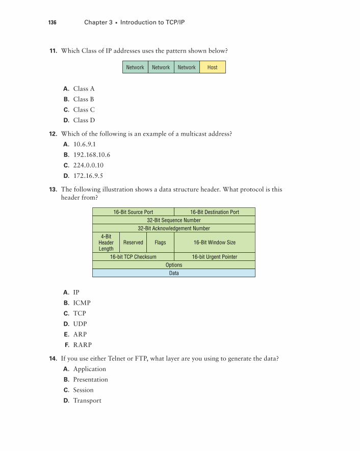
136 Chapter 3 u Introduction to TCP/IP
11. Which Class of IP addresses uses the pattern shown below?
Network Network Network Host
A. Class A
B. Class B
C. Class C
D. Class D
12. Which of the following is an example of a multicast address?
A. 10.6.9.1
B. 192.168.10.6
C. 224.0.0.10
D. 172.16.9.5
13. The following illustration shows a data structure header. What protocol is this header from?
4-BitHeaderLength
Reserved Flags 16-Bit Window Size
Host-to-HostHost-to-Host
16-Bit Destination Port16-Bit Source Port
16-bit Urgent Pointer16-bit TCP Checksum
32-Bit Sequence Number32-Bit Acknowledgement Number
OptionsData
A. IP
B. ICMP
C. TCP
D. UDP
E. ARP
F. RARP
14. If you use either Telnet or FTP, what layer are you using to generate the data?
A. Application
B. Presentation
C. Session
D. Transport

Review Questions 137
15. The DoD model (also called the TCP/IP stack) has four layers. Which layer of the DoD model is equivalent to the Network layer of the OSI model?
A. Application
B. Host-to-Host
C. Internet
D. Network Access
16. Which two of the following are private IP addresses?
A. 12.0.0.1
B. 168.172.19.39
C. 172.20.14.36
D. 172.33.194.30
E. 192.168.24.43
17. What layer in the TCP/IP stack is equivalent to the Transport layer of the OSI model?
A. Application
B. Host-to-Host
C. Internet
D. Network Access
18. Which statements are true regarding ICMP packets? (Choose two).
A. ICMP guarantees datagram delivery.
B. ICMP can provide hosts with information about network problems.
C. ICMP is encapsulated within IP datagrams.
D. ICMP is encapsulated within UDP datagrams.
19. What is the address range of a Class B network address in binary?
A. 01xxxxxx
B. 0xxxxxxx
C. 10xxxxxx
D. 110xxxxx

138 Chapter 3 u Introduction to TCP/IP
20. Drag the steps in the DHCP process and place them in the correct order on the right.
left list:
DHCPOffer
DHCPDiscover
DHCPAck
DHCPRequest
right list:
Drop Target A
Drop Target B
Drop Target C
Drop Target D