chapter 22faculty.chemeketa.edu/csekafet/elt133/ch22.pdf · • it consists of a stator with stator...
TRANSCRIPT

Chapter 22Polyphase Systems in Power Applications

Objectives
• Describe a basic polyphase machine• Discuss the advantages of polyphase generators
and motors in power applications• Analyze three-phase generator and transformer
configurations• Analyze three-phase generators with three-phase
loads• Discuss power measurements in three-phase
systems

Basic Polyphase Machines• Polyphase generators simultaneously produce
multiple sinusoidal voltages that are separated by certain constant phase angles.
• Polyphase generation is accomplished by multiple windings rotating through a magnetic field.
• A simple two-phase generator consists of two conductive loops of wire, separated by 90, rotating in a magnetic field.
• Polyphase motors operate with multiple-phase sinusoidal inputs.

Basic 3-Phase GeneratorA polyphase generator with 3 separate conductor windings placed at 120 intervals generates 3 sinusoidal voltages separated from each other by phase angles of 120.
• Note: at any instant of time, the algebriac sum of the three phase voltages is zero.
• Van = Vapsin ωt
• Vbn = Vbpsin(ωt - 120 )
• Vcn = Vcpsin(ωt - 240°) = Vcpsin(ωt + 120°)
Where n is the neutral or common point of all three windings

Practical Three-Phase Generator• A practical three-phase generator uses a rotating
electromagnet.• The electromagnet is created by passing dc through a
winding around the rotor (field winding).• The stationary outer portion of the generator is called the
stator.• Three separate windings are placed 120 apart around the
stator.

Practical Three-Phase Generator
Three-phase voltages are induced in the three stator windings as the magnetic field rotates (rotor).
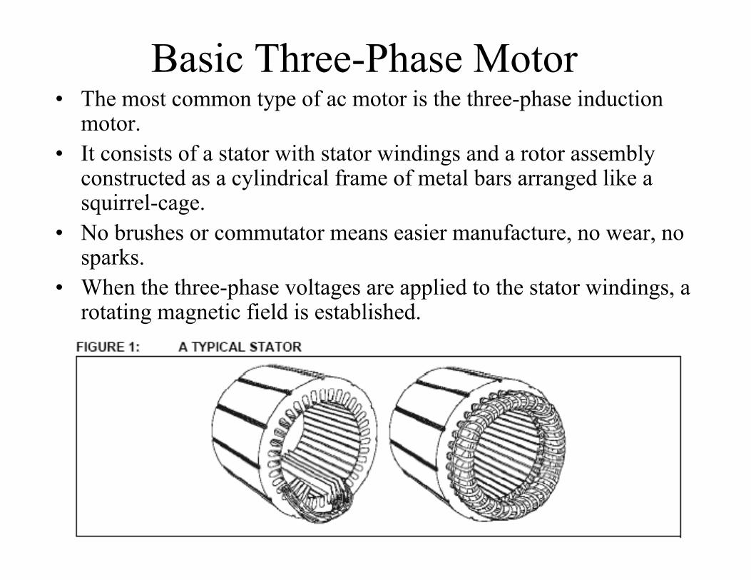
Basic Three-Phase Motor• The most common type of ac motor is the three-phase induction
motor.• It consists of a stator with stator windings and a rotor assembly
constructed as a cylindrical frame of metal bars arranged like a squirrel-cage.
• No brushes or commutator means easier manufacture, no wear, no sparks.
• When the three-phase voltages are applied to the stator windings, a rotating magnetic field is established.

Basic Three-Phase Motor (cont.)
• As the magnetic field rotates, currents are induced in the conductors of the squirrel-cage rotor.
• The interaction of the induced currents and the magnetic field produces forces that cause the rotor to turn.

Advantages of Polyphase Generators• The size of the copper wire required to carry current from
the generator to a load can be reduced when a polyphase rather than a single-phase system is used.
• Consider a single-phase 120V sinusoidal voltage induced in a winding and the applied load of 60.– The generator must deliver 20 A.– Two conductors are required to supply the load, so the total copper
cross section must handle 4 A.

Advantages of Polyphase Generators• Now consider a two-phase 120V sinusoidal voltages induced in both
windings (spaced 90º apart) and the applied load of 120 to each winding (equivalent to a single-phase winding applied to two 120Ω resistors connected in parallel for an equivalent load power of 240W.– The generator must still deliver 2A but each winding supplies only 1A to
its respective load.– Three conductors are required to supply the load (the neutral wire is the
return wire), so the total copper cross section must handle 3.414 A.– This system uses smaller copper gauge wire when compared to a single-
phase system when delivering the same amount of load power.

Advantages of Polyphase Generators• Now consider a three-phase 120V sinusoidal voltages induced in all three
windings (spaced 120º apart) and the applied load of 180 to each winding (equivalent to a single-phase winding applied to three 180Ω resistors connected in parallel for an equivalent load power of 240W).– The generator must still deliver 2A but each winding supplies only 667mA to
its respective load.– Four conductors are required to supply the load (the neutral wire is the
return wire), so the total copper cross section must handle 2 A.– This system uses smaller copper gauge wire when compared to a single-phase
and two-phase systems when delivering the same amount of load power.– When the current through the neutral wire is 0A, the generator is connected
to a “balanced load”. The neutral wire is needed to return current for unbalanced loads.

Advantages of Three-Phase Generators: Recap
• Notice that four conductors, including the neutral, are required to carry the currents to and from the loads.
• The current in each conductor is 667 mA.• The current in the neutral is the phasor sum of the
three load currents and is equal to zero.• A balanced load is the condition where all load
currents are equal and the neutral current is zero.• The total copper cross section must handle 2 A.

Polyphase Example 1• A certain three-phase unbalanced load in a four-wire system has
currents of IL1 20º A, IL2ے2 = .100º A-ے140º A, and IL3 = 1.5ے3 =Determine the current in the neutral line.

Advantage of Constant Power• In a three-phase system, the sum of the instantaneous voltages is always the
same; therefore, the power has a constant value.– The following diagram illustrates this concept for a two-phase system but
the concept is identical for a three-phase system.
• A constant load power means a uniform conversion of mechanical to electrical energy, which is an important consideration. Suitable for applications where a high torque is required at low speed and a low torque at high speed; such asmachine tools and traction.
• Power(VA-single-phase) = V*I ; Power(VA-three-phase) = √3 V*I

Advantage of a Constant, Rotating Magnetic Field
• In a polyphase motor, the motor’s rotor is pulled around at a constant rotational velocity by the rotating magnetic field, producing a constant shaft rotation.
• Advantages over single-phase AC motors is higher operating efficiencies, self-starting, and the ability to rotate in any direction at startup.

Advantage of a Constant, Rotating Magnetic Field
• A single-phase system produces a magnetic field that fluctuates in flux density and reverses direction during each cycle without providing the advantage of constant rotation, hence it is unsuitable for many applications.
• Single-phase AC induction motors require a self-starting capacitor and/or centrifugal switch.
• Single-phase AC induction motors do not provide smooth shaft rotation as compared to polyphase systems which makes them less efficient to operate and limits the torque they can generate to drive mechanical loads.

Advantage of a Constant, Rotating Magnetic Field

Advantage of a Constant, Rotating Magnetic Field
• In a polyphase motor, the motor’s rotor is pulled around at a constant rotational velocity because there is always current flowing through more than one winding. This produces a rotating magnetic field, producing a constant shaft rotation.
• The more phases present, the smoother the rotating magnetic field and shaft rotation. Three-phase systems provide very smooth shaft rotation.
• Polyphase AC induction motors do no not require a self-starting capacitor and/or centrifugal switch and can be wired to rotate in a chosen direction at startup.

Three-Phase Transformer Connections:
• There are only 4 possible transformer combinations:– Delta to Delta - use: industrial applications – Delta to Wye - use : most common; commercial
and industrial – Wye to Delta - use : high voltage transmissions – Wye to Wye - use : rare, don't use; causes
harmonics and balancing problems.

Three-Phase Transformer Connections:

Three-Phase Transformer Connections:

Three-Phase Transformer Connections:

• The following photograph shows a bank of step-up transformers at the Grand Coulee hydroelectric dam in Washington state. Several transformers (green in color) may be seen from this vantage point, and they are grouped in threes: three transformers per hydroelectric generator, wired together in some form of three-phase configuration. The photograph doesn't reveal the primary winding connections, but it appears the secondaries are connected in a Y configuration, being that there is only one large high-voltage insulator protruding from each transformer. This suggests the other side of each transformer's secondary winding is at or near ground potential, which could only be true in a Y system. The building to the left is the powerhouse, where the generators and turbines are housed. On the right, the sloping concrete wall is the downstream face of the dam:

The Y-Connected Generator
• When the loads are perfectly balanced, the neutral current is zero, so only 3-wires are required.
• Where the loads are not equal, a neutral is essential to provide a return current path, because the neutral current has a nonzero value.
• Voltages across the generator windings are called phase voltages (V).
• Current through the windings are called phase currents (I).
The Y-Connected Generator
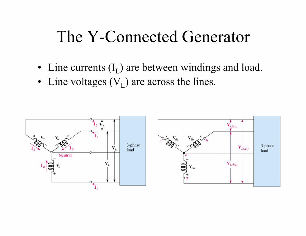
• Line currents (IL) are between windings and load.• Line voltages (VL) are across the lines.
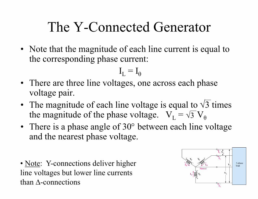
The Y-Connected Generator• Note that the magnitude of each line current is equal to
the corresponding phase current:IL = I
• There are three line voltages, one across each phase voltage pair.
• The magnitude of each line voltage is equal to 3 times the magnitude of the phase voltage. VL = Vθ
• There is a phase angle of 30 between each line voltage and the nearest phase voltage.
• Note: Y-connections deliver higher line voltages but lower line currents than ∆-connections
3

The Y-Connected Generator (cont.)Figure 22--17 Phase voltage diagram.
Figure 22--18 Phase diagram for the phase voltages and line voltages in a Y-connected, three-phase system.

Polyphase Example 2• Determine the line voltages.

The -Connected GeneratorThe windings of a three-phase generator can be arranged to form a -connected generator.

The -Connected Generator
• This is a 3-wire system, so only a single voltage magnitude is available:
VL = V
• The magnitude of each line current is equal to 3 times the magnitude of the phase current. IL = 3 Iθ
• There is a phase angle of 30 between each line current and the nearest phase current.
• Note: ∆-connections deliver higher line currents but lower line voltages than Y-connections

The -Connected Generator (cont.)Figure 22--22 Phase current diagram for the -connected system.
Figure 22--23 Phasor diagram of phase currents and line currents.
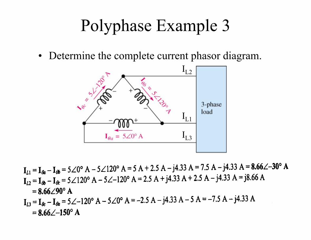
Polyphase Example 3• Determine the complete current phasor diagram.
IL2
IL1
IL3

Polyphase Example 3 (cont.)IL2
IL1IL3

Polyphase Example 4• For a balanced 3-phase system the power (S) may be determined according
to the formula S = √3 VL IL VA (volt-amperes). A 3-phase, WYE-connected, 100-kVA alternator (AC generator) has a voltage of 600V between the lines. If this alternator is reconnected in DELTA, determine the rated line voltage and rated line current (drawn by balanced 60-Ω loads) for this DELTA configuration.
– For WYE, VL = √3 Vθ, IL = Iθ– For DELTA, VL = Vθ, IL = √3 Iθ– To convert WYE to DELTA, we need to find Vθ:
• Vθ = VL/√3 = 600V/1.732 = 346.4V• For DELTA, Vθ = VL = 346.4V (we don’t need to consider the angles for each Vθ)

Polyphase Example 4 (cont.)– The rated line current for WYE:
• IL = 100kVA / (√3 VL) = 100kVA / ((1.732)(600V) = 100kVA / 1039.2V = 96.2A
– The rated line current for DELTA:• IL = 100kVA / (√3 VL) = 100kVA / ((1.732)(346.4V) = 100kVA / 600V = 166.7A
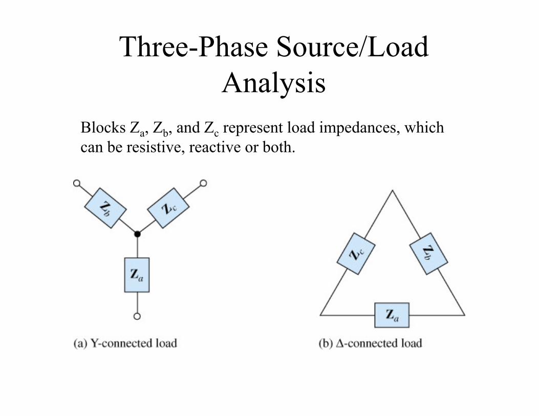
Three-Phase Source/Load Analysis
Blocks Za, Zb, and Zc represent load impedances, which can be resistive, reactive or both.

The Y-Y System• An important feature of a Y-connected source is that two different
values of 3-phase voltage are available: the phase voltage and the line voltage.– The Y-connected load is used for phase voltage.– The -connected load is used for line voltage.
• For a balanced load, all the phase currents are equal, and the neutral current is zero.
• For an unbalanced load, each phase current is different, and the neutral current is nonzero.

The Y- System• Each phase of the load has the full line voltage across it.• Line currents equal the corresponding phase currents, and
each line current divides into two load currents.• For a balanced load, the current in each load is:
IL = 3 IZ
IL(x) = 3 IZ(x) where x is a, b, or c

The -Y System• The line voltages are equal to the corresponding phase voltages of the
source.• Each load current equals the corresponding line current (IL = IZ).• The relationship between the load voltages and the corresponding
phase voltages is:V = 3 VZ
V(x) = 3 VZ(x) where x is a, b, or c

The - System• Load voltage, line voltage, and source phase voltage are all
equal for a given phase.• When the load is balanced, all voltages are equal.• For a balanced load and equal source phase voltages:
IL = 3 IZ

Polyphase Example 5• Determine the line voltages and load currents.

Three-Phase Power Measurement• Power is measured in three-phase systems using
two or three wattmeters.• The wattmeter uses a basic electrodynamometer-
type movement consisting of two coils.• One coil is used to measure the current, and the
other is used to measure the voltage.• The needle is the meter is deflected proportionally
to the current through a load and the voltage across the load, thus indicating power in a load.

Three-Phase Power Measurement (cont.)

Three-Wattmeter MethodPower can be measured in a a balanced or unbalanced 3-phase load of either Y or type.

Two-Wattmeter MethodThe voltage coil of each wattmeter is connected across a line voltage and the current has a line current through it. Ptot = P1 P2

Polyphase Example 5• Determine the load power.

Summary
• A simple two-phase generator consists of two conductive loops of wire, separated by 90, rotating in a magnetic field.
• A simple three-phase generator consists of three conductive loops separated by 120.
• Three advantages of polyphase systems over single-phase systems are a smaller copper cross section for the same power delivered to the load, and a constant, rotating magnetic field.

Summary
• In a Y-connected generator, IL = I and VL = 3V
• In a Y-connected generator, there is a 30difference between each line voltage and the nearest phase voltage.
• In a -connected generator, VL = V and IL = 3I• In a -connected generator there is a 30
difference between each line current and the nearest phase current.

Summary
• A balanced load is one in which all the impedances are equal.
• Power is measured in a three-phase load using either the three-wattmeter method or the two-wattmeter method.