chapter modern ethernet - houston independent … · chapter 6: modern ethernet 5 ... has four...
TRANSCRIPT

CHAPTER 6Modern EthernetThe Network+ Certification exam expects you to know how to
• 1.2 Specify the main features of 802.2 (Logical Link Control) [and] 802.3(Ethernet): speed, access method, topology, media
• 1.3 Specify the characteristics (for example: speed, length, topology, andcable type) of the following cable standards: 10BaseT and 10BaseFL; 100BaseTXand 100BaseFX; 1000BaseTX, 1000BaseCX, 1000BaseSX, and 1000BaseLX;10GBaseSR, 10GBaseLR, and 10GBaseER
• 1.4 Recognize the following media connectors and describe their uses: RJ-11,RJ-45, F-type, ST, SC, IEEE 1394, LC, MTRJ
• 1.6 Identify the purposes, features, and functions of the following networkcomponents: hubs, switches
• 2.3 Identify the OSI layers at which the following network componentsoperate: hubs, switches
To achieve these goals, you must be able to• Define the characteristics, cabling, and connectors used in 10BaseT and
10BaseFL• Explain how to connect multiple Ethernet segments• Define the characteristics, cabling, and connectors used with 100Base and
Gigabit Ethernet
Historical/ConceptualThe first generation of Ethernet network technologies enjoyed substantial adoption inthe networking world, but their bus topology continued to be their Achilles’ heel—a sin-gle break anywhere on the bus completely shut down an entire network. In the mid-1980s, IBM unveiled a competing network technology called Token Ring. You’ll get thecomplete discussion of Token Ring in the next chapter, but it’s enough for now to saythat Token Ring used a physical star topology. With a star topology, any single break inthe network affected only the one system using that cable to connect to the network—herest of the network continued to operate normally. As a result, Token Ring began to takesubstantial market share away from Ethernet through the second half of the 1980s.
In response to this threat, Ethernet manufacturers scrambled to make a new form ofEthernet that would have three major new features. First, this new Ethernet would use aphysical star to match the robustness of Token Ring. Second, this new Ethernet would
1
All-In-One / Network+ Certification All-in-One Exam Guide / Meyers / 225345-2 / Chapter 6
P:\010Comp\All-in-1\345-2\ch06.vpFriday, September 17, 2004 3:25:59 PM
Color profile: Generic CMYK printer profileComposite Default screen
dump the use of more expensive coax and adopt inexpensive UTP cabling. Third, thisnew Ethernet would still use the same frame types and speeds of the older Ethernets, al-lowing for easy interconnections of this new Ethernet with older Ethernet networks. In1990, working in close concert with the IEEE, the Ethernet manufacturers unveiled anew Ethernet standard: the now famous 10BaseT. From the moment of its introduction,10BaseT’s ease of installation, reliability, and low price reestablished Ethernet as the net-working technology of choice, reducing Token Ring from market dominance to minorplayer today.
In the years since 1990, a series of faster Ethernet versions have come onto thenetworking scene, gradually pushing 10BaseT into the background. Even though itstime in the spotlight has now passed, 10BaseT defined nearly every aspect of the Ethernetwe use today, from cabling to topology. A solid understanding of 10BaseT is therefore animportant part of your network tech foundation, as it will help you understand all thecurrent Ethernet technologies. Let’s take an in-depth look at 10BaseT, from its topologyto its technology, and see why 10BaseT and the newer Ethernet technologies based on itnow dominate the networking world.
Test Specific
10BaseTThe most important thing to remember about 10BaseT is that it is still Ethernet. Except forthe type of cabling and the topology, 10BaseT is identical to 10Base2 or 10Base5. 10BaseTuses the same frames as the earlier Ethernets. 10BaseT operates at the same speed of 10Mbps. Machines still identify other machines by their MAC addresses and use CSMA/CD.The key difference between 10BaseT and its physical bus topology predecessors is the loca-tion of the Ethernet segment. Let’s take a closer look at each of these issues.
10BaseT Topology10Base2 and 10Base5 each use a physical bus topology. With a physical bus, you have a ca-ble winding around the network and every computer connects to this single cable. Somemight take exception to this—10Base5 may truly use a single cable, but isn’t 10Base2 actu-ally a number of cables connected together via the T-connectors at each PC? Yes, that’strue—but in the case of 10Base2, all those cables connected together form a single bus.The existence of those T-connectors all along the 10Base2 bus doesn’t detract from the factthat the bus carries the same signals in the same way as the truly single 10Base5 cable. Asfar as the network is concerned, both 10Base5 and 10Base2 use a single cable.
In the previous chapter, one of the words used to define that single cable was a “seg-ment.” Let’s take the definition of a segment one step further. A segment is a single physi-cal connection, terminated on both ends, to which computers may connect to form anetwork. In 10Base5 and 10Base2, the segment winds its way around the network, withterminators sitting at either end.
Network+ Certification All-in-One Exam Guide
2
All-In-One / Network+ Certification All-in-One Exam Guide / Meyers / 225345-2 / Chapter 6
P:\010Comp\All-in-1\345-2\ch06.vpFriday, September 17, 2004 3:25:59 PM
Color profile: Generic CMYK printer profileComposite Default screen
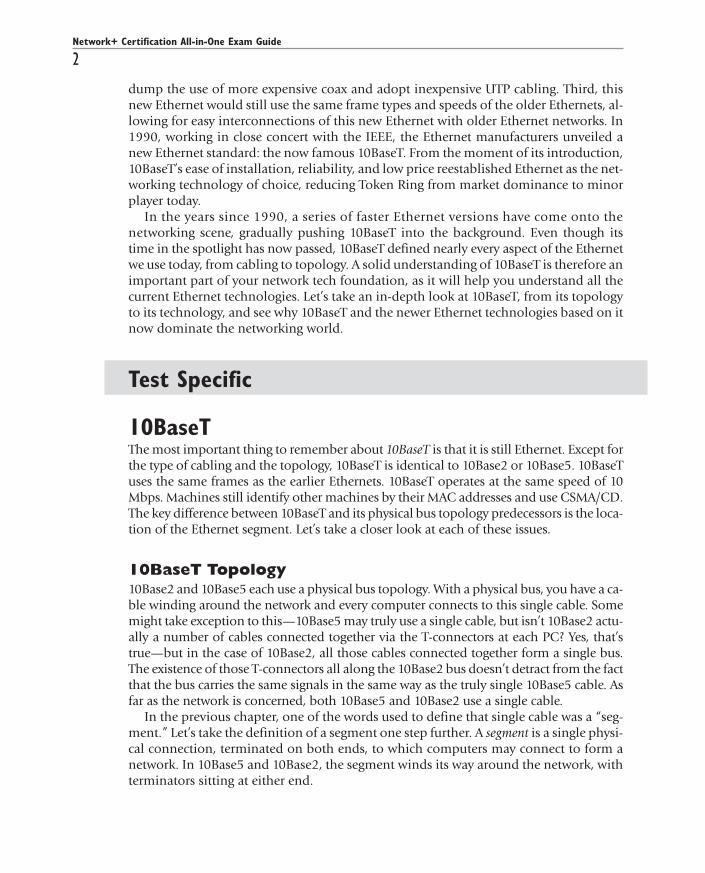
10BaseT also has a segment, but a 10BaseT segment doesn’t wind all over the network.10BaseT uses a physical star topology in which each node connects to a central hub (seeFigure 6-1). The segment is still there—it’s just shrunk into the hub (Figure 6-2).
TIP Depending on who’s talking, you may hear 10BaseT called a star topology,a bus topology, or a star bus topology. Which term a particular tech uses todescribe 10BaseT’s topology often depends on her job description. For someonewhose primary job is installing cable, 10BaseT is a star. Similarly, a software
engineer writing a device driver for an Ethernet NIC could not care less where the cablesgo; she thinks of 10BaseT as a bus. The right answer is star bus!
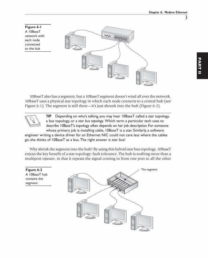
Why shrink the segment into the hub? By using this hybrid star bus topology, 10BaseTenjoys the key benefit of a star topology: fault tolerance. The hub is nothing more than amultiport repeater, in that it repeats the signal coming in from one port to all the other
Chapter 6: Modern Ethernet
3
All-In-One / Network+ Certification All-in-One Exam Guide / Meyers / 225345-2 / Chapter 6
PA
RT
II
Figure 6-1A 10BaseTnetwork witheach nodeconnectedto the hub
Figure 6-2A 10BaseT hubcontains thesegment.
P:\010Comp\All-in-1\345-2\ch06.vpFriday, September 17, 2004 3:26:00 PM
Color profile: Generic CMYK printer profileComposite Default screen
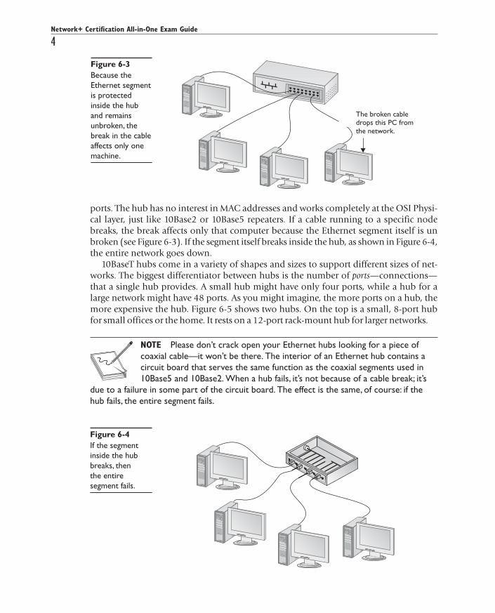
ports. The hub has no interest in MAC addresses and works completely at the OSI Physi-cal layer, just like 10Base2 or 10Base5 repeaters. If a cable running to a specific nodebreaks, the break affects only that computer because the Ethernet segment itself is unbroken (see Figure 6-3). If the segment itself breaks inside the hub, as shown in Figure 6-4,the entire network goes down.
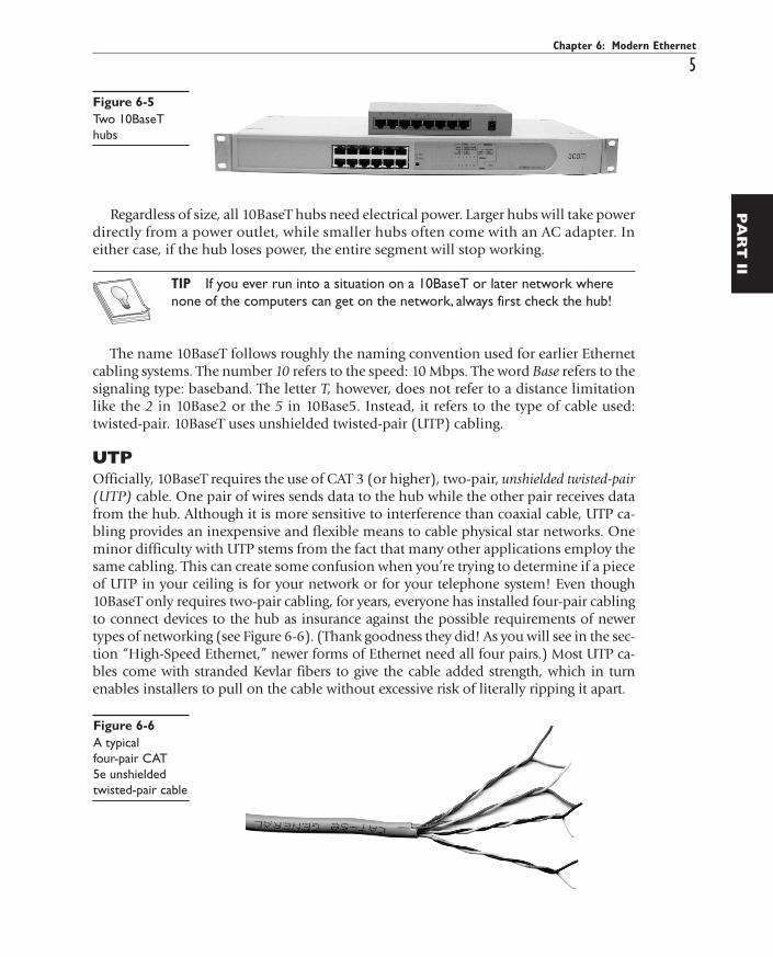
10BaseT hubs come in a variety of shapes and sizes to support different sizes of net-works. The biggest differentiator between hubs is the number of ports—connections—that a single hub provides. A small hub might have only four ports, while a hub for alarge network might have 48 ports. As you might imagine, the more ports on a hub, themore expensive the hub. Figure 6-5 shows two hubs. On the top is a small, 8-port hubfor small offices or the home. It rests on a 12-port rack-mount hub for larger networks.
NOTE Please don’t crack open your Ethernet hubs looking for a piece ofcoaxial cable—it won’t be there. The interior of an Ethernet hub contains acircuit board that serves the same function as the coaxial segments used in10Base5 and 10Base2. When a hub fails, it’s not because of a cable break; it’s
due to a failure in some part of the circuit board. The effect is the same, of course: if thehub fails, the entire segment fails.
All-In-One / Network+ Certification All-in-One Exam Guide / Meyers / 225345-2 / Chapter 6All-In-One / Network+ Certification All-in-One Exam Guide / Meyers / 225345-2 / Chapter 6
Network+ Certification All-in-One Exam Guide
4
All-In-One / Network+ Certification All-in-One Exam Guide / Meyers / 225345-2 / Chapter 6
Figure 6-3Because theEthernet segmentis protectedinside the huband remainsunbroken, thebreak in the cableaffects only onemachine.
Figure 6-4If the segmentinside the hubbreaks, thenthe entiresegment fails.
P:\010Comp\All-in-1\345-2\ch06.vpFriday, September 17, 2004 3:26:01 PM
Color profile: Generic CMYK printer profileComposite Default screen
Regardless of size, all 10BaseT hubs need electrical power. Larger hubs will take powerdirectly from a power outlet, while smaller hubs often come with an AC adapter. Ineither case, if the hub loses power, the entire segment will stop working.
TIP If you ever run into a situation on a 10BaseT or later network wherenone of the computers can get on the network, always first check the hub!
The name 10BaseT follows roughly the naming convention used for earlier Ethernetcabling systems. The number 10 refers to the speed: 10 Mbps. The word Base refers to thesignaling type: baseband. The letter T, however, does not refer to a distance limitationlike the 2 in 10Base2 or the 5 in 10Base5. Instead, it refers to the type of cable used:twisted-pair. 10BaseT uses unshielded twisted-pair (UTP) cabling.
UTPOfficially, 10BaseT requires the use of CAT 3 (or higher), two-pair, unshielded twisted-pair(UTP) cable. One pair of wires sends data to the hub while the other pair receives datafrom the hub. Although it is more sensitive to interference than coaxial cable, UTP ca-bling provides an inexpensive and flexible means to cable physical star networks. Oneminor difficulty with UTP stems from the fact that many other applications employ thesame cabling. This can create some confusion when you’re trying to determine if a pieceof UTP in your ceiling is for your network or for your telephone system! Even though10BaseT only requires two-pair cabling, for years, everyone has installed four-pair cablingto connect devices to the hub as insurance against the possible requirements of newertypes of networking (see Figure 6-6). (Thank goodness they did! As you will see in the sec-tion “High-Speed Ethernet,” newer forms of Ethernet need all four pairs.) Most UTP ca-bles come with stranded Kevlar fibers to give the cable added strength, which in turnenables installers to pull on the cable without excessive risk of literally ripping it apart.
Chapter 6: Modern Ethernet
5
All-In-One / Network+ Certification All-in-One Exam Guide / Meyers / 225345-2 / Chapter 6
PA
RT
II
Figure 6-5Two 10BaseThubs
Figure 6-6A typicalfour-pair CAT5e unshieldedtwisted-pair cable
P:\010Comp\All-in-1\345-2\ch06.vpFriday, September 17, 2004 3:26:01 PM
Color profile: Generic CMYK printer profileComposite Default screen
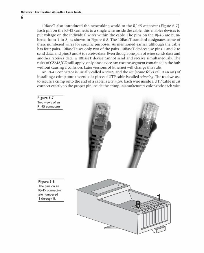
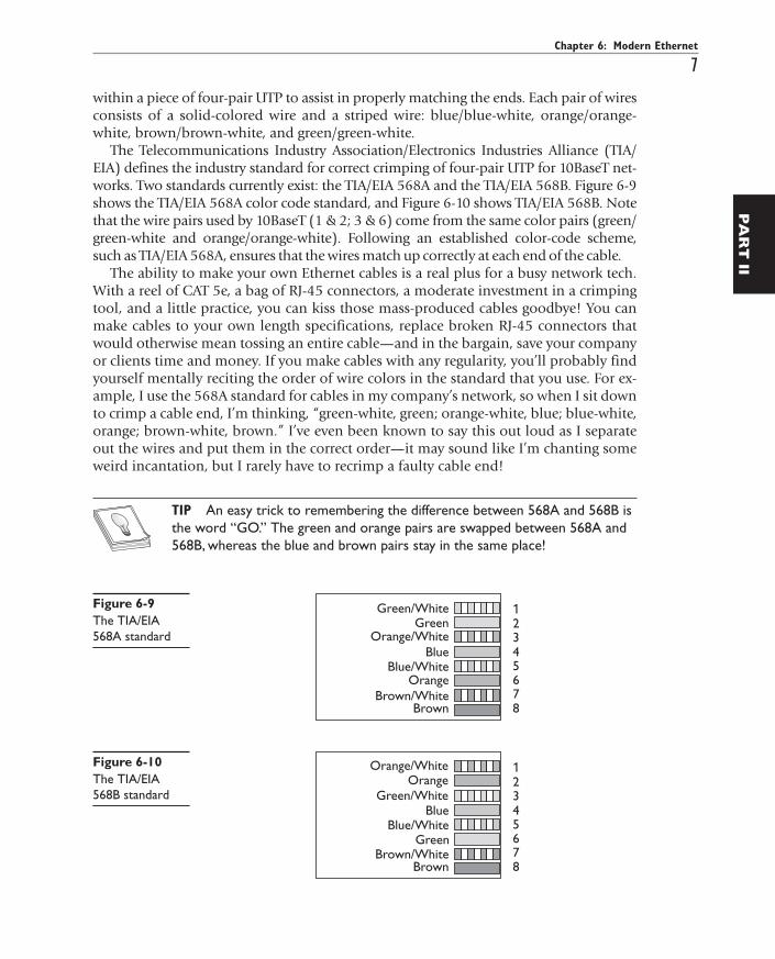
10BaseT also introduced the networking world to the RJ-45 connector (Figure 6-7).Each pin on the RJ-45 connects to a single wire inside the cable; this enables devices toput voltage on the individual wires within the cable. The pins on the RJ-45 are num-bered from 1 to 8, as shown in Figure 6-8. The 10BaseT standard designates some ofthese numbered wires for specific purposes. As mentioned earlier, although the cablehas four pairs, 10BaseT uses only two of the pairs. 10BaseT devices use pins 1 and 2 tosend data, and pins 3 and 6 to receive data. Even though one pair of wires sends data andanother receives data, a 10BaseT device cannot send and receive simultaneously. Therules of CSMA/CD still apply: only one device can use the segment contained in the hubwithout causing a collision. Later versions of Ethernet will change this rule.
An RJ-45 connector is usually called a crimp, and the act (some folks call it an art) ofinstalling a crimp onto the end of a piece of UTP cable is called crimping. The tool we useto secure a crimp onto the end of a cable is a crimper. Each wire inside a UTP cable mustconnect exactly to the proper pin inside the crimp. Manufacturers color-code each wire
Network+ Certification All-in-One Exam Guide
6
All-In-One / Network+ Certification All-in-One Exam Guide / Meyers / 225345-2 / Chapter 6
Figure 6-7Two views of anRJ-45 connector
Figure 6-8The pins on anRJ-45 connectorare numbered1 through 8.
P:\010Comp\All-in-1\345-2\ch06.vpFriday, September 17, 2004 3:26:02 PM
Color profile: Generic CMYK printer profileComposite Default screen
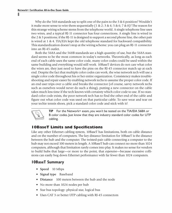
within a piece of four-pair UTP to assist in properly matching the ends. Each pair of wiresconsists of a solid-colored wire and a striped wire: blue/blue-white, orange/orange-white, brown/brown-white, and green/green-white.
The Telecommunications Industry Association/Electronics Industries Alliance (TIA/EIA) defines the industry standard for correct crimping of four-pair UTP for 10BaseT net-works. Two standards currently exist: the TIA/EIA 568A and the TIA/EIA 568B. Figure 6-9shows the TIA/EIA 568A color code standard, and Figure 6-10 shows TIA/EIA 568B. Notethat the wire pairs used by 10BaseT (1 & 2; 3 & 6) come from the same color pairs (green/green-white and orange/orange-white). Following an established color-code scheme,such as TIA/EIA 568A, ensures that the wires match up correctly at each end of the cable.
The ability to make your own Ethernet cables is a real plus for a busy network tech.With a reel of CAT 5e, a bag of RJ-45 connectors, a moderate investment in a crimpingtool, and a little practice, you can kiss those mass-produced cables goodbye! You canmake cables to your own length specifications, replace broken RJ-45 connectors thatwould otherwise mean tossing an entire cable—and in the bargain, save your companyor clients time and money. If you make cables with any regularity, you’ll probably findyourself mentally reciting the order of wire colors in the standard that you use. For ex-ample, I use the 568A standard for cables in my company’s network, so when I sit downto crimp a cable end, I’m thinking, “green-white, green; orange-white, blue; blue-white,orange; brown-white, brown.” I’ve even been known to say this out loud as I separateout the wires and put them in the correct order—it may sound like I’m chanting someweird incantation, but I rarely have to recrimp a faulty cable end!
TIP An easy trick to remembering the difference between 568A and 568B isthe word “GO.” The green and orange pairs are swapped between 568A and568B, whereas the blue and brown pairs stay in the same place!
All-In-One / Network+ Certification All-in-One Exam Guide / Meyers / 225345-2 / Chapter 6
PA
RT
IIChapter 6: Modern Ethernet
7
All-In-One / Network+ Certification All-in-One Exam Guide / Meyers / 225345-2 / Chapter 6
Figure 6-9The TIA/EIA568A standard
Figure 6-10The TIA/EIA568B standard
P:\010Comp\All-in-1\345-2\ch06.vpFriday, September 17, 2004 3:26:02 PM
Color profile: Generic CMYK printer profileComposite Default screen
Network+ Certification All-in-One Exam Guide
8
All-In-One / Network+ Certification All-in-One Exam Guide / Meyers / 225345-2 / Chapter 6
Why do the 568 standards say to split one of the pairs to the 3 & 6 position? Wouldn’tit make more sense to wire them sequentially (1 & 2; 3 & 4; 5 & 6; 7 & 8)? The reason forthis strange wiring scheme stems from the telephone world. A single telephone line usestwo wires, and a typical RJ-11 connector has four connections. A single line is wired inthe 2 & 3 positions; if the RJ-11 is designed to support a second phone line, the other pairis wired at 1 & 4. TIA/EIA kept the old telephone standard for backward compatibility.This standardization doesn’t stop at the wiring scheme: you can plug an RJ-11 connectorinto an RJ-45 outlet.
Both the 568A and the 568B standards see a high quantity of use, but the 568A stan-dard seems to be the most common in today’s networks. Theoretically, as long as eachend of each cable uses the same color code, many color codes could be used within thesame building and everything would still work. 10BaseT devices do not care what colorthe wires are, they just need to have the pins on the RJ-45 connector match up at eachend. Despite the fact that multiple color codes can work, the wise network tech will use asingle color code throughout his or her entire organization. Consistency makes trouble-shooting and repair easier by enabling network techs to assume the proper color code. Ifan end user trips over a cable and breaks the connector (of course, savvy network techssuch as ourselves would never do such a thing), putting a new connector on the cabletakes much less time if the tech knows with certainty which color code to use. If no stan-dard color code exists, the poor network tech has to find the other end of the cable andfigure out what color code was used on that particular cable. To save wear and tear onyour techie tennis shoes, pick a standard color code and stick with it!
TIP For the Network+ exam, you won’t be tested on the TIA/EIA 568A orB color codes. Just know that they are industry standard color codes for UTPcabling.
10BaseT Limits and SpecificationsLike any other Ethernet cabling system, 10BaseT has limitations, both on cable distanceand on the number of computers. The key distance limitation for 10BaseT is the distancebetween the hub and the computer. The twisted-pair cable connecting a computer to thehub may not exceed 100 meters in length. A 10BaseT hub can connect no more than 1024computers, although that limitation rarely comes into play. It makes no sense for vendorsto build hubs that large—or more to the point, that expensive—because excessive colli-sions can easily bog down Ethernet performance with far fewer than 1024 computers.
10BaseT Summary
• Speed 10 Mbps
• Signal type Baseband
• Distance 100 meters between the hub and the node
• No more than 1024 nodes per hub
• Star bus topology: physical star, logical bus
• Uses CAT 3 or better UTP cabling with RJ-45 connectors
P:\010Comp\All-in-1\345-2\ch06.vpFriday, September 17, 2004 3:26:03 PM
Color profile: Generic CMYK printer profileComposite Default screen
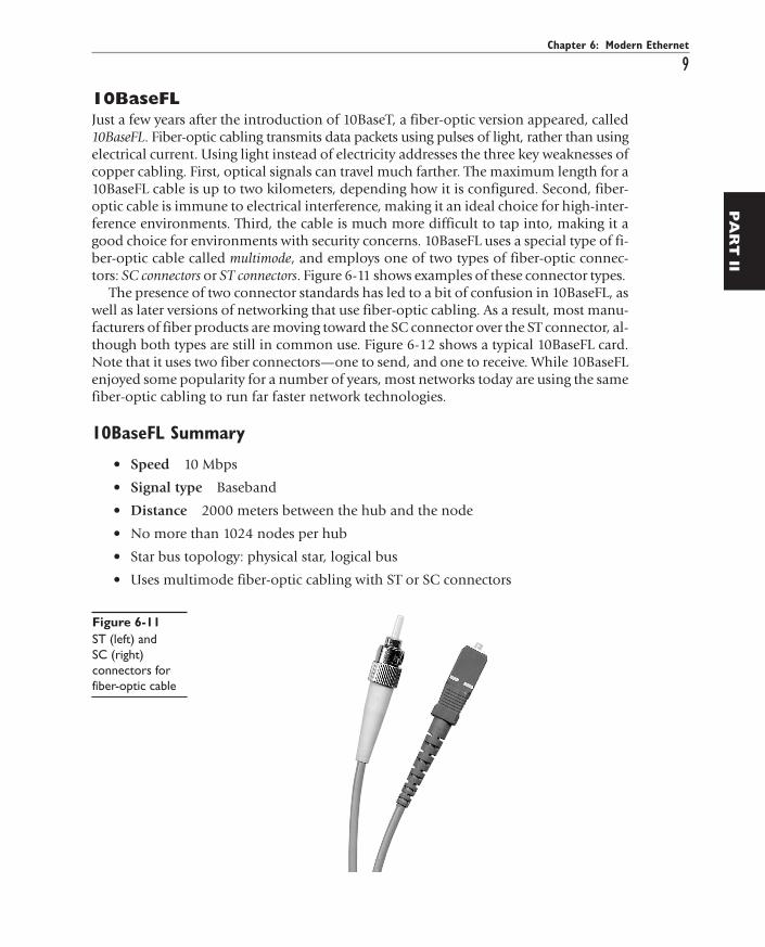
10BaseFLJust a few years after the introduction of 10BaseT, a fiber-optic version appeared, called10BaseFL. Fiber-optic cabling transmits data packets using pulses of light, rather than usingelectrical current. Using light instead of electricity addresses the three key weaknesses ofcopper cabling. First, optical signals can travel much farther. The maximum length for a10BaseFL cable is up to two kilometers, depending how it is configured. Second, fiber-optic cable is immune to electrical interference, making it an ideal choice for high-inter-ference environments. Third, the cable is much more difficult to tap into, making it agood choice for environments with security concerns. 10BaseFL uses a special type of fi-ber-optic cable called multimode, and employs one of two types of fiber-optic connec-tors: SC connectors or ST connectors. Figure 6-11 shows examples of these connector types.
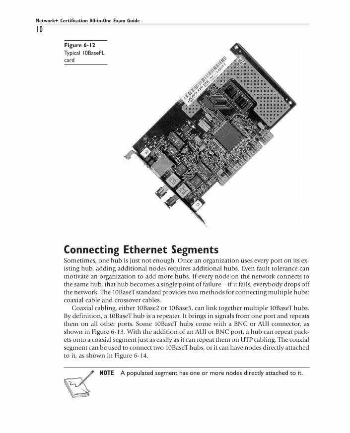
The presence of two connector standards has led to a bit of confusion in 10BaseFL, aswell as later versions of networking that use fiber-optic cabling. As a result, most manu-facturers of fiber products are moving toward the SC connector over the ST connector, al-though both types are still in common use. Figure 6-12 shows a typical 10BaseFL card.Note that it uses two fiber connectors—one to send, and one to receive. While 10BaseFLenjoyed some popularity for a number of years, most networks today are using the samefiber-optic cabling to run far faster network technologies.
10BaseFL Summary
• Speed 10 Mbps
• Signal type Baseband
• Distance 2000 meters between the hub and the node
• No more than 1024 nodes per hub
• Star bus topology: physical star, logical bus
• Uses multimode fiber-optic cabling with ST or SC connectors
Chapter 6: Modern Ethernet
9
All-In-One / Network+ Certification All-in-One Exam Guide / Meyers / 225345-2 / Chapter 6
PA
RT
II
Figure 6-11ST (left) andSC (right)connectors forfiber-optic cable
P:\010Comp\All-in-1\345-2\ch06.vpFriday, September 17, 2004 3:26:03 PM
Color profile: Generic CMYK printer profileComposite Default screen
Network+ Certification All-in-One Exam Guide
10
All-In-One / Network+ Certification All-in-One Exam Guide / Meyers / 225345-2 / Chapter 6
Connecting Ethernet SegmentsSometimes, one hub is just not enough. Once an organization uses every port on its ex-isting hub, adding additional nodes requires additional hubs. Even fault tolerance canmotivate an organization to add more hubs. If every node on the network connects tothe same hub, that hub becomes a single point of failure—if it fails, everybody drops offthe network. The 10BaseT standard provides two methods for connecting multiple hubs:coaxial cable and crossover cables.
Coaxial cabling, either 10Base2 or 10Base5, can link together multiple 10BaseT hubs.By definition, a 10BaseT hub is a repeater. It brings in signals from one port and repeatsthem on all other ports. Some 10BaseT hubs come with a BNC or AUI connector, asshown in Figure 6-13. With the addition of an AUI or BNC port, a hub can repeat pack-ets onto a coaxial segment just as easily as it can repeat them on UTP cabling. The coaxialsegment can be used to connect two 10BaseT hubs, or it can have nodes directly attachedto it, as shown in Figure 6-14.
NOTE A populated segment has one or more nodes directly attached to it.
Figure 6-12Typical 10BaseFLcard
P:\010Comp\All-in-1\345-2\ch06.vpFriday, September 17, 2004 3:26:04 PM
Color profile: Generic CMYK printer profileComposite Default screen

Chapter 6: Modern Ethernet
11
All-In-One / Network+ Certification All-in-One Exam Guide / Meyers / 225345-2 / Chapter 6
PA
RT
II
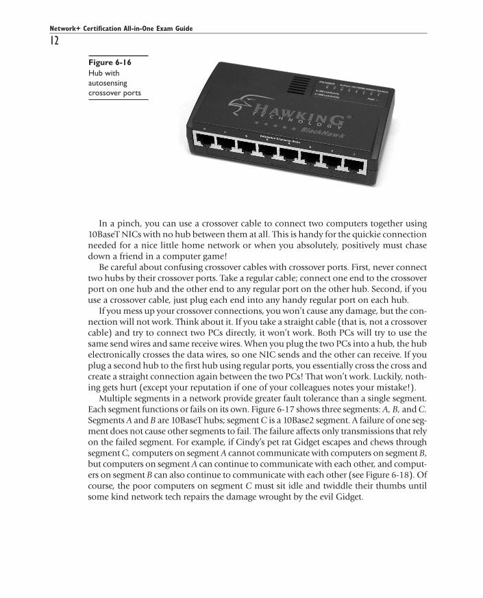
Hubs can also connect to each other via special twisted-pair cables called crossovercables. A standard cable cannot be used to connect two hubs, because both hubs will at-tempt to send data on the second pair of wires (3 & 6) and will listen for data on the firstpair (1 & 2). A crossover cable reverses the sending and receiving pairs on one end of thecable (see Figure 6-15). One end of the cable is wired according to the TIA/EIA 568Astandard, while the other end is wired according to the TIA/EIA 568B standard. With thesending and receiving pairs reversed, the hubs can hear each other; hence the need fortwo standards for connecting RJ-45 jacks to UTP cables. To spare network techs the trou-ble of making special crossover cables, most older hubs have a special crossover portthat crosses the wires inside the hub, as you can see in Figure 6-13, above. Unfortunately,when describing and labeling their crossover ports, hub manufacturers use a wide vari-ety of terms, including crossover, uplink, in port, and out port. Most modern hubs haveautosensing ports that turn themselves into crossover ports if necessary for communica-tion (see Figure 6-16).
Figure 6-1310BaseT hub withBNC connector
Figure 6-14The segmentconnecting twohubs can bepopulated withmachines.
Figure 6-15A crossover cablereverses thesending andreceiving pairs.
P:\010Comp\All-in-1\345-2\ch06.vpFriday, September 17, 2004 3:26:04 PM
Color profile: Generic CMYK printer profileComposite Default screen
Network+ Certification All-in-One Exam Guide
12
All-In-One / Network+ Certification All-in-One Exam Guide / Meyers / 225345-2 / Chapter 6
In a pinch, you can use a crossover cable to connect two computers together using10BaseT NICs with no hub between them at all. This is handy for the quickie connectionneeded for a nice little home network or when you absolutely, positively must chasedown a friend in a computer game!
Be careful about confusing crossover cables with crossover ports. First, never connecttwo hubs by their crossover ports. Take a regular cable; connect one end to the crossoverport on one hub and the other end to any regular port on the other hub. Second, if youuse a crossover cable, just plug each end into any handy regular port on each hub.
If you mess up your crossover connections, you won’t cause any damage, but the con-nection will not work. Think about it. If you take a straight cable (that is, not a crossovercable) and try to connect two PCs directly, it won’t work. Both PCs will try to use thesame send wires and same receive wires. When you plug the two PCs into a hub, the hubelectronically crosses the data wires, so one NIC sends and the other can receive. If youplug a second hub to the first hub using regular ports, you essentially cross the cross andcreate a straight connection again between the two PCs! That won’t work. Luckily, noth-ing gets hurt (except your reputation if one of your colleagues notes your mistake!).
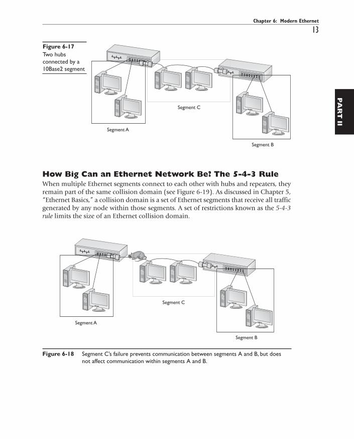
Multiple segments in a network provide greater fault tolerance than a single segment.Each segment functions or fails on its own. Figure 6-17 shows three segments: A, B, and C.Segments A and B are 10BaseT hubs; segment C is a 10Base2 segment. A failure of one seg-ment does not cause other segments to fail. The failure affects only transmissions that relyon the failed segment. For example, if Cindy’s pet rat Gidget escapes and chews throughsegment C, computers on segment A cannot communicate with computers on segment B,but computers on segment A can continue to communicate with each other, and comput-ers on segment B can also continue to communicate with each other (see Figure 6-18). Ofcourse, the poor computers on segment C must sit idle and twiddle their thumbs untilsome kind network tech repairs the damage wrought by the evil Gidget.
Figure 6-16Hub withautosensingcrossover ports
P:\010Comp\All-in-1\345-2\ch06.vpFriday, September 17, 2004 3:26:05 PM
Color profile: Generic CMYK printer profileComposite Default screen
Chapter 6: Modern Ethernet
13
All-In-One / Network+ Certification All-in-One Exam Guide / Meyers / 225345-2 / Chapter 6
PA
RT
II
How Big Can an Ethernet Network Be? The 5-4-3 RuleWhen multiple Ethernet segments connect to each other with hubs and repeaters, theyremain part of the same collision domain (see Figure 6-19). As discussed in Chapter 5,“Ethernet Basics,” a collision domain is a set of Ethernet segments that receive all trafficgenerated by any node within those segments. A set of restrictions known as the 5-4-3rule limits the size of an Ethernet collision domain.
Figure 6-17Two hubsconnected by a10Base2 segment
Figure 6-18 Segment C’s failure prevents communication between segments A and B, but doesnot affect communication within segments A and B.
P:\010Comp\All-in-1\345-2\ch06.vpFriday, September 17, 2004 3:26:05 PM
Color profile: Generic CMYK printer profileComposite Default screen

A Useful ApproximationFor Ethernet networks to function properly, each node must detect when its own trans-missions collide with those of another node. When a node detects a collision, it waits arandom period of time and then re-sends the packet. (Refer back to Chapter 5 for a moredetailed discussion of CSMA/CD.) If the sending node fails to detect a collision, it won’tknow to resend the packet, and the packet will be lost. Ethernet nodes stop checking forcollisions once they send the last byte of each data packet. If the network is large enoughthat the last byte leaves the sending node before the first byte reaches every other nodeon the network, an undetected collision can occur. In the event of a collision betweentwo machines on the extreme edges of the network, neither node retransmits its datapacket, causing the data packets to be lost. Clearly, a collision domain that’s too big canbe a serious problem!
The question, then, is: “How big is too big?” A precise answer would require a seriesof arcane calculations that determine variables with thrilling names like round-trip signalpropagation delay and interpacket gap. Fortunately, the average network tech doesn’t needto do these difficult calculations. The networking industry has developed a generalrule—the so-called 5-4-3 rule—that enables technicians to build networks within safesize limits without needing to earn advanced math degrees.
The 5-4-3 rule is pretty easy to remember: it states that in a collision domain, no twonodes may be separated by more than 5 segments, 4 repeaters, and 3 populated segments.
To calculate a network’s compliance with the 5-4-3 rule, trace the worst-case path be-tween two machines—in other words, the path between two machines that will yield the
Network+ Certification All-in-One Exam Guide
14
All-In-One / Network+ Certification All-in-One Exam Guide / Meyers / 225345-2 / Chapter 6
Figure 6-19 An Ethernet collision domain
P:\010Comp\All-in-1\345-2\ch06.vpFriday, September 17, 2004 3:26:06 PM
Color profile: Generic CMYK printer profileComposite Default screen

highest number of segments, repeaters, and populated segments. We consider a segmentpopulated if any systems are connected to that segment. This might then beg the ques-tion: “Why would anyone want to have a segment that isn’t populated? That’s easy—sometimes we use a separate segment as a way to connect other segments.
Figure 6-20 shows a network with 5 segments, 4 repeaters, and 3 populated segments.The path between machines A and C represents the worst-case path because the packetsmust pass through all of the segments and repeaters on the network. The paths betweenA and B, or B and C, are irrelevant for calculating compliance with the 5-4-3 rule becausea longer path exists between two other machines. The path between machine A and ma-chine C uses all five segments, all four repeaters, and all three populated segments.
NOTE When calculating the 5-4-3 rule, a hub counts as both a repeater and asegment.
The 5-4-3 rule’s limitations apply not to the entire network, but rather to the pathswithin the network. Figure 6-21 shows a network that complies with the 5-4-3 rule, buthas 6 segments, 6 repeaters, and 5 populated segments within the entire network. Hub 1counts as both a segment and a repeater, but not as a populated segment because nocomputers attach directly to it. Segments that link other segments together, but haveno computers directly attached to them, are called link segments. This network followsthe 5-4-3 rule because no path between two machines ever traverses more than 5 segments,
Chapter 6: Modern Ethernet
15
All-In-One / Network+ Certification All-in-One Exam Guide / Meyers / 225345-2 / Chapter 6
PA
RT
II
Figure 6-20 A network with 5 segments, 4 repeaters, and 3 populated segments
P:\010Comp\All-in-1\345-2\ch06.vpFriday, September 17, 2004 3:26:06 PM
Color profile: Generic CMYK printer profileComposite Default screen
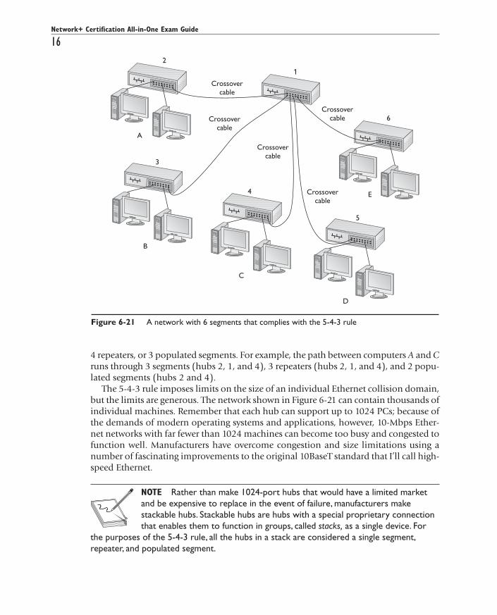
4 repeaters, or 3 populated segments. For example, the path between computers A and Cruns through 3 segments (hubs 2, 1, and 4), 3 repeaters (hubs 2, 1, and 4), and 2 popu-lated segments (hubs 2 and 4).
The 5-4-3 rule imposes limits on the size of an individual Ethernet collision domain,but the limits are generous. The network shown in Figure 6-21 can contain thousands ofindividual machines. Remember that each hub can support up to 1024 PCs; because ofthe demands of modern operating systems and applications, however, 10-Mbps Ether-net networks with far fewer than 1024 machines can become too busy and congested tofunction well. Manufacturers have overcome congestion and size limitations using anumber of fascinating improvements to the original 10BaseT standard that I’ll call high-speed Ethernet.
NOTE Rather than make 1024-port hubs that would have a limited marketand be expensive to replace in the event of failure, manufacturers makestackable hubs. Stackable hubs are hubs with a special proprietary connectionthat enables them to function in groups, called stacks, as a single device. For
the purposes of the 5-4-3 rule, all the hubs in a stack are considered a single segment,repeater, and populated segment.
Network+ Certification All-in-One Exam Guide
16
All-In-One / Network+ Certification All-in-One Exam Guide / Meyers / 225345-2 / Chapter 6
Figure 6-21 A network with 6 segments that complies with the 5-4-3 rule
P:\010Comp\All-in-1\345-2\ch06.vpFriday, September 17, 2004 3:26:07 PM
Color profile: Generic CMYK printer profileComposite Default screen

Chapter 6: Modern Ethernet
17
All-In-One / Network+ Certification All-in-One Exam Guide / Meyers / 225345-2 / Chapter 6
PA
RT
II
High-Speed EthernetAs any fighter pilot will tell you, sometimes you just feel the need—the need for speed.While plain-vanilla Ethernet performs well enough for basic file and print sharing, to-day’s more demanding network applications, such as Lotus Notes, SAP, and MicrosoftExchange, as well as other vital office applications like Half-Life and Unreal Tourna-ment, can quickly saturate a network running at 10 Mbps. Fortunately, those crazy kidsover at the IEEE keep expanding the standard, providing the network tech in thetrenches with new tools that provide additional bandwidth. These cool new tools in-clude Fast Ethernet, full-duplex Ethernet, Gigabit Ethernet, and switched Ethernet.
100Base EthernetFast Ethernet is not a single technology. The term Fast Ethernet refers to any of severalEthernet flavors that operate at 100 Mbps. Rather than limiting Ethernet to a single high-speed solution, the IEEE endorsed multiple standards for Fast Ethernet and allowed themarketplace to choose from among them. The major variations include 100BaseT and100BaseFX.
100BaseTThe IEEE supports two variations of 100BaseT: 100BaseTX and 100BaseT4. Both flavorsphysically resemble 10BaseT, using a star bus topology and connecting to hubs withUTP cabling. The 100 in their names reflects the fact that the cable connecting a device toa hub can send data at speeds up to 100 Mbps. The difference between 100BaseTX and100BaseT4 lies in the quality of the cable required. 100BaseTX requires CAT 5 or bettercabling to achieve a speed of 100 Mbps using only two pairs of wires. Like 10BaseT,100BaseTX ignores the remaining two pairs. 100BaseT4 uses all four pairs to achieve 100Mbps performance using lower quality CAT 3 or better cabling. Think of the cable as ahighway: 100BaseTX increases capacity by raising the speed limit, while 100BaseT4 in-creases capacity by adding additional lanes.
NOTE 100BaseVG, also known as 100BaseVGAnyLAN, is not a flavor ofEthernet. Designed to run over Category 3 (voice grade) cabling, it does notuse CSMA/CD to determine access to the cable. The IEEE 802.12 committeecontrols the standards for 100BaseVG. As the popularity of 100BaseTX has
grown, the importance of competitors like 100BaseVG has diminished dramatically.
Both 100BaseTX and 100BaseT4 allow organizations to take advantage of their exist-ing UTP cabling. If the existing UTP wiring was properly installed, you can upgrade anetwork from 10BaseT simply by replacing hubs and network cards, with no recablingrequired.
100BaseTX and 100BaseT4 are not interchangeable. If you have 100BaseTX hubs, thenyou must also have 100BaseTX NICs. Equally, if your hub is 100BaseT4, then you musthave 100BaseT4 NICs. Over the past few years, 100BaseTX has pushed 100BaseT4 out ofthe market so completely that devices labeled as 100BaseTX are now practically impossi-ble to find. When you purchase 100BaseTX equipment now, it usually just says 100BaseT.
P:\010Comp\All-in-1\345-2\ch06.vpFriday, September 17, 2004 3:26:07 PM
Color profile: Generic CMYK printer profileComposite Default screen
UTP cabling cannot meet the needs of every organization, however, for three key rea-sons. First, the 100-meter distance limitation of UTP-based networks is inadequate fornetworks covering large buildings or campuses. Second, UTP’s lack of electrical shield-ing makes it a poor choice for networks functioning in locations with high levels of elec-trical interference. Finally, the Maxwell Smarts and James Bonds of the world find UTPcabling (and copper cabling in general) easy to tap, making it an inappropriate choicefor high-security environments. To address these issues, the IEEE 802.3 standard pro-vides for a flavor of 100-megabit Ethernet using fiber-optic cable, called 100BaseFX.
NOTE Even though shielded twisted-pair cabling is available, its use is rare.Most installations will use fiber-optic cable in situations where UTP is notadequate.
100BaseFXThe 100BaseFX standard saw quite a bit of interest for years, as it combined the highspeed of 100Base Ethernet with the reliability of fiber optics. Outwardly, 100BaseFXlooks exactly like 10BaseFL: both use the same multimode fiber-optic cabling, and bothuse SC or ST connectors. 100BaseFX is an improvement over 10BaseFL, however, sup-porting a maximum cable length of 400 meters.
Migrating to Fast EthernetUpgrading an entire network to 100BaseTX can be a daunting task. 100BaseTX requiresnew hubs, new NICs, and often upgrades to the existing cabling. For organizations withmore than a few machines, upgrading every node can take months or even years. Fortu-nately, the conversion can be done slowly. In fact, organizations that want to do so canpurchase 10/100BaseT devices. A 10/100BaseT device automatically functions as a100BaseT device when plugged into another 10/100BaseT or 100BaseT device, but func-tions as a 10BaseT device when plugged into another 10BaseT device. The existence ofthese hybrid devices enables organizations to roll out 100BaseT in batches, providinghigh-speed access to the machines that need it.
Gigabit EthernetFor the true speed junkie, an even more powerful version of Ethernet exists: GigabitEthernet. The IEEE has approved two different versions of Gigabit Ethernet. The first ver-sion, published under the 802.3z standard and known as 1000BaseX, is divided into aseries of standards, with names such as 1000BaseCX, 1000BaseSX, and 1000BaseLX. The802.3ab standard defines a single UTP solution called 1000BaseT. Of all these Gigabitstandards, 1000BaseT has come out as the dominant Gigabit Ethernet standard.
1000BaseT uses four-pair UTP cabling to achieve gigabit performance. Like 10BaseTand 100BaseT, 1000BaseT has a maximum cable length of 100 meters. 1000BaseT con-nections and ports look exactly like the ones on a 10BaseT or 100BaseT network.
Network+ Certification All-in-One Exam Guide
18
All-In-One / Network+ Certification All-in-One Exam Guide / Meyers / 225345-2 / Chapter 6
P:\010Comp\All-in-1\345-2\ch06.vpFriday, September 17, 2004 3:26:08 PM
Color profile: Generic CMYK printer profileComposite Default screen

NOTE The term Gigabit Ethernet is more commonly used than 1000BaseT.
The 802.3z standards require a bit more discussion. Let’s look at each of these solu-tions in detail to see how they work.
1000BaseCX uses a unique shielded cable known as twinaxial cable(Figure 6-22). Twinaxial cables are special shielded 150-Ohm cables with a length limitof only 25 meters. 1000BaseCX has made little progress in the Gigabit Ethernet market.1000BaseCX falls under the IEEE 802.3z standard.
Many networks upgrading to Gigabit Ethernet use the 1000BaseSXstandard. 1000BaseSX uses multimode fiber-optic cabling to connect systems, with agenerous maximum cable length of over 500 meters; the exact length is left up to the var-ious manufacturers. 1000BaseSX uses an 850-nm (nanometer) wavelength LED to trans-mit light on the fiber optic cable. Like 1000BaseCX, 1000BaseSX comes under the802.3z standard. 1000BaseSX devices look exactly like the 100BaseFX products you readabout earlier in this chapter, but they rely exclusively on the SC type of connector.
1000BaseLX is the long-distance carrier for Gigabit Ethernet. 1000BaseLXuses single-mode (laser) cables to shoot data at distances up to five kilometers—andsome manufacturers use special repeaters to increase that to distances as great as 70 kilo-meters! The Ethernet folks are trying to position this as the Ethernet backbone of the fu-ture, and already some large carriers are beginning to adopt 1000BaseLX. You may liveyour whole life and never see a 1000BaseLX device, but odds are good that you will en-counter connections that use such devices in the near future. 1000BaseLX looks like1000BaseSX, and is also part of the 802.3z standard.
New Fiber ConnectorsAround the time that Gigabit Ethernet first stated to appear, two problems began to sur-face with ST and SC connectors. First, ST connectors are relatively large, twist-on connec-tors, requiring the installer to twist the cable when inserting or removing a cable.Twisting is not a popular action with fiber-optic cables, as the delicate fibers may frac-ture. Also, big-fingered techs have a problem with ST connectors if the connectors are
Chapter 6: Modern Ethernet
19
All-In-One / Network+ Certification All-in-One Exam Guide / Meyers / 225345-2 / Chapter 6
PA
RT
II
Figure 6-22Twinaxial cable
P:\010Comp\All-in-1\345-2\ch06.vpFriday, September 17, 2004 3:26:08 PM
Color profile: Generic CMYK printer profileComposite Default screen
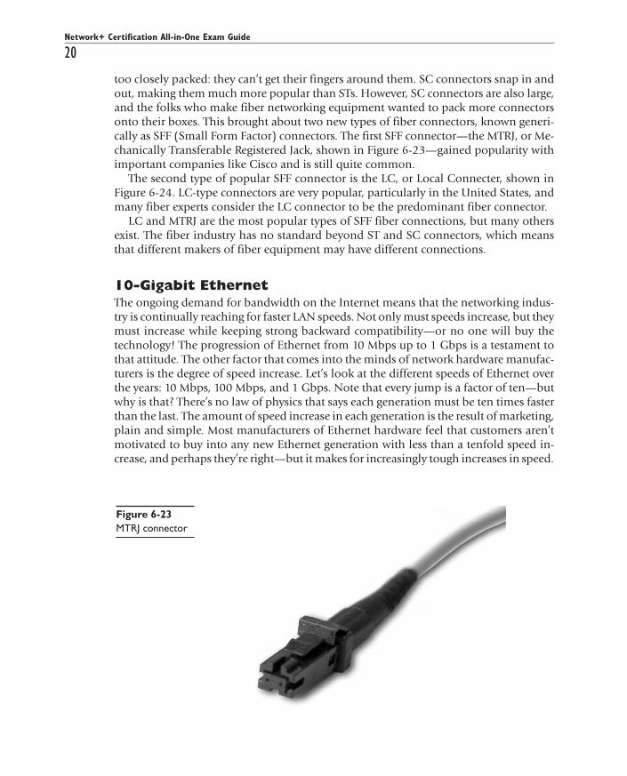
too closely packed: they can’t get their fingers around them. SC connectors snap in andout, making them much more popular than STs. However, SC connectors are also large,and the folks who make fiber networking equipment wanted to pack more connectorsonto their boxes. This brought about two new types of fiber connectors, known generi-cally as SFF (Small Form Factor) connectors. The first SFF connector—the MTRJ, or Me-chanically Transferable Registered Jack, shown in Figure 6-23—gained popularity withimportant companies like Cisco and is still quite common.
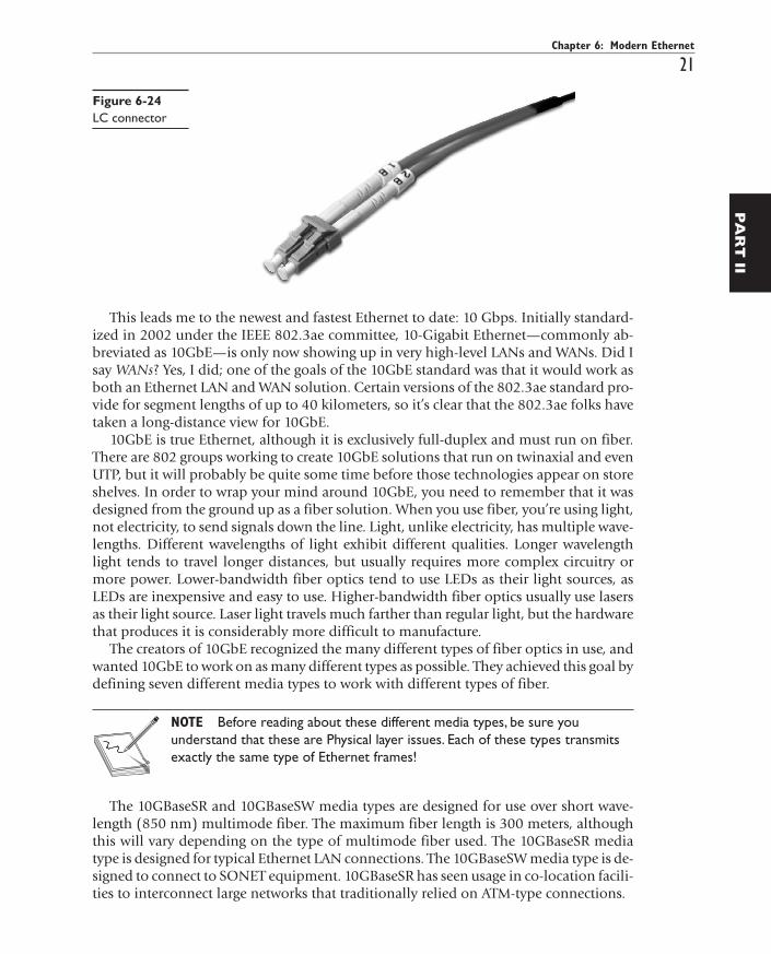
The second type of popular SFF connector is the LC, or Local Connecter, shown inFigure 6-24. LC-type connectors are very popular, particularly in the United States, andmany fiber experts consider the LC connector to be the predominant fiber connector.
LC and MTRJ are the most popular types of SFF fiber connections, but many othersexist. The fiber industry has no standard beyond ST and SC connectors, which meansthat different makers of fiber equipment may have different connections.
10-Gigabit EthernetThe ongoing demand for bandwidth on the Internet means that the networking indus-try is continually reaching for faster LAN speeds. Not only must speeds increase, but theymust increase while keeping strong backward compatibility—or no one will buy thetechnology! The progression of Ethernet from 10 Mbps up to 1 Gbps is a testament tothat attitude. The other factor that comes into the minds of network hardware manufac-turers is the degree of speed increase. Let’s look at the different speeds of Ethernet overthe years: 10 Mbps, 100 Mbps, and 1 Gbps. Note that every jump is a factor of ten—butwhy is that? There’s no law of physics that says each generation must be ten times fasterthan the last. The amount of speed increase in each generation is the result of marketing,plain and simple. Most manufacturers of Ethernet hardware feel that customers aren’tmotivated to buy into any new Ethernet generation with less than a tenfold speed in-crease, and perhaps they’re right—but it makes for increasingly tough increases in speed.
Network+ Certification All-in-One Exam Guide
20
All-In-One / Network+ Certification All-in-One Exam Guide / Meyers / 225345-2 / Chapter 6
Figure 6-23MTRJ connector
P:\010Comp\All-in-1\345-2\ch06.vpFriday, September 17, 2004 3:26:09 PM
Color profile: Generic CMYK printer profileComposite Default screen
Chapter 6: Modern Ethernet
21
All-In-One / Network+ Certification All-in-One Exam Guide / Meyers / 225345-2 / Chapter 6
PA
RT
II
This leads me to the newest and fastest Ethernet to date: 10 Gbps. Initially standard-ized in 2002 under the IEEE 802.3ae committee, 10-Gigabit Ethernet—commonly ab-breviated as 10GbE—is only now showing up in very high-level LANs and WANs. Did Isay WANs? Yes, I did; one of the goals of the 10GbE standard was that it would work asboth an Ethernet LAN and WAN solution. Certain versions of the 802.3ae standard pro-vide for segment lengths of up to 40 kilometers, so it’s clear that the 802.3ae folks havetaken a long-distance view for 10GbE.
10GbE is true Ethernet, although it is exclusively full-duplex and must run on fiber.There are 802 groups working to create 10GbE solutions that run on twinaxial and evenUTP, but it will probably be quite some time before those technologies appear on storeshelves. In order to wrap your mind around 10GbE, you need to remember that it wasdesigned from the ground up as a fiber solution. When you use fiber, you’re using light,not electricity, to send signals down the line. Light, unlike electricity, has multiple wave-lengths. Different wavelengths of light exhibit different qualities. Longer wavelengthlight tends to travel longer distances, but usually requires more complex circuitry ormore power. Lower-bandwidth fiber optics tend to use LEDs as their light sources, asLEDs are inexpensive and easy to use. Higher-bandwidth fiber optics usually use lasersas their light source. Laser light travels much farther than regular light, but the hardwarethat produces it is considerably more difficult to manufacture.
The creators of 10GbE recognized the many different types of fiber optics in use, andwanted 10GbE to work on as many different types as possible. They achieved this goal bydefining seven different media types to work with different types of fiber.
NOTE Before reading about these different media types, be sure youunderstand that these are Physical layer issues. Each of these types transmitsexactly the same type of Ethernet frames!
The 10GBaseSR and 10GBaseSW media types are designed for use over short wave-length (850 nm) multimode fiber. The maximum fiber length is 300 meters, althoughthis will vary depending on the type of multimode fiber used. The 10GBaseSR mediatype is designed for typical Ethernet LAN connections. The 10GBaseSW media type is de-signed to connect to SONET equipment. 10GBaseSR has seen usage in co-location facili-ties to interconnect large networks that traditionally relied on ATM-type connections.
Figure 6-24LC connector
P:\010Comp\All-in-1\345-2\ch06.vpFriday, September 17, 2004 3:26:09 PM
Color profile: Generic CMYK printer profileComposite Default screen
The 10GBaseLR and 10GBaseLW media types are designed for use over long wavelength(1310 nm) single-mode fiber. The maximum fiber length is 10 kilometers, although thiswill vary depending on the type of single-mode fiber used. The 10GBaseLR media type isdesigned for typical Ethernet LAN connections. The 10GBaseLW media type is designed toconnect to SONET equipment. 10GBaseLR is the most popular 10GbE media type.
The 10GBaseER and 10GBaseEW media types are designed for use over extra longwavelength (1550 nm) single-mode fiber. The maximum fiber length is 40 kilometers,although this will vary depending on the type of single-mode fiber used. The 10GBaseERmedia type is designed for typical Ethernet LAN connections, while the 10GBaseEW me-dia type is designed to connect to SONET equipment. 10GBaseER is expensive and hasonly seen substantial use in long-distance interconnects to replace a leased line.
10GBaseLX4 is the odd duck. The previous six media types all use a single wavelengthof light, sending a serial signal. This media type uses wave division multiplexing tech-nology, using four or more wavelengths of light over a single pair of either single-modeor multimode fiber-optic cable. 10GBaseLX4 has had little industry support.
10GBaseSW, 10GBaseLW, and 10GBaseEW only exist to allow 10GbE connectionsover existing SONET lines; see Chapter 16, “Remote Connectivity,” for details onSONET. Many network experts see these 10GbE-over-SONET solutions as little morethan short-term solutions until 10GbE lines replace the SONET lines. Replacing SONETlines with 10GbE provides two benefits: first, you no longer need equipment on eachend to convert Ethernet to SONET and back again. Second, because SONET is no longerneeded, anyone willing to make a large enough up-front investment can own their ownnative Ethernet fiber cables, in WAN and MAN situations where typically they would beat the mercy of the local SONET carriers’ lease rates.
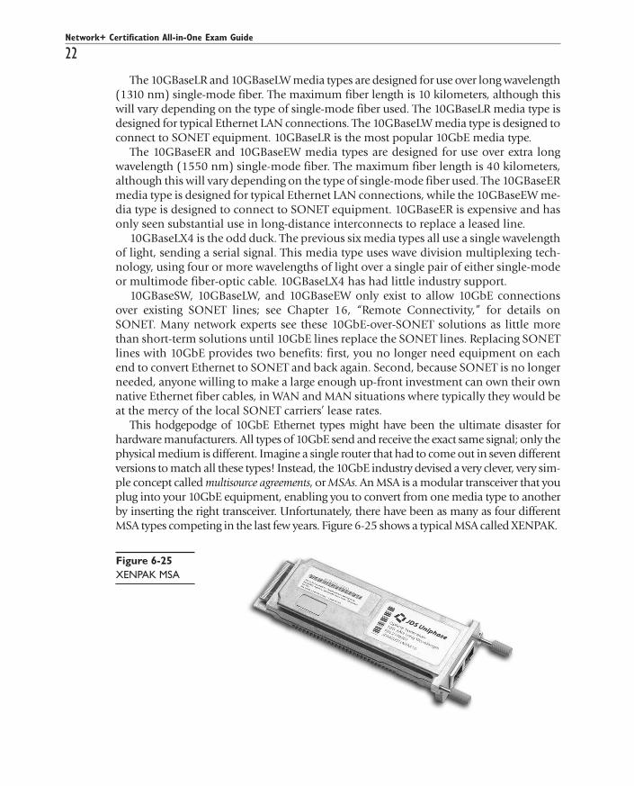
This hodgepodge of 10GbE Ethernet types might have been the ultimate disaster forhardware manufacturers. All types of 10GbE send and receive the exact same signal; only thephysical medium is different. Imagine a single router that had to come out in seven differentversions to match all these types! Instead, the 10GbE industry devised a very clever, very sim-ple concept called multisource agreements, or MSAs. An MSA is a modular transceiver that youplug into your 10GbE equipment, enabling you to convert from one media type to anotherby inserting the right transceiver. Unfortunately, there have been as many as four differentMSA types competing in the last few years. Figure 6-25 shows a typical MSA called XENPAK.
Network+ Certification All-in-One Exam Guide
22
All-In-One / Network+ Certification All-in-One Exam Guide / Meyers / 225345-2 / Chapter 6
Figure 6-25XENPAK MSA
P:\010Comp\All-in-1\345-2\ch06.vpFriday, September 17, 2004 3:26:10 PM
Color profile: Generic CMYK printer profileComposite Default screen

NOTE Not all 10GbE manufacturers use MSAs in their equipment.
For now, 10GbE equipment is the exclusive domain of extremely high-bandwidthLANs and WANs, including parts of the “big pipe” Internet connections.
Switched EthernetDon’t feel like upgrading all your NICs and hubs to get more speed? How would youlike to dramatically improve performance just by replacing your hub? Switched Ethernetmay be the solution for you! An Ethernet switch is a special hub that can place some de-vices into their own collision domains. In essence, an Ethernet switch is a hub with abridge built in. Switches, like bridges, work at the OSI Data Link layer, or Layer 2—in fact,they’re often referred to as Layer 2 switches. Physically, an Ethernet switch looks muchlike any other Ethernet hub, except for the addition of one or more switched ports (seeFigure 6-26). Logically, an Ethernet switch puts each device plugged into one of itsswitched ports into its own collision domain. As one system begins to send data to an-other system, a switch looks at the incoming MAC addresses and creates a single colli-sion domain (see Figure 6-27).
Using an Ethernet switch provides two benefits. First, if both the sender and the re-ceiver are on their own switched ports, the full bandwidth of that connection (10, 100,or 1000 megabits) is available to them—no other machine can cause a collision. Second,the switch can act as a buffer, enabling devices running at different speeds to communicate.Without this buffering capability, a Gigabit Ethernet card would overload a slow NIC.
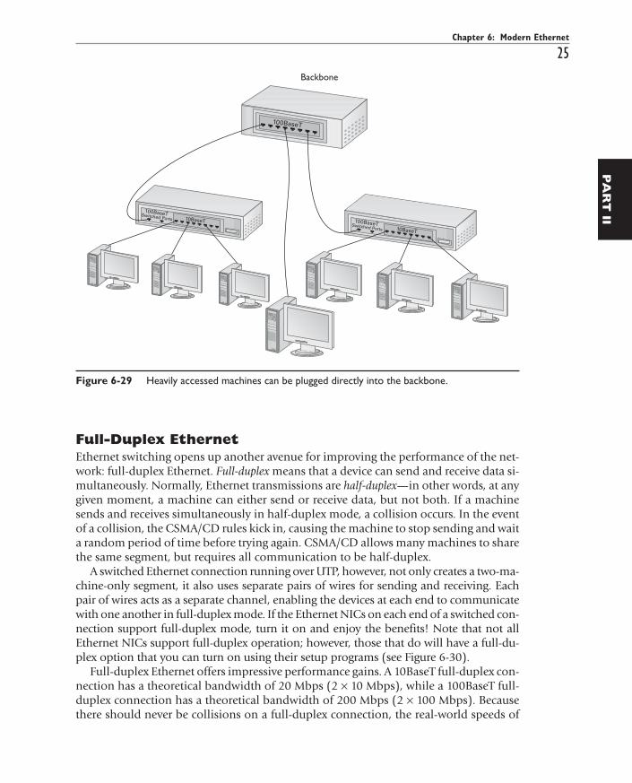
Ethernet switches can also connect segments to a backbone. A backbone is a segmentthat connects other segments. Most backbones are lightly populated or unpopulated. Inmost cases, a backbone runs at a higher speed than the segments it connects. Figure 6-28shows a network that supplies 10BaseT to networked desktops, and connects the hubs toa 100BaseT backbone segment. In some cases, heavily accessed machines, such as fileservers, plug directly into the backbone, as shown in Figure 6-29.
Chapter 6: Modern Ethernet
23
All-In-One / Network+ Certification All-in-One Exam Guide / Meyers / 225345-2 / Chapter 6
PA
RT
II
Figure 6-26An eight-portswitch with twoswitched ports
P:\010Comp\All-in-1\345-2\ch06.vpFriday, September 17, 2004 3:26:10 PM
Color profile: Generic CMYK printer profileComposite Default screen

Network+ Certification All-in-One Exam Guide
24
All-In-One / Network+ Certification All-in-One Exam Guide / Meyers / 225345-2 / Chapter 6
Figure 6-27 Devices plugged into switched ports are isolated on their own collision domains.
Figure 6-28 Desktop machines run at 10 Mbps, but the backbone runs at 100 Mbps.
P:\010Comp\All-in-1\345-2\ch06.vpFriday, September 17, 2004 3:26:11 PM
Color profile: Generic CMYK printer profileComposite Default screen
Chapter 6: Modern Ethernet
25
All-In-One / Network+ Certification All-in-One Exam Guide / Meyers / 225345-2 / Chapter 6
PA
RT
II
Full-Duplex EthernetEthernet switching opens up another avenue for improving the performance of the net-work: full-duplex Ethernet. Full-duplex means that a device can send and receive data si-multaneously. Normally, Ethernet transmissions are half-duplex—in other words, at anygiven moment, a machine can either send or receive data, but not both. If a machinesends and receives simultaneously in half-duplex mode, a collision occurs. In the eventof a collision, the CSMA/CD rules kick in, causing the machine to stop sending and waita random period of time before trying again. CSMA/CD allows many machines to sharethe same segment, but requires all communication to be half-duplex.
A switched Ethernet connection running over UTP, however, not only creates a two-ma-chine-only segment, it also uses separate pairs of wires for sending and receiving. Eachpair of wires acts as a separate channel, enabling the devices at each end to communicatewith one another in full-duplex mode. If the Ethernet NICs on each end of a switched con-nection support full-duplex mode, turn it on and enjoy the benefits! Note that not allEthernet NICs support full-duplex operation; however, those that do will have a full-du-plex option that you can turn on using their setup programs (see Figure 6-30).
Full-duplex Ethernet offers impressive performance gains. A 10BaseT full-duplex con-nection has a theoretical bandwidth of 20 Mbps (2 × 10 Mbps), while a 100BaseT full-duplex connection has a theoretical bandwidth of 200 Mbps (2 × 100 Mbps). Becausethere should never be collisions on a full-duplex connection, the real-world speeds of
Figure 6-29 Heavily accessed machines can be plugged directly into the backbone.
P:\010Comp\All-in-1\345-2\ch06.vpFriday, September 17, 2004 3:26:11 PM
Color profile: Generic CMYK printer profileComposite Default screen

Network+ Certification All-in-One Exam Guide
26
All-In-One / Network+ Certification All-in-One Exam Guide / Meyers / 225345-2 / Chapter 6
full-duplex Ethernet approach these theoretical maximums. Unfortunately, many older10BaseT devices do not support full-duplex operation; however, most 100Base and1000Base Ethernet standards require full-duplex operation, making it an assumed func-tion on those devices.
TIP For the exam, know that in half-duplex communication, a device cannotsend when it is receiving and vice versa. In full-duplex communication,however, a device can send and receive at the same time.
Here’s a thought: if a switched network creates separate collision domains for all thenodes, does the 5-4-3 rule still apply? Good question! If you answered “No,” that’s evenbetter! Once you start using switches, the entire concept of 5-4-3 goes out the window;there are no limitations due to collisions, except within individual collision domains.
The wonderful benefits of switches make them extremely common today. By replac-ing a hub with a switch, your network can take advantage of collision-free, full-duplexcommunication to achieve much higher speeds.
ConclusionWhile 10Base2 and 10Base5 soldier on in some networks, the use of the star bus hybridtopology for UTP- and fiber-optic-based Ethernet networks enables techs to build morerobust and flexible networks. The capability to use high-speed segments, full-duplex op-eration, bridging, routing, and switching gives the network architect a full toolkit withwhich to build fast, stable networks. For all these reasons, UTP and fiber dominate thenetworking industry today, leaving coaxial to dwindle away.
Figure 6-30If a card supportsfull-duplex mode,its setup programwill have anoption to switchbetween half- andfull-duplex.
P:\010Comp\All-in-1\345-2\ch06.vpFriday, September 17, 2004 3:26:12 PM
Color profile: Generic CMYK printer profileComposite Default screen
Chapter 6: Modern Ethernet
27
All-In-One / Network+ Certification All-in-One Exam Guide / Meyers / 225345-2 / Chapter 6
PA
RT
II
Chapter Review
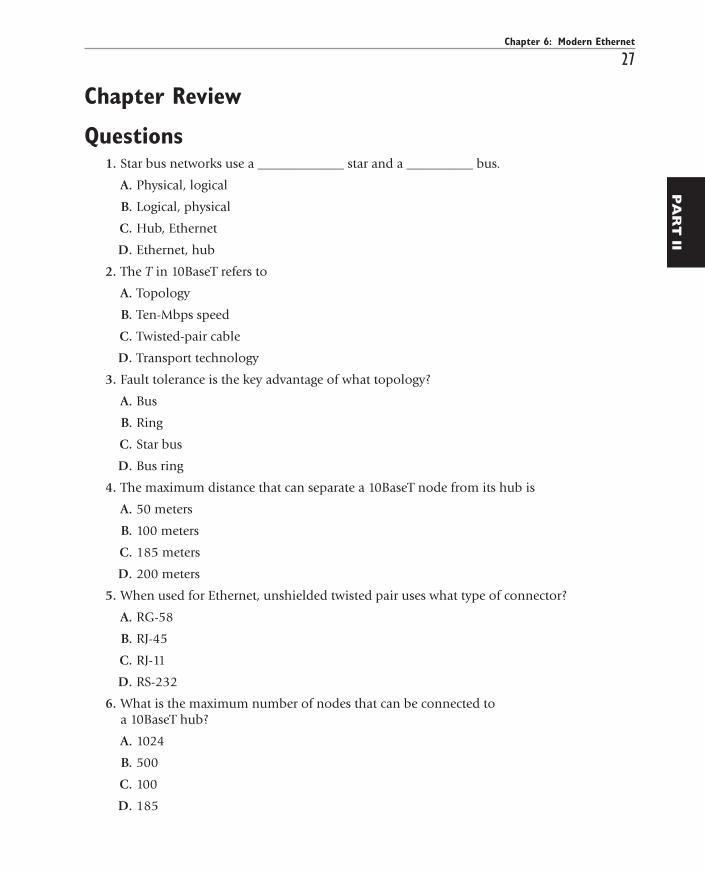
Questions1. Star bus networks use a _____________ star and a __________ bus.
A. Physical, logical
B. Logical, physical
C. Hub, Ethernet
D. Ethernet, hub
2. The T in 10BaseT refers to
A. Topology
B. Ten-Mbps speed
C. Twisted-pair cable
D. Transport technology
3. Fault tolerance is the key advantage of what topology?
A. Bus
B. Ring
C. Star bus
D. Bus ring
4. The maximum distance that can separate a 10BaseT node from its hub is
A. 50 meters
B. 100 meters
C. 185 meters
D. 200 meters
5. When used for Ethernet, unshielded twisted pair uses what type of connector?
A. RG-58
B. RJ-45
C. RJ-11
D. RS-232
6. What is the maximum number of nodes that can be connected toa 10BaseT hub?
A. 1024
B. 500
C. 100
D. 185
P:\010Comp\All-in-1\345-2\ch06.vpFriday, September 17, 2004 3:26:12 PM
Color profile: Generic CMYK printer profileComposite Default screen
Network+ Certification All-in-One Exam Guide
28
All-In-One / Network+ Certification All-in-One Exam Guide / Meyers / 225345-2 / Chapter 6
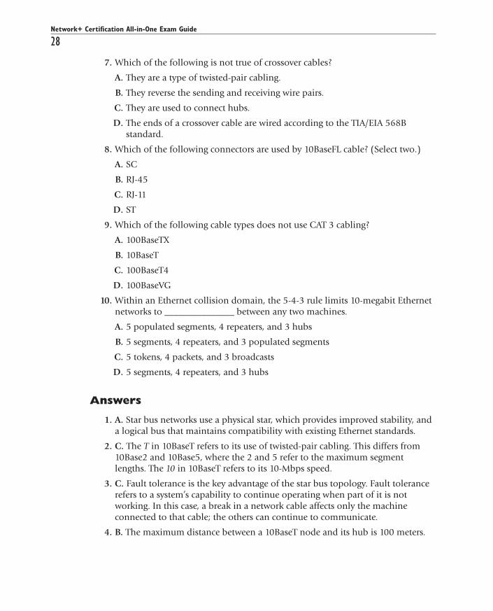
7. Which of the following is not true of crossover cables?
A. They are a type of twisted-pair cabling.
B. They reverse the sending and receiving wire pairs.
C. They are used to connect hubs.
D. The ends of a crossover cable are wired according to the TIA/EIA 568Bstandard.
8. Which of the following connectors are used by 10BaseFL cable? (Select two.)
A. SC
B. RJ-45
C. RJ-11
D. ST
9. Which of the following cable types does not use CAT 3 cabling?
A. 100BaseTX
B. 10BaseT
C. 100BaseT4
D. 100BaseVG
10. Within an Ethernet collision domain, the 5-4-3 rule limits 10-megabit Ethernetnetworks to _______________ between any two machines.
A. 5 populated segments, 4 repeaters, and 3 hubs
B. 5 segments, 4 repeaters, and 3 populated segments
C. 5 tokens, 4 packets, and 3 broadcasts
D. 5 segments, 4 repeaters, and 3 hubs
Answers
1. A. Star bus networks use a physical star, which provides improved stability, anda logical bus that maintains compatibility with existing Ethernet standards.
2. C. The T in 10BaseT refers to its use of twisted-pair cabling. This differs from10Base2 and 10Base5, where the 2 and 5 refer to the maximum segmentlengths. The 10 in 10BaseT refers to its 10-Mbps speed.
3. C. Fault tolerance is the key advantage of the star bus topology. Fault tolerancerefers to a system’s capability to continue operating when part of it is notworking. In this case, a break in a network cable affects only the machineconnected to that cable; the others can continue to communicate.
4. B. The maximum distance between a 10BaseT node and its hub is 100 meters.
P:\010Comp\All-in-1\345-2\ch06.vpFriday, September 17, 2004 3:26:12 PM
Color profile: Generic CMYK printer profileComposite Default screen

5. B. UTP cable uses an RJ-45 connector when used for Ethernet. RG-58 is the typeof coaxial cable used with 10Base2. RJ-11 is the standard four-wire connectorused for regular phone lines. RS-232 is a standard for serial connectors.
6. A. A 10BaseT hub can connect no more than 1024 nodes (computers).
7. D. One end of a crossover cable is wired according to the TIA/EIA 568Bstandard; the other is wired according to the TIA/EIA 586A standard. This iswhat crosses the wire pairs and enables two hubs to communicate withoutcolliding.
8. A, D. 10BaseFL uses two types of fiber-optic connectors called SC and STconnectors.
9. A. 100BaseTX requires CAT 5 or better cabling. 10BaseT, 100BaseT4, and100BaseVG can all use CAT 3 cabling.
10. B. Within a collision domain, the 5-4-3 rule limits 10-megabit Ethernetnetworks to 5 segments, 4 repeaters, and 3 populated segments betweenany two machines.
Chapter 6: Modern Ethernet
29
All-In-One / Network+ Certification All-in-One Exam Guide / Meyers / 225345-2 / Chapter 6
PA
RT
II
P:\010Comp\All-in-1\345-2\ch06.vpFriday, September 17, 2004 3:26:12 PM
Color profile: Generic CMYK printer profileComposite Default screen

All-In-One / Network+ Certification All-in-One Exam Guide / Meyers / 225345-2 /Blind Folio 30
P:\010Comp\All-in-1\345-2\ch06.vpFriday, September 17, 2004 3:26:12 PM
Color profile: Generic CMYK printer profileComposite Default screen