chapter one 1 - wordpress.com · plastic hinges and collapse mechanisms 6. ... chapter of the...
TRANSCRIPT
Reinforced Concrete Structures 2
(CEng-3122)
School of Civil and Environmental Engineering
Concrete Material and Structures Chair
March 25, 2016
Addis Ababa institute of Technology
1Chapter OnePlastic Moment Redistribution
Presentation Outline
1. Introduction
2. Moment Curvature Relationship
3. Rotation Capacity
4. Continuous Beams
5. Plastic Hinges and Collapse Mechanisms
6. Moment Redistribution Content
March 25, 2016Addis Ababa institute of Technology
2
Introduction
• Analysis of Reinforced Concrete Structures
• Methods of Analysis Allowed in EC-2
March 25, 2016Addis Ababa institute of Technology
3

Analysis of RC Structures
March 25, 2016Addis Ababa institute of Technology
4
• The purpose of any analysis is to know how the structure responds to a given loading and
there by evaluate the stresses and deformations.
Given: the following sets of parameters
Back to Input
Above Below
Show positive
Geom
etr
y, L
oadin
g a
nd
Str
uctu
ral Layout
Mate
rial Pro
pert
y
Carrying out Elastic Analysis: Results ...
#N/A60.17
-65.58
-80.00
-60.00
-40.00
-20.00
0.00
20.00
40.00
60.00
80.00
0 5 10 15 20 25
Moment, kN-m
#N/A
61.4
-70.9-80.0
-60.0
-40.0
-20.0
0.0
20.0
40.0
60.0
80.0
0 5 10 15 20 25
Shear, kN
#N/A
0.25
-1.96
-2.5
-2.0
-1.5
-1.0
-0.5
0.0
0.5
0 5 10 15 20 25
Deflections, mm
#N/A
0.00085
-0.00118
0.00
0.00
0.00
0.00
0.00
0.00
0 5 10 15 20 25
Rotations, rad
Stresses
DeformationSo far in the course analysis
are based on linear elastic
theory.

Analysis of RC Structures
March 25, 2016Addis Ababa institute of Technology
5
Most reinforced concrete structures are designed for internal forces found by elastic theory with
methods such as slope deflection, moment distribution, and matrix analysis.
There is an apparent inconsistency in determining the design moments based on an elastic
analysis, while doing the design based on a limit state design procedure, where the structural
design is based on inelastic section behavior.
Analysis
Factored loads
Elastic Analysis
Design
The tensile reinforcement is proportioned on the
assumption that its well beyond its yielding point at
failure. (Ductile Design or εs≥ 4.313‰)
Concrete stress distribution across the section is non-
linear.
Although the analysis and design basis
are contradictory, it will be a safe and
to a degree a conservative design.
Methods of Analysis Allowed in EC-2
March 25, 2016Addis Ababa institute of Technology
6
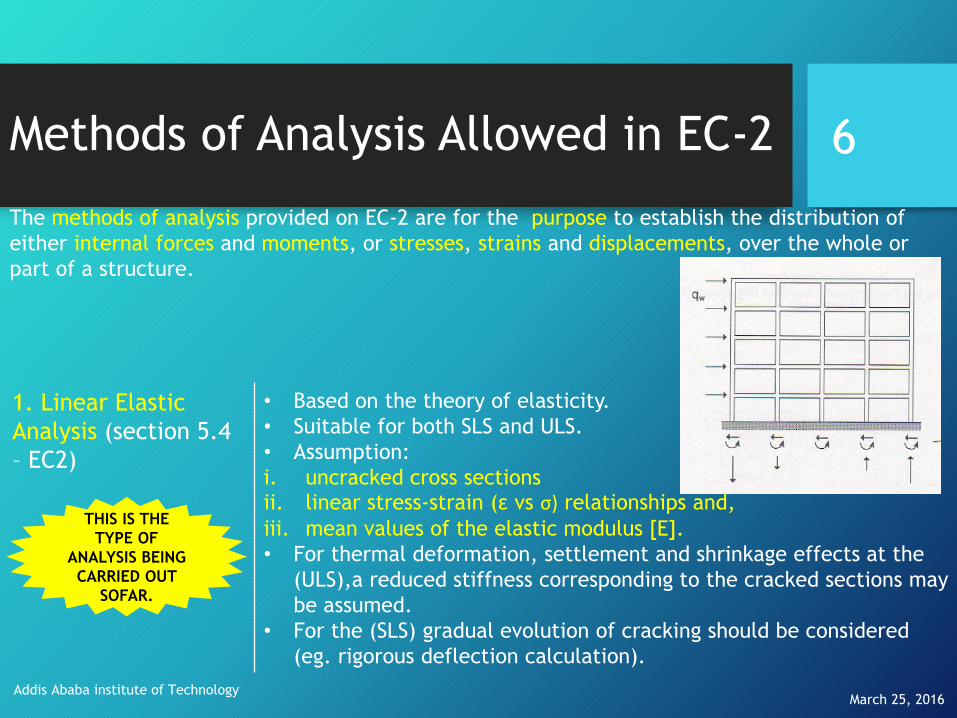
The methods of analysis provided on EC-2 are for the purpose to establish the distribution of
either internal forces and moments, or stresses, strains and displacements, over the whole or
part of a structure.
1. Linear Elastic
Analysis (section 5.4
– EC2)
• Based on the theory of elasticity.
• Suitable for both SLS and ULS.
• Assumption:
i. uncracked cross sectionsii. linear stress-strain (ε vs σ) relationships and,
iii. mean values of the elastic modulus [E].
• For thermal deformation, settlement and shrinkage effects at the
(ULS),a reduced stiffness corresponding to the cracked sections may
be assumed.
• For the (SLS) gradual evolution of cracking should be considered
(eg. rigorous deflection calculation).
THIS IS THE
TYPE OF
ANALYSIS BEING
CARRIED OUT
SOFAR.
Methods of Analysis Allowed in EC-2
March 25, 2016Addis Ababa institute of Technology
7
2. Linear Elastic
Analysis with Limited
Redistribution
(section 5.5)
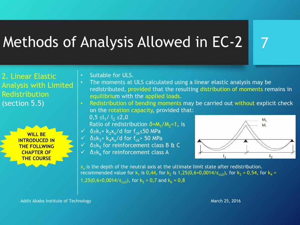
• Suitable for ULS.
• The moments at ULS calculated using a linear elastic analysis may be
redistributed, provided that the resulting distribution of moments remains in
equilibrium with the applied loads.
• Redistribution of bending moments may be carried out without explicit check
on the rotation capacity, provided that:
0,5 ≤l1/ l2 ≤2,0
Ratio of redistribution δ=M1/M2<1, is
δ≥k1+ k2xu/d for fck≤50 MPa
δ≥k3+ k4xu/d for fck> 50 MPa
δ≥k5 for reinforcement class B & C
δ≥k6 for reinforcement class A
xu is the depth of the neutral axis at the ultimate limit state after redistribution.
recommended value for k1 is 0,44, for k2 is 1,25(0,6+0,0014/εcu2), for k3 = 0,54, for k4 =
1,25(0,6+0,0014/εcu2), for k5 = 0,7 and k6 = 0,8
WILL BE
INTRODUCED IN
THE FOLLWING
CHAPTER OF
THE COURSE

Methods of Analysis Allowed in EC-2
March 25, 2016Addis Ababa institute of Technology
8
Plastic Analysis
(section 5.6)
• Suitable for ULS.
• Suitable for SLS if compatibility is ensured.
• When a beam yields in bending, an increase in curvature does not produce an
increase in moment resistance. Analysis of beams and structures made of such
flexural members is called Plastic Analysis.
• This is generally referred to as limit analysis, when applied to reinforced
concrete framed structures, and plastic analysis when applied to steel structures
non-Linear
Analysis
(section 5.7)
• Nonlinear analysis may be used for both ULS and SLS, provided that equilibrium
and compatibility are satisfied and an adequate non-linear behavior for materials
is assumed.
• The non-linear analysis procedures are more complex and therefore very time
consuming.
• The analysis maybe first Or second order.
WILL BE
INTRODUCED
IN THIS
CHAPTER OF
THE COURSE
IT IS
BEYOUND
THE SCOPE
OF THE
COURSE
Moment Curvature Relationship
• Curvature
• Basic Assumption and Consideration in Establishing the Moment Curvature Relationship
• Procedures in Establishing the Moment Curvature Relationship
March 25, 2016Addis Ababa institute of Technology
9

Curvature: Introduction
Beam loaded in bending. Segment of the beam loaded in bending.
Relationship between bending moment M and curvature K for beam with linear elastic homogeneous material.
But is Concrete a Homogenous, elastic material?
Then how do we determine the moment curvature relationship for it?
Why do we even bother compute the M – K relationship in the first place?
March 25, 2016Addis Ababa institute of Technology
10
For a beam with homogeneous cross-section, which is loaded in bending is shown below.
...... From Elastic Theory
Where:
E= the modulus of elasticity
I=the moment of inertia of the cross-section
K=the local curvature=1/R
MKE I

Curvature: RC section
March 25, 2016
Addis Ababa institute of
Technology
11
Reinforced concrete is not homogeneous because it is composed of steel and concrete
which have different values for the elastic modulus; however, it is possible to identify
an equivalent homogeneous concrete section with an equivalent moment of inertia.
This is done by means of
an equivalent transformed
cross section.
A3=(As2*(n-1))
As2
h A1
As1
A2=(As1*(n-1))
b
A3=(As2*(n-1))
As2 x
A1
h
As1
A2=(As1*n)
b
Uncracked
Fully-Cracked
To have the same
material property
of concrete across
the RC section the
reinforcement is
transformed in to
an equivalent
concrete area
using the modular
ratio n=Es/Ec

Curvature: RC section
It is important:
• to study the ductility of members
• to understand the development of plastic hinge, and
• to account for the redistribution of elastic moments that occurs in most reinforced concrete structures before collapse.
March 25, 2016Addis Ababa institute of Technology
12

Curvature: RC section
March 25, 2016Addis Ababa institute of Technology
13
The curve M-K may be calculated for every given cross-section in reinforced concrete;
this is typically done by the calculation of some salient points:
The curve M-K may be calculated for every given
cross-section in reinforced concrete; this is
typically done by the calculation of some salient
points:
A. M and K just before the appearance of the
flexural crack in the cross-section
B. M and K just after the appearance of the
flexural crack
C. M and K when steel start to yield
D. M and K when failure is reached (normally due
to the crushing of the compression concrete)
A Typical M-K diagram for a RC section.
A
C
B
D

Basic Assumption and Consideration in Establishing the M-K Relationship
March 25, 2016Addis Ababa institute of Technology
14
Basic
Assumptions
• Parabolic-rectangular stress block for concrete in compression
is assumed.
• Tensile strength of concrete is neglected.
• Plane section remains plane before and after bending.
• Elasto-Plastic stress strain relationship is assumed for
reinforcement steel in tension.
• Steel is perfectly bonded with concrete.
Basic
Considerations
• Equilibrium of forces shall be maintained.
• Compatibility of Strains shall be maintained.
• Stress-Strain relationship has to be satisfied .
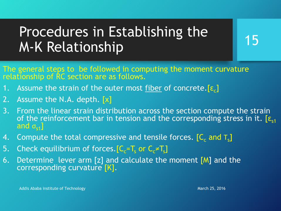
Procedures in Establishing the M-K Relationship
The general steps to be followed in computing the moment curvature relationship of RC section are as follows.
1. Assume the strain of the outer most fiber of concrete.[εc]
2. Assume the N.A. depth. [x]
3. From the linear strain distribution across the section compute the strain of the reinforcement bar in tension and the corresponding stress in it. [εs1and σs1]
4. Compute the total compressive and tensile forces. [Cc and Ts]
5. Check equilibrium of forces.[Cc=Ts or Cc≠Ts]
6. Determine lever arm [z] and calculate the moment [M] and the corresponding curvature [K].
March 25, 2016Addis Ababa institute of Technology
15
March 25, 2016Addis Ababa institute of Technology
16
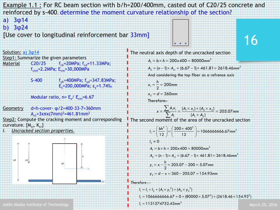
Example 1.1 : For RC beam section with b/h=200/400mm, casted out of C20/25 concrete and reinforced by s-400. determine the moment curvature relationship of the section?
a) 3φ14
b) 3φ24
[Use cover to longitudinal reinforcement bar 33mm]
Solution: a) 3φ14
Step1: Summarize the given parameters
Material C20/25 fck=20MPa; fcd=11.33MPa;
fctm=2.2MPa; Ecm=30,000MPa
S-400 fyk=400MPa; fyd=347.83MPa;
Es=200,000MPa; εy=1.74‰
Modular ratio, n= Es/ Ecm=6.67
Geometry d=h-cover- φ/2=400-33-7=360mm
As1=3xπx(7mm)2=461.81mm2
Step2: Compute the cracking moment and corresponding
curvature. [Mcr, Kcr]
I. Uncracked section properties.
The neutral axis depth of the uncracked section
The second moment of the area of the uncracked section
2
1
2
2 1
1
2
1 1 2 2
1 2
200 400 80000
( 1) (6.67 1) 461.81 2618.46
And considering the top fiber as a refrence axis
2002
360
Therefore:-
( ) ( ) 205.07
( )
s
i i
i
A b h x mm
A n A mm
hx mm
x d mm
A x A x A xx mm
A A A
3 34
1
2
2
1
2
2 1
1
2
200 4001066666666.67
12 12
0
200 400 80000
( 1) (6.67 1) 461.81 2618.46
205.07 200 5.072
360 205.07 154.93
s
bhI mm
I
A b h x mm
A n A mm
hy x mm
y d x mm
2 2
1 2 1 1 2 2
2 2
4
: -
( ) ( )
1066666666.67 0 (80000 5.07 ) (2618.46 154.93 )
1131574752.42
I
I
I
Therefore
I I I A y A y
I
I mm
March 25, 2016Addis Ababa institute of Technology
17
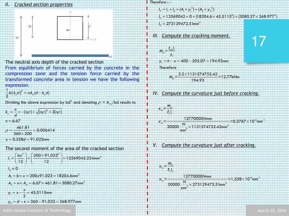
II. Cracked section properties
The neutral axis depth of the cracked section
From equilibrium of forces carried by the concrete in the
compression zone and the tension force carried by the
transformed concrete area in tension we have the following
expression.
The second moment of the area of the cracked section
2
1
2
s1
2
1( )
2
Dividing the above expression by bd and denoting = A /bd results in:
[ ] [ ] 2[ ]
6.67
461.810.006414
360 200
0.258 91.023
x s x
x
b k d nA d k d
xk n n nd
n
x d mm
III. Compute the cracking moment.
IV. Compute the curvature just before cracking.
V. Compute the curvature just after cracking.
cr
cr
=
400 205.07 194.93
Therefore
2.2 1131574752.42 = =12.77kNm
194.93
ctm I
t
t
f IM
y
y h x mm
M
2 2
1 2 1 1 2 2
2 2
4
: -
( ) ( )
12569042 0 (18204.6 45.5115 ) (3080.27 268.977 )
273129472.51
II
II
II
Therefore
I I I A y A y
I
I mm
cr
-6 -1
cr4
2
=
12770000= =0.3767 10 mm
30000 1131574752.42
cr
c I
M
E I
Nmm
Nmm
mm
cr
-6 -1
cr4
2
=
12770000= =1.558 10 mm
30000 273129472.51
cr
c II
M
E I
Nmm
Nmm
mm
3 34
1
2
2
1
2
2 1
1
2
200 91.02312569042.224
12 12
0
200 91.023 18204.6
6.67 461.81 3080.27
45.51152
360 91.023 268.977
s
bxI mm
I
A b x x mm
A n A mm
xy x mm
y d x mm

March 25, 2016Addis Ababa institute of
Technology
18
Step3: Compute the yielding moment and corresponding curvature.
[My, Ky]
Assuming 0< εcm <2‰ and from force equilibrium.
From the strain profile
From the simplified equations discussed in chapter two of RC-1
Step4: Compute the ultimate moment and corresponding
curvature. [Mu, Ku]
Assuming a compression failure εcm =3.5‰, εy < εs <25‰ and from
force equilibrium.
From the strain profile
From the simplified equations discussed in chapter two of RC-1
1
1 347.83
11.33 200 36
461.810.19
07
c cd s yd
s yd
c
cd
Cc Ts
f bd A f
A f
f bd
1.74
cm cmx
cm y cm
k
1 347.8461.810.19
3
11.33 200 3607
s yd
c
cd
A f
f bd
3.5
3.5x
s
k
(3 4) 20.101
2 (3 2)
cm cmc x
cm cm
k
( ) 360(1 0.101) 323.64cz d mm
1 51.99u s ydM A f z kNm
36 13.5 10
40.11 1087.26
cmu mmx mm
60.197
12
From the two equations above we can solve for to be 1.208. Assumption correct!
cmc cm x
cm
k
1.2080.410
1.208 1.74
360 0.410 147.6
x
x
k
x d k mm
80.145
4(6 )
cmc x
cm
k
( ) 360(1 0.145) 307.8cz d mm
1 49.442y s ydM A f z kNm
36 11.178 10
8.10 10145.44
cmy mmx mm
3 20.197
3
From the two equations above we can solve for to be 10.88 ... Assumption correct!
cmc x
cm
s
k
3.50.243
3.5 10.88
360 0.243 87.48
x
x
k
x d k mm

March 25, 2016Addis Ababa institute of Technology
19
Step5: Plot the moment vs curvature diagram.
Home take Bonus exam:
Redo example1.1 considering the role of concrete in the tension zone of the reinforced concrete section..
March 25, 2016Addis Ababa institute of Technology
20
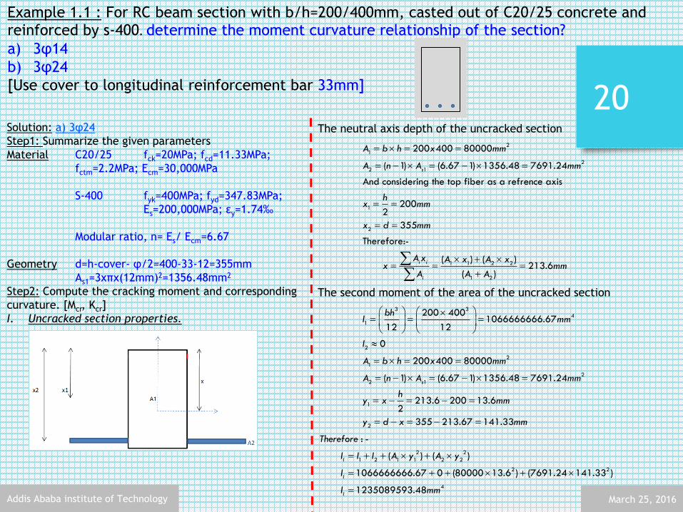
Example 1.1 : For RC beam section with b/h=200/400mm, casted out of C20/25 concrete and reinforced by s-400. determine the moment curvature relationship of the section?
a) 3φ14
b) 3φ24
[Use cover to longitudinal reinforcement bar 33mm]
Solution: a) 3φ24
Step1: Summarize the given parameters
Material C20/25 fck=20MPa; fcd=11.33MPa;
fctm=2.2MPa; Ecm=30,000MPa
S-400 fyk=400MPa; fyd=347.83MPa;
Es=200,000MPa; εy=1.74‰
Modular ratio, n= Es/ Ecm=6.67
Geometry d=h-cover- φ/2=400-33-12=355mm
As1=3xπx(12mm)2=1356.48mm2
Step2: Compute the cracking moment and corresponding
curvature. [Mcr, Kcr]
I. Uncracked section properties.
The neutral axis depth of the uncracked section
The second moment of the area of the uncracked section
2
1
2
2 1
1
2
1 1 2 2
1 2
200 400 80000
( 1) (6.67 1) 1356.48 7691.24
And considering the top fiber as a refrence axis
2002
355
Therefore:-
( ) ( ) 213.6
( )
s
i i
i
A b h x mm
A n A mm
hx mm
x d mm
A x A x A xx mm
A A A
3 34
1
2
2
1
2
2 1
1
2
200 4001066666666.67
12 12
0
200 400 80000
( 1) (6.67 1) 1356.48 7691.24
213.6 200 13.62
355 213.67 141.33
s
bhI mm
I
A b h x mm
A n A mm
hy x mm
y d x mm
2 2
1 2 1 1 2 2
2 2
4
: -
( ) ( )
1066666666.67 0 (80000 13.6 ) (7691.24 141.33 )
1235089593.48
I
I
I
Therefore
I I I A y A y
I
I mm

March 25, 2016Addis Ababa institute of Technology
21
II. Cracked section properties
The neutral axis depth of the cracked section
From equilibrium of forces carried by the concrete in the
compression zone and the tension force carried by the
transformed concrete area in tension we have the following
expression.
The second moment of the area of the cracked section
III. Compute the cracking moment.
IV. Compute the curvature just before cracking.
V. Compute the curvature just after cracking.
2
1
2
s1
2
1( )
2
Dividing the above expression by bd and denoting = A /bd results in:
[ ] [ ] 2[ ]
6.67
1356.480.0191
355 200
0.393 139.60
x s x
x
b k d nA d k d
xk n n nd
n
x d mm
3 34
1
2
2
1
2
2 1
1
2
200 139.6045342452.27
12 12
0
200 139.60 27920
6.67 1356.48 9047.72
69.82
355 139.60 215.4
s
bxI mm
I
A b x x mm
A n A mm
xy x mm
y d x mm
2 2
1 2 1 1 2 2
2 2
4
: -
( ) ( )
45342452.27 0 (27920 69.8 ) (2618.46 215.4 )
302858916.6
II
II
II
Therefore
I I I A y A y
I
I mm
cr
cr
=
400 213.6 186.4
Therefore
2.2 1235089593.48 = =14.58kNm
186.4
ctm I
t
t
f IM
y
y h x mm
M
cr
-6 -1
cr4
2
=
12770000= =0.34464 10 mm
30000 1235089593.48
cr
c I
M
E I
Nmm
Nmm
mm
cr
-6 -1
cr4
2
=
14580000= =1.605 10 mm
30000 302858916.6
cr
c II
M
E I
Nmm
Nmm
mm

March 25, 2016Addis Ababa institute of
Technology
22
Step3: Compute the yielding moment and corresponding curvature.
[My, Ky]
Assuming 2‰< εcm <3.5‰ and from force equilibrium.
From the strain profile
From the simplified equations discussed in chapter two of RC-1
4.08‰>3.5‰, implies that the concrete in the compression zone
has crushed even before the reinforcement in the tension zone has
yielded.
Hence the section has reached its ultimate moment capacity, along
with the corresponding curvature, before the yielding of the
reinforcement.
Step4: Compute the ultimate moment and corresponding
curvature. [Mu, Ku]
Assuming a compression failure εcm =3.5‰, εs < εy and from force
equilibrium.
Where εs is in ‰
From the strain profile
From the simplified equations discussed in chapter two of RC-1
1.74
cm cmx
cm y cm
k
3.5
3.5x
s
k
1
1 347.83
11.33 200 35
1356.480.587
5
c cd s yd
s yd
c
cd
Cc Ts
f bd A f
A f
f bd
3 20.587
3
From the two equations above we can solve for to be 4.08
cmc x
cm
cm
k
1 1
1
( )
1356.48 2
11.33 200 355
000000.33725
c cd s s s s s
s s sc s
cd
Cc Ts
f bd A A E
A
f bd
3 20.33725
3
From the two equations above we can solve for to be 1.636 ... Assumption correct!
cmc x s
cm
s
k
3.50.681 ... Indicates a brittle failure!
3.5 1.636
355 0.681 241.755
x
x
k
x d k mm
(3 4) 20.283
2 (3 2)
cm cmc x
cm cm
k
( ) 355(1 0.101) 254.43cz d mm
1( ) 112.93u s s sM A E z kNm
36 13.5 10
14.477 10241.755
cmu mmx mm

March 25, 2016Addis Ababa institute of Technology
23
Step5: Plot the moment vs curvature diagram.
Observation:
• Failure type vs moment curvature relationship
• Reinforcement in tension zone vs Ductility
• Ultimate capacity vs DuctilityQuestion:
• How would you improve the ductility of the section in (b)?
• How would you improve the moment capacity of the
section in (a) with out compromising its ductility?

Rotation Capacity
• Introduction
• Rotational Capacity According EC-2
March 25, 2016Addis Ababa institute of Technology
24

Rotation Capacity: Introduction
March 25, 2016Addis Ababa institute of Technology
25
• The designer adopting limit/plastic analysis in concrete must calculate the inelastic rotation capacityit undergoes at plastic-hinge locations.
• This is critical in situation where moment redistribution is going to be implemented.
But this plastic rotation is not confined toone cross section but is distributed over afinite length referred to as the hinginglength. (lp)
The total inelastic rotation θpl can be foundby multiplying the average curvature by thehinging length:
:
0.5 0.05
In which z is the distance from the point of
maximum moment to the nearest point of zero moment
upl u y p
y
p
Ml
M
where
l d z
One way to calculate this rotation capacityis making use of the moment-curvaturerelationship established for a given section.

Rotation Capacity: According EC-2
March 25, 2016Addis Ababa institute of Technology
26
• According to EC-2, verification of the plastic rotation in the ultimate limit state is considered to befulfilled, if it is shown that under the relevant action the calculated rotation, θpl,s, is less than orequal to the allowable plastic rotation, θ pl,d
• In the simplified procedure, the allowable plastic rotation may be determined by multiplying the basic
value of allowable rotation by a correction factor kλ that depends on the shear slenderness.
The recommended basic value of allowable rotation, for steel Classes B and C (the use of Class A
steel is not recommended for plastic analysis) and concrete strength classes less than or equal to
C50/60 and C90/105 are given
The values apply for a shear slenderness λ = 3,0. For different values of shear slenderness θpl,d should
be multiplied by kλ
/ 3
:
is the ratio of the distance between point of zero and maximum moment after redistribution and effective depth, d.
As a simplification may be calculated for the concordant design values
k
where
of the bending moment and shear.
/ ( )sd sdM V d

Rotation Capacity: According EC-2
March 25, 2016Addis Ababa institute of Technology
27

Continuous Beams
Analysis of Continuous beams
Design of Continuous beams
March 25, 2016Addis Ababa institute of Technology
28

Continuous Beams: Analysis
March 25, 2016Addis Ababa institute of Technology
29
• Continuous beams and one-way slabs are indeterminate structures for whichvariable/live load variation has to be considered. This is because permanent/deadload is always there but variable might vary during the life time of thesestructures.
How variable loads are arranged and over the continuous beam depend on two thingsaccording to EC1990.
1. The design situation
a. Persistent or Transient
b. accidental
2. The relevant limit state
a. ultimate limit state of strength (STR
b. The limit states of equilibrium (EQU)
c. strength at ULS with geotechnical actions (STR/GEO)
Affects both variable
load arrangement
and load combination
values

Continuous Beams: AnalysisLOAD ARRANGEMNT OF ACTIONS: IN RELATION TO INFLUENCE LINES
March 25, 2016Addis Ababa institute of Technology
30
The largest moment in continuous beams or one-way slabs or frames occur when some spans are
loaded and the others are not. Influence lines are used to determine which spans should be
loaded and which spans should not be to find the maximum load effect.
The figure (a) shows influence line for moment at
B. The loading pattern that will give the largest
positive moment at consists of load on all spans
having positive influence ordinates. Such loading
is shown in figure (b) and is called alternate span
loading or checkerboard loading.
The maximum negative moment at C results
from loading all spans having negative influence
ordinate as shown in figure (d) and is referred
as an adjacent span loading.

Continuous Beams: AnalysisLOAD ARRANGEMNT OF ACTIONS: IN RELATION TO INFLUENCE LINES
March 25, 2016Addis Ababa institute of Technology
31
Similarly, loading for maximum shear may be obtained
by loading spans with positive shear influence ordinate
as shown.
Affects both variable
load arrangement
and load combination
values
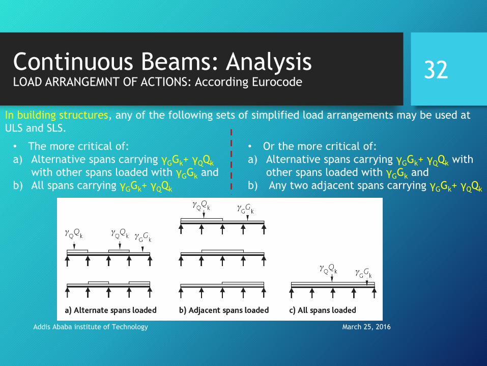
Continuous Beams: AnalysisLOAD ARRANGEMNT OF ACTIONS: According Eurocode
March 25, 2016Addis Ababa institute of Technology
32
In building structures, any of the following sets of simplified load arrangements may be used at
ULS and SLS.
• The more critical of:
a) Alternative spans carrying γGGk+ γQQk
with other spans loaded with γGGk and
b) All spans carrying γGGk+ γQQk
• Or the more critical of:
a) Alternative spans carrying γGGk+ γQQk with
other spans loaded with γGGk and
b) Any two adjacent spans carrying γGGk+ γQQk
March 25, 2016Addis Ababa institute of Technology
33
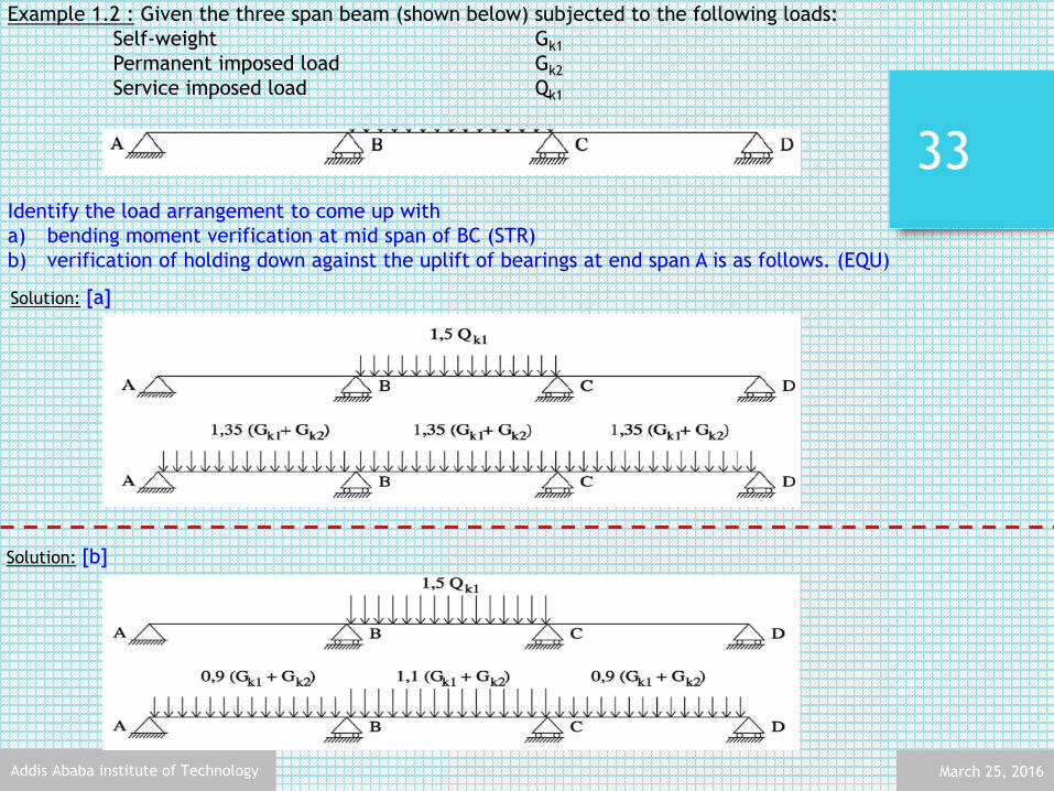
Example 1.2 : Given the three span beam (shown below) subjected to the following loads:
Self-weight Gk1
Permanent imposed load Gk2
Service imposed load Qk1
Identify the load arrangement to come up with
a) bending moment verification at mid span of BC (STR)
b) verification of holding down against the uplift of bearings at end span A is as follows. (EQU)
Solution: [a]
Solution: [b]

Continuous Beams: Design
March 25, 2016Addis Ababa institute of Technology
34
After obtaining the maximum load effects of continuous beams, the design of
continuous beam sections is carried out in the same procedure as discussed in
reinforced concrete structures I course for no moment redistribution.
SIMPLE!
For cases with moment
redistribution, the procedures
will be presented and
illustrated in the subsequent
sections

March 25, 2016Addis Ababa institute of Technology
35
Example 1.3 : A continues beam with b/h 250/450 is to be constructed out of C20/25 concrete and reinforced
with S400 reinforcement bar . The beam supports a factored permanenet load of 14.5 KN/m including its own
self-weight and a factored variable load of 29 KN/m. Take cover to stirrup to be 25 mm.
Design the beam
a) Without moment redistribution
b) With 20% moment redistribution
USE φ8 and φ20 bars as web and longitudinal reinforcement
Solution:
Step1: Summarize the given parameters
Material C20/25 fck=20MPa; fcd=11.33MPa;
fctm=2.2MPa;
Em=30,000MPa
S-400 fyk=400MPa;
fyd=347.83MPa;
Es=200,000MPa; εy=1.74‰
Geometry d=h-cover- (φstiruup +φlongitiudinal/2)
=450-25-(8+10)=407mm
Load 1.35Gk=14.5 kN/m
1.50Qk=29.0 kN/m
Step2: Identify the cases for maximum action effect on
(span and support moments)
Case1: when the whole section is loaded
Case2: alternate span loading (max. span moment at AB and CD)
Case3: alternate span loading (max. span moment at BC)

March 25, 2016Addis Ababa institute of Technology
36
Case4: two adjacent spans loading (max. support moment at B or C)
Moment envelop: (superimposing the above four cases for the
respective maximum moment)
Step3: Design the beam section according to the procedures
discussed in RC1 using the either the design chart or design table
a) Support B and C (-ve moment)
Msd=172.99 kNm
µ𝑠𝑑 =𝑀𝑠𝑑
𝑓𝑐𝑑𝑏𝑑2=
172.99 ∗ 106
11.33 ∗ 250 ∗ 4072= 0.369 > µ𝑠𝑑,𝑙𝑖𝑚
= 0.295 𝑫𝒐𝒖𝒃𝒍𝒆 𝒓𝒆𝒊𝒏𝒇𝒐𝒓𝒄𝒆𝒅
𝐾𝑧 ,𝑙𝑖𝑚 = 0.814
𝑀𝑠𝑑 ,𝑙𝑖𝑚 = µ𝑠𝑑 ,𝑙𝑖𝑚 𝑓𝑐𝑑𝑏𝑑2 = 0.295 ∗ 11.33 ∗ 250 ∗ 4072 = 138.414 𝐾𝑁𝑚
𝑍 = 𝐾𝑧 ,𝑙𝑖𝑚 ∗ 𝑑 = 0.814 ∗ 407 = 331.298 𝑚𝑚
𝐴𝑠1 =𝑀𝑠𝑑 ,𝑙𝑖𝑚
𝑍𝑓𝑦𝑑+
𝑀𝑠𝑑 ,𝑠 − 𝑀𝑠𝑑 ,𝑙𝑖𝑚
𝑓𝑦𝑑 (𝑑 − 𝑑2)=
138.414 ∗ 106
347.8 ∗ 331.298+
172.99 − 138.414 ∗ 106
347.8 ∗ (407 − 43)
= 1474.28 𝑚𝑚2
𝒖𝒔𝒆 𝟓⌀𝟐𝟎
Check the number of bars that can be placed on the single row.
Setting one 45 mm gap to insert a vibrator and making the other gaps equal to 25 mm
20𝑛 + 45 + 25 𝑛 − 2 = 250 − 2 ∗ 25 − 2 ∗ 8
20𝑛 + 45 + 25𝑛 − 50 = 184
𝑛 = 4.2
A maximum of 4 bars can be supported. Therefore, arrange the bars in to 2 rows.
Check the number of bars that can be placed on the single
row.
Setting on 45 mm gap to insert a vibrator and making the
other gaps equal to 25 mm
Revise d

March 25, 2016Addis Ababa institute of Technology
37
Revise the effective depth for the reinforcement arrangement
Compression reinforcement design
Check if the reinforcement has yielded
Calculate the stress in the concrete at the level of
compression reinforcement to avoid double counting
of area.
𝑠𝑜 𝑑 = 450 − 61 = 389 𝑚𝑚
µ𝑠𝑑 =𝑀𝑠𝑑
𝑓𝑐𝑑𝑏𝑑2
=172.99 ∗ 106
11.33 ∗ 250 ∗ 3892= 0.403 > µ𝑠𝑑 ,𝑙𝑖𝑚 = 0.295 𝑫𝒐𝒖𝒃𝒍𝒆 𝒓𝒆𝒊𝒏𝒇𝒐𝒓𝒄𝒆𝒅
𝐾𝑧 ,𝑙𝑖𝑚 = 0.814
𝑀𝑠𝑑 ,𝑙𝑖𝑚 = µ𝑠𝑑 ,𝑙𝑖𝑚 𝑓𝑐𝑑𝑏𝑑2 = 0.295 ∗ 11.33 ∗ 250 ∗ 3892 = 126.48 𝐾𝑁𝑚
𝑍 = 𝐾𝑧 ,𝑙𝑖𝑚 ∗ 𝑑 = 0.814 ∗ 389 = 316.646 𝑚𝑚
𝐴𝑠1 =𝑀𝑠𝑑 ,𝑙𝑖𝑚
𝑍𝑓𝑦𝑑+
𝑀𝑠𝑑 ,𝑠 − 𝑀𝑠𝑑 ,𝑙𝑖𝑚
𝑓𝑦𝑑 (𝑑 − 𝑑2)=
126.48 ∗ 106
347.8 ∗ 316.646+
172.99 − 126.442 ∗ 106
347.8 ∗ (389 − 43)= 1534.84 𝑚𝑚2
𝒖𝒔𝒆 𝟓⌀𝟐𝟎
𝑑2
𝑑=
43
389= 0.1 𝜀𝑠2 = 2.6‰ (𝑟𝑒𝑎𝑑 𝑓𝑟𝑜𝑚 𝑐ℎ𝑎𝑟𝑡)
𝜀𝑠2 = 2.6‰ > 𝜀𝑦𝑑 𝑢𝑠𝑒 𝑓𝑦𝑑 = 347.826
𝜀𝑐𝑠2 = 2.6‰ ≥ 2‰ , Therefore, we take
𝜀𝑐 = 3.5‰ 𝑎𝑛𝑑 𝜎𝑐𝑑 ,𝑠2 = 11.33 𝑚𝑝𝑎
𝐴𝑠2=
1(𝜎𝑠2−𝜎𝑐𝑑 ,𝑠2)
(𝑀𝑠𝑑𝑠−𝑀𝑠𝑑 ,𝑙𝑖𝑚
𝑑−𝑑2)
=1
347.826 − 11.33 ( 172.99 − 138.44 ∗ 106
389 − 43 = 399.48 𝑚𝑚2
𝒖𝒔𝒆 𝟐⌀𝟐𝟎
March 25, 2016Addis Ababa institute of Technology
38
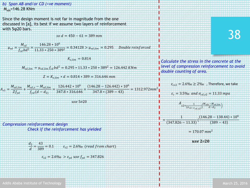
b) Span AB and/or CD (+ve moment)
Msds=146.28 KNm
Since the design moment is not far in magnitude from the one
discussed in [a], its best if we assume two layers of reinforcement
with 5φ20 bars.
Compression reinforcement design
Check if the reinforcement has yielded
𝑠𝑜 𝑑 = 450 − 61 = 389 𝑚𝑚
µ𝑠𝑑 =𝑀𝑠𝑑
𝑓𝑐𝑑𝑏𝑑2
=146.28 ∗ 106
11.33 ∗ 250 ∗ 3892= 0.34128 > µ𝑠𝑑 ,𝑙𝑖𝑚 = 0.295 𝐷𝑜𝑢𝑏𝑙𝑒 𝑟𝑒𝑖𝑛𝑓𝑜𝑟𝑐𝑒𝑑
𝐾𝑧 ,𝑙𝑖𝑚 = 0.814
𝑀𝑠𝑑 ,𝑙𝑖𝑚 = µ𝑠𝑑 ,𝑙𝑖𝑚 𝑓𝑐𝑑𝑏𝑑2 = 0.295 ∗ 11.33 ∗ 250 ∗ 3892 = 126.442 𝐾𝑁𝑚
𝑍 = 𝐾𝑧 ,𝑙𝑖𝑚 ∗ 𝑑 = 0.814 ∗ 389 = 316.646 𝑚𝑚
𝐴𝑠1 =𝑀𝑠𝑑 ,𝑙𝑖𝑚
𝑍𝑓𝑦𝑑+
𝑀𝑠𝑑 ,𝑠 − 𝑀𝑠𝑑 ,𝑙𝑖𝑚
𝑓𝑦𝑑(𝑑 − 𝑑2)=
126.442 ∗ 106
347.8 ∗ 316.646+
146.28 − 126.442 ∗ 106
347.8 ∗ (389 − 43)= 1312.972𝑚𝑚2
𝑢𝑠𝑒 5⌀20
𝑑2
𝑑=
43
389= 0.1 𝜀𝑠2 = 2.6‰ (𝑟𝑒𝑎𝑑 𝑓𝑟𝑜𝑚 𝑐ℎ𝑎𝑟𝑡)
𝜀𝑠2 = 2.6‰ > 𝜀𝑦𝑑 𝑢𝑠𝑒 𝑓𝑦𝑑 = 347.826
Calculate the stress in the concrete at the
level of compression reinforcement to avoid
double counting of area.
𝜀𝑐𝑠2 = 2.6‰ ≥ 2‰ , Therefore, we take
𝜀𝑐 = 3.5‰ 𝑎𝑛𝑑 𝜎𝑐𝑑 ,𝑠2 = 11.33 𝑚𝑝𝑎
𝐴𝑠2=
1(𝜎𝑠2−𝜎𝑐𝑑 ,𝑠2)
𝑀𝑠𝑑𝑠−𝑀𝑠𝑑 ,𝑙𝑖𝑚
𝑑−𝑑2
=1
347.826 − 11.33 ( 146.28 − 138.44 ∗ 106
389 − 43
= 170.07 𝑚𝑚2
𝒖𝒔𝒆 𝟐⌀𝟐𝟎

March 25, 2016Addis Ababa institute of Technology
39
c) Span BC (+ ve moment)
Span BC is selected of all the three positive bending moments as its
higher in values.
𝑀𝑠𝑑=91.66 KN m
𝜇𝑠𝑑, 𝑠 =𝑀𝑠𝑑,𝑠
𝑓𝑐𝑑∗𝑏∗𝑑2 = 91.66∗106
11.33∗250∗4072
= 0.195 < 𝜇𝑠𝑑, 𝑙𝑖𝑚 = 0.295
Singly reinforced section
Kz = 0.89 read from chart
𝐴𝑠1 =1
𝑓𝑦𝑑∗𝑀𝑠𝑑, 𝑠
𝑧
𝐴𝑠1 =1
347.8∗91.66 ∗ 106
0.89 ∗ 407
𝐴𝑠1 = 727.5 𝑚𝑚2
Use 3φ20
d) Span BC (- ve moment)
Msd=38.84 kNm
Use 2 φ 20, minimum reinforcements is proved to be sufficient.
Step4: Detailing
Plastic Hinges and Collapse Mechanisms
March 25, 2016Addis Ababa institute of Technology
40
Plastic Hinges and Collapse Mechanisms
March 25, 2016Addis Ababa institute of Technology
41
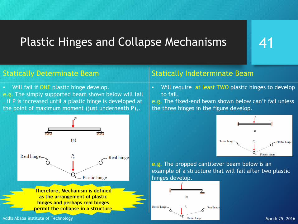
Statically Determinate Beam Statically Indeterminate Beam
• Will fail if ONE plastic hinge develop.
e.g. The simply supported beam shown below will fail
, if P is increased until a plastic hinge is developed at
the point of maximum moment (just underneath P),.
• Will require at least TWO plastic hinges to develop
to fail.
e.g. The fixed-end beam shown below can’t fail unless
the three hinges in the figure develop.
e.g. The propped cantilever beam below is an
example of a structure that will fail after two plastic
hinges develop.
Therefore, Mechanism is defined
as the arrangement of plastic
hinges and perhaps real hinges
permit the collapse in a structure

Plastic Hinges and Collapse Mechanisms
March 25, 2016Addis Ababa institute of Technology
42
• If the structure is statically indeterminate, it is still stable after the formation of a
plastic hinge, and for further loading, it behaves as a modified structure with a hinge
at the plastic hinge location (and one less degree of indeterminacy).
• It can continue to carry additional loading (with formation of additional plastic
hinges) until the limit state of collapse is reached on account of one of the following
reasons:
1. formation of sufficient number of plastic hinges, to convert the structure (or a
part of it) into a ‘mechanism’.2. limitation in ductile behavior (i.e., curvature ϕ reaching the ultimate value
ϕmax, or, in other words a plastic hinge reaching its ultimate rotation capacity)
at any one plastic hinge location, resulting in local crushing of concrete at that
section.
From the discussion in the previous slide we can point out the following as an observation
March 25, 2016Addis Ababa institute of Technology
43
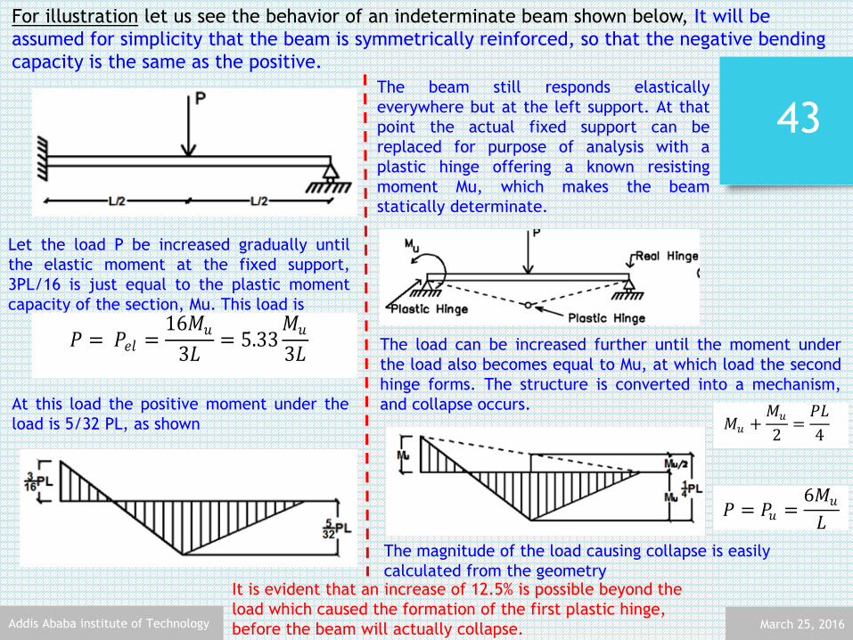
For illustration let us see the behavior of an indeterminate beam shown below, It will be
assumed for simplicity that the beam is symmetrically reinforced, so that the negative bending
capacity is the same as the positive.
Let the load P be increased gradually until
the elastic moment at the fixed support,
3PL/16 is just equal to the plastic moment
capacity of the section, Mu. This load is
𝑃 = 𝑃𝑒𝑙 =16𝑀𝑢
3𝐿= 5.33
𝑀𝑢
3𝐿 (1.1)
At this load the positive moment under the
load is 5/32 PL, as shown
The beam still responds elastically
everywhere but at the left support. At that
point the actual fixed support can be
replaced for purpose of analysis with a
plastic hinge offering a known resisting
moment Mu, which makes the beam
statically determinate.
The load can be increased further until the moment under
the load also becomes equal to Mu, at which load the second
hinge forms. The structure is converted into a mechanism,
and collapse occurs.
The magnitude of the load causing collapse is easily
calculated from the geometry
𝑀𝑢 +𝑀𝑢
2=
𝑃𝐿
4
𝑃 = 𝑃𝑢 =6𝑀𝑢
𝐿
It is evident that an increase of 12.5% is possible beyond the
load which caused the formation of the first plastic hinge,
before the beam will actually collapse.
March 25, 2016Addis Ababa institute of Technology
44
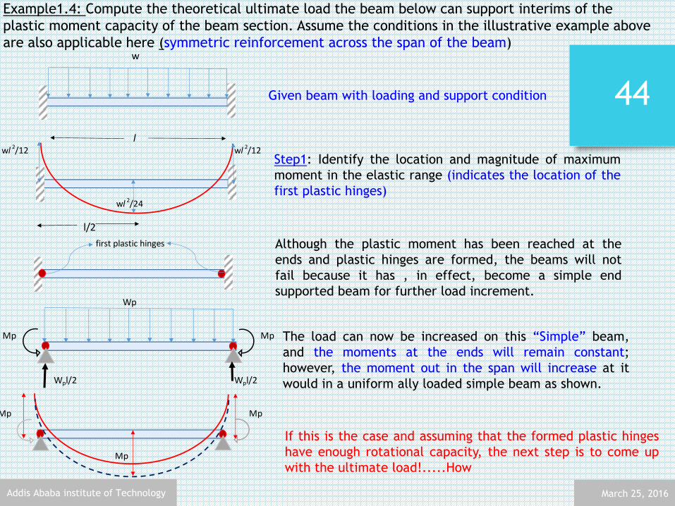
Example1.4: Compute the theoretical ultimate load the beam below can support interims of the
plastic moment capacity of the beam section. Assume the conditions in the illustrative example above
are also applicable here (symmetric reinforcement across the span of the beam)
Given beam with loading and support condition
Step1: Identify the location and magnitude of maximum
moment in the elastic range (indicates the location of the
first plastic hinges)
If this is the case and assuming that the formed plastic hinges
have enough rotational capacity, the next step is to come up
with the ultimate load!.....How
w
l
wl 2/24
l/2
wl 2/12 wl 2/12
first plastic hinges Although the plastic moment has been reached at the
ends and plastic hinges are formed, the beams will not
fail because it has , in effect, become a simple end
supported beam for further load increment.Wp
Mp Mp
Wpl/2 Wpl/2
The load can now be increased on this “Simple” beam,
and the moments at the ends will remain constant;
however, the moment out in the span will increase at it
would in a uniform ally loaded simple beam as shown.
Mp Mp
Mp
March 25, 2016Addis Ababa institute of Technology
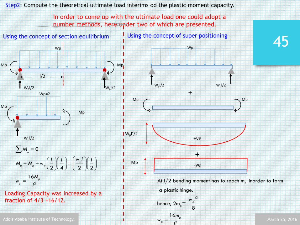
45
In order to come up with the ultimate load one could adopt a
number methods, here under two of which are presented.
Using the concept of section equilibrium Using the concept of super positioning
Step2: Compute the theoretical ultimate load interims od the plastic moment capacity.
Wp
Mp
Wpl/2 Wpl/2
Mp Mp
+
Wpl2/2
Mp
+
+ve
-ve
p
2
p
2
At l/2 bending moment has to reach m inorder to form
a plastic hinge.
hence, 2m = 8
16
p
p
p
w l
mw
l
Wp
Mp Mp
l/2
Wpl/2 Wpl/2
Wp=?
Mp
Mp
Wpl/2
2
0
2 4 2 2
16
o
p
p p p
p
p
M
w ll l lM M w
Mw
l
Loading Capacity was increased by a
fraction of 4/3 =16/12.

Moment Redistribution
March 25, 2016Addis Ababa institute of Technology
46

Moment Redistribution
March 25, 2016Addis Ababa institute of Technology
47
As seen in the previous section, the distribution of bending moments in a continuous
beam (or frame) gets modified significantly in the inelastic phase.
The term moment redistribution is generally used to refer to the transfer of moments to the
less stressed sections as sections of peak moments yield on their ultimate capacity being
reached (as witnessed in the example above).
From a design viewpoint, this behavior can be taken advantage of by attempting to effect a
redistributed bending moment diagram which achieves a reduction in the maximum moment
levels (and a corresponding increase in the lower moments at other locations).
Such an adjustment in the moment diagram often leads to the design of a more economical
structure with better balanced proportions, and less congestion of reinforcement at the
critical sections.
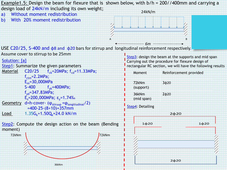
Example1.5: Design the beam for flexure that is shown below, with b/h = 200//400mm and carrying a
design load of 24kN/m including its own weight;
a) Without moment redistribution
b) With 20% moment redistribution
USE C20/25, S-400 and φ8 and φ20 bars for stirrup and longitudinal reinforcement respectively.Assume cover to stirrup to be 25mm
Solution: [a]
Step1: Summarize the given parameters
Material C20/25 fck=20MPa; fcd=11.33MPa;
fctm=2.2MPa;
Em=30,000MPa
S-400 fyk=400MPa;
fyd=347.83MPa;
Es=200,000MPa; εy=1.74‰
Geometry d=h-cover- (φstiruup +φlongitiudinal/2)
=400-25-(8+10)=357mm
Load 1.35Gk+1.50Qk=24.0 kN/m
Step2: Compute the design action on the beam (Bending
moment)
24kN/m
A B
6m
36kNm
72kNm 72kNm
Step3: design the beam at the supports and mid span
Carrying out the procedure for flexure design of
rectangular RC section, we will have the following results
Moment Reinforcement provided
72kNm
(support)
3φ20
36kNm
(mid span)
2φ20
Step4: Detailing
2φ20
1φ20 1φ20
2φ20

Solution: [b]
Step1: Summarize the given parameters
Material C20/25 fck=20MPa; fcd=11.33MPa;
fctm=2.2MPa;
Em=30,000MPa
S-400 fyk=400MPa;
fyd=347.83MPa;
Es=200,000MPa; εy=1.74‰
Geometry d=h-cover- (φstiruup +φlongitiudinal/2)
=400-25-(8+10)=357mm
Load 1.35Gk+1.50Qk=24.0 kN/m
Moment redistribution up 20% is allowed.
Step2: Select a critical section and carryout the moment
redistribution
Step3: design the beam at the supports and mid span
Carrying out the procedure for flexure design of
rectangular RC section, we will have the following
results.
But keep in mind the value μlim for 20%moment redistribution which is 0.205
Design Moment before
redistribution
Design Moments after
redistribution
72kNm (support) 57.6kNm (support)
36kNm (mid span) 50.4kNm (mid span)
Step4: Detailing
2φ20
2φ2036kNm
Mspan
57.6kNm
72kNm 72kNm
57.6kNm
0.2 72 14.4
72 14.4 57.6
kNm kNm
kNm kNm kNm
2
0
2472 57.6
2 2
50.4
o
span
span
M
l lM
M kNm
24kN/m
57.6kNm
Mspan
72kN
Moment Reinforcement provided
57.6kNm (support) 2φ20
50.4kNm (mid span) 2φ20

March 25, 2016Addis Ababa institute of Technology
50

Thank you for the kind attention!
Questions?
March 25, 2016Addis Ababa institute of Technology
51