chapter one: control network fundamentaliveeng.tripod.com/cn0100.pdf · communication between nodes...
TRANSCRIPT

Chapter One: Control Network Fundamental
1. Control Network Architecture
Introduction Networks are changing our lives. Everywhere we turn, they are used to collect and move data, connected to computers and run business.
In the past, network performed these functions locally. Today, the Internet allows that networks operate globally.
Now, another networking revolution will have an even greater impact than Internet: Control network is extending the concept of networking into the world of control. Control networks greatly expand the possibility of networking. When combined with data networks, control networks provide immediate and vital information on the enterprise, along with the means to act on it instantly. Control networks link devices-replacing the central controllers and wiring harnesses of yesterday.
Although open systems are commonplace in data networks, control systems have traditionally been closed and proprietary architectures.
What is Control Network?
A control network is a network of nodes that collectively monitor, sense, and control or enable control of a process or an environment. A home appliance network is a good example of a control network. In fact, thousands of control networks already exist in everyday life in automobiles, refrigerators, traffic light controls, city lighting systems, and on factory floors. Control networks vary enormously in the number of nodes (from three to thousands) in the network and in their complexity. Unlike networks that people use to communicate with each other, control networks tend to be invisible. In the future, control networks are expected to become an important aspect of what is sometimes called ubiquitous computing.
Communication between nodes in a control network may be peer-to-peer or master-slave. The nodes in some control networks contain three processors in one: two dedicated to moving data within the network and one for the specialized program associated with that node. This modularity makes it cheaper and faster to build new processors for control networks. Increasingly, control networks are being made from off-the-shelf hardware and software components.
One future role for control networks will be as the controllers of microelectromechanical sytems (MEMS), sometimes referred to as smart matter. Because it greatly expands the number of items in the world that can be uniquely addressed in a network, IPv6, a new version of the Internet Protocol (IP), is expected to make remote access and control of all kinds of devices

possible, including every networked appliance at your office or at home. Sun Microsystem's Jini, will make it easy to plug new devices into a control network and have their characteristics immediately recognized by the system.
A generic control network architecture according to functionality based on TC247/WG 4 is shown on the following diagram:
Fig. 1.1
Working Group 4 divided the communications within a control network management system into three types of communications requirement: the ‘Management’ net (workstation to workstation communication) , the ‘Automation’ or ‘Control’ net (plant controllers and workstations) and the ‘Field’ net (terminal unit controls and communicating sensor devices etc.). This is because they felt these levels need to support different quantities of devices, have different amounts of information to be sent, require different communication performance, and support different types of transport media (the physical cable etc.).

The bus interface between different levels may take the form of direct connection, router or gateway. TC247 has selected several provisional norms on each level as shown below :-
Level CEN Standard Date Protocol Transmission Media
Management ENV 1805-1 1996 FND X25 to network access unit
ENV 1805-2 1998 BACnet Ethernet - all media types
PSTN / Dial up modem
Automation ENV 13321-1 1999 PROFIBUS PROFIBUS FMS - twisted pair
WorldFIP Twisted pair
BACnet Ethernet - all media types
LONtalk - all media types
PSTN / Dial up modem
ENV13321-2 2000? EIB Ethernet - all media types
Field ENV13154-2 1998 EIB Twisted pair, Mains signalling
EHS Twisted pair, Coax, Radio etc
BATIBUS Twisted pair
LONtalk Twisted pair, Mains signalling, radio etc
Thus it is possible select mutually incompatible protocols for the different levels which require gateways to link different levels. At the field level an alliance for convergence was announced in March 1996 between EIB, BATIBUS and EHS. This alliance has an agreement to develop a new unified protocol which will be built on the best features of the existing standards. It will be compatible with EIB and will include some of the "plug and play" functions of EHS. TC247 Task Group 3-4 has defined a set of "objects" which are intended to facilitate the operation between the different field level protocols and BACnet.
There are many ways to create automation systems, from pneumatics to custom, proprietary hardware and software solutions, to open interoperable, standards-based control networks. Today’s automation market clearly calls for the latter.

These open device networks have common character including an open protocol; flat peer-to-peer architectures; device level interoperability; and a network operating system for easy network management, installation, troubleshoot and remote services. Automation networks have evolved similarly to PC networks. Figure 1.2 illustrates how we have progressed from centralized single master-many slave systems, e.g., mainframe and terminals; to multi-master/multi-slave (one form of modified model as shown in Fig.1.1), e.g., mini; to flat architectures, e.g. PC-based networks.
Fig. 1.2 Typical Device Network Architectures
For automated controls, flat and peer-to-peer (P2P) architectures are best. P2P architectures lack single points of failures inherent in any hierarchical architecture, in which, messages from one device must go first to a controlling master or gateway BEFORE the signal can get to the target device. Therefore, every communication between two non-master devices includes an extra step, or fault possibility. P2P designs, by contrast, allow direct communication between two devices eliminating the fault possibility of the master controller and removing a potential performance bottleneck. Further, device failures in a P2P design are much more likely to affect just the one device, not the potentially many as one finds in non-flat, not peer-to-peer architectures.
In summary, networks built with flat open network character can deliver lower cost at integration and commissioning, have significantly lower life-cycle costs, allow for easier changes and enhancements, are more flexible, and finally are more adaptable to the end users.
One example of an open, device networking communications protocol enable the flat open approach is EIA/ANSI 709.1 (the LonWorks Platform). Thousands of companies today support the use of this protocol. Chip suppliers Toshiba and Cypress Semiconductor have competing families of microprocessors optimized for executing the protocol in cost imperative or performance imperative applications.
Control Network Operating Systems Just like data network, every control network has one or more operating system. At the installation stage, NOS allows an installer to work on each sub-system sequentially, or
multiple sub-system installers to work simultaneously, for instance, a lighting system could be commissioned at the same time as an HVAC system. An NOS also gives manufacturers a software architecture for creating simple plug-ins that allow integrators to easily see and configure various aspects of a device or system such as temperature set points or schedules.
After commissioning has been completed and the facility is operational, NOS plays a vital role in providing network information including device health, operating characteristics, maintenance information and energy demand. The data is available for presentation through a variety of Human/Machine Interfaces (HMI) that can disseminate this information through client-server based architectures (e.g., National Instruments LabVIEW, Wonderware’s Intouch). The pervasiveness of the Internet now enables this information to be shared through any web aware client, driving down costs and greatly increasing value. Time critical actions can now be affected as the NOS allows remote access to the automation network to such an extent as to allow facility managers or integrators to perform the exact same tasks that they could if they were locally plugged into the network.
Device Level Interoperability Any discussion of interoperability should begin with a definition of what it means. Simply, interoperability in an automation network is defined as the ability of devices from one manufacturer to understand and use data from another manufacturer’s device regardless of sub-system types or original purpose without the intervention of very costly gateways or protocol converters.
The benefits made possible by interoperability are many. Automation systems get simple (re: more reliable) since one sensor or device can be shared among many different sub-systems. They also get cheaper as fewer sensors/controllers are needed in the system and costs drop appreciably as parts are reduced and installation time and complexity decrease. Lastly, more can be done with an automation network when the devices are interoperable. For example, in response to access control reader data and daylight illumination sensors, the HVAC and lighting systems can automatically adjust the comfort and illumination levels in pertinent work areas based on individual preferences and energy costs. Lighting can be adjusted on a cubicle-by-cubicle basis for computer operators and occupants near windows- either automatically or through commands entered from a user’s PC via the corporate LAN. Heating and air conditioning can by similarly tailored.
Delivering Tangible Benefit from Open Interoperable Device Networks
Automation networks for commercial or residential applications merely begin with open interoperable device networks. The next thing that is necessary is what known as an open system. Open systems are created using products from multiple vendors that conform to uniform industry standards, enabling full interoperability across a unified network. They are

supported by unaffiliated manufacturers, integrators, distributors and technology providers and are based on open networking and automation standards. Figure 1.3 below illustrates the ecosystem for delivering open systems in reference to ANSI/EIA 709.1 Control Network standard.
Fig. 1.3 Using ANSI/EIA 709.1 Control Network standard to illustrate an Open Systems Ecosystem (courtesy of
Echelon Corporation)
The benefits of a truly open system include:
• The ability for owners and integrators to choose amongst best-of-breed, off-the-shelf components selected from among different manufacturers for both initial installations and enhancements down the road that are not tied to one manufacturer’s closed technology
• Lower system costs since the ability to choose fosters greater price competition • Less complexity and fewer failure points through the elimination of gateways to bridge
between sub-systems • Lower cost deployments because it’s faster to deploy interoperable products than
non-interoperable products • The modularity of open systems enables changes and expansion to occur in a less-costly
and less-complex manner • Lower life-cycle costs, particularly from an operations and maintenance perspective
Open systems are really about a platform choice – one that supports all the sub-systems in a facility including lighting, HVAC, access, security, elevator, blinds, emergency systems, environment monitoring, water supply, energy and others. Like any network, as an open system increases the number of devices, the power of the network, and therefore the benefits derived by the end-user, increase dramatically.

Leveraging Open Systems & Internet for Advanced Facility Management
As more and more people, devices, computers, businesses, factories, services, and utilities join the rush to the Internet, the value of connecting it all grows exponentially. This is as true for light switches, machine tools, heating and air conditioning systems as it is for computers and browser-based appliances.
The age of Internet created a phenomenon in which people rush to put IP (Internet Protocol) everywhere from toasters to light switches to motion sensors. Such an architecture, from an automation perspective, suffers from a lot of shortcomings. If you add to those inherent shortcomings the cost and complexity of IP networking, one quickly realizes that embedding IP into every device in an automation network is not a suitable automation solution.
There is a better way. The chaos of the Internet, ironically, brings order—and opportunity—to those involved in servicing and managing broadband enabled properties. The Internet provides low-cost, ubiquitous remote connectivity and a standard platform for communications between humans and electronic devices.
The more effective way to integrate the Internet into an automation network is have the NOS speak IP. Doing so allows the automation network to be optimized for local control, monitoring, and sensing while at the same time allowing remote (or local) IP clients such as web browsers or WAP phones, to interact with individual devices on the automation network as if each one had an IP stack embedded inside. Such an architecture allows property and facility management companies to interact remotely with a customer’s building in real time, from anywhere in the world.
Remote Control and Efficiency A single, open automation network connected to the Internet can give property and facility managers a real-time, detailed view of every system throughout the building or campus—from HVAC and lighting to security and landscaping irrigation—24 hours a day. Alarms indicating fluctuations in equipment performance enable managers to often anticipate problems before the system fails. Scheduled repairs replace costly breakdowns and systems are maintained with minimal disruption to tenants. Many problems can be corrected on line, such as adjustments to air handlers, lighting, and heating or cooling. Improved preventive maintenance leads to longer equipment life, again reducing costs.
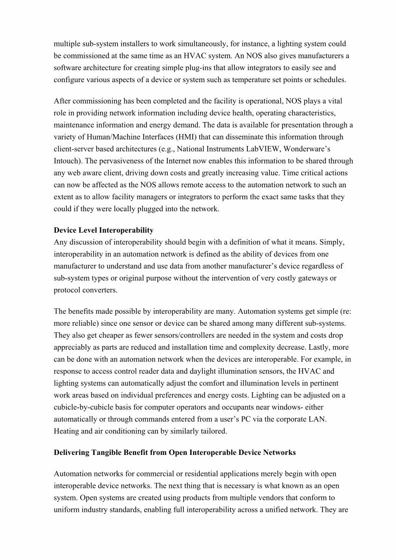
Figure 1.4 below illustrates the basic architecture used to leverage automation networks from multiple properties regardless of regional distribution. As discussed above, each property has its own dedicated automation network with local control, monitoring and sensing capabilities. The IP network (Internet) is used as the backbone to aggregate information up to business
systems (e.g., service scheduling, warranty tracking, customer resource management, et. al.) and as the path for remote network administration.
Fig. 1.4 Wide Area Service Architecture
This immediate, remote access to information provided open systems based on open interoperable device networks allows facility managers to be far more efficient. Information enables improved decisions regarding the need to “roll a truck” at the start of a normal business day rather than at 2:00 AM. The ability to make these types of decisions results in reduced cost of operations. One facility manager can now effectively and efficiently handle buildings and facilities that previously required individual monitoring and management. Savvy companies can set up a portfolio of multiple sites with millions of square feet—across the US or around the world. This reduces labor costs and increases profits to the management company, lowers ongoing operating expenses for building owners, and provides much higher levels of customer support to building occupants.
There are many ways to build automation systems for buildings and residential applications. Automation systems that leverage technical advancements based on open standards deliver on all the benefits and promise of open systems to building owners, integrators, and manufacturers. Clearly some ways are better than others.
The OSI 7-layers protocol
OSI (Open Systems Interconnection) is a standard description or "reference model" for how messages should be transmitted between any two points in a network, be it a data network or control network. Its purpose is to guide product implementers so that their products will consistently work with other products. The reference model defines seven layers of functions that take place at each end of a communication. Although OSI is not always strictly adhered to

in terms of keeping related functions together in a well-defined layer, many if not most products involved in telecommunication make an attempt to describe themselves in relation to the OSI model. It is also valuable as a single reference view of communication that furnishes everyone a common ground for education and discussion.
Developed by representatives of major computer and telecommunication companies beginning in 1983, OSI was originally intended to be a detailed specification of interfaces. Instead, the committee decided to establish a common reference model for which others could develop detailed interfaces, that in turn could become standards. OSI was officially adopted as an international standard by the International Organization of Standards (ISO). Currently, it is Recommendation X.200 of the ITU-TS.
The main idea in OSI is that the process of communication between two end points in a telecommunication network can be divided into layers, with each layer adding its own set of special, related functions. Each communicating user or program is at a computer equipped with these seven layers of function. So, in a given message between users, there will be a flow of data through each layer at one end down through the layers in that computer and, at the other end, when the message arrives, another flow of data up through the layers in the receiving computer and ultimately to the end user or program. The actual programming and hardware that furnishes these seven layers of function is usually a combination of the computer operating system, applications (such as your Web browser), TCP/IP or alternative transport and network protocols, and the software and hardware that enable you to put a signal on one of the lines attached to your computer.
OSI divides telecommunication into seven layers. The layers are in two groups. The upper four layers are used whenever a message passes from or to a user. The lower three layers (up to the network layer) are used when any message passes through the host computer. Messages intended for this computer pass to the upper layers. Messages destined for some other host are not passed up to the upper layers but are forwarded to another host. The seven layers are:
Layer 7: The application layer...This is the layer at which communication partners are identified, quality of service is identified, user authentication and privacy are considered, and any constraints on data syntax are identified. (This layer is not the application itself, although some applications may perform application layer functions.)
Layer 6: The presentation layer...This is a layer, usually part of an operating system, that converts incoming and outgoing data from one presentation format to another (for example, from a text stream into a popup window with the newly arrived text). Sometimes called the syntax layer.

Layer 5: The session layer...This layer sets up, coordinates, and terminates conversations, exchanges, and dialogs between the applications at each end. It deals with session and connection coordination.
Layer 4: The transport layer...This layer manages the end-to-end control (for example, determining whether all packets have arrived) and error-checking. It ensures complete data transfer.
Layer 3: The network layer...This layer handles the routing of the data (sending it in the right direction to the right destination on outgoing transmissions and receiving incoming transmissions at the packet level). The network layer does routing and forwarding.
Layer 2: The data-link layer...This layer provides synchronization for the physical level and does bit-stuffing for strings of 1's in excess of 5. It furnishes transmission protocol knowledge and management.
Layer 1: The physical layer...This layer conveys the bit stream through the network at the electrical and mechanical level. It provides the hardware means of sending and receiving data on a carrier.
Figure 1.5 shows where commonly-used Internet products and services fit within the model. Notes: The OSI Reference Model describes seven layers of related functions that are needed at each end when a message is sent from one party to another party in a network. An existing network product or program can be described in part by where it fits into this layered structure. For example, TCP/IP is usually packaged with other Internet programs as a suite of products that support communication over the Internet. This suite includes the File Transfer Protocol (FTP), Telnet, the Hypertext Transfer Protocol (HTTP), e-mail protocols, and sometimes others. Although TCP fits well into the Transport layer of OSI and IP into the Network layer, the other programs fit rather loosely (but not neatly within a layer) into the Session, Presentation, and Application layers.
In this figure, we include only Internet-related programs in the Network and higher layers. OSI can also be applied to other network environments. A number of boxes under the Application and the Presentation layers do not fit as neatly into these layers as they are shown. A set of communication products that conformed fully to the OSI reference model would fit neatly into each layer.

Fig. 1.5 commonly-used Internet products and services map with OSI 7-layers
2. Control Network vs. Data Network
In some ways, control network resembles a computer data network referred to as a Local Area Network (LAN). Data networks consist of computers attached to various communications media, connected by routers, which communicate with one another using a common protocol such as TCP/IP. Data networks communication protocols are designed and optimized for moving large amounts of data between computers designed for batch processing, and the design of data network protocols assume that occasional delays in data delivery and response are acceptable.
Control networks contain similar pieces optimized for the cost, performance, size, and response requirements of control. Control networks have a number of unique requirements that make them different from data networks. These include (1) frequent, reliable, secure communications between devices; (2) short message formats for the information being passed; (3) peer-to-peer functionality for every devices; (4) price points that enable small, low-cost devices. Control networks also allow networked systems to extend into a class of applications that data networking technology cannot reach. Control networks range in sophistication from small networks embedded in machines to large networks with thousands of devices controlling fusion lasers, paper manufacturing machines, and
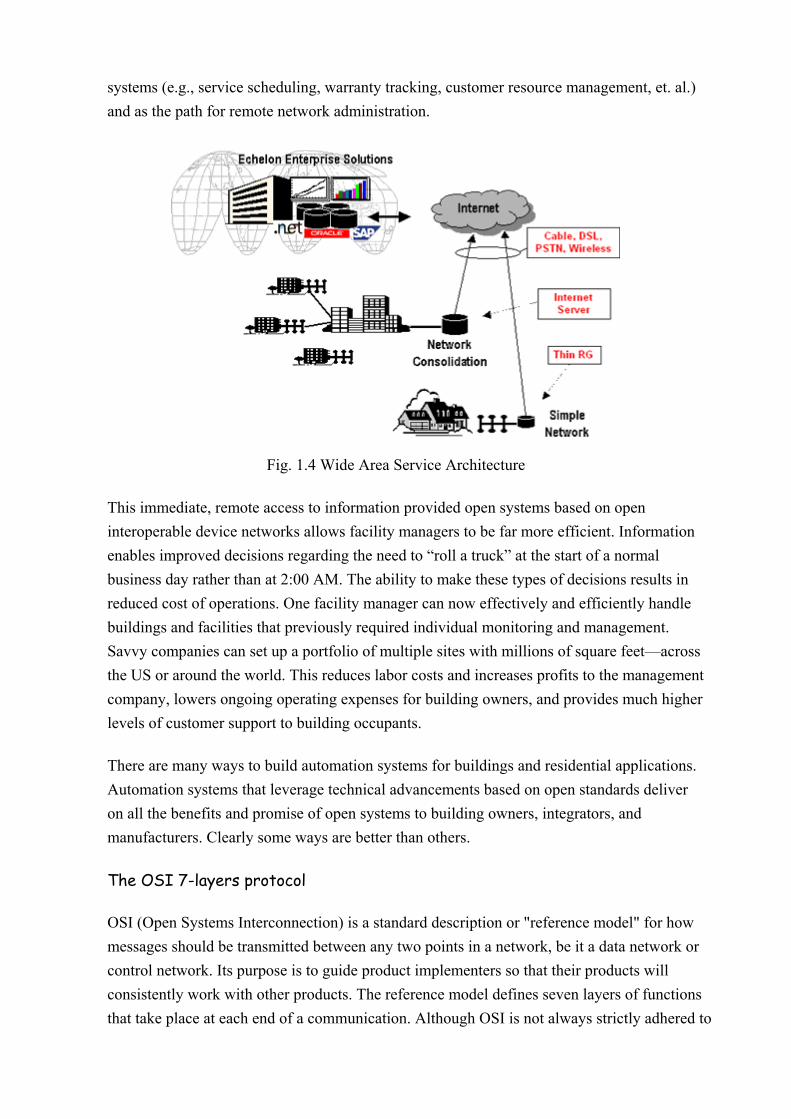
building automation systems. Control networks are used in buildings, trains, airplanes, factories, and hundreds of other processes.
Fig.2-1 Example of Telecommunications Data Network
Control systems are far more pervasive and extensive than data computers. There are many more sensors and actuators than there are personal computers. There are sensors in your car, in the plane, in the security system and much more. And even more so than computers, these sensors need to have interconnections. The control loops may be limited to the machine the size of a copier or a car, and can be extended to a large building or factory, which consists of hundreds to several thousand network nodes.

Fig2.2 Example Control Network (“Internet” cloud is wholly or part of Fig.2.1 above)
2.1 Localized control network components
Fig.2.3 illustrates the key components of a localized control network. A control network consists of intelligent devices that communicate with each other using a common protocol over one or more communications channels. Network devices are sometimes called nodes.
Each device includes one or more processors that provide its intelligent and implement the protocol. Each device also includes a component called a transceiver to provide its electrical interface to the communications channel.
A device publishes information as appropriate to the application that it is running. The applications are not synchronized, and it is possible that multiple devices may all try to talk at the same time. Meaningful transfer of information between devices on the network, therefore, requires organization in the form of a set of rules and procedures. These rules and procedures are called the communication protocol. The protocol defines the format of the message being transmitted between devices and defines the actions expected when one device sends a message to another. The protocol normally takes the form of embedded software or firmware code in each device on the network.

Fig.2.3 Localized Control Network components
The path between devices exhibits various physical characteristics and is called communications channel. Different Transceivers may be able to interoperate on the same channel, so channels are categorized by channel type, and every type of transceiver must identify the channel type or types that it supports. The choice of channel type affects transmission speed and distance as well as the network topology. Transceivers could be available for a variety of communications media including single twisted-pair cable, power line, radio frequency (RF), infrared, fibre optics, and coax cable.
3. Conventional vs. Distributed control
Control systems of the ‘90s are following the same path taken by computer systems of the ‘80s. They are moving from proprietary hardware and software operating in centralized system architectures, and towards open systems featuring distributed, networked intelligence.
At one time, control logic was derived either through electromechanical relay panels or via pneumatic receiver/controllers. The advent of solid-state technology offered a means of reducing costs and increasing flexibility by using logic circuits to replace the wire or tubing and relays. Increasingly powerful algorithms were developed allowing tighter control over processes. It was often the proprietary nature of the system’s hardware and software that caused the adds, moves, and changes difficult especially when systems grew in size.
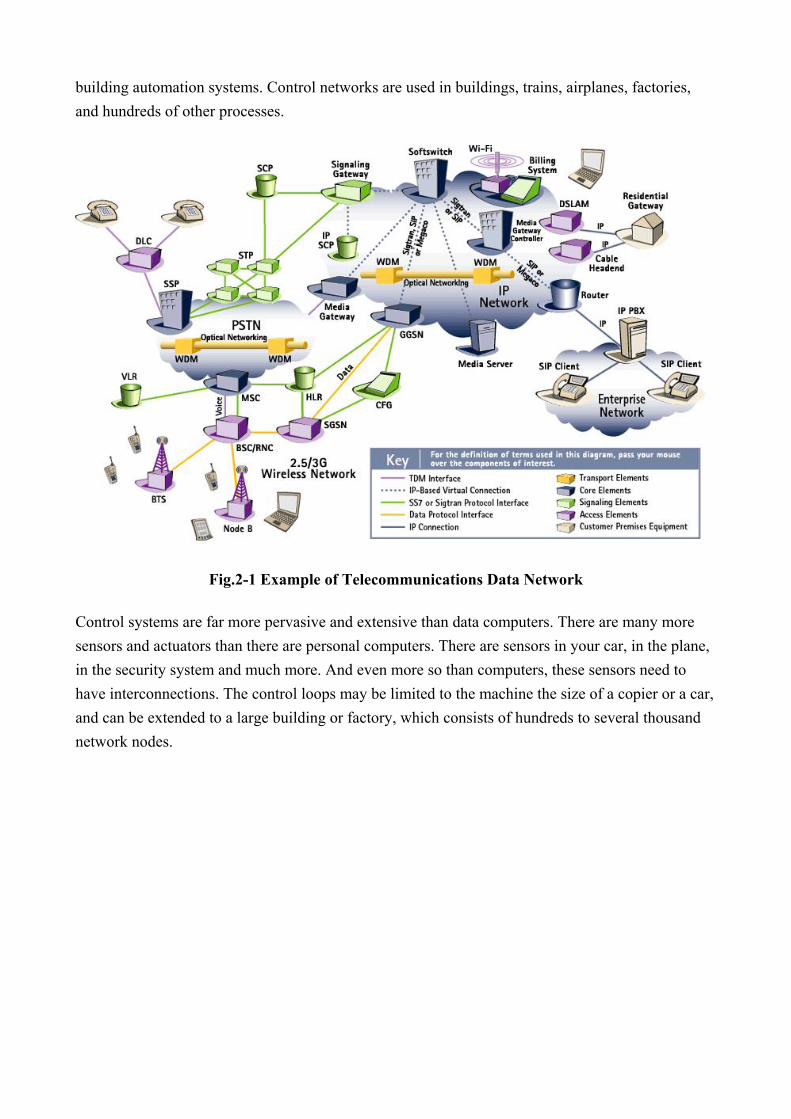
Control systems in the conventional architecture are centralized systems as shown in Fig.3.1, and up until recently has been typical of most control systems in commercial and industrial applications. Sensors and actuators are wired to a sub-panel, which in turn connects to the controller panel via a proprietary master/slave communication bus. The controller panel contains a high-performance microprocessor running a custom application program that implements the control logic for all the I/O points connected to it. For large systems, this controller may communicate over another proprietary ‘dumb’ I/O devices, meaning they have no internal intelligence or communication capabilities. The system typically has a proprietary human-machine interface (HMI). Every system must have a custom application program. This application is often developed using a proprietary programming language and non-standard software tools that are manufacture specific. Data transformation from one mode to another is often problematic, especially where compatibility was not always given. The biggest disadvantage is the complex control, which becomes even more complex as functions are assumed.
Fig.3.1 Centralized Architecture
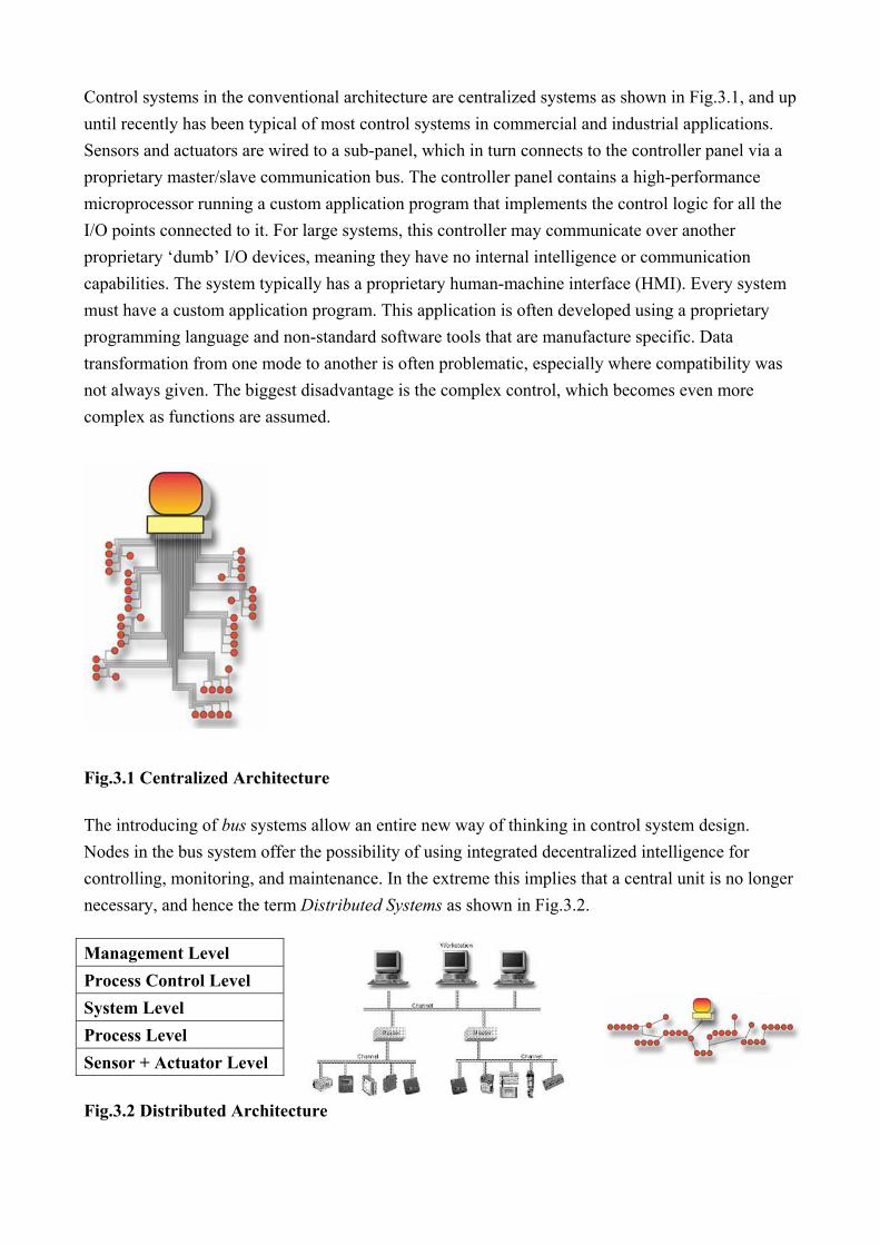
The introducing of bus systems allow an entire new way of thinking in control system design. Nodes in the bus system offer the possibility of using integrated decentralized intelligence for controlling, monitoring, and maintenance. In the extreme this implies that a central unit is no longer necessary, and hence the term Distributed Systems as shown in Fig.3.2.
Management Level Process Control Level System Level Process Level Sensor + Actuator Level
Fig.3.2 Distributed Architecture

There are five crucial features which characterize distributed systems, namely, (1) the hardware architecture; (2) the principle of data processing; (3) the location of data storage; (4) the control mechanism on the communication network; and (5) the system transparency.
Distributed systems, in general, do not share memory that could be used for inter-process communication. The only possible way for information exchange between distributed components is the exchange of message over the network. Sender and receiver behave as equal communication partners, so that an unstructured message exchange appears. This flexible but not easily controllable data flow demands efficient and adaptive communication services, which mostly are hierarchically structured within a protocol stack. This arrangement provides common software architecture when implementing distributed systems.
Nowadays, the term “distributed system” is used for a broad spectrum of multi-computer and multiprocessor systems in various applications and with different hardware architectures. We shall restrict the description to distributed system concepts to those commonly used in distributed automation systems, where sensors, actuators, and control units are interconnected, with the main goal to perform a control or measurement application and to provide a human machine interface (HMI) through exchanging data among themselves.
Following are some significant characteristics of distributed control systems:
1. Distributed control systems assume that in each distributed sensor and actuator node enough processing power is available, so that local data and signal processing can be performed locally.
2. The exchange of information in a distributed control system is given by the internetworking with a common communication system (control network).
3. The length of communication messages in most applications is only several bits or bytes. Physical signals from the sensors are processed in the local node and sent to related controllers and actuators over the control network.
4. Requirement on response times for sensor and actuator signals in the process automation are usually greater than 1 ms. In building automation response intervals are clearly longer.
The spatial distribution of system parts and the complexity of the networked systems make the continuous synchronization of data among cooperative nodes impractical, only to a few or to a confined group if necessary. Each data exchange is usually explicitly requested according to the communication process. This data exchange procedure is time consuming and in most cases time delays cannot be neglected, therefore, design of distributed control system has to be carefully planned.
On the other hand, the distributed processing power may help to obtain higher system reliability. In the case of communication breakdown, each single node in the system is still enabled to process

local data and to perform the local control function, sometimes only to continue emergency functions of the whole system.
Each single unit in the distributed control system sends its information autonomously, without possibly knowing the exact state of other parts of the system or the whole system itself. The failure or breakdown of a node can be recognized only after a time delay. Therefore, time-critical applications with safety requirements, when implemented in distributed control systems, should implement sufficient monitoring functions.
In system with centralized system control master, this unit is the most critical part of the system. It provides the communication control and contains the replication of process states in the whole system. Therefore the failure of the master unit may cause the whole system to fail. Also, the communication traffic is more intense than in systems with distributed communication control.