chapter one electrical system components 1. electrical components electrical components can be...
TRANSCRIPT
1
Chapter One
Electrical System Components
Electrical Components
• Electrical components can be divided into 7 categories based on function.
1 Source2 Transmission3 Service Entrance Panel (SEP)4 Conductors5 Connectors6 Enclosures7 Controls
2
1 & 2. Generation & Transmission
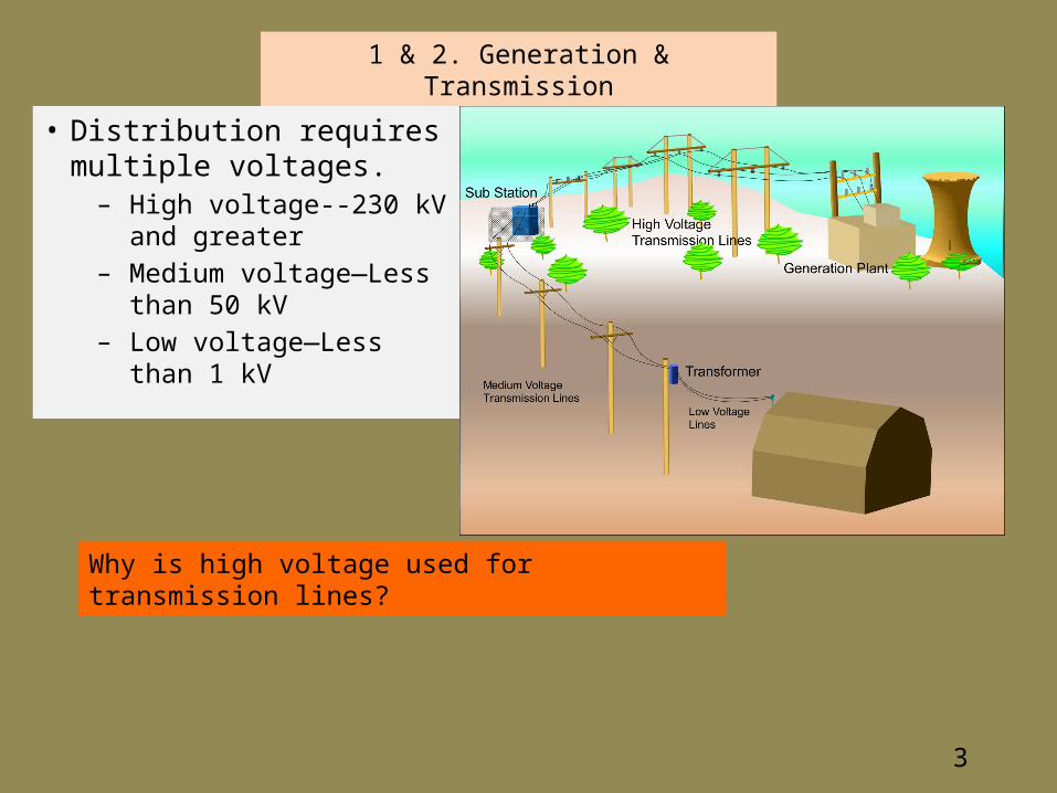
• Distribution requires multiple voltages.
– High voltage--230 kV and greater
– Medium voltage—Less than 50 kV
– Low voltage—Less than 1 kV
Why is high voltage used for transmission lines?
3
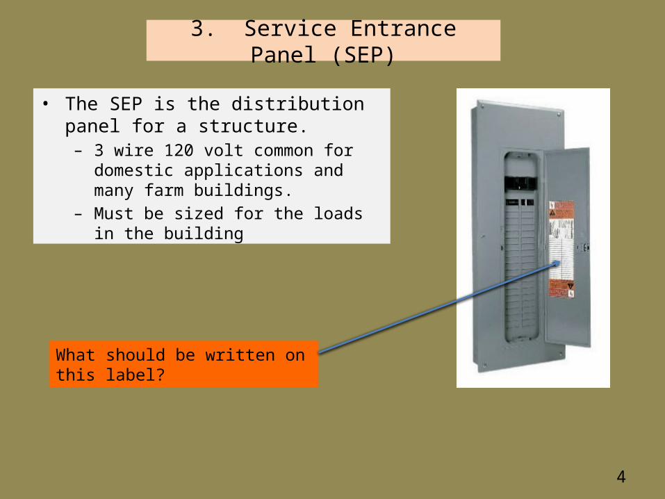
3. Service Entrance Panel (SEP)
• The SEP is the distribution panel for a structure.– 3 wire 120 volt common for domestic
applications and many farm buildings.– Must be sized for the loads in the building
What should be written on this label?
4

5
4. Conductors
Electrical conductors are constructed of either copper or aluminum.
Copper Aluminum
Advantages Disadvantages Advantages Disadvantages
High electrical conductivity
More expensive Lighter weight Requires larger diameter
Higher tensile strength
Become brittle if repeatedly flexed
Lower cost Requires special connectors
Higher Thermal conductivity
Increased chance of bimetal corrosion

6
Conductors – cont.
• Electrical conductors are size by AWG numbers.• The larger the number the smaller the diameter of wire.• The larger the diameter of wire the lower the
resistance.AWG Diameter (in) Ohms/1000 ft
10 0.1019 0.9989
12 0.0808 1.588
14 0.0641 2.525
16 0.0508 4.016
18 0.0403 6.385
20 0.0320 10.150
22 0.0254 16.140
24 0.0201 25.670
26 0.0159 40.810
What is AWG an abbreviation for?

7
• Common individual wires are:• XHHW• THWN• THHN
Conductors – cont.
• Conductors can be bundled into cables or used as individual wires.
• Common cables are:• NM-B (romex)• SE• Armored• UF
What to these letters stand for?
8
5. Connectors
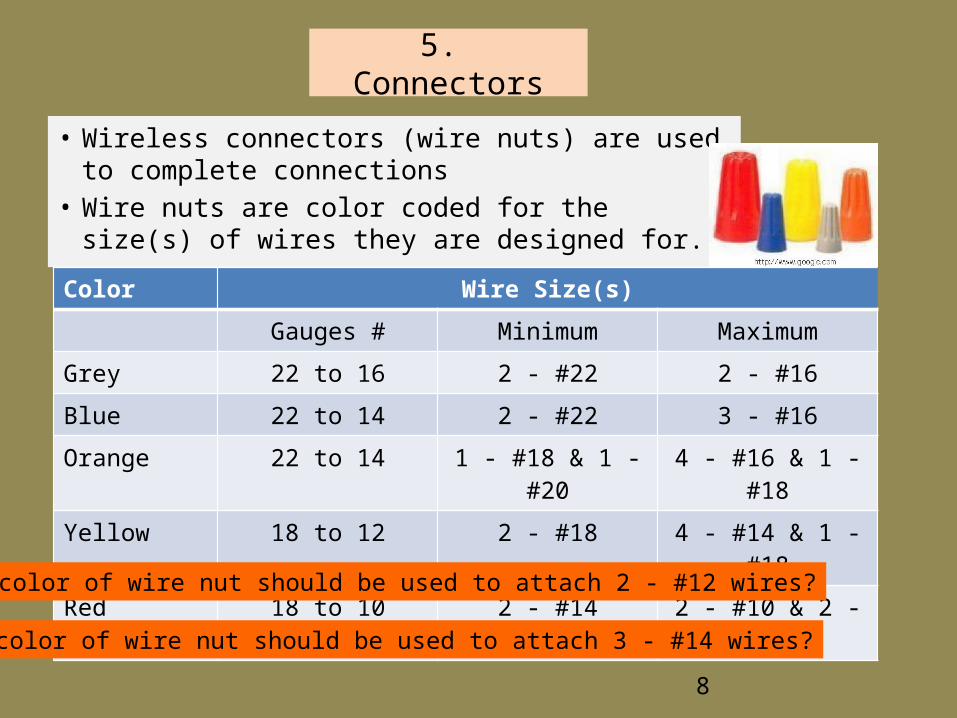
• Wireless connectors (wire nuts) are used to complete connections
• Wire nuts are color coded for the size(s) of wires they are designed for.
Color Wire Size(s)
Gauges # Minimum Maximum
Grey 22 to 16 2 - #22 2 - #16
Blue 22 to 14 2 - #22 3 - #16
Orange 22 to 14 1 - #18 & 1 - #20 4 - #16 & 1 - #18
Yellow 18 to 12 2 - #18 4 - #14 & 1 - #18
Red 18 to 10 2 - #14 2 - #10 & 2 - #12
What color of wire nut should be used to attach 3 - #14 wires?
What color of wire nut should be used to attach 2 - #12 wires?

9
6. Enclosures
Code requires that all electrical devices and connections must be installed inside an enclosure.
The NEMA has established standards for all electrical enclosures based on use and the environment.
NEMA standards have enclosure types for:Non hazardous locationsHazardous locations
10
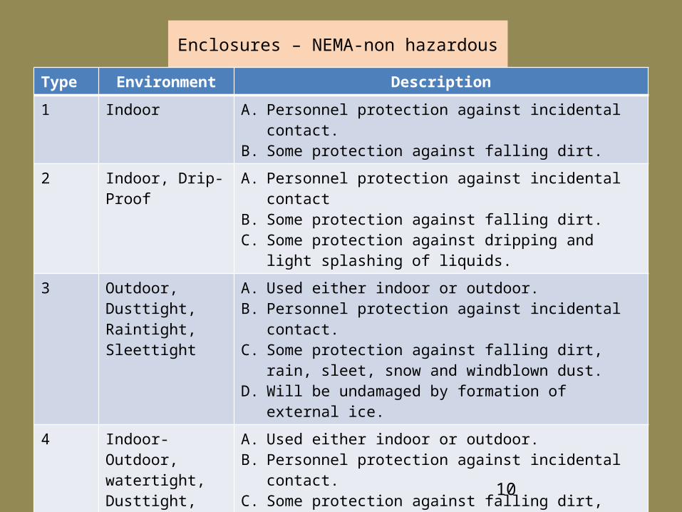
Enclosures – NEMA-non hazardousType Environment Description
1 Indoor A. Personnel protection against incidental contact.B. Some protection against falling dirt.
2 Indoor, Drip-Proof
A. Personnel protection against incidental contactB. Some protection against falling dirt.C. Some protection against dripping and light
splashing of liquids.
3 Outdoor, Dusttight, Raintight, Sleettight
A. Used either indoor or outdoor.B. Personnel protection against incidental contact.C. Some protection against falling dirt, rain, sleet,
snow and windblown dust.D. Will be undamaged by formation of external ice.
4 Indoor-Outdoor, watertight, Dusttight, sleet resistant
A. Used either indoor or outdoor.B. Personnel protection against incidental contact.C. Some protection against falling dirt, rain, sleet,
snow and windblown dust, splashing water, hose directed water and corrosion.
D. Will be undamaged by formation of external ice.
5, 6, 12, 13

11
7. Controls
• The primary need for agricultural buildings is devices to energize and de energize electrical circuits.
• The primary device used are switches.
• A switch is a electrical component that can interrupt the flow of electricity in a circuit or divert it from one conductor to another.

12
Building Groups

13
Building Groups
• Agricultural buildings are defined as any structure used to house farm implements, hay grain, animals or other agricultural produce.
– No habitation or product processing, treatment or packaging.• Agricultural buildings are categorized into three groups:
– Dry– Damp– Dusty
• Different environments have different electrical code requirements.
14
Building Groups—cont.
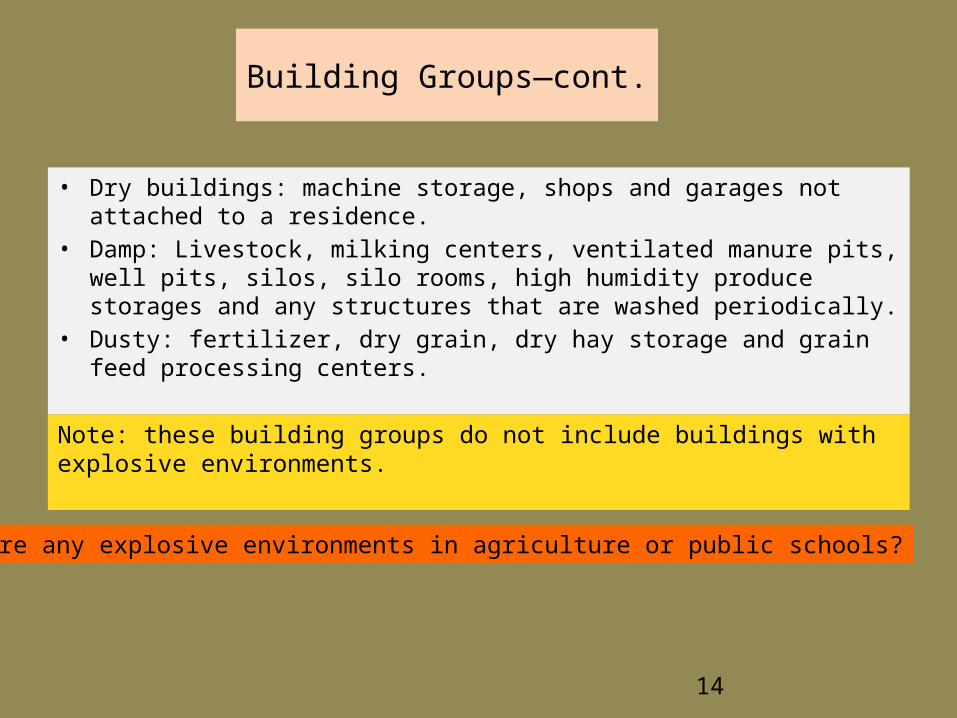
• Dry buildings: machine storage, shops and garages not attached to a residence.
• Damp: Livestock, milking centers, ventilated manure pits, well pits, silos, silo rooms, high humidity produce storages and any structures that are washed periodically.
• Dusty: fertilizer, dry grain, dry hay storage and grain feed processing centers.
Note: these building groups do not include buildings with explosive environments.
Are there any explosive environments in agriculture or public schools?

15
Building Materials for all Buildings
• For the safest electrical system, only use components approved by the Underwriters Laboratories Inc. (UL)
– Develops specification for minimum safety standards.– Specifications are based on building environments
http://assets.twacomm.com/ http://www.nobodybuy.com
Surface mount Waterproof

16
Building Groups--Dry
• Dry buildings do not require special electrical materials.
• Surface wiring is acceptable.
What are some concerns that must be address when surface wiring is used in agricultural buildings?
17
Building Groups—Dry—cont.
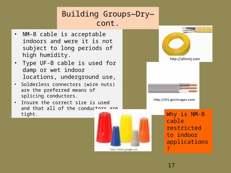
• NM-B cable is acceptable indoors and were it is not subject to long periods of high humidity.
• Type UF-B cable is used for damp or wet indoor locations, underground use, and out door locations.
• Solderless connectors (wire nuts) are the preferred means of splicing conductors.
• Insure the correct size is used and that all of the conductors are tight.
Why is NM-B cable restricted to indoor applications?

18
Building Group—Damp• Damp agricultural building require wiring practices, wire, fixtures
and devices engineered for that environment.• If surface wired, UF-B cable must be used.• High levels of moisture, dust and gas can quickly corrode metallic
equipment.• All boxes and fixtures must be dust and water tight, and corrosion
resistant. (Fig. 1-6 & 1-7)Why?

Building Group-Damp-Incandescent lights
Incandescent lights must use appropriate fixtures and heat resistant globes to cover the bulbs. (Fig. 1-4)
19

Building Group-Damp-Fluorescent lights
Fluorescent lights must use appropriate fixtures with gasketed cover. (Fig 1-5)
Also note the seal around the wire inlet.
20

Building Group-Damp—Wire Nuts
Solderless connectors used in damp environments must be designed for the environment.
What is the difference between wire nuts designed for damp environments compared to ones designed for wet environments??
21
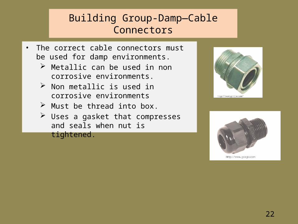
Building Group-Damp—Cable Connectors
• The correct cable connectors must be used for damp environments. Metallic can be used in non corrosive
environments. Non metallic is used in corrosive environments Must be thread into box. Uses a gasket that compresses and seals when
nut is tightened.
22

23
Building Group—Damp--Conduct
• PVC is the recommended conduct for damp buildings.– Available in different lengths up to 20 feet.– Available in diameters from ½ inch to 6 inches.
• Recommended conductors for plastic conduct include:– THWN– RHWN– THHW– XHHW
Table 1-4.
24
Building Group--Dusty
• Commercial dusty buildings such as grain elevators require additional precautions. [NEC 502.10(A)]
• On farm grain storage and handling facilities are usually wired according to the damp building requirements.

25
Building Group—Dusty-explosive
• Intrinsically safe circuits are used. – Current and voltage are limited so that the minimum ignition energy and the
ignition temperature of an explosive mixture cannot be reached.• The production of sparks, arcs or excessive temperatures which might act
as a source of ignition are prevented by additional measures and an increased degree of safety.– Use non sparking tools
• The components which could cause the ignition of a potentially explosive mixture are built into an enclosure which is capable of withstanding the pressure of an explosion. – It must be ensured that the explosion inside the enclosure cannot be
transmitted beyond the enclosure and ignite the external potentially explosive atmosphere

26
Box Size
• Box must have adequate volume for the devices and conductors.• Characteristics of inadequate box size.
– Difficult to work in– Increases work time– Concentrates heat– Increases chances of short circuits

27
Box Size—cont.
Box size is determined by multiplying the equivalent number of conductors by the conductor volume values in Table 1-2.
Conductor Size (AWG) Box Volume (Cubic inches per
conductor)14 2.0012 2.2510 2.508 3.006 5.00

28
Box Size—cont.• The number of equivalent conductors is determined by 8 criteria:
1 Each conductor that originates outside the box and terminates in it count as one.
2 Each conductor passing through a box without being spliced or connected to a device is counted as one conductor.
3 Each conductor that begins and ends in the same box are not counted.
4 All grounding conductors are counted as only one conductor unless a second set of equipment grounding conductors are used.
5 Up to four (4) fixture wires smaller than 14 AWG entering the box is ignored. Five or more are counted.
6 Each of the type of fitting or fixture in a box is counted as one conductor.
7 Each internal cable clamp is counted as one conductor.
8 A switch or receptacle strap is two conductors.

29
Box Size—cont.—box fittings
• Cable clamp
• Fixture stud
• Fixture strap

30
Box Size--Example
Determine the minimum size of box for the illustration when 12 AWG is used.
€
1. 2
2. 0
3. 0
4. 1
5. 0
6. 0
7. 2
8. 2EC 7
€
7 x 2.25 = 15.75 in3

31
Box Size—Example 2
Determine the minimum size of box for the illustration when 12 AWG is used.
€
1. 8
2. 0
3. 0
4. 1
5. 0
6. 1
7. 2
8. 0
EC 12
€
2.25 x 12 = 27.0 in3

32
Wires per Conduct
• The NEC limits the number of wires that can be installed in each size of conduct.
• For a size of conduct the limit is determined by the type of insulation and the wire size. (Table 1-5)

33
Electrical Box Wiring Requirements
1 Boxes must be securely fastened to building.
2 Cable or conduct must be clamped to the box.
3 Cables (conductors) must run inside walls, floors and ceilings and be attached close to the box and periodically along the length of the cable.
4 Metal boxes must be grounded.
5 Wires must be connected to each other using solderless connectors.
6 No more than one wire per terminal on switches, receptacle and other electrical devices. [Fig 33-4 not acceptable everywhere]
7 Hot wires are attached to brass colored screws.
8 Neutral wires are attached to aluminum colored screws.
9 Ground wires are attached to green colored screws.
10 When the white (neutral) conductor is used as a hot conductor (switch loop) it must be marked with black paint or tape.

34
The End