chapter three facility requirements - monett master plan...chapter three facility requirements...
TRANSCRIPT

Page 2.1H F J M a s t e r P l a n U p d a t e
F a c i l i t y R e q u i r e m e n t s
Page 3.1
Chapter Three Facility Requirements
INTRODUCTION
This chapter identifies the long-range airfield and terminal area facilities needed to satisfy the 20-year forecast of aviation demand at Monett Municipal Airport (HFJ). Facility needs have been identified based on the accumulation of inventory information, forecast aviation demand, and peak period activity analyses and planned in accordance with FAA airport design criteria. The identification of needed facilities does not constitute a requirement, but rather an option for facility improvements to resolve facility, operational or safety inadequacies, or to make improvements to the airside or landside components as aviation demand warrants.
PEAKING CHARACTERISTICS
The traffic demands imposed on an airport exhibit variations based on an annual, monthly, daily and hourly basis. These fluctuations result in periods of activity, known as peaks, which place the greatest amount of demand on airport facilities to accommodate aircraft and passengers. As the need for aviation services increases so, too, does the demand for individual facilities to accommodate peak periods of aviation-related activity. Peak periods must be considered when determining future facilities so that airfield and terminal area components are effectively utilized in order to accommodate projected demand.
The airport peaking characteristics analysis will forecast peak period demand for aircraft operations, as well as passenger activity at HFJ, taking into account normal periods of airport activity. This analysis is organized into peak month/average day and peak hour passenger estimates for the short (0-5 year), intermediate (6-10 year) and long-term (11-20 year) phases throughout the 20-year airport development period.
Peak Month/Average Day (PMAD) Demand Historical operational activity at HFJ was evaluated to identify trends of the aver-age day of the peak month. Typically, peak operations at general aviation airports such as HFJ occur during the months of July or August. Also, some airports, like HFJ, may have peak hour operations as high as 12 to 20 percent of daily total op-erations. It is assumed, due to projected regular operation at the Airport by locally based and transient turbine powered aircraft coupled with moderate local busi-ness and leisure activity, that approximately 2,700 operations, or nearly 16 percent of the total current activity, occurs during the peak months. This peak hour opera-tional trend is expected to continue throughout the 20-year planning period.
To arrive at the average day of peak month (Design Day) operational total, the PMAD activity was divided by the number of days in the peak month (30). Peak Hour operational projections are the result of the Design Day compared to the
3

H F J M a s t e r P l a n U p d a t ePage 2.2
F a c i l i t y R e q u i r e m e n t s
Page 3.2
ratio of activity occurring during the peak month. Table 3.1 summarizes the peak operational estimates for HFJ.
Table 3.1 PMAD Operational Demand, 2009-2029
Peaking Elements 2009 2014 2019 2024 2029
Annual Operational Demand 20,300 25,100 29,400 35,800 38,500
Peak Month (PMAD) Operations 3,200 4,000 4,700 5,700 6,200
Design Day (PMAD) Operations 110 130 160 190 210
Peak Hour Operations 18 21 26 30 34
Note: Figures rounded to the nearest tenth or hundred for planning purposes.
Source: BWR; HFJ Demand Forecasts.
Peak month operations at HFJ are projected to increase from approximately 3,200 to nearly 6,200 monthly operations in 2029. In 2009, HFJ is expected to experience approximately 110 design day operations. This activity level translates into 18 operations during peak hour periods and nine departures per peak hour. In 2029, the Airport is expected to experience as many as 210 design day operations and 34 peak hour operations totaling 17 departures per peak hour. Ultimately, operational peaking characteristics will have the most influence on apron area needs and the number of tie-down spaces to accommodate peak hourly demand at the facility.
Peak Hourly Passenger Activity Planning for the proper space allowances needed for terminal building facilities and passenger circulation requires hourly volumes of activity consistent with the average daily baseline of activity at an airport. Peak hourly passenger activity forecasts are generated by determining peak monthly passenger activity based on accurate enplanement estimates. In the case of HFJ, assumptions were made as to what the reasonable level of passenger traffic would be during peak periods of operational activity. Table 3.2 summarizes the peak hour passenger activity estimates for HFJ throughout the planning period.
Table 3.2 Peak Hour Passenger Demand, 2009-2029
Peaking Elements 2009 2014 2019 2024 2029
Annual Operational Demand 20,300 25,100 29,400 35,800 38,500
Peak Month Demand 3,200 4,000 4,700 5,700 6,200
Design Day Demand 110 130 160 190 210
Peak Hour Passengers 18 21 26 30 34
Note: Figures rounded to the nearest tenth or hundred for planning purposes.
Source: BWR; HFJ Demand Forecasts.
To determine the peak hourly activity, it was assumed that peak hour passenger activity would be similar to that of the peaking activity, or approximately 16 percent of average day activity. In terms of passenger and operational activity,

Page 2.3H F J M a s t e r P l a n U p d a t e
F a c i l i t y R e q u i r e m e n t s
Page 3.3
as airport activity increases, the peak of activity tends to spread out throughout the day. This fact shows that as aircraft operations increase so, too, does the level of passenger traffic. Absent historic passenger activity, the projected peak hour passenger totals are expected to reflect design day or peak operational trends at the facility. In 2009, HFJ is expected to experience approximately 18 peak hour passengers. Ultimately, the Airport is anticipated to accommodate 34 peak hour passengers during normal operating conditions.
AIRFIELD AND AIRSPACE REQUIREMENTS
The determination of airfield and airspace requirements includes an assessment of the airport’s ability to accommodate projected activity levels, analysis of its compliance with design and safety standards, and a determination of design standards for new facilities and/or the improvement of existing facilities. Airfield and airspace components include runway requirements such as dimensional criteria, length, width and pavement strength, as well as taxiway requirements, markings, lighting and AWOS needs.
Runway Requirements Existing and future runway needs will be examined with respect to dimensional criteria, orientation, length, width and pavement strength. Ultimate runway requirements for HFJ were prepared pursuant to FAA Advisory Circular (AC) 150/5300-13, Airport Design, Change 13 and FAA AC 150/5325-4B, Runway Length Requirements for Airport Design.
Dimensional Criteria The existing Airport Reference Code (ARC) for Runway 18-36, considering the existing length and safety area dimensions, is B-II. This ARC is expected to accommodate approximately 75 percent of the GA aircraft fleet weighing between 12,500 and 60,000 pounds at 60 percent useful load. The current critical aircraft for HFJ is a Cessna Citation Encore (ARC B-II) while the ultimate critical aircraft is a Cessna Citation X (ARC C-II). Accordingly, it is recommended that the ultimate safety dimensional criteria for HFJ be capable of safely accommodating 100 percent of the GA fleet weighing 12,500 to 60,000 lbs at 60 percent useful load, or ARC C-II. Table 3.3 illustrates the dimensional standards including those required for existing ARC B-II and future ARC C-II classifications for Runway 18-36.
Orientation For planning standards, the desirable wind coverage is 95 percent for the primary runway and is computed based on the crosswind component not exceeding 10.5 knots for ARC A-I aircraft. Small aircraft (weighing less than 12,500 lbs) are recommended to be able to operate approximately 95 percent of a given period without experiencing a crosswind component greater than 10.5 knots.
As indicated in Chapter 1, Wind Analysis, Runway 18-36 provides the necessary 95.3 percent wind coverage for small aircraft at 10.5 knots of crosswind. Therefore, it is recommended that the ultimate alignment of Runway 18-36 remain at its present bearing of 1.65 degrees to accommodate future small aircraft demand.
Dimensional CriteriaIt is recommended that the ultimate safety dimensional criteria for HFJ be capable of safely accommodating 100 percent of the GA fleet weighing 12,500 to 60,000 lbs at 60 percent useful load, or ARC C-II.
Runway OrientationIt is recommended that the ultimate alignment of Runway 18-36 remain at its present bearing of 1.65 degrees to accommodate future small aircraft demand.

H F J M a s t e r P l a n U p d a t ePage 2.4
F a c i l i t y R e q u i r e m e n t s
Page 3.4
Table 3.3 Existing and Ultimate Runway Dimensional Standards
Runway Item
Runway 18-36 (E) Standards (Ft.) ARC B-II
Runway 18-36 (U) Standards (Ft.) ARC C-II
Runway Width 75 100Runway Safety Area (RSA):RSA widthRSA length beyond runway end
150300
5001,000
Object Free Area (OFA):OFA widthOFA length beyond runway end
500300
8001,000
Obstacle Free Zone (ROFZ):ROFZ widthROFZ length beyond runway end
400200
400200
Runway Protection Zone (RPZ):Primary Runway EndInner Width Outer widthLength
5007001,000
1,0001,7502,500
Runway Protection Zone (RPZ):Other Runway EndInner Width Outer widthLength
5007001,000
5001,0101,700
Runway to Parallel Taxiway CLRunway CL to Aircraft Parking Runway to Taxiway Hold Line
240250200
400500250
Runway Safety Area (RSA): The RSA is a two-dimensional surface surrounding the runway prepared or suitable for reducing the risk of damage to airplanes in the event of undershoot, overshoot or excursion from the runway.Object Free Area (OFA): The OFA is a two-dimensional area on the ground centered on the runway, taxiway, or taxilane centerline provided to enhance the safety of aircraft operations by having the area free of objects, except for those that need to be located in the OFA for air navigation or aircraft ground maneuvering purposes.Runway Obstacle Free Zone (ROFZ): The OFZ is the airspace below 150 feet above the a established airport elevation and centered on the runway centerline that is required to be clear of all objects, except for frangible visual post mounted NAVAIDS expressly located in the OFZ by function, in order to provide clearance protection for aircraft landing or taking off from the runway and for missed approaches. Runway Protection Zone (RPZ): The purpose of the RPZ is to enhance the protection of people and property on the ground, and to prevent obstructions to aircraft. The RPZ is a two-dimensional trapezoid area beginning 200 feet beyond the paved runway end, and extends along the runway centerline. The RPZ size is determined by the aircraft approach category of airplanes expected to utilize the airport, as well as the type of instrument approach or minimum visibility to the runway ends. The FAA recommends that airport sponsor own the RPZ property in fee simple, and that the RPZ be clear of any non-aeronautical structure of public assembly or object that would interfere with the arrival and departure of aircraft.
Source: FAA AC 150/5300-13, Airport Design, Change 13.

Page 2.5H F J M a s t e r P l a n U p d a t e
F a c i l i t y R e q u i r e m e n t s
Page 3.5
Length The determination of runway length requirements for general aviation airports such as HFJ is derived from FAA AC 150/5325-4B, Runway Length Requirements for Airport Design.
Runway lengths for small aircraft (less than 12,500 lbs.) consider performance curves of propeller and some turbo-prop aircraft including maximum takeoff and landing weights; headwind component; optimal flap settings for normal operations; elevation above mean sea level; and mean maximum daily temperature for the airport.
Runway lengths for large aircraft (12,500 lbs. up to 60,000 lbs.) consider performance curves derived from FAA-approved flight manuals for turbo-prop and business jet aircraft developed in accordance with provisions of Federal Aviation Regulation (FAR) Part 25, Airworthiness Standards: Transport Category Airplanes and Part 91, General Operating and Flight Rules. Landing and takeoff operational adjustments such as load factor, runway gradient and pavement conditions are those variables which have the most influence on runway length requirements for large aircraft. Runway length for large aircraft at HFJ is recommended to accommodate 100 percent of the GA aircraft fleet at 60 percent useful load on takeoff.
Table 3.4 illustrates the runway length requirements for HFJ taking into consideration varying operational variables.
Table 3.4 Runway Length Requirements, 2009-2029
Airport and Runway Data Variable
Airport elevation (mean sea level- MSL)Mean daily maximum temperature of the hottest monthCritical AircraftMaximum difference in runway centerline elevationPavement ConditionsPercent of Fleet/Useful Load (%)
1,314 feet87° FCessna Citation X (ARC C-II)16 feetWet and Slippery100/60
Runway Lengths for Airplanes w/ MTOW of ≥12,500 lbs. up to 60,000 lbs. Length (Feet)
Runway 18-36 Existing lengthRunway 18-36 (100% of GA Fleet at 60% Useful Load)Runway 18-36 (Runway Gradient-0.3%)Runway 18-36 (Wet Pavement Condition)*
5,0005,7005,9005,500*
MTOW- Maximum Takeoff Weight(*) Runway length requirements for jet powered airplanes obtained from the “60 percent useful load” curves are increased by 15 percent or up to 5,500 feet, whichever is less.
Source: FAA AC 150/5325-4B, Runway Length Requirements for Airport Design.
Runway LengthUltimately, considering runway grade and HFJ’s future critical aircraft, which is expected to be an ARC C-II aircraft, the usable length of Runway 18-36 is recommended to be 5,900 feet.

H F J M a s t e r P l a n U p d a t ePage 2.6
F a c i l i t y R e q u i r e m e n t s
Page 3.6
Ultimately, considering runway grade and HFJ’s future critical aircraft, which is expected to be an ARC C-II aircraft, the usable length of Runway 18-36 is recommended to be 5,900 feet.
Width The required runway width is a function of approach visibility minimums and the facility’s ARC. The ARC is a combination of the critical airplane’s approach category (approach speed) and airplane design group (wingspan). The current 75-foot width of Runway 18-36 is recommended to be widened an additional 25 feet. The ultimate 100-foot width will be sufficient to accommodate ARC C-II aircraft throughout the planning period.
Pavement Design Strength The required pavement design strength is an estimate based on average levels of activity and is expressed in terms of aircraft landing gear type and geometry (i.e., load distribution). The pavement design strength is not the maximum allowable weight. Limited operations by aircraft heavier than the critical aircraft may be permissible.
HFJ’s ultimate critical aircraft, the Citation X, has a MTOW of nearly 34,500 lbs. For Runway 18-36, the current weight bearing capacity of 30,000 pounds for single wheel gear (SWG) aircraft is recommended to be upgraded to 45,000 SWG to accommodate the ultimate critical aircraft.
Taxiway Requirements The taxiway system exists expressly to serve as a defined area to accommodate the movement of aircraft to and from the runway, as well as to serve as a tran-sit system between the airside and terminal area. This section will evaluate the capability of the future taxiway system at HFJ to accommodate ultimate demand activity.
HFJ’s taxiway system was previously described in Chapter 1, Table 1.2 and depicted on Exhibit 1.2. Based on projected operational demand, the existing taxiway width of 35 feet for ARC C-II aircraft is sufficient to accommodate projected demand. Ultimately, the runway centerline to taxiway centerline separation distance is recommended to be a minimum of 400 feet for the parallel taxiway.
Navigational Aids (NAVAIDs)/Communications NAVAIDs are installed on or near airports to increase the reliability and efficiency to accommodate aircraft operations during night and inclement weather con-ditions. NAVAIDs utilized at HFJ were described in Chapter 1, Airfield Facilities. Ultimately, HFJ is recommended to be served by its existing RNAV(GPS) and LPV approaches utilizing Wide Area Augmentation System (WAAS) technology.
WAAS Emerging technologies including WAAS, as well as Local Area Augmentation System (LAAS), are expected to replace the ILS as the primary means of establishing precision instrument approaches. LAAS is an augmentation to GPS signals that is focused on a 20 to 30 mile radius around an airport with
Runway WidthThe current 75-foot width of Runway 18-36 is recommended to be widened an additional 25 feet. The ultimate 100-foot width will be sufficient to accommodate ARC C-II aircraft throughout the planning period.
Pavement Design StrengthFor Runway 18-36, the current weight bearing capacity of 30,000 pounds for single wheel gear (SWG) aircraft is recommended to be upgraded to 45,000 SWG to accommodate the ultimate critical aircraft.
Taxiway RequirementsBased on projected operational demand, the existing taxiway width of 35 feet for ARC C-II aircraft is sufficient to accommodate projected demand. Ultimately, the runway centerline to taxiway centerline separation distance is recommended to be a minimum of 400 feet for the parallel taxiway.
NAVAIDs/CommunicationsUltimately, HFJ is recommended to be served by its existing RNAV(GPS) and LPV approaches utilizing Wide Area Augmentation System (WAAS) technology.

Page 2.7H F J M a s t e r P l a n U p d a t e
F a c i l i t y R e q u i r e m e n t s
Page 3.7
LAAS capabilities. LAAS is broadcast via a VHF radio data link from a ground based transmitter yielding highly accurate information to accommodate ½-mile visibility minimum instrument approaches. WAAS utilizes the same technology as that of LAAS but affords an even larger operational area providing enhanced GPS services to airports within a 200 to 300 mile area.
Because future precision instrument approach capabilities are expected to be accommodated by satellite-based GPS applications, traditional instrument landing system (ILS) components such as the localizer antenna (LOC), glide slope antenna (GS), marker beacons (outer marker- OM, middle marker- MM and inner marker- IM), with the exception of the approach lighting system, are expected to be obsolete for establishing precision instrument approach capabilities. However, because precision capabilities require stringent safety area and structure clearance criteria, WAAS procedures will exhibit the same standards associated with airfield dimensional guidelines as those associated with an ILS. (RNAV)GPS procedures such as LPV and lateral and vertical navigation (LNAV/VNAV) approaches utilize WAAS technology to accommodate published instrument approaches.
Remote Communications Outlet (RCO) HFJ’s RCO was described in Chapter 1, Airfield Facilities. HFJ’s RCO is recommended to remain in place for the foreseeable future and upgraded as necessary throughout the planning period.
Markings, Lighting and AWOS
Airfield Markings Airfield markings were previously described in Chapter 1, Table 1.2. Ultimately, Runway 18-36 is recommended to be marked as precision instrument (PI) runway given existing and future (RNAV)GPS and Lateral Precision with Vertical Guidance (LPV) instrument approach procedures to the Airport. Future approach procedures are intended to have minimum visibilities as low as ½-mile with cloud ceiling minimums not lower than 200 feet above ground level. Taxiways, taxilanes and apron areas are recommended to be marked in accordance with FAA AC 150/ 5340-1J, Standards for Airport Markings.
Airfield Lighting Airfield lighting at HFJ was described in Chapter 1, Airfield Facilities. This section will offer additional information and explanation regarding lighting systems utilized at HFJ.
Runway and Taxiway Lighting: Runway 18-36 is recommended to maintain the pilot-controlled, white, stake mounted, Medium Intensity Runway Lighting (MIRL), as well as the red and green omni-directional threshold lights. Proposed runway lighting upgrades are recommended to include high intensity runway lighting (HIRL) to accommodate PI approaches to the runway.
Ultimately, the taxiway system serving Runway 18-36 is recommended to be continuously equipped with blue medium
Remote Communications OutletHFJ’s RCO is recommended to remain in place for the foreseeable future and upgraded as necessary throughout the planning period.
Markings, Lighting, and AWOSUltimately, Runway 18-36 is recommended to be marked as precision instrument (PI) runway given existing and future (RNAV)GPS and Lateral Precision with Vertical Guidance (LPV) instrument approach procedures to the Airport. Future approach procedures are intended to have minimum visibilities as low as ½-mile with cloud ceiling minimums not lower than 200 feet above ground level.
Runway and Taxiway LightingRunway 18-36 is recommended to maintain the pilot-controlled, white, stake mounted, Medium Intensity Runway Lighting (MIRL), as well as the red and green omni-directional threshold lights. Proposed runway lighting upgrades are recommended to include high intensity runway lighting (HIRL) to accommodate PI approaches to the runway.
Ultimately, the taxiway system serving Runway 18-36 is recommended to be continuously equipped with blue medium intensity taxiway lighting (MITL).

H F J M a s t e r P l a n U p d a t ePage 2.8
F a c i l i t y R e q u i r e m e n t s
Page 3.8
intensity taxiway lighting (MITL).
Runway End Indicator Lights (REILs): REILs include high intensity, photo strobe lights used for rapid identification of the thresholds during night and inclement weather conditions. Ultimately, Runway 18-36 is recommended to retain the REILs servicing both runway approach ends.
Visual Guidance Indicators: Precision Approach Path Indicators (PAPI) emit a sequence of colored light beams providing continuous visual descent guidance information along the desired final approach descent path (normally at 3 degrees for 3 nautical miles during daytime, and up to 5 nautical miles at night) to the runway touchdown point. Runway 18-36 is recommended to be continuously served by a PAPI-4L system throughout the planning period.
Approach Lighting Systems: An approach lighting system is utilized in conjunction with existing and future instrument approach procedures with minimum visibilities less than 1-mile to aid in identifying the airport environment while conducting approaches during IFR weather conditions. Runway 36 is currently equipped with a medium intensity approach lighting system with flashing lights (MALSF). Ultimately, the MALSF is recommended to be upgraded to a medium intensity approach lighting system with runway alignment indicator lights (MALSR) to accommodate minimum approach visibilities not lower than ½-mile to the Runway 36 threshold. Additionally, HFJ’s existing MALSF and proposed MALSR are recommended to be maintained and operated in accordance with FAA Order 6850.2A, Visual Guidance Lighting Systems.
Airport Beacon: HFJ’s airport beacon provides visual airport identification and location during night-time operations, as well as during inclement weather conditions. It is recommended that the current airport beacon be maintained in its current location for the foreseeable future and replaced when necessary during the planning period.
AWOS HFJ’s automated weather observation system was described in Chapter 1, Airfield Facilities. HFJ’s AWOS is recommended to be relocated within the short-term (0-5 year) planning period from its current location to the west side of the airfield. This is so that the AWOS’ system sensors are not obstructed by man-made or natural objects. HFJ’s AWOS is also recommended to maintain its interface with the National Weather Service to provide updated and accurate weather conditions to local and transient aircraft. Continued interface will also ensure continuity of existing and future published approach procedures.
REILsUltimately, Runway 18-36 is recommended to retain the REILs servicing both runway approach ends.
Airport BeaconIt is recommended that the current airport beacon be maintained in its current location for the foreseeable future and replaced when necessary during the planning period.
Approach Lighting SystemsUltimately, the MALSF is recommended to be upgraded to a medium intensity approach lighting system with runway alignment indicator lights (MALSR) to accommodate minimum approach visibilities not lower than ½-mile to the Runway 36 threshold. Additionally, HFJ’s existing MALSF and proposed MALSR are recommended to be maintained and operated in accordance with FAA Order 6850.2A, Visual Guidance Lighting Systems.
Visual Guidance IndicatorsRunway 18-36 is recommended to be continuously served by a PAPI-4L system throughout the planning period.
AWOSHFJ’s AWOS is recommended to be relocated within the short-term (0-5 year) planning period from its current location to the west side of the airfield. This is so that the AWOS’ system sensors are not obstructed by man-made or natural objects. HFJ’s AWOS is also recommended to maintain its interface with the National Weather Service to provide updated and accurate weather conditions to local and transient aircraft. Continued interface will also ensure continuity of existing and future published approach procedures.

Page 2.9H F J M a s t e r P l a n U p d a t e
F a c i l i t y R e q u i r e m e n t s
Page 3.9
Airspace Requirements Exhibit 3.1 depicts typical FAR Part 77 imaginary airspace surfaces including the primary surface, horizontal surface, transitional surfaces, and approach surfaces. Most importantly, the approach surface is a three-dimensional trapezoidal-shaped imaginary surface beyond each runway end having a defined slope. The three slopes for an approach are 20:1, 34:1 and 50:1. The purpose of the approach surface is to provide proper clearance over structures and objects beyond the runway threshold for the safe approach and landing of aircraft based on a speci-fied approach path.
HFJ’s published approach procedures were described in Chapter 1, Table 1.1. Currently, Runway 18-36 has published 34:1 non-precision approaches to the Runway 18 and 36 thresholds. Given the operational characteristics of the future critical aircraft, coupled with the projected piston and turbine aircraft demand at the facility throughout the planning period, 34:1 NPI approaches are recommended to remain in place for both runway thresholds. Should the Airport elect to pursue establishment of precision instrument approach procedures, a 50:1 approach surface would be recommended.
Potential establishment of additional instrument approach procedures to Runway 18-36 require consideration and an analysis of the wind conditions during instrument meteorological conditions (IMC). Exhibit 3.2 illustrates the Airport’s IMC wind rose which depicts the predominant wind directions and velocities occurring at HFJ. Based on the IMC wind analysis, it is recommended that future instrument approach procedures, particularly a 50:1 precision approach, be maintained and/or established primarily to the Runway 36 threshold.
AIRFIELD AND AIRSPACE FACILITY REQUIREMENTS SUMMARY
Table 3.5 summarizes the airfield/airspace facility requirements for HFJ. Items identified within Table 3.5 are those that require upgrade or expansion according to design criteria and are based on projected aviation demand.
Airspace RequirementsGiven the operational characteristics of the future critical aircraft, coupled with the projected piston and turbine aircraft demand at the facility throughout the planning period, 34:1 NPI approaches are recommended to remain in place for both runway thresholds. Should the Airport elect to pursue establishment of precision instrument approach procedures, a 50:1 approach surface would be recommended.
Based on the IMC wind analysis, it is recommended that future instrument approach procedures, particularly a 50:1 precision approach, be maintained and/or established primarily to the Runway 36 threshold.

H F J M a s t e r P l a n U p d a t ePage 2.10
F a c i l i t y R e q u i r e m e n t s
Page 3.10
Table 3.5 Airfield/Airspace Facility Requirements Summary, 2009-2029
Facility Type Recommendations
Airfield Dimensional Criteria/Orientation
Runway 18-36 Upgrade to ARC C-II design standards; Maintain true bearing of 1.65°
Runway Dimensions (length and width)
Runway 18-36 (5,000’ x 75’) Lengthen to 5,900 feet; Widen to 100 feet
Pavement Design Strength
Runway 18-36 Strengthen to 45,000 lbs. SWG
Taxiway Requirements
Runway 18-36 Taxiway System Maintain 35 foot width; 400 foot runway to taxiway centerline separation distance
NAVAID/Communications Requirements
WAAS/RCO Maintain RNAV(GPS) approaches; Maintain RCO in current location and condition
Airfield Markings
Runway 18-36 Upgrade to precision instrument (PI) markings
Lighting Requirements
Runway 18-36Upgrade MIRL to HIRL; Maintain threshold lights, REILs and PAPI-4Ls; Maintain MITL; Upgrade MALSF to MALSR
AWOS Requirements
AWOS Relocate AWOS-III to the west side of airfield
Airspace Requirements
Runway 18-36 Establish ultimate 50:1 (RNAV)GPS IAPs to Runway 36 threshold
Source: BWR; HFJ Airfield and Airspace Facility Requirements.
TERMINAL AREA REQUIREMENTS
Terminal area facility components are comprised of the passenger terminal building, auto parking, aircraft hangars, aircraft parking apron, as well as support facilities including fuel storage capabilities, snow removal and equipment (SRE) structures and aircraft maintenance.
Passenger Terminal Building The primary objective of the terminal building is to achieve an acceptable balance between passenger convenience, facility operational efficiency, facility investment and aesthetics. A well conceived terminal building should allow passengers to transition from the surface transportation mode to the air transportation mode with a minimum of inconvenience. Potential expansion of the terminal building should be developed and constructed within allowable funding levels that take into consideration the capital investment costs, as well as operational and maintenance costs.

Exhibit 3.1 – Part 77 Imaginary Airspace Surfaces

Exhi
bit 3
.1 –
Par
t 77
Imag
inar
y A
irspa
ce
Surf
aces
Page 2.13H F J M a s t e r P l a n U p d a t e
F a c i l i t y R e q u i r e m e n t s
Page 3.13
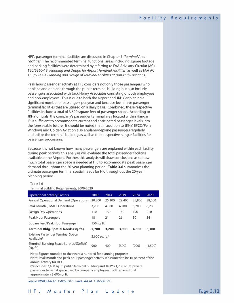
HFJ’s passenger terminal facilities are discussed in Chapter 1, Terminal Area Facilities. The recommended terminal functional areas including square footage and parking facilities were determined by referring to FAA Advisory Circular (AC) 150/5360-13, Planning and Design for Airport Terminal Facilities, as well as FAA AC 150/5390-9, Planning and Design of Terminal Facilities at Non-Hub Locations.
Peak hour passenger activity at HFJ considers not only those passengers who enplane and deplane through the public terminal building but also include passengers associated with Jack Henry Associates consisting of both employees and non-employees. This is due to both the airport and JKHY enplaning a significant number of passengers per year and because both have passenger terminal facilities that are utilized on a daily basis. Combined, these respective facilities include a total of 3,600 square feet of passenger space. According to JKHY officials, the company’s passenger terminal area located within Hangar ‘B’ is sufficient to accommodate current and anticipated passenger levels into the foreseeable future. It should be noted that in addition to JKHY, EFCO/Pella Windows and Golden Aviation also enplane/deplane passengers regularly and utilize the terminal building as well as their respective hangar facilities for passenger processing.
Because it is not known how many passengers are enplaned within each facility during peak periods, this analysis will evaluate the total passenger facilities available at the Airport. Further, this analysis will draw conclusions as to how much total passenger space is needed at HFJ to accommodate peak passenger demand throughout the 20-year planning period. Table 3.6 summarizes the ultimate passenger terminal spatial needs for HFJ throughout the 20-year planning period.
Table 3.6 Terminal Building Requirements, 2009-2029
Operational Activity/Factors 2009 2014 2019 2024 2029
Annual Operational Demand (Operations) 20,300 25,100 29,400 35,800 38,500
Peak Month (PMAD) Operations 3,200 4,000 4,700 5,700 6,200
Design Day Operations 110 130 160 190 210
Peak Hour Passengers 18 21 26 30 34
Square Feet/Peak Hour Passenger 150 sq. ft.
Terminal Bldg. Spatial Needs (sq. ft.) 2,700 3,200 3,900 4,500 5,100
Existing Passenger Terminal Space Available* 3,600 sq. ft.*
Terminal Building Space Surplus/(Deficit) (sq. ft.) 900 400 (300) (900) (1,500)
Note: Figures rounded to the nearest hundred for planning purposes.Note: Peak month and peak hour passenger activity is assumed to be 16 percent of the annual activity for HFJ.(*) Includes 2,400 sq. ft. public terminal building and JKHY’s 1,200 sq. ft. private passenger terminal space used by company employees. Both spaces total approximately 3,600 sq. ft.
Source: BWR; FAA AC 150/5360-13 and FAA AC 150/5390-9.

H F J M a s t e r P l a n U p d a t ePage 2.14
F a c i l i t y R e q u i r e m e n t s
Page 3.14
Based on current planning standards, the main terminal building can safely and comfortably accommodate 16 peak hour passengers (150 sq. ft. per passenger). Also, JKHY’s passenger terminal can adequately accommodate approximately eight passengers during peak periods. Ultimately, the passenger terminal facilities at HFJ are expected to have a 1,500 square foot deficit at the conclusion of the planning period, or 2029. Currently, the Airport has a surplus of approximately 900 square feet for passenger processing. This trend is expected to continue throughout the short (0-5 years) and intermediate (6-10 years) planning periods. During the first half of the long-term planning phase (11-20 years), HFJ, based on peak hour passenger projections, is expected to have a deficit of 300 square feet for passenger processing.
It is recommended that the City and on-airport businesses continuously monitor peak and/or annual passenger trends to evaluate potential expansion needs. It is supposed that during the master plan period (2019) the main airport terminal building will require expansion and/or renovations to accommodate increased passenger activity. Constant monitoring of passenger activity will be particularly important for the terminal building so that it will continue to adequately serve local and transient passengers and airport patron’s needs.
Auto Parking Public auto parking space requirements are based on FAA AC 150/5360-13. In determining the future auto parking needs, 1.5 spaces are allotted per peak hour passenger while 400 square feet per parking space, including maneuvering area, is provided. Table 3.7 summarizes the ultimate auto parking needs during normal airport operating conditions.
Auto parking requirements for HFJ consider parking spaces and maneuvering area needed for local and transient airport users. Currently, auto parking is provided within a 20,700 square foot shared space providing 51 auto parking stalls for both the airport terminal building and JKHY. JKHY also has an additional 75 parking spaces totaling 27,200 square feet located north of JKHY’s hangar ‘B’. This parking
Terminal Building ExpansionIt is recommended that the City and on-airport businesses continuously monitor peak and/or annual passenger trends to evaluate potential expansion needs. It is supposed that during the master plan period (2019) the main airport terminal building will require expansion and/or renovations to accommodate increased passenger activity. Constant monitoring of passenger activity will be particularly important for the terminal building so that it will continue to adequately serve local and transient passengers and airport patron’s needs.
Auto Parkingthe existing auto parking area is believed to be sufficient to accommodate peak hour passenger and parking demand through 2029.
Table 3.7 Auto Parking Requirements, 2009-2029
Operational Activity/Factors 2009 2014 2019 2024 2029
Peak Hour Passengers 18 21 26 30 34
Parking Spaces/Peak Hour Passenger 1.5 parking spaces
Total Parking Demand (Spaces) 27 32 39 45 51
Square Footage/Parking Space 400 square feet
Total Parking Area Demand (sq. ft.) 10,800 12,800 15,600 18,000 20,400
Existing Auto Parking Facilities 51 parking spaces/20,700 square feet
Parking Space Surplus (Spaces) 24 19 12 6 -
Parking Area Surplus (sq. ft.) 9,900 7,900 5,100 2,700 300
Note: Figures rounded to the nearest hundred for planning purposes.
Source: BWR; FAA AC 150/5360-13.

Page 2.15H F J M a s t e r P l a n U p d a t e
F a c i l i t y R e q u i r e m e n t s
Page 3.15
Ultimately, HFJ’s terminal building auto parking facilities are expected to have a surplus of 300 square feet of parking area at the conclusion of the planning period. Additionally, in 2029, the Airport is expected to have just enough parking stalls to accommodate projected demand of 51 parking spaces for peak hour auto parking activity. Based on this information, the existing auto parking area is believed to be sufficient to accommodate peak hour passenger and parking demand through 2029.
Aircraft Hangars T-Hangar facilities located at HFJ and corresponding square footage estimates were discussed in Chapter 1, Table 1.3. Hangar storage requirements will include a determination of recommended number of future hangar spaces and spatial requirements for T-hangars and clear span or box hangars. The HFJ demand fore-casts project 72 based aircraft including 48 single engine, eight twin-piston, four multi-engine turbo-props and 12 business jets in 2029.
T-Hangars In determining the ultimate T-hangar storage requirements for HFJ, it was assumed that 95 percent of the based single and multi-engine piston powered aircraft would be provided enclosed T-hangar space in the future. However, this assumption may differ from actual future hangar arrangements. Generally, single engine aircraft require approximately 1,250 square feet of space. Table 3.8 summarizes the T-hangar storage requirements for HFJ throughout the planning period.
Table 3.8 T-Hangar Requirements, 2009-2029
Operational Activity/Factors 2009 2014 2019 2024 2029
Based Aircraft* 29 36 42 51 56
Square Footage/Aircraft 1,250 square feet
T-Hangar Demand (Spaces)** 28 34 40 48 53
T-Hangar Area Demand (sq. ft.) 35,000 42,500 50,000 60,000 66,300
Existing T-Hangar Facilities 20 T-hangar units/26,940 square feet
T-Hangar Space Surplus/(Deficit) (8) (14) (20) (28) (33)
T-Hangar Area Surplus/(Deficit) (sq. ft.) (8,100) (15,600) (23,100) (33,100) (39,400)
Note: Figures rounded to the nearest hundred for planning purposes. (*) Includes single and multi–engine piston aircraft and excludes multi-engine turbine aircraft as they will most likely be stored in clear span or box hangars. (**) Indicates 95 percent of local single and multi-engine piston based aircraft. Two to three piston powered aircraft per planning phase will most likely be stored on the apron.
Source: BWR.
area is utilized by enplaning and deplaning company employees and flight department staff.
According to company representatives, this private parking area is adequate for current and future demand.
T-Hangar ExpansionBy 2029, it is recommended that an additional 39,400 square feet and 33 T-hangar units be developed to accommodate projected single and twin-piston based aircraft demand.
To meet this demand, as well as potential demand beyond forecasted levels, the Airport is recommended to develop four additional 10-unit T-hangar structures totaling approximately 50,000 square feet of space.

H F J M a s t e r P l a n U p d a t ePage 2.16
F a c i l i t y R e q u i r e m e n t s
Page 3.16
By 2029, it is recommended that an additional 39,400 square feet and 33 T-hangar units be developed to accommodate projected single and twin-piston based aircraft demand. Ultimately, HFJ is expected to accommodate approximately 53 total T-hangar storage spaces totaling nearly 66,300 square feet of space. To meet this demand, as well as potential demand beyond forecasted levels, the Airport is recommended to develop four additional 10-unit T-hangar structures totaling approximately 50,000 square feet of space.
Clear Span Hangars JKHY currently owns and maintains two clear span hangars totaling approximately 24,900 square feet of gross floor space. Actual aircraft hangar storage and maintenance area totals approximately 18,700 square feet and accommodates JKHY’s four Cessna Citation Encores. According to company officials, JKHY has additional land leases in place in order to expand their operation, including development of additional hangars, at HFJ should the need arise. Based on existing and anticipated conditions, the current aircraft storage space is adequate to accommodate JKHY’s operational tempo and is expected to remain so into the foreseeable future.
EFCO/Pella Windows also leases a 5,800 square foot hangar at HFJ to store the company’s Lear 45 for nearly four months throughout the year. Based on existing and anticipated operational trends, this hangar space is adequate to meet EFCO’s aircraft storage needs into the foreseeable future.
Golden Aviation, considering the company’s long-term Department of Defense contract to modernize piston and jet powered aircraft for foreign and domestic militaries, currently has approximately 5,000 square feet of floor space for aircraft storage. Ultimately, according to company officials, Golden has the potential need for eight clear span hangars totaling nearly 40,000 square feet, or 5,000 square feet per hangar. These spatial demands are those in addition to the current 12,000 square foot expansion taking place to the existing Golden Aviation building. Additionally, the company is expected to base three business jets and two turbo-props at HFJ during the planning period. Golden’s manufacturing and aircraft assembly building needs will be discussed later in this chapter.
Combined, HFJ’s on-airport businesses are expected to operate a total of eight business jets (JKHY-4; EFCO-1; and Golden Aviation-3) and two turbo-props (Golden Aviation).
In determining the ultimate clear span storage requirements for HFJ, it is assumed that future based turbine-powered aircraft will be stored in privately-owned clear span hangars that are not associated with current on-airport businesses or their respective based aircraft demands. This assumption, however, may differ from actual future hangar arrangements. Table 3.9 summarizes the clear span hangar storage requirements for HFJ throughout the planning period which is ultimately expected to include facility needs for two turbo-props and four business jets.
Clear Span Hangar ExpansionBy 2029, it is recommended that an additional 22,000 square feet and four new clear span hangars be developed, in addition to the 8,000 square feet provided by the City-owned hangar ‘B’, to accommodate projected turbine demand at the facility. Ultimately, HFJ is expected to accommodate a total of six clear span hangars totaling nearly 30,000 square feet of space.

Page 2.17H F J M a s t e r P l a n U p d a t e
F a c i l i t y R e q u i r e m e n t s
Page 3.17
Table 3.9 Clear Span Hangar Requirements, 2009-2029
Operational Activity/Factors 2009 2014 2019 2024 2029
Based Turbo-Prop Demand* 2 2 2 2 2
Based Business Jet Demand* 2 2 3 3 4
Total Turbine Aircraft Demand* 4 4 5 5 6
Square Footage/Aircraft and/or Hangar** 5,000 square feet
Clear Span Hangar Demand (Spaces) 4 4 5 5 6
Clear Span Hangar Demand (sq. ft.) 20,000 20,000 25,000 25,000 30,000
Existing Clear Span Hangar Facilities*** One/8,000 square feet
Clear Span Hangar Surplus/(Deficit) (3) (3) (4) (4) (5)
Clear Span Hangar Area Surplus/(Deficit) (sq. ft.) (12,000) (12,000) (17,000) (17,000) (22,000)
Note: Figures rounded to the nearest hundred for planning purposes. (*) Assumes future based turbine aircraft will be stored in privately-owned clear span hangars that are not associated with current on-airport businesses or their hangars. (**) A generously equipped clear span hangar totals approximately 5,000 square feet of space and/or measures approximately 71’ x 71’. (***) City-owned hangar ‘B’ which stores privately owned based airplanes.
Source: BWR.
By 2029, it is recommended that an additional 22,000 square feet and four new clear span hangars be developed, in addition to the 8,000 square feet provided by the City-owned hangar ‘B’, to accommodate projected turbine demand at the facility. Ultimately, HFJ is expected to accommodate a total of six clear span hangars totaling nearly 30,000 square feet of space.
Apron Areas and Tie-Downs Apron facilities and corresponding square yardage estimates located at HFJ were discussed in Chapter 1, Terminal Area Facilities. In determining the ultimate apron requirements for HFJ, tie-down spaces, maneuvering area, wingtip clearance and overall spatial needs were determined for the public portion of the existing and future aircraft apron which currently measures approximately 16,800 square yards.
JKHY leases and maintains approximately 2,000 square yards of apron which is located immediately adjacent to their aircraft hangar, passenger processing and aircraft maintenance facilities. This apron area is believed to be adequate to meet JKHY’s aircraft maneuvering and temporary storage needs into the foreseeable future.
Golden Aviation utilizes a private 5,500 square yard concrete apron located immediately adjacent to the company’s existing aircraft hangar, assembly and maintenance building. Ultimately, Golden’s DoD aircraft modernization contract will require the current apron to be expanded from its current size to possibly 11,000 up to 16,500 square yards.
Apron Areas and Tie DownsFuture apron area and tie-down space for local and transient aircraft at HFJ in 2029 is expected to consist of approximately 22,300 square yards and will include 21 small and six large aircraft tie-downs. With its current facilities, the Airport will have a deficit of approximately 11,700 square yards of apron area and 10 tie-downs at the conclusion of the 20-year planning period. In 2019, the initial stage of the long-term (11-20 year) planning period, the Airport is expected to start to experience this deficit. The future apron at HFJ is also recommended to have a single wheel gear pavement strength of 45,000 pounds to match the weight bearing capacity of Runway 18-36 and the taxiway system.

H F J M a s t e r P l a n U p d a t ePage 2.18
F a c i l i t y R e q u i r e m e n t s
Page 3.18
The apron area requirements for HFJ include spatial needs for based aircraft, as well as apron areas utilized for transient aircraft. Spatial requirements for based single and multi-engine piston aircraft require approximately 755 square yards of apron area taking into account taxilane dimensions for Airplane Design Group (ADG) I aircraft (wingspan up to but not including 49 feet) and 10 feet clearance between wingtips. Additionally, per planning guidelines, approximately five percent of the based ADG I aircraft will be provided with apron space for storage equaling approximately 755 square yards of apron area per ADG I aircraft tie-down space. Table 3.10 summarizes the based aircraft apron area requirements for HFJ.
Transient aircraft apron and tie-down space demands for HFJ were calculated by relying on the Airport’s historic and projected Design Day operational activity. For single and multi-engine ADG I aircraft (wingspan up to but not including 49 feet), 755 square yards of apron will be provided. Multi-engine turbo-prop and business jet ADG II aircraft (wingspan of 49 feet up to but not including 79 feet) will be provided approximately 1,055 square yards of apron space per aircraft plus 10 feet of clearance between wingtips. Table 3.10 also summarizes the transient aircraft apron calculations for HFJ throughout the planning period.
Future apron area and tie-down space for local and transient aircraft at HFJ in 2029 is expected to consist of approximately 22,300 square yards and will include 21 small and six large aircraft tie-downs. With its current facilities, the Airport will have a deficit of approximately 11,700 square yards of apron area and 10 tie-downs at the conclusion of the 20-year planning period. In 2019, the initial stage of the long-term (11-20 year) planning period, the Airport is expected to start to experience this deficit. The future apron at HFJ is also recommended to have a single wheel gear pavement strength of 45,000 pounds to match the weight bearing capacity of Runway 18-36 and the taxiway system.
TERMINAL AREA FACILITY REQUIREMENTS SUMMARY
Table 3.11 summarizes the terminal area facility requirements for HFJ throughout the planning period. Items identified within Table 3.11 are those that require upgrade or expansion according to design criteria and are based on projected aviation demand.

Page 2.19H F J M a s t e r P l a n U p d a t e
F a c i l i t y R e q u i r e m e n t s
Page 3.19
Table 3.10 Public Apron Area/Tie-Down Requirements, 2009-2029
Item/Facility 2009 2014 2019 2024 2029
Based Aircraft Apron Area/Tie-Down Demand
Total Based Piston Powered Aircraft 29 36 42 51 56
5% of Total Based Piston Powered Aircraft 1 2 2 3 3
Square Yardage/Aircraft 755 square yards
Based Aircraft Tie-Down Demand (Spaces) 1 2 2 3 3
Based Aircraft Apron Area Demand (sq. yd.) 800 1,600 1,600 2,400 2,400
Transient Aircraft Apron Area/Tie-Down Demand
Annual Transient Demand (Operations)* 13,800 17,200 20,100 24,500 26,100
Peak Month Transient Operations** 1,500 1,900 2,200 2,700 2,800
Design Day (PMAD) Operations 50 63 73 90 93
Peak Day Arrivals 25 32 37 45 47Peak Hour Transient Demand (Tie-Downs)*** 13 16 19 23 24
Transient Apron Area Demand (sq. yds.) 10,800 13,300 15,500 19,100 19,900
ADG I (wingspan up to but not including 49 feet) Transient Aircraft Apron/Tie-Down Demand
ADG I Tie-Down Demand (Spaces) 10 12 15 17 18
Square Yardage/Aircraft 755 square yards
ADG I Apron Area Demand (sq. yd.) 7,600 9,100 11,300 12,800 13,600
ADG II (wingspan of 49 feet up to but not including 79 feet) Transient Aircraft Apron/Tie-Down Demand
ADG II Tie-Down Demand (Spaces) 3 4 4 6 6
Square Yardage/Aircraft 1,055 square yards
ADG II Apron Area Demand (sq. yd.) 3,200 4,200 4,200 6,300 6,300
Existing Tie-Down Facilities (Spaces) 17 tie-downs
Existing Apron Facilities (sq. yd.)**** 16,800 square yards
Tie-Down Space Surplus 3 (1) (4) (9) (10)
Apron Area Surplus (sq. yd.) 5,200 1,900 (300) (4,700) (5,500)
Note: Facility demand estimates rounded to the nearest hundred for planning purposes.(*) Does not include operational activity for locally based turbine aircraft operators throughout the planning period for purposes of projecting apron demand. This is due to these locally based businesses maintaining their own apron area. (**) 1.3 multiplier utilized to determine operations for peak month activity.(***) During approximate hours of airport operation, or 12 hours per day. (****) The existing public apron measures 16,800 square yards.
Source: BWR.

H F J M a s t e r P l a n U p d a t ePage 2.20
F a c i l i t y R e q u i r e m e n t s
Page 3.20
Table 3.11 Terminal Area Facility Requirements Summary, 2009-2029
Facility 2009 2014 2019 2024 2029
Peaking Characteristics
Annual Operational Demand 20,300 25,100 29,400 35,800 38,500
Peak Month Operations 3,200 4,000 4,700 5,700 6,200
Design Day Operations 110 130 160 190 210
Peak Hour Operational/Passenger Activity 18 21 26 30 34
Terminal Building Spatial Requirements
Spatial Needs (sq. ft.) 2,700 3,200 3,900 4,500 5,100
Parking Requirements
Auto Parking Space Demand 27 32 39 45 51
Auto Parking Area Needs (sq. ft.) 10,800 12,800 15,600 18,000 20,400
T-Hangar Requirements
T-Hangar Demand (Units) 28 34 40 48 53
T-Hangar Spatial Needs (sq. ft.) 35,000 42,500 50,000 60,000 66,300
Clear Span Hangar Requirements
Clear Span Hangar Demand (Spaces) 4 4 5 5 6
Clear Span Hangar Area Needs (sq. ft.) 20,000 20,000 25,000 25,000 30,000
Apron Area/Tie-Down Requirements
Based Aircraft Tie-Down Demand (Spaces) 1 2 2 3 3
Based Aircraft Apron Area Demand (sq. yd.) 800 1,600 1,600 2,400 2,400
Peak Hour Transient Demand (Tie-Downs) 13 16 19 23 24
Transient Apron Area Demand (sq. yd.) 10,800 13,300 15,500 19,100 19,900
Total Tie-Down Demand (Spaces) 14 18 21 26 27
Total Apron Area Demand (sq. yd.) 11,600 14,900 17,100 21,500 22,300
Note: Figures rounded to the nearest hundred for planning purposes.
Source: BWR.
SUPPORT FACILITY REQUIREMENTS
Support facilities at HFJ include fueling facilities, aviation maintenance facilities, snow removal and equipment (SRE) storage facilities and utilities.
Fuel Storage During the past five year period HFJ has dispensed an average of 529,400 total gal-lons of fuel including approximately 59,500 gallons of 100LL and nearly 469,900 gallons of Jet A annually. Table 3.12 summarizes peak fueling levels for 100LL as well as recommended fuel reserves throughout the planning period.
Projected fuel flowage and recommended reserves for 100LL were determined by applying anticipated growth rates in annual activity for piston aircraft to the base case fuel flowage figures. 100LL fuel demand is expected to increase at a rate of
Fuel StorageAs a result of the fuel storage needs analysis, HFJ is recommended to have no less than 800 gallons of 100LL and 7,200 gallons of Jet A fuel on hand to accommodate existing peak hour operational activity. Ultimately, the Airport is recommended to have no less than 2,000 gallons of 100LL and 16,800 gallons of Jet A fuel on hand to accommodate projected peak hour activity.
Page 2.21H F J M a s t e r P l a n U p d a t e
F a c i l i t y R e q u i r e m e n t s
Page 3.21
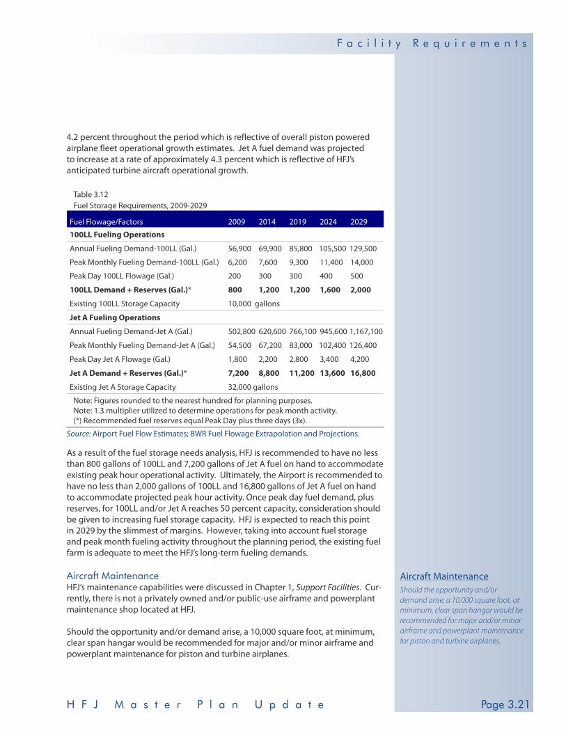
4.2 percent throughout the period which is reflective of overall piston powered airplane fleet operational growth estimates. Jet A fuel demand was projected to increase at a rate of approximately 4.3 percent which is reflective of HFJ’s anticipated turbine aircraft operational growth.
Table 3.12 Fuel Storage Requirements, 2009-2029
Fuel Flowage/Factors 2009 2014 2019 2024 2029
100LL Fueling Operations
Annual Fueling Demand-100LL (Gal.) 56,900 69,900 85,800 105,500 129,500
Peak Monthly Fueling Demand-100LL (Gal.) 6,200 7,600 9,300 11,400 14,000
Peak Day 100LL Flowage (Gal.) 200 300 300 400 500
100LL Demand + Reserves (Gal.)* 800 1,200 1,200 1,600 2,000
Existing 100LL Storage Capacity 10,000 gallons
Jet A Fueling Operations
Annual Fueling Demand-Jet A (Gal.) 502,800 620,600 766,100 945,600 1,167,100
Peak Monthly Fueling Demand-Jet A (Gal.) 54,500 67,200 83,000 102,400 126,400
Peak Day Jet A Flowage (Gal.) 1,800 2,200 2,800 3,400 4,200
Jet A Demand + Reserves (Gal.)* 7,200 8,800 11,200 13,600 16,800
Existing Jet A Storage Capacity 32,000 gallons
Note: Figures rounded to the nearest hundred for planning purposes.Note: 1.3 multiplier utilized to determine operations for peak month activity.(*) Recommended fuel reserves equal Peak Day plus three days (3x).
Source: Airport Fuel Flow Estimates; BWR Fuel Flowage Extrapolation and Projections.
As a result of the fuel storage needs analysis, HFJ is recommended to have no less than 800 gallons of 100LL and 7,200 gallons of Jet A fuel on hand to accommodate existing peak hour operational activity. Ultimately, the Airport is recommended to have no less than 2,000 gallons of 100LL and 16,800 gallons of Jet A fuel on hand to accommodate projected peak hour activity. Once peak day fuel demand, plus reserves, for 100LL and/or Jet A reaches 50 percent capacity, consideration should be given to increasing fuel storage capacity. HFJ is expected to reach this point in 2029 by the slimmest of margins. However, taking into account fuel storage and peak month fueling activity throughout the planning period, the existing fuel farm is adequate to meet the HFJ’s long-term fueling demands.
Aircraft Maintenance HFJ’s maintenance capabilities were discussed in Chapter 1, Support Facilities. Cur-rently, there is not a privately owned and/or public-use airframe and powerplant maintenance shop located at HFJ.
Should the opportunity and/or demand arise, a 10,000 square foot, at minimum, clear span hangar would be recommended for major and/or minor airframe and powerplant maintenance for piston and turbine airplanes.
Aircraft MaintenanceShould the opportunity and/or demand arise, a 10,000 square foot, at minimum, clear span hangar would be recommended for major and/or minor airframe and powerplant maintenance for piston and turbine airplanes.

H F J M a s t e r P l a n U p d a t ePage 2.22
F a c i l i t y R e q u i r e m e n t s
Page 3.22
JKHY performs airframe and powerplant maintenance on its Citation fleet within hangar ‘A’, located north of the airport terminal building, which totals approximately 6,800 square feet hangar floor space This hangar is sufficient to accommodate JKHY’s maintenance needs into the foreseeable future.
Golden Aviation provides airframe and powerplant services to private individuals as well as the company’s own fleet of aircraft within its 30,000 square foot maintenance and manufacturing hangar located south of the main terminal complex. The company is currently expanding this facility by approximately 12,000 square feet to total 42,000 square feet.
Ultimately, in addition to Golden’s existing hangar/maintenance facility, the company plans to build a 120,000 square feet, state-of-the-art, maintenance and assembly building that will be capable of accommodating 36 aircraft undergoing restoration and modernization. The proposed location of this facility is just south of Golden’s existing building.
Snow Removal and Equipment (SRE) Facilities HFJ’s SRE facilities are highlighted in Chapter 1, Support Facilities. FAA AC 150/5220-20, Airport Snow and Ice Control Equipment, and identify the minimum SRE equipment standards for non-commercial service airports experiencing, on average, greater than 10,00 annual operations and receiving approximately 15 inches of snow per year. For HFJ, one high-speed rotary snow plow supported by two displacement plows of equal capacity is recommended for snow removal operations throughout the planning period. Also, HFJ’s existing 4,320 square foot SRE facility is considered adequate to accommodate the SRE pieces throughout the planning period. Based on prevailing weather conditions, operational activ-ity and SRE inventory, HFJ would only require approximately 2,200 square feet of parking and storage area to accommodate current and projected demand.
SUPPORT FACILITY REQUIREMENTS SUMMARY
Table 3.13 summarizes the support facility requirements for HFJ throughout the planning period.
Snow Removal and Equipment FacilitiesOne high-speed rotary snow plow supported by two displacement plows of equal capacity is recommended for snow removal operations throughout the planning period.
UTILITY REQUIREMENTS
HFJ’s utility service and providers were discussed in Chapter 1, Support Facilities. According to airport officials, the existing utilities and utility service providers for HFJ are sufficient to meet existing demand levels. However, it is recommended that these services and providers be reevaluated on a regular basis to ensure the Airport’s utility needs are consistently being met.
OTHER FACILITY REQUIREMENTS
Other facility requirements are those associated with recommended requirements designed to enhance the Airport’s level of environmental compliance and/or improvements dedicated to aviation or non-aeronautical uses, such as future industrial, commercial or potential revenue support areas.
Page 2.23H F J M a s t e r P l a n U p d a t e
F a c i l i t y R e q u i r e m e n t s
Page 3.23
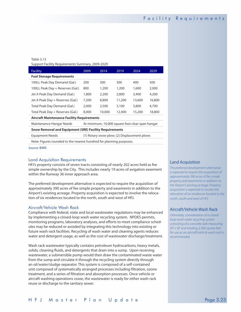
Table 3.13 Support Facility Requirements Summary, 2009-2029
Facility 2009 2014 2019 2024 2029
Fuel Storage Requirements
100LL Peak Day Demand (Gal.) 200 300 300 400 500
100LL Peak Day + Reserves (Gal.) 800 1,200 1,200 1,600 2,000
Jet A Peak Day Demand (Gal.) 1,800 2,200 2,800 3,400 4,200
Jet A Peak Day + Reserves (Gal.) 7,200 8,800 11,200 13,600 16,800
Total Peak Day Demand (Gal.) 2,000 2,500 3,100 3,800 4,700
Total Peak Day + Reserves (Gal.) 8,000 10,000 12,400 15,200 18,800
Aircraft Maintenance Facility Requirements
Maintenance Hangar Needs At minimum, 10,000 square foot clear span hangar
Snow Removal and Equipment (SRE) Facility Requirements
Equipment Needs (1) Rotary snow plow; (2) Displacement plows
Note: Figures rounded to the nearest hundred for planning purposes.
Source: BWR.
Land Acquisition Requirements HFJ’s property consists of seven tracts consisting of nearly 202 acres held as fee simple ownership by the City. This includes nearly 19 acres of avigation easement within the Runway 36 inner approach area.
The preferred development alternative is expected to require the acquisition of approximately 390 acres of fee simple property and easements in addition to the Airport’s existing acreage. Property acquisition is expected to involve the reloca-tion of six residences located to the north, south and west of HFJ.
Aircraft/Vehicle Wash Rack Compliance with federal, state and local wastewater regulations may be enhanced by implementing a closed-loop wash water recycling system. NPDES permits, monitoring programs, laboratory analyses, and efforts to meet compliance sched-ules may be reduced or avoided by integrating this technology into existing or future wash rack facilities. Recycling of wash water and cleaning agents reduces water and detergent usage, as well as the cost of wastewater discharge/treatment.
Wash rack wastewater typically contains petroleum hydrocarbons, heavy metals, solids, cleaning fluids, and detergents that drain into a sump. Upon receiving wastewater, a submersible pump would then draw the contaminated waste water from the sump and circulate it through the recycling system directly through an oil/water/sludge separator. This system is composed of a self-contained unit composed of systematically arranged processes including filtration, ozone treatment, and a series of filtration and absorption processes. Once vehicle or aircraft washing operations cease, the wastewater is ready for either wash rack reuse or discharge to the sanitary sewer.
Aircraft/Vehicle Wash RackUltimately, consideration of a closed-loop wash water recycling system consisting of a concrete slab measuring 50’ x 50’ and totaling 2,500 square feet for use as an aircraft/vehicle wash rack is recommended.
Land AcquisitionThe preferred development alternative is expected to require the acquisition of approximately 390 acres of fee simple property and easements in addition to the Airport’s existing acreage. Property acquisition is expected to involve the relocation of six residences located to the north, south and west of HFJ.

H F J M a s t e r P l a n U p d a t ePage 2.24
F a c i l i t y R e q u i r e m e n t s
Page 3.24
Ultimately, consideration of a closed-loop wash water recycling system consisting of a concrete slab measuring 50’ x 50’ and totaling 2,500 square feet for use as an aircraft/vehicle wash rack is recommended. Ideally, this wash rack system will be located within the main terminal complex and immediately adjacent to the aircraft parking apron.
Fuel Truck Parking Area/Spill Containment Berm As part of any future HFJ Spill Prevention Control and Countermeasure Plan (SPCC), a fuel spill containment berm is recommended to be developed around an existing and/or future fuel truck parking area to protect local groundwater sources from potential contamination arising from a fuel spill or leakage. Currently, JKHY employs the use of a 2,000 gallon capacity fuel truck to dispense fuel to the com-pany’s fleet of aircraft. The City-operated FBO dispenses fuel via a 24-hour card reader, fuel pump and meter.
A concrete/gravel fuel truck parking area measuring 30’ x 46’ totaling approximately 1,400 square feet is recommended to accommodate current fuel truck operations taking place at HFJ. Additionally, construction of an earthen berm around the perimeter of the parking area for fuel truck storage is recommended. Lastly, the fuel truck parking area is recommended to be located immediately adjacent to the parking apron. This berm would be approximately eight inches in height with a bentonite clay core. The berm would be also constructed on the down gradient side of the aircraft apron in order to ensure that any fuel spills would be directed to the berm and prevent petroleum products from contaminating groundwater or soils in the area.
TRIGGER POINTS FOR FACILITY EXPANSION
The timing and need for particular capital improvements recommended for HFJ is dependent on projections of future aviation demand or ‘trigger points,’ rather than years. Table 3.14 summarizes the trigger points that will most likely dictate initiation of capital improvements at the Airport throughout the planning period. As the overall operational environment of the Airport fluctuates, such as demand activity, the triggers which encourage development at the Airport might also change. Therefore, it is crucial that the airport sponsor monitor actual conditions and demand activity levels at the Airport on a regular basis. The facility requirement analysis for HFJ is recommended to be periodically revisited to confirm trigger points and operational demand in an attempt to accurately gauge the appropriate timing of facility needs. Capital improvement and facility expansion is recommended only when actual demand justifies and as long as the improvements are environmentally sound, as well as operationally and financially feasible.
The trigger points contained within Table 3.14 are suggested to be coordinated with Table 3.5, Airfield/Airspace Facility Requirements Summary, 2009-2029, Table 3.11, Terminal Area Facility Requirements Summary, 2009-2029 and Table 3.13, Support Facility Requirements Summary, 2009-2029 when determining appropriate timing and development of recommended airfield and terminal area facilities at HFJ.
Fuel Truck Parking AreaA concrete/gravel fuel truck parking area measuring 30’ x 46’ totaling approximately 1,400 square feet is recommended to accommodate current fuel truck operations taking place at HFJ. Additionally, construction of an earthen berm around the perimeter of the parking area for fuel truck storage is recommended. Lastly, the fuel truck parking area is recommended to be located immediately adjacent to the parking apron.

Page 2.25H F J M a s t e r P l a n U p d a t e
F a c i l i t y R e q u i r e m e n t s
Page 3.25
Table 3.14 Facility Development Trigger Point Summary, 2009-2029
Facility Type TriggerTrigger Point (As Demand Warrants)
Airfield/Airspace Facilities
Rwy 18-36 Dimensional Criteria 500 C-II Operations/ Based Aircraft Phase II (2014-2018)
Rwy 18-36 Extension to 5,900 (C-II)
500 C-II Operations/ Based Aircraft Phase II (2014-2018)
Pavement Strength Upgrade* ARC C-II Designation Phase II (2014-2018)
Taxiway Upgrades Runway Extension/Widening Phase II (2014-2018)
Marking Requirements (18-36) ARC C-II Designation Phase II (2014-2018)
Lighting Upgrades** 50:1 PI Approach (as low as ½-mile) Phase II (2014-2018)
AWOS Relocation/Upgrades Existing Activity Phase I (2009-2013)
50:1 PI Approach (Rwy 36) Runway Extension to 5,900’ Phase II (2009-2013)
Establish New IAP (Rwy18) Existing Activity Phase I (2009-2013)
Terminal Area Facilities
Terminal Building Improvements 26 Peak Hour Passengers Phase III (2019-2029)
T-Hangar Development Existing Activity Phase I/II/III (2009-2029)
Clear Span Hangar Development Existing Activity Phase I/II/III (2009-2029)
Apron Area/Tie-Down Expansion 32 Peak Day Arrivals Phase II (2014-2018)
Support Facilities
Maint. Hangar Development Existing Activity Phase III (2019-2029)
Other Facility Requirements
Land Acquisition Existing Activity (TBD) Phase I (2009-2013)
Aircraft/Vehicle Wash Rack Existing Activity Phase I (2009-2013)
Fuel Truck Parking Area Existing Activity Phase I (2009-2013)
(*) Includes runway, taxiway system and apron areas.(**) Includes the approach lighting system and runway lighting. AWOS- Automated Weather Observing SystemPI- Precision instrumentIAP- Instrument Approach Procedure
Source: BWR; HFJ Facility Requirements.
