chapter two: introduction to material properties of...
TRANSCRIPT
Chapter Two: Introduction to material properties of steel
STRUCTURAL STEEL PROPERTIES
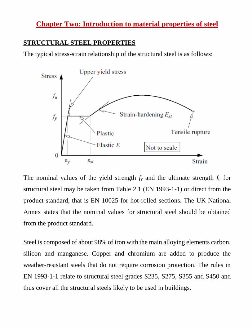
The typical stress-strain relationship of the structural steel is as follows:
The nominal values of the yield strength fy and the ultimate strength fu for
structural steel may be taken from Table 2.1 (EN 1993-1-1) or direct from the
product standard, that is EN 10025 for hot-rolled sections. The UK National
Annex states that the nominal values for structural steel should be obtained
from the product standard.
Steel is composed of about 98% of iron with the main alloying elements carbon,
silicon and manganese. Copper and chromium are added to produce the
weather-resistant steels that do not require corrosion protection. The rules in
EN 1993-1-1 relate to structural steel grades S235, S275, S355 and S450 and
thus cover all the structural steels likely to be used in buildings.
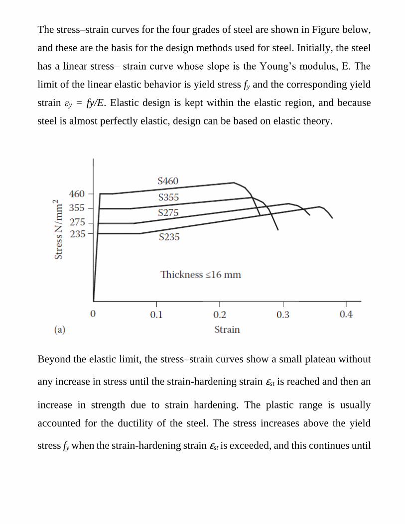
The stress–strain curves for the four grades of steel are shown in Figure below,
and these are the basis for the design methods used for steel. Initially, the steel
has a linear stress– strain curve whose slope is the Young’s modulus, E. The
limit of the linear elastic behavior is yield stress fy and the corresponding yield
strain εy = fy/E. Elastic design is kept within the elastic region, and because
steel is almost perfectly elastic, design can be based on elastic theory.
Beyond the elastic limit, the stress–strain curves show a small plateau without
any increase in stress until the strain-hardening strain εst is reached and then an
increase in strength due to strain hardening. The plastic range is usually
accounted for the ductility of the steel. The stress increases above the yield
stress fy when the strain-hardening strain εst is exceeded, and this continues until

the ultimate tensile stress fu is reached. Plastic design is based on the horizontal
part of the stress–strain shown in Figure below.
Structural Steel Properties
Fatigue
Fatigue failure can occur in members or structures subjected to fluctuating loads
such as crane girders, bridges and structures that support machinery, wind and
wave loading. Failure occurs through initiation and propagation of a crack that
starts at a fault or structural discontinuity, and the failure load may be well
below its static value. Welded connections have the greatest effect on the
fatigue strength of steel structures. Tests show that butt welds give the best
performance in service, whilst continuous fillet welds are much superior to
intermittent fillet welds. Bolted connections do not reduce the strength under
fatigue loading. To help avoid fatigue failure, detail should be such that stress
concentrations and abrupt changes of section are avoided in regions of tensile
stress.
Ductility requirements
Ductility is the ability of a material to undergo large deformation without
breaking. A measure of ductility is the percentage elongation of the gage length
of the specimen during a tension test. It is calculated as 100 times the change
in gage length divided by the original gage length. Thus,
e Lf L0 100 L0
where
Lf is the final distance between the gage marks after the specimen breaks
L0 is the original gage length
In order to ensure structures are designed with steels that possess adequate
ductility, NA to BS EN 1993-1-1 sets the following requirements:
1- Elastic global analysis
The limiting values for the ratio fu/fy, the elongation at failure and the ultimate
strain εu for elastic global analysis are given as follows:
a- fu/fy ≥ 1.10.
b- Elongation at failure not less than 15%.
c- εu ≥ 15 εy, where εu is the ultimate strain and εy is the yield strain.
2- Plastic global analysis
Plastic global analysis should not be used for bridges. For building the limiting
values for the ratio fu/fy, the elongation at failure and the ultimate strain εu for
plastic global analysis are given as follows:
a- fu/fy ≥ 1.15
b- Elongation at failure not less than 15%.
c- εu ≥ 20 εy, where εu is the ultimate strain and εy is the yield strain
Brittle fracture
Structural steel is ductile at temperatures above 10°C, but it becomes more
brittle as the temperature falls, and fracture can occur at low stresses below 0°
C. The material should have sufficient fracture toughness to avoid brittle
fracture of tension member at the lowest service temperature expected to occur
within the intended design life of the structure. NA to BS EN 1993-1 sets the
following requirements:
For building and other quasi-statically loaded structures, the lowest
service temperature in the steel should be taken as the lowest air
temperature that may be taken as −5°C for internal steelwork and −15°C
for external steelwork.
For bridges, the lowest service temperature in the steel should be
determined according to the NA to BS EN 1991-1-5 for bridge location.
For structures susceptible to fatigue, it is recommended that the
requirements for bridges should be applied.
In other cases, the lowest service temperature in the steel should be taken
as the lowest air temperature expected to occur within the intended design
life of the structure.
Brittle fracture is initiated by the existence or formation of a small crack in a
region of high local stress. Once initiated, the crack may propagate in a ductile
fashion for which the external forces must supply the energy required to tear
the steel. The ductility of a structural steel depends on its composition, heat
treatment and thickness and varies with temperature. The Figure below shows
the increase with temperature of the capacity of the steel to absorb energy
during impact. At low temperatures, the energy absorption is low, and initiation
and propagation of brittle fractures are comparatively easy, whilst at high
temperatures, the energy absorption is high because of ductile yielding, and the
propagation of the cracks can be arrested.
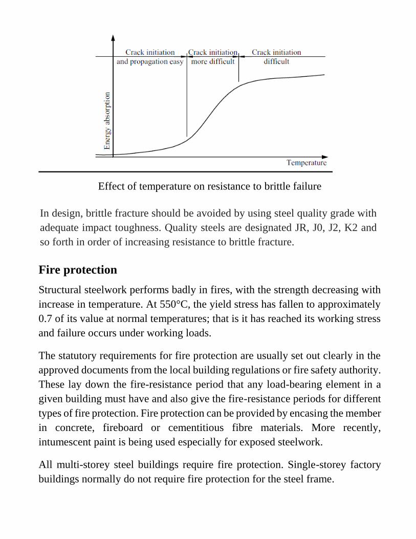
Effect of temperature on resistance to brittle failure
In design, brittle fracture should be avoided by using steel quality grade with
adequate impact toughness. Quality steels are designated JR, J0, J2, K2 and
so forth in order of increasing resistance to brittle fracture.
Fire protection
Structural steelwork performs badly in fires, with the strength decreasing with
increase in temperature. At 550°C, the yield stress has fallen to approximately
0.7 of its value at normal temperatures; that is it has reached its working stress
and failure occurs under working loads.
The statutory requirements for fire protection are usually set out clearly in the
approved documents from the local building regulations or fire safety authority.
These lay down the fire-resistance period that any load-bearing element in a
given building must have and also give the fire-resistance periods for different
types of fire protection. Fire protection can be provided by encasing the member
in concrete, fireboard or cementitious fibre materials. More recently,
intumescent paint is being used especially for exposed steelwork.
All multi-storey steel buildings require fire protection. Single-storey factory
buildings normally do not require fire protection for the steel frame.
Corrosion protection
Exposed steelwork can be severely affected by corrosion in the atmosphere,
particularly if pollutants are present, and it is necessary to provide surface
protection in all cases. The type of protection depends on the surface conditions
and length of life required.
The main types of protective coatings are
1- Metallic coatings: A sprayed-on in-line coating of either aluminium or
zinc is used, or the member is coated by hot dipping it in a bath of molten
zinc in the galvanizing process.
2- Painting, where various systems are used: One common system consists
of using a primer of zinc chromate followed by finishing coats of
micaceous iron oxide. Plastic and bituminous paints are used in special
cases.
The single most important factor in achieving a sound corrosion-protection
coating is surface preparation. Steel is covered with mill scale when it cools
after rolling, and this must be removed before the protection is applied;
otherwise, the scale can subsequently loosen and break the film. Blast cleaning
makes the best preparation prior to painting.
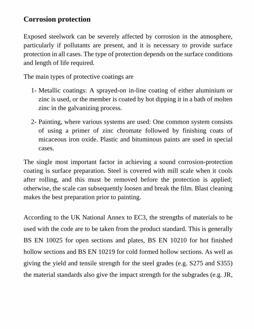
According to the UK National Annex to EC3, the strengths of materials to be
used with the code are to be taken from the product standard. This is generally
BS EN 10025 for open sections and plates, BS EN 10210 for hot finished
hollow sections and BS EN 10219 for cold formed hollow sections. As well as
giving the yield and tensile strength for the steel grades (e.g. S275 and S355)
the material standards also give the impact strength for the subgrades (e.g. JR,
J0 and J2). The strengths for various thicknesses are given in the following
Table.
STEEL SECTIONS
1- Rolled and formed sections
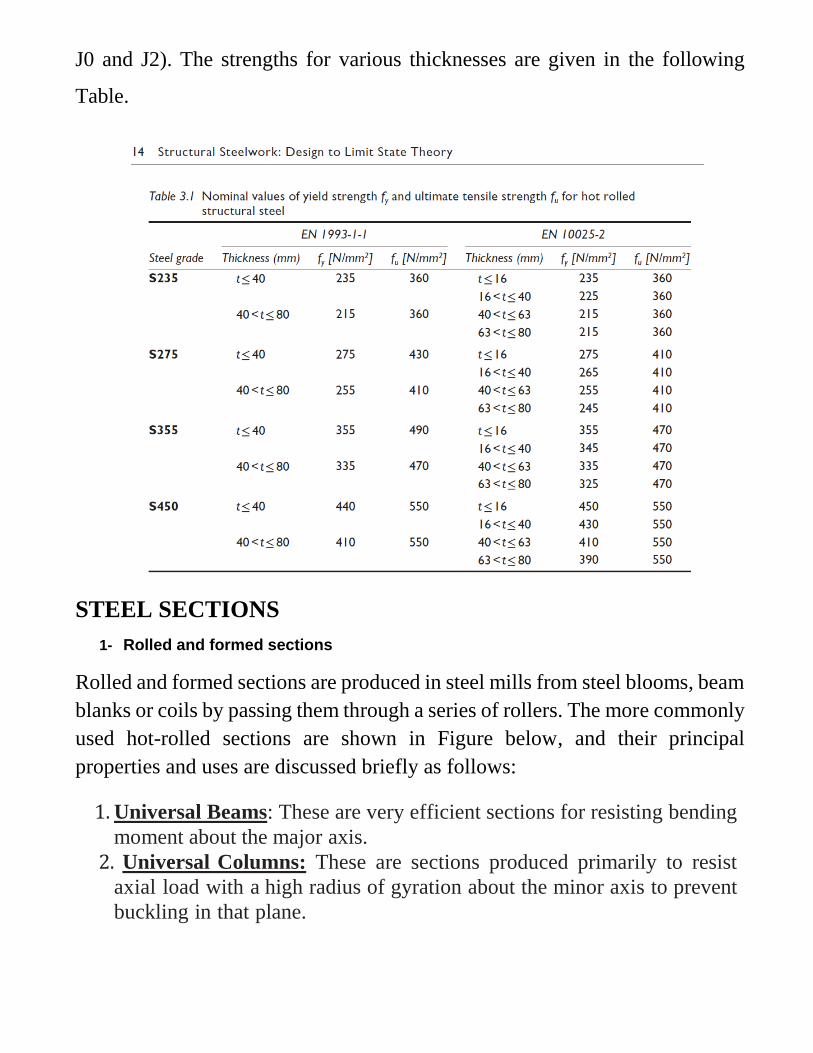
Rolled and formed sections are produced in steel mills from steel blooms, beam
blanks or coils by passing them through a series of rollers. The more commonly
used hot-rolled sections are shown in Figure below, and their principal
properties and uses are discussed briefly as follows:
1. Universal Beams: These are very efficient sections for resisting bending
moment about the major axis.
2. Universal Columns: These are sections produced primarily to resist
axial load with a high radius of gyration about the minor axis to prevent
buckling in that plane.

3. Channels: These are used for beams, bracing members, truss members
and compound members.
4. Equal and unequal angles: These are used for bracing members, truss
members and for purlins, side and sheeting rails.
5. Structural tees: The sections shown are produced by cutting a universal
beam or column into two parts. Tees are used for truss members, ties and
light beams.
6. Circular, square and rectangular hollow sections: These are mostly
produced from hot-rolled coils and may be hot finished or cold formed.
A welded mother tube is first formed, and then it is rolled to its final
square or rectangular shape. In the hot process, the final shaping is
done at the steel normalizing temperature, whereas in the cold process,
it is done at ambient room temperature. These sections make very
efficient compression members and are used in a wide range of
applications as members in roof trusses, lattice girders, building frames
and for purlins, sheeting rails, etc.
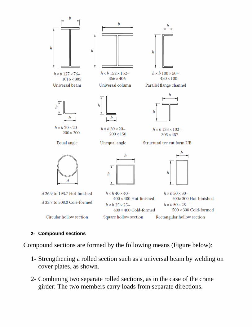
2- Compound sections
Compound sections are formed by the following means (Figure below):
1- Strengthening a rolled section such as a universal beam by welding on
cover plates, as shown.
2- Combining two separate rolled sections, as in the case of the crane
girder: The two members carry loads from separate directions.

3- Connecting two members together to form a strong combined member:
Examples are the laced and battened members.
3- Built-up sections
Built-up sections are made by welding plates together to form I, H or box
members that are termed plate girders, built-up columns, box girders or
columns, respectively. These members are used where heavy loads have to be
carried and in the case of plate and box girders where long spans may be
required. Examples of built-up sections are shown.

4- Cold-rolled open sections
Thin steel plates can be formed into a wide range of sections by cold rolling.
The most important uses for cold-rolled open sections in steel structures are
for purlins, side and sheeting rails. Three common sections – the zed, sigma
and lipped channel are shown.
SECTION PROPERTIES
For a given member serial size, the section properties are
1. The exact section dimensions
The dimensions of sections are given in millimetres (mm). Generally, the
centimeter (cm) is used for the calculated properties, but for surface areas and
for the warping constant (Iw), the meter (m) and the decimeter (dm),
respectively, are used.
2. The location of the centroid if the section is asymmetrical about one or
both axes.
The axis system used in EN 1993 is
x along the member
y major axis, or axis perpendicular to web
z minor axis, or axis parallel to web
3. Area of cross section (A)
4. Second moments of area about various axes

The second moment of area has been calculated taking into account all tapers,
radii and fillets of the sections. Values are given about both the y–y and the z–
z axes, named Iy and Iz, respectively.
5. Radii of gyration about various axes
The radius of gyration is a parameter used in the calculation of buckling
resistance and is derived as follows:
6. Moduli of section for various axes, both elastic and plastic
The elastic section modulus is used to calculate the elastic design resistance
for bending based on the yield strength of the section and the partial factor 𝛾𝑀
or to calculate the stress at the extreme fiber of the section due to a moment. It
is derived as follows:
where z, y are the distance to the extreme fibers of the section from the elastic
y–y and z–z axes, respectively.
The plastic section modulus about both y–y and z–z axes of the plastic cross
sections is tabulated for all sections except angle sections.
For compound and built-up sections, the properties must be calculated from
the first principles. The section properties for the symmetrical I section with
dimensions as shown in Figure below are as follows:
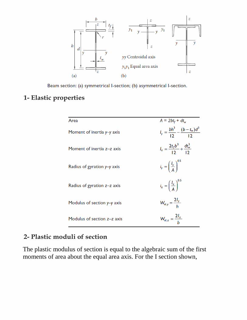
1- Elastic properties
2- Plastic moduli of section
The plastic modulus of section is equal to the algebraic sum of the first
moments of area about the equal area axis. For the I section shown,
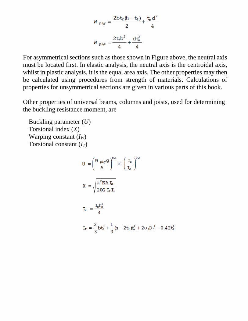
For asymmetrical sections such as those shown in Figure above, the neutral axis
must be located first. In elastic analysis, the neutral axis is the centroidal axis,
whilst in plastic analysis, it is the equal area axis. The other properties may then
be calculated using procedures from strength of materials. Calculations of
properties for unsymmetrical sections are given in various parts of this book.
Other properties of universal beams, columns and joists, used for determining
the buckling resistance moment, are
Buckling parameter (U)
Torsional index (X)
Warping constant (IW)
Torsional constant (IT)
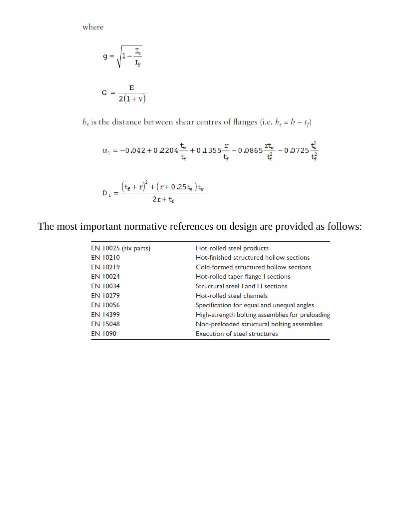
The most important normative references on design are provided as follows: