chapter10 refrigeration cycle 10-1 vapor-compression cycle 10-1-1 the reversed carnot cycle t s 4 1...
TRANSCRIPT


Chapter10 Refrigeration Cycle

10-1 Vapor-Compression Cycle
10-1-1 The Reversed Carnot Cycle10-1-1 The Reversed Carnot Cycle
w
qCOP L
c
14
14
ssTT
ssT
LH
L
LH
L
TT
T
T
s
4 1
23TH
TL
1
1
L
H
TT
Coefficient of Performance

Disadvantages
•Process 2-3 is difficult to be Fulfill in compressor
•Process 4-1 will do harm to turbine

10-1-2 The Ideal Vapor-Compression Refrigeration Cycl10-1-2 The Ideal Vapor-Compression Refrigeration Cyclee
condenser
Equipments:
1
2
3
4
compressor
Expansion valve
evaporator

T
s
TH
TL1
2
3
4

condenser
compressor
evaporator
Capillary tube
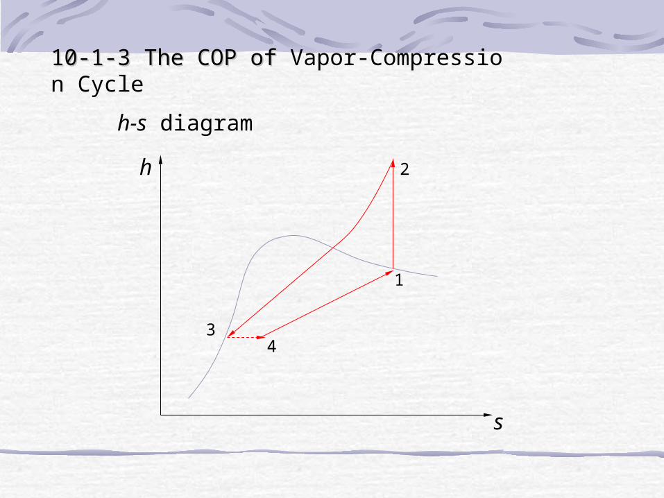
10-1-3 The COP of 10-1-3 The COP of Vapor-Compression Cycleh-s diagram
h
s
1
2
34

Usually p1, p2 are available
h
s
1
2
34
From p1, get h1”, s1”
h1 = h1” s1 = s1”
From p2 , s1, get h2
From p2 , get h2’
h3= h2’
h4 = h3
w
qCOP L
12
41
hh
hh

p-h diagram

p
h
1
23
4

10-2 Refrigerant
•Ammonia
•CFC(chlorofluorocarbons)
•water
Good refrigerant
High enthalpy of vaporization
Not too low evaporator pressure
Not too high condenser pressure
Nontoxic
Noncorrosive
Chemically stable
Low cost

10-3 Heat PumpAn equipment Absorbing heat from environment for heating purpose
T
s
TH
T01
2
3
4
12
32
hh
hhCOPhp
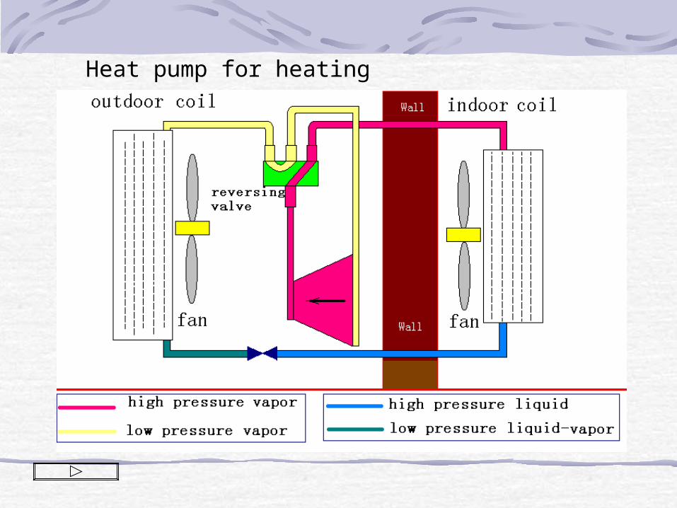
Heat pump for heating

Heat pump for refrigeration

10-4 Innovative Vapor-compression Refrigeration Systems
10-4-1 Regenerative Vapor Compression cycleEquipmentsEquipments
condenser
evaporator
Heat exchange
r
separator
compressor

T
s
TH
TL1
2
3
4
T-s DiagramT-s Diagram
2’
1’
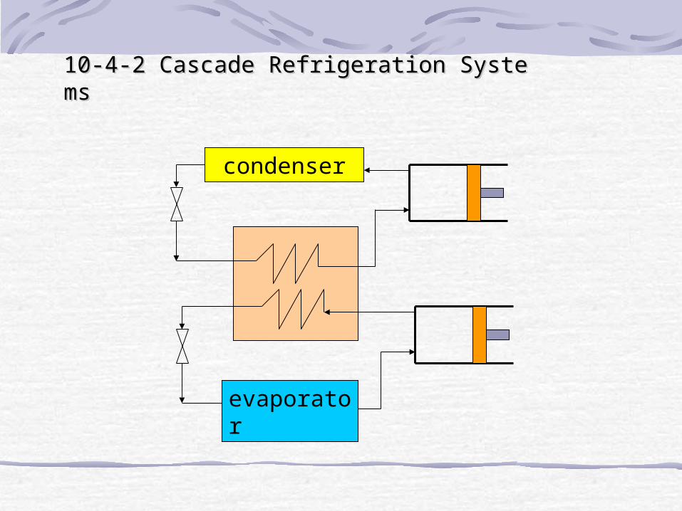
10-4-2 Cascade Refrigeration Systems10-4-2 Cascade Refrigeration Systems
condenser
evaporator

T
s
T0
T-s DiagramT-s Diagram

10-4-3 Multistage Compression Refrigeration Syste10-4-3 Multistage Compression Refrigeration Systemsms
condenser
evaporator
Flash chamber
1
2
3
heat exchanger
45
6
7
8
9
T
s
1
2
3
4
5
67
8
9

10-4-4 Multipurpose Refrigeration Systems with a Single C10-4-4 Multipurpose Refrigeration Systems with a Single Compressorompressor
condenser
Freezer
refrigerator
1
2
3
4
5
6
Alternative path
T
s
1
2
3
4
5

10-4-5 Liquefaction of Gas10-4-5 Liquefaction of Gas
Heat exchanger
Make up gas
Liquid removed
Multistage compressor
1
2
3
4
5

T
s
1
2
1
3
45

10-5 Gas Refrigeration cycle
10-4-1 Equipments
Heat exchanger
QH
Heat exchanger
QL
compressor
turbine

T
s
p2
p1
1
2
3
4
T0
TL

10-4-2 COP of Gas Refrigeration Cycle
4132
41
hhhh
hhCOP
4132
41
TTTTC
TTC
p
p
1
1
41
32
TT
TT
T
s
1
2
3
4
T0
TL

k
k
T
T
T
T 1
4
3
1
2
1
2
41
32
T
T
TT
TT
1
1
1
2
TT
COP
T
s
1
2
3
4
T0
TL
1
11
k
k

Since
1
11
k
kCOP
•To decrease compression ratio can increase COP
•To To decrease compression ratio will decrease power ratio

T
s
T0
TL
T
s
T0
TL
1
2
4
5
3
q
6
q
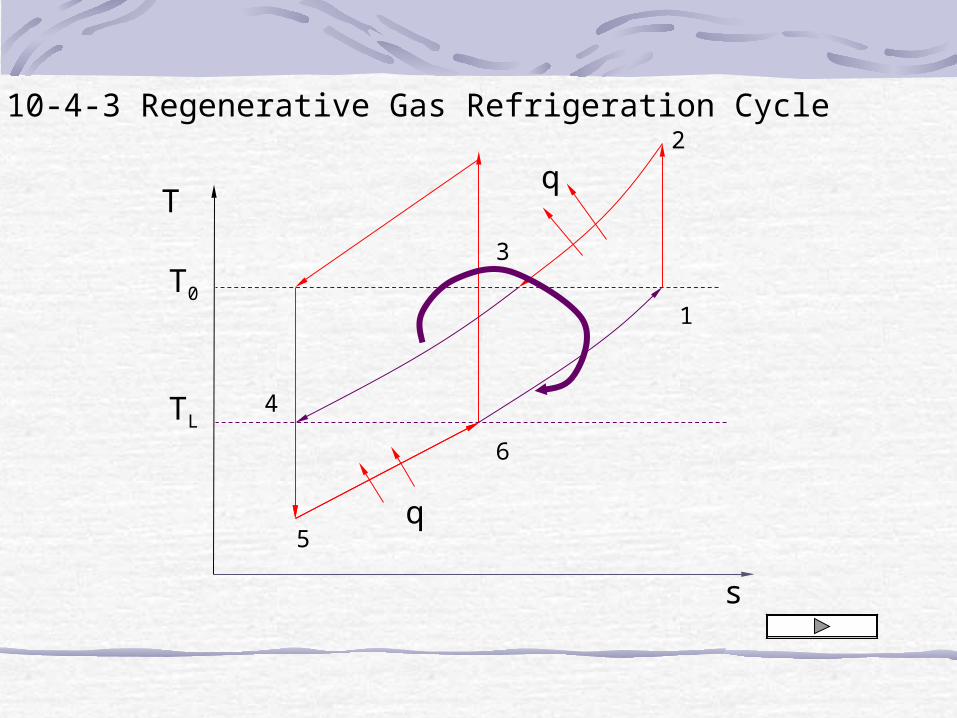
10-4-3 Regenerative Gas Refrigeration Cycle

Heat exchanger
QH
Heat exchanger
QL
compressor
turbine
regenerator
1 2
34 5
6

10-6 Absorption Refrigeration System
heat
condenser
evaporator
=compressor

Refrigerant: Ammonia
Transport medium: Water
Refrigerant: Water
Transport medium: Lithium bromide

10-6 Adsorption Refrigeration
Solar energy
Active carbon
evaporator
condenser
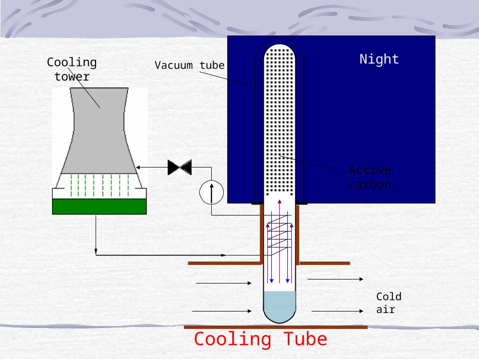
Cooling Tube
Solar energyNight
Cold air
Active carbon
Vacuum tubeCooling tower

The End of This Chapter
Thank You